Article

A Fast Multi-Switched Inductor Balancing System Based on a Fuzzy Logic Controller for Lithium-Ion Battery Packs in Electric Vehicles

1
Faculty of Science, Engineering and Technology, Swinburne University of Technology, Hawthorn, VIC 3122, Australia
2
School of Electrical Engineering and Automation, Anhui University, Hefei 230000, China
*
Author to whom correspondence should be addressed.
Energies 2017, 10(7), 1034; https://doi.org/10.3390/en10071034
Submission received: 7 June 2017 / Revised: 6 July 2017 / Accepted: 14 July 2017 / Published: 19 July 2017
(This article belongs to the Section D: Energy Storage and Application)

Abstract

:
Based on a low cost multi-switched inductor balancing circuit (MSIBC), a fuzzy logic (FL) controller is proposed to improve the balancing performances of lithium-ion battery packs instead of an existing proportional-integral (PI) controller. In the proposed FL controller, a cell’s open circuit voltages (OCVs) and their differences in the pack are used as the inputs, and the output of the FL controller is the balancing current. The FL controller for the MSIBC has the advantage of maintaining high balancing currents over the existing PI controller in almost the entire balancing process for different lithium battery types. As a result, the proposed FL controller takes a much shorter time to achieve battery pack balancing, and thus more pack capacity can be recovered. This will help to improve the pack performance in electric vehicles and extend the serving time of the battery pack.

1. Introduction

The wide usage of gasoline vehicles leads to the massive emission of greenhouse gases such as carbon dioxide. Electric vehicles (EVs) are promising to reduce this emission. In EVs, lithium based batteries have become the dominant energy source due to their high-energy density, long cycle life, and low self-discharge rate [1,2]. The voltage of a single cell is typically less than 4.2 V. They are usually connected in series to achieve high voltage output (around 300 V) and meet the power requirements of EVs. Such series connection may lead to a voltage or state of charge (SOC) imbalance over long periods of charging and discharging operation since the cells in the pack have different self-discharge rates and charging and discharging efficiencies. In such an imbalanced battery pack, the weakest cell determines the pack capacity. A balancing system is required to improve the pack capacity.
Battery balancing systems are generally categorized into two groups; passive and active [3]. Passive balancing systems turn extra energy from the cells with higher voltage or SOC into heat through shunt resistance at a low implementation cost. Owing to thermal concerns, the balancing current has to be small, resulting in low balancing speed. Active balancing systems transfer charge or energy within a pack through balancing circuits to maximize the pack capacity. These active balancing systems can potentially have high balancing currents and high balancing speeds.
In active balancing systems, the balancing circuits (BCs) can be divided into three groups on the basis of the main component that transfers charge or energy among the cells in a pack; capacitor-based balancing circuits (CBCs) [4,5,6,7,8], transformer-based balancing circuits (TBCs) [9,10,11,12,13,14,15,16,17], and inductor-based balancing circuits (IBCs) [18,19,20,21,22,23,24,25,26,27,28,29,30,31]. CBCs generally have low implementation costs, but their balancing speed is slow, especially when the voltage differences among the cells in the pack are low. TBCs typically have high balancing speeds, but their cost is high due to the use of a transformer. IBCs have overall better performance with a trade-off between balancing speed and cost [32].
In IBCs, two families of BCs are widely used [32]; Cuk converter-based BCs (CukBCs) [18,19,20,21,22,23] and buck-boost converter-based BCs (Buck-BoostBCs) [24,25,26,27,28]. Generally, there are more components in the CukBCs than the Buck-BoostBCs. Among the Buck-BoostBCs, the multi-switched inductor BC (MSIBC) is the simplest to date, requiring only one MOSFET and one inductor for each cell [24]. This paper focuses on the cost, the speed, and the final recovered pack capacity. From the cost aspect, the MSIBC was chosen. A FL controller designed for the MSIBC in this study has the merits of a faster balancing speed and the ability to recover more pack capacity compared to the PI controller in the literature [25]. In the PI controller based balancing system, the balancing current is adjusted to the highest amplitude because of the largest voltage difference of the cells, which occurs at the beginning of the balancing process. The balancing current declines quickly when the voltage differences between the cells become smaller in the process of balancing. The PI controller with constant gain cannot adjust its balancing current adaptively, which severely affects its balancing performance.
In this paper, a FL controller is proposed to control a MSIBC balancing system instead of the existing PI controller. The FL controller significantly improves the balancing speed and increases the pack capacity. As a result, the FL controller for the low cost MSIBC balancing system can obtain more pack capacity and thus extend the serving time of the battery pack in an EV. The FL controller was applied to the CukBC [18,20,22,23] and the Buck-BoostBCs [33] that have more components and higher implementation costs. In the MSIBC, a proposed FL controller was designed based on the characteristics of this balancing circuit and the batteries. The FL controller changes the off-state durations of MOSFETs to adjust the amplitudes and directions of balancing currents and can maintain high balancing currents during most of the balancing process and achieve a high balancing speed.
The following parts of this paper are arranged as follows. In Section 2, the MSIBC and the operational principle of the MSIBC, with the open circuit voltage (OCV) as a balancing criterion, are explained. The design of the FL controller is explained in Section 3. Section 4 describes the experimental results with the FL and PI controllers. These are discussed in Section 5. The conclusions and suggestions for future work are provided in Section 6.

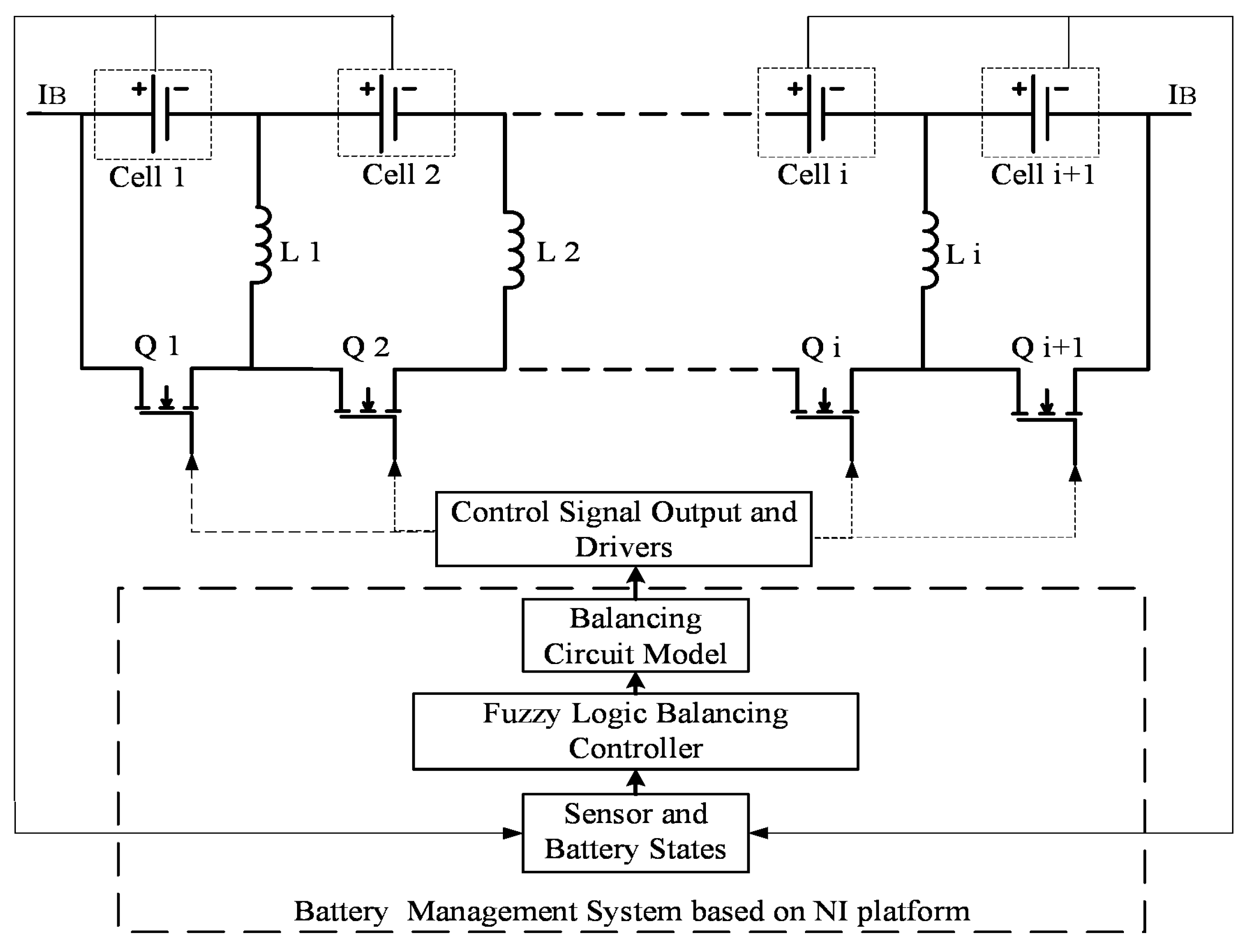
2. Results Multi-Switched Inductor Balancing System

2.1. Multi-Switched Indictor Balancing Circuit

Figure 1 shows a MSIBC-based balancing system [25]. It mainly consists of a MSIBC and a FL controller. The MISBC is operated in different modes. In each mode, one cell is disconnected from the BC. The mode duration, namely, the MOSFET off-state duration, affects the direction and amplitude of the balancing currents. The FL controller is implemented in the National Instruments (NI) data acquisition platform and the FPGA module. The membership functions of the FL controller are designed based on the characteristics of both the balancing circuit and the battery cell.
In the following, a four-cell battery pack is taken as an example to explain the MSIBC, which is comprised of three inductors and four power MOSFETs. There are four control signals for the MOSFETs, as shown in Figure 2, resulting in four working modes, as shown in Figure 3. A short dead-time (DT) is inserted in each mode to avoid short circuits.
Assuming that the MSIBC operates in the steady state, according to Kirchhoff’s current law, the relationship between the cell balancing current and the mode duration can be expressed as:
( I b 1 I b 2 I b 3 I b 4 ) = [ ( d 2 + d 3 + d 4 ) ( d 3 + d 4 ) d 4 d 1 ( d 3 + d 4 ) d 4 d 1 d 1 + d 2 d 4 d 1 d 1 + d 2 d 1 + d 2 + d 3 ]     ( I L 1 I L 2 I L 3 )     ( 1 T )
where d x represents the mode duration as percentage of one period for mode x (x = 1, 2, 3, 4) and T is the switching period. It can be seen from Equation (1) that the cell balancing current is decided by both the inductor current and the mode duration.
According to the volt-second balance, the relationship between the cell voltage and the mode duration can be expressed as [34]:
{ ( V b 2 + V b 3 + V b 4 )     d 1     T + ( V b 1 )     ( d 2 + d 3 + d 4 )     T = 0 ( V b 3 + V b 4 )     ( d 1 + d 2 )     T + ( V b 1 V b 2 )     ( d 3 + d 4 )     T = 0 V b 4     ( d 1 + d 2 + d 3 )     T + ( V b 1 V b 2 V b 3 )     d 4     T = 0
In relation to the inductor resistance ( R L ) and the MOSFET conduction resistance ( R o n ) in the MSIBC, the relationship between the inductor balancing current and the MOSFET mode duration is given by [24]:
( V b 1 R o n + I L 1 + I L 2 + I L 3 + I L 1 R L R o n V b 1 + V b 2 R o n + I L 1 + 2 I L 2 + 2 I L 3 + I L 2 R L R o n V b 1 + V b 2 + V b 3 R o n + I L 1 + 2 I L 2 + 3 I L 3 + I L 3 R L R o n ) = ( V p R o n 2 I L 1 I L 2 I L 2 + I L 3 I L 3 V p R o n I L 1 + I L 3 V p R o n + I L 1 + I L 3 2 I L 3 V p R o n + I L 2 + 2 I L 3 V p R o n + I L 1 + I L 2 + 2 I L 3 V p R o n + I L 1 + 2 I L 2 + 2 I L 3 )   ( d 1 d 2 d 3 )
where, V p is the pack voltage.

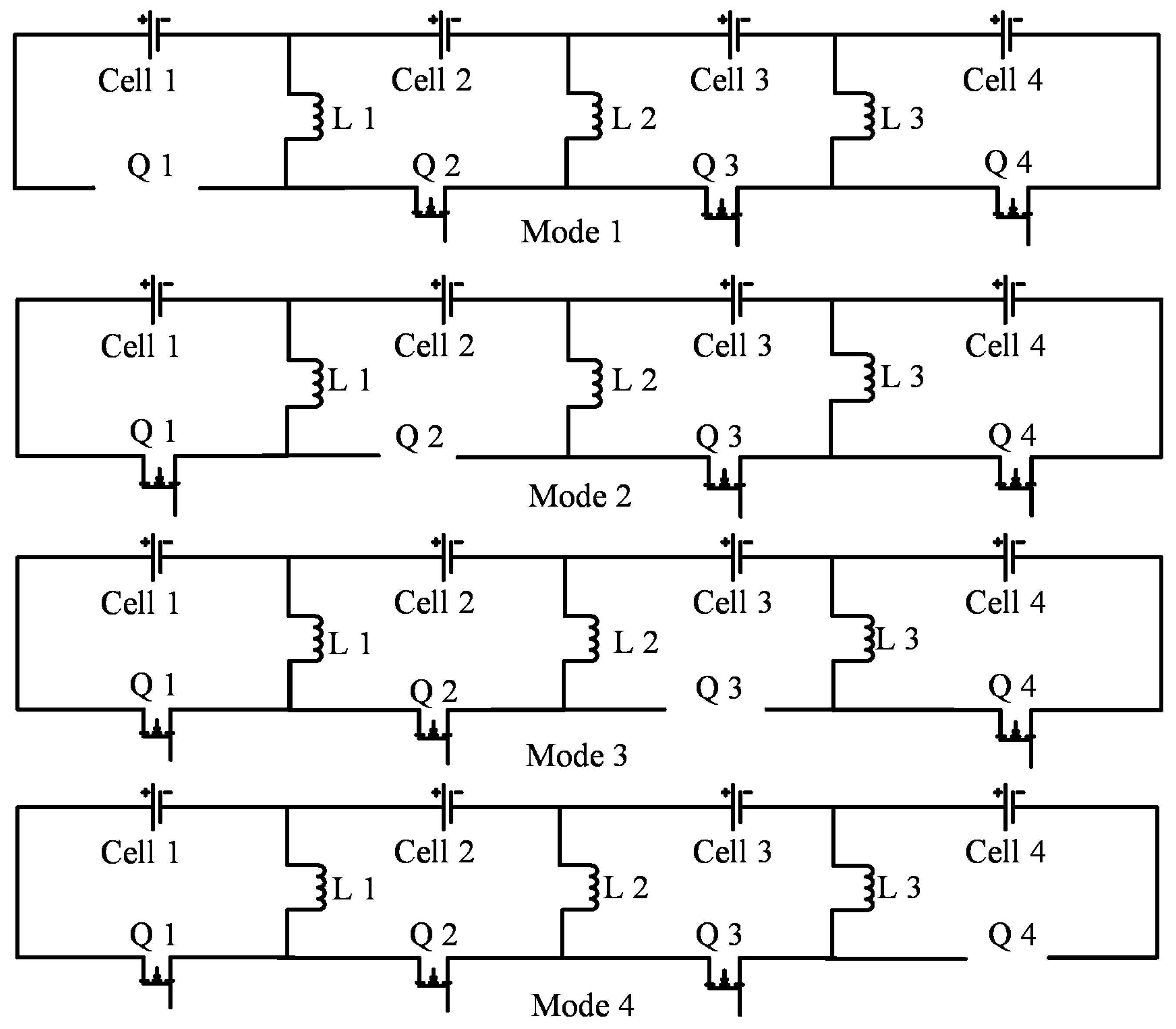
2.2. Balancing Principle
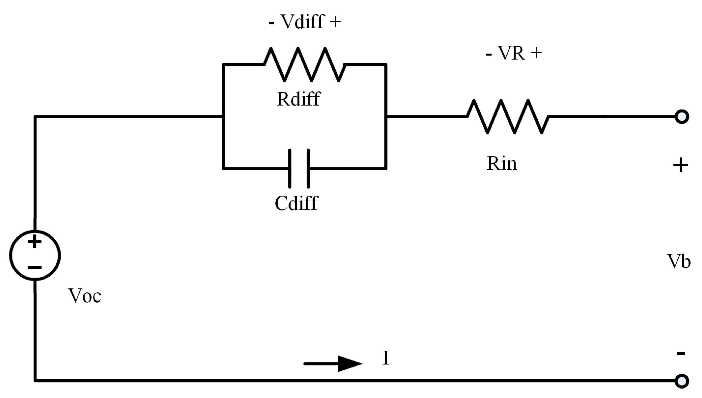
The MSIBC uses an inductor to transfer energy in a cell by switching MOSFETs in sequence. The direction of energy transfer is decided by both the cell voltage and the mode duration. By changing the ratio of mode-duration to cell-voltage (RMV), the cell balancing current direction can be controlled. If the RMVs of all the cells are the same, the average cell balancing current is zero. The voltages of all the cells remain the same; thus no balancing action on the cells takes place. If the RMV of one cell is higher than that of the others, this cell is charged. If the RMV of one cell is lower than that of others in the pack, this cell is discharged. If cell one in the pack is taken as an example, it can be mathematically expressed as:
{ d 1 V b 1 = d 2 V b 2 = d 3 V b 3 = d 4 V b 4        No   Cell   is   balanced d 1 V b 1 > d 2 V b 2 = d 3 V b 3 = d 4 V b 4        Cell   one   is   charged d 1 V b 1 < d 2 V b 2 = d 3 V b 3 = d 4 V b 4        Cell   one   is   discharged
Based on this principle, the MSIBC can be controlled by constant equal mode duration, and the simulation results are shown in Figure 4. The balancing current rises to the peak, which may be too high for the battery, and then drops quickly when the voltage difference decreases. To improve the balancing performance, the FL controller is proposed to control the MSIBC by changing mode durations, leading to the possibility of regulating the amplitude and the direction of the balancing current across the whole balancing process.

2.3. Balancing Criterion V o c Estimation

The goal of the balancing operation is to equalize the cells’ SOCs. The measured battery terminal voltage is only a rough indicator of the SOC as the terminal voltage consists of three components; namely, open circuit voltage (OCV), polarization voltage, and voltage drop across internal resistances [9,25,35]. Of these, only the OCV directly reflects the SOC. To find the OCV, a commonly-used equivalent circuit model (ECM) of a battery is adopted, as shown in Figure 5. In this ECM, V b and I represent the battery terminal voltage and current, respectively. The resistance R i n describes the instantaneous voltage drop. A parallel branch with a resistance R d i f f and a capacitance C d i f f represents the dynamics of diffusion. When the sample rate of the voltage is high, the diffusion effect of C d i f f can be ignored [9]. Therefore, the OCV can be approximately calculated by:
V o c = V b V d i f f V R = V b I     ( R d i f f + R i n )
where V o c represents the OCV. R d i f f + R i n is obtained from the experiment and is taken as a constant during the balancing process.

3. Fuzzy Logic Controller Design

The fuzzy theory can process imprecise information by degree of membership and is a universal approximator for non-linear mapping between input vectors and scalar outputs in terms of firing fuzzy rules to some degree [36,37]. A fuzzy logic (FL) controller is the application of the fuzzy theory. Its basic structure consists of three parts; fuzzification, fuzzy inference, and defuzzification (see Figure 6). In fuzzification, crisp inputs are fuzzified into linguistic variables using membership functions (MFs). In fuzzy inference, there are two parts, an inference engine and a rule base. The inference engine decides the fuzzy logic operations, and the rule base stores the control rules based on expert knowledge. The linguistic control outputs are generated by the inference engine. In defuzzification, the linguistic outputs are converted back to the crisp output using the centre of gravity method.
The FL controller of the MISBC is designed to control the inductor currents (see Figure 6). The inductor currents are then converted into the mode duration (d) through the balancing circuit model of the pack to turn MOSFETs on and off in sequence. The mode duration controls the amplitude and direction of the balancing currents.

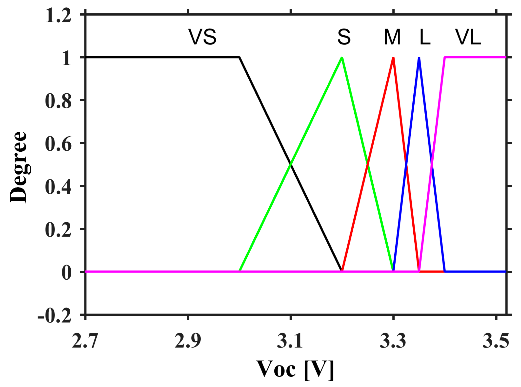
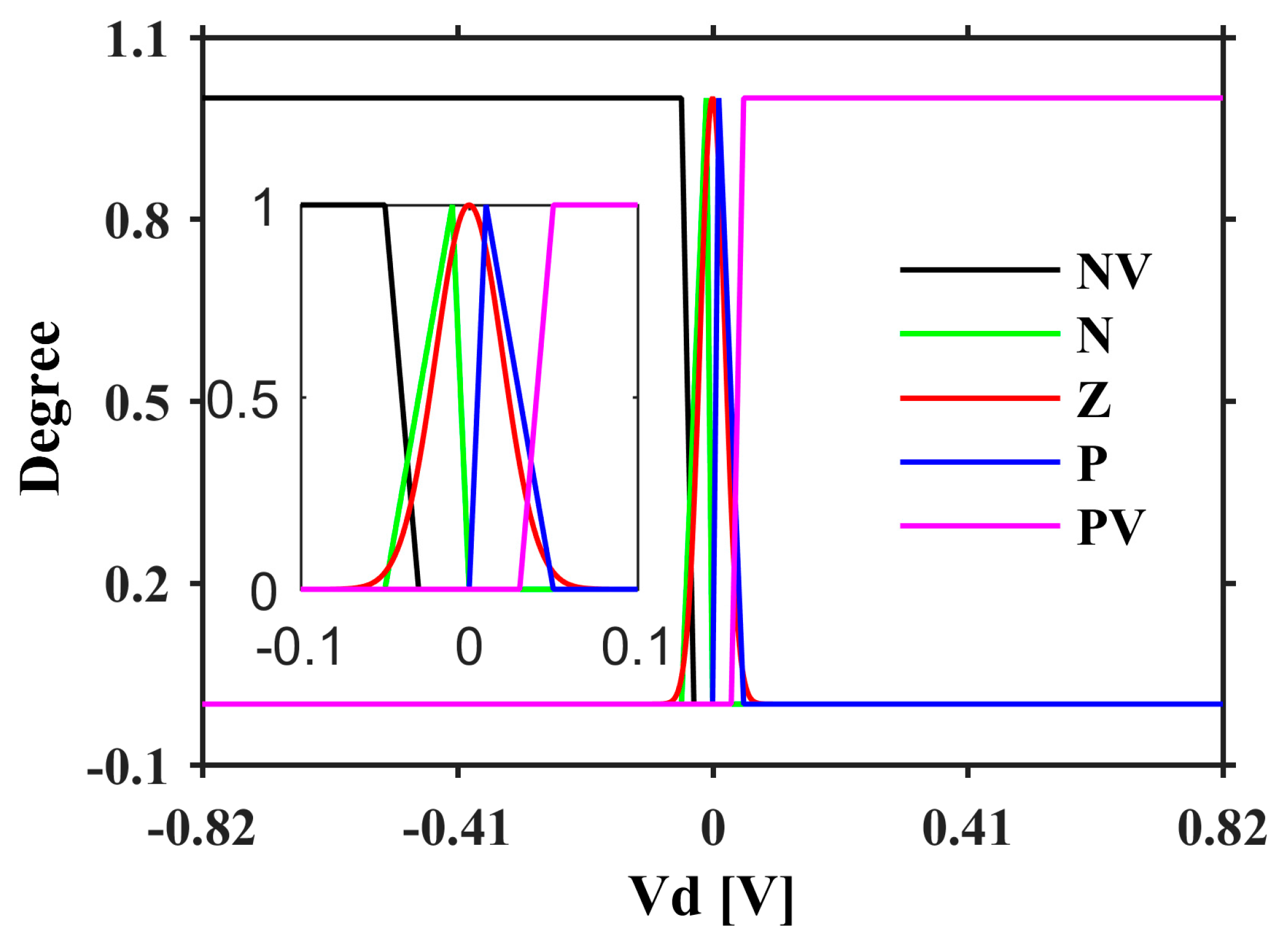
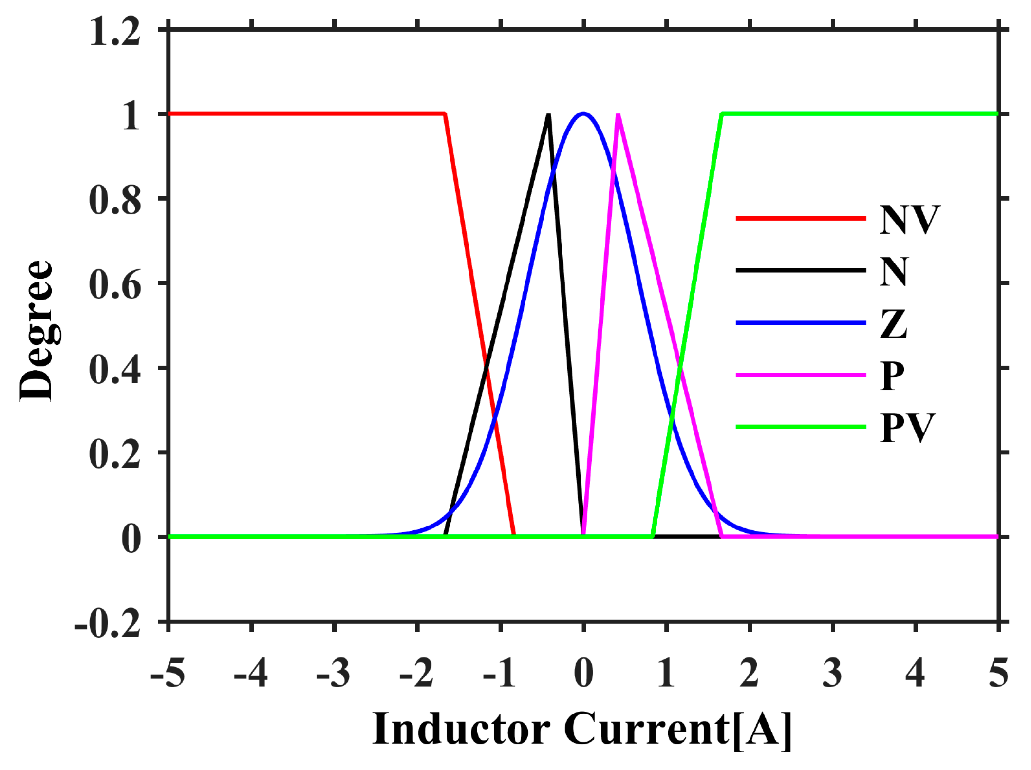
3.1. Membership Functions

A membership function (MF) defines how each point of the variables in the input space is mapped to a degree of membership between 0 and 1. There are two fuzzy input variables, cell OCV ( V o c ) and cell OCV difference ( V d ), and one fuzzy output variable, inductor current ( I L ). The OCV difference of cell i is defined as:
V d i = V o c i V o c i + 1
The membership selection is decided by the characteristics of the battery pack and the requirement of the balancing system. A LiFePO4 battery is used as an example to explain the membership design. The OCV of the LiFePO4 battery is described by five linguistic variables, i.e., VS (very small), S (small), M (medium), L (large), and VL (very large), in triangular and trapezoidal forms, as shown in Figure 7. Since the LiFePO4 battery has a very flat voltage around 3.3 V, the MFs concentrate on 3.3 V. The OCV difference V d and the inductor current I L are described by the same five linguistic variables as the OCV, i.e., NV (negative large), N (negative), Z (around zero), P (positive), and PV (positive large), as shown in Figure 8 and Figure 9, respectively. The V d range covers all the possible cell voltage differences in the pack. However, in most cases, these difference values are between −0.1 V and 0.1 V, which is shown in the enlarged figure. In the control process, the output current should be near zero when the OCV difference is near zero to improve the efficiency and stability, and the output current should increase quickly when the OCV difference is above the threshold to obtain a fast balancing speed. Since the sum of the MFs at one point is not required to be one in the FL system [38], the use of Gaussian MF can achieve better performance than the use of the triangle MF; thus Gaussian MF is applied to the linguistic variable Z for the MFs of V d and I L . It can make the output inductor current drop quickly to near zero when V d is less than 20 mV, reducing the balancing loss and the chance of divergence.

3.2. Fuzzy Logic Controller

The design of the proposed FL controller is explained and the procedure is summarized as follows [39,40].
Step 1: Determination of fuzzy rules. The rules describe the knowledge about the behaviour of a complex system. These rules with two inputs can be generally expressed as:
R k : If   X 1   is   A 1 k   and   X 2   is   A 2 k ,   Then   Y   is   B k    for   k = 1 , 2 ,   ,   n .
where n is the total number of the fuzzy rules and R k denotes the k th rule. A 1 k , A 2 k (k = 1, 2, …, n), and B k (k = 1, 2, …, n) are the fuzzy sub-sets of X 1 , X 2 , and Y, respectively. In this study, X 1 and X 2 are the input linguistic variables V d and V o c , respectively, and Y is the output linguistic variable I L . The detailed fuzzy rules are given in Table 1. These rules describe the relation between the input and output of the FL controller based on the expert knowledge of LiFePO4 battery balancing. There are a total of 25 rules. The following are two of the rules.
  • Rule 01: IF V d = NV and V o c = VS THEN I L = NV;
  • Rule 25: IF V d = PV and V o c = VL THEN I L = PV.
Step 2: Fuzzification of the input variables. Fuzzy sets for the variables are determined by the MFs. The crisp inputs are converted into a degree of membership between 0 to 1 using the following equation:
x i = μ A j k ( x i )
where x i is the input value of i th input variable, and μ A j k ( x ) is the fuzzy MF of the input linguistic variables V d and V o c .
Step 3: Fuzzy inference. This step applies fuzzy rules to map the given inputs to an output fuzzy set with the FL operations. Maximum-minimum composition is utilized. First, the output fuzzy set of each rule is computed with an implication operation, and then all the output sets are combined into a single fuzzy set with an aggregation operation. Mathematically, the process can be written as:
u B k ( I L ) = min [ u A 1 k ( V d ) , u A 2 k ( V o c ) , u B k ( I L ) ] , k = 1 , 2 , n .
u B ' ( I L ) = max [ u B k ( I L ) ]         k = 1 , 2 , n .
where u B ( I L ) denotes the aggregated output fuzzy set.
Step 4: Defuzzification of the output. This step converts the inference fuzzy output set to the crisp inductor current ( I L ). The centre of gravity method is used for defuzzification. It is given by:
I L = u B ( I L ) I L d I L u B ( I L ) d I L
Step 5: Obtain the mode durations for each cell. With the inductor currents, the desired mode durations can be calculated by:
( d 1 d 2 d 3 ) = ( V p R o n 2 I L 1 I L 2 I L 2 + I L 3 I L 3 V p R o n I L 1 + I L 3 V p R o n + I L 1 + I L 3 2 I L 3 V p R o n + I L 2 + 2 I L 3 V p R o n + I L 1 + I L 2 + 2 I L 3 V p R o n + I L 1 + 2 I L 2 + 2 I L 3 ) 1   ( V o c 1 R o n + I L 1 + I L 2 + I L 3 + I L 1 R L R o n V o c 1 + V o c 2 R o n + I L 1 + 2 I L 2 + 2 I L 3 + I L 2 R L R o n V o c 1 + V o c 2 + V o c 3 R o n + I L 1 + 2 I L 2 + 3 I L 3 + I L 3 R L R o n )  

3.3. Adaptivity

The FL controller has good adaptivity due to a membership design that combines triangle MF and Gaussian MF. The inductor current can be regulated based on the feedback of V o c and V d . For example, if V d is large, a high inductor current is desired; if V d is small, a low inductor current is desired. The FL controller can adaptively change the inductor current for different situations.
Considering only V d as the input with the constant OCV at 3.3 V, the equivalent gain and the corresponding inductor current are shown in Figure 10 and Figure 11, respectively. When V d is positively or negatively large, the equivalent gain is small to keep the inductor current under the limit. As V d becomes small, the equivalent gain increases. When V d is about 25 mV, the equivalent gain reaches its peak value of 70, corresponding to the peak inductor current of 3 A. When V d continues decreasing to 15 mV, the equivalent gain starts to decrease sharply to less than 20. At the same time, the inductor current declines to near zero. This prevents the divergence of the already-balanced cells. For comparison, the gain of the PI controller is shown by the dotted line in Figure 10, which has the same peak inductor current.
Considering both V o c and V d as inputs, the inductor currents are shown in Figure 12. When V o c is higher than 3.5 V, representing a SOC higher than 90%, the inductor current is reduced and less balancing current is charged to this cell. When V o c is lower than 3 V (about 20% of the SOC), the inductor current is also reduced and less balancing current is discharged from this cell. This mechanism helps to protect the battery cells and potentially to extend their service life.

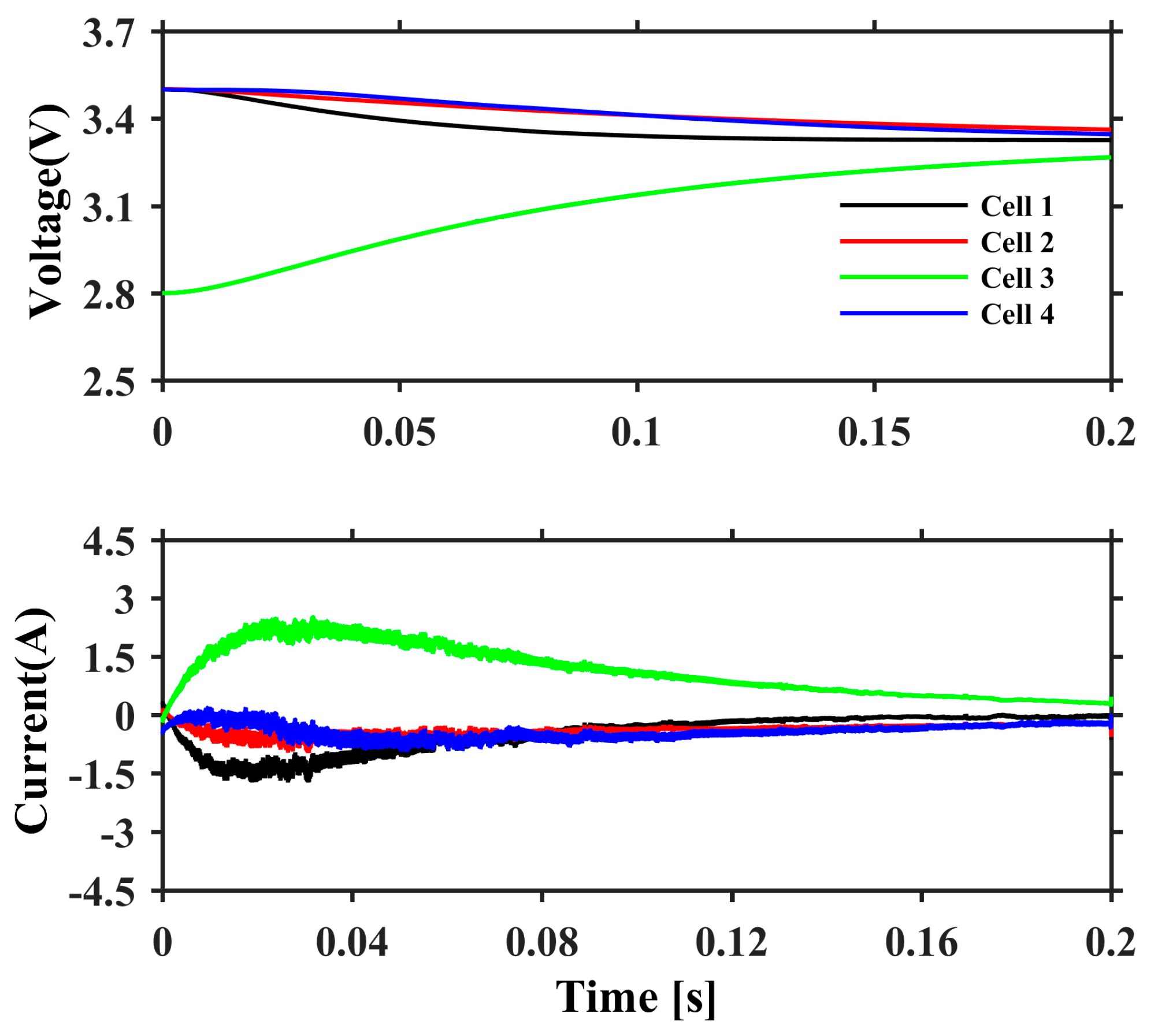
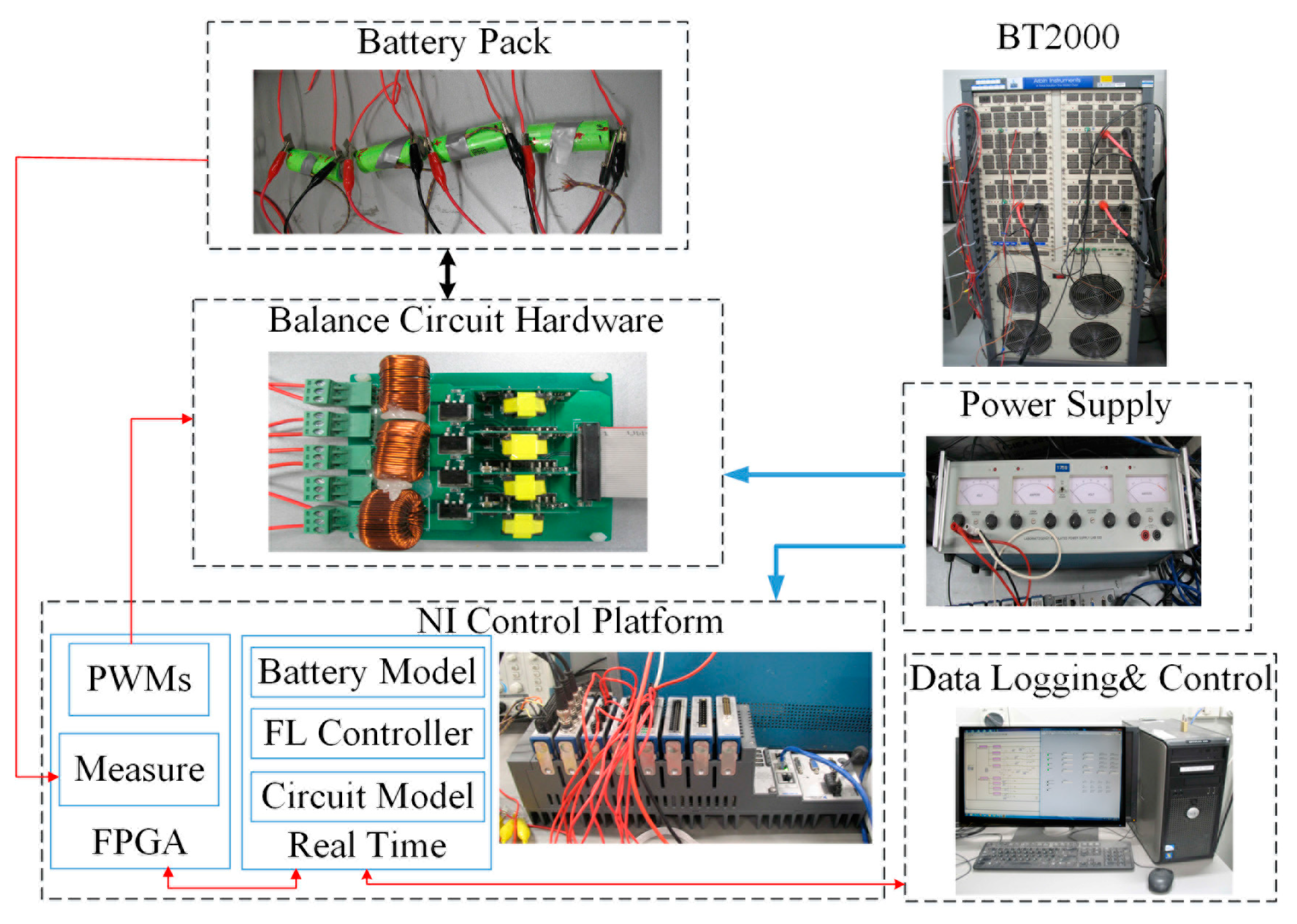
4. Experimental Results

To evaluate its performance, a prototype of the MSIBC was built to balance a four-cell battery pack. A NI FPGA module was used to implement the FL controller for the generation of the pulse width modulation (PWM) to control the MOSFETs in the MSIBC with a frequency of 5 kHz. Initially, all four cells were fully charged using an Arbin BT2000, then one cell in the pack (e.g., cell four in this test) was discharged by 20% of the tested capacity to create an imbalance scenario.
Once the balancing operation was completed, all the four cells were fully charged again with the Arbin BT2000 to evaluate the balancing effects. Figure 13 shows the performance evaluation platform for the MSIBC. In this platform, the PI controller is also implemented. The experimental results of the FL controller were compared with those of the PI controller.
LiFePO4 battery cells from the A123 Company and lithium nickel cobalt aluminum oxide (NCA) battery cells from Samsung were selected in this study. After a screening process, the cells with almost the same internal resistances and capacities in each type were connected in series to make the battery pack. The specifications of these two types of battery cells are listed in Table 2.
The inductor current and the mode duration decide the cell balancing currents based on Equation (1). The highest inductor current was set at 3 A, and the peak battery balancing current was 4 A. The balancing stopped when the OCV difference was less than 10 mV or the balancing time was longer than 3000 s.

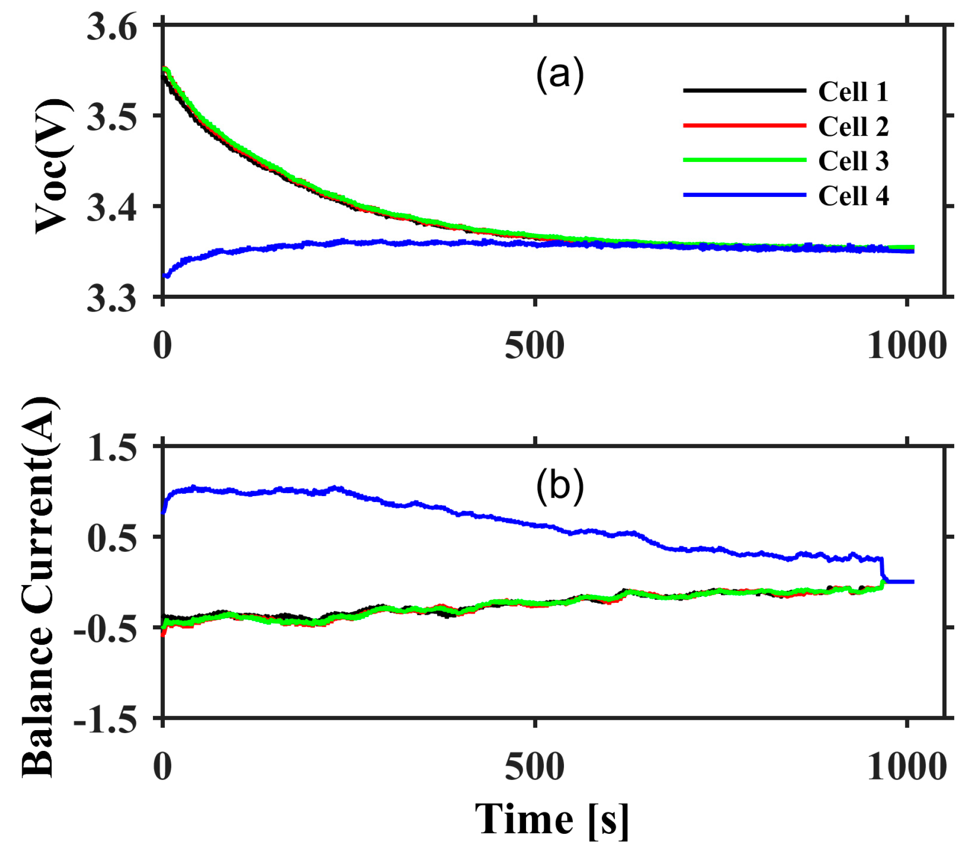
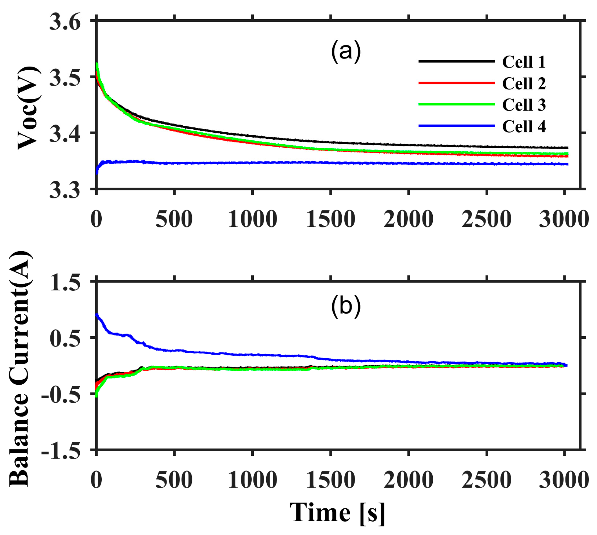
4.1. Experimental Results for LiFePO4 Battery Pack

The LiFePO4 battery has flat voltage characteristics. Figure 14 and Figure 15 show the OCVs and the average balancing currents with the FL and the PI controllers for the LiFePO4 battery cells during the balancing process, respectively.
The balancing operations with the FL controller stopped at around 1000 s when the maximum OCV difference reached 10 mV. In contrast, the balancing operation with the PI controller stopped at about 3000 s. This is because the FL controller maintains a higher balancing current for a longer time than the PI controller, which can be seen in Figure 14b and Figure 15b, respectively. Furthermore, with the FL controller, the three cells with the same initial OCVs keep converging as the gains among them are very small, as shown in Figure 14a. With the PI controller, until the balancing operation runs out of time, there are still significant OCV differences, as shown in Figure 15a, due to the slow balancing speed, which is a result of the small average balancing currents in the balancing process.

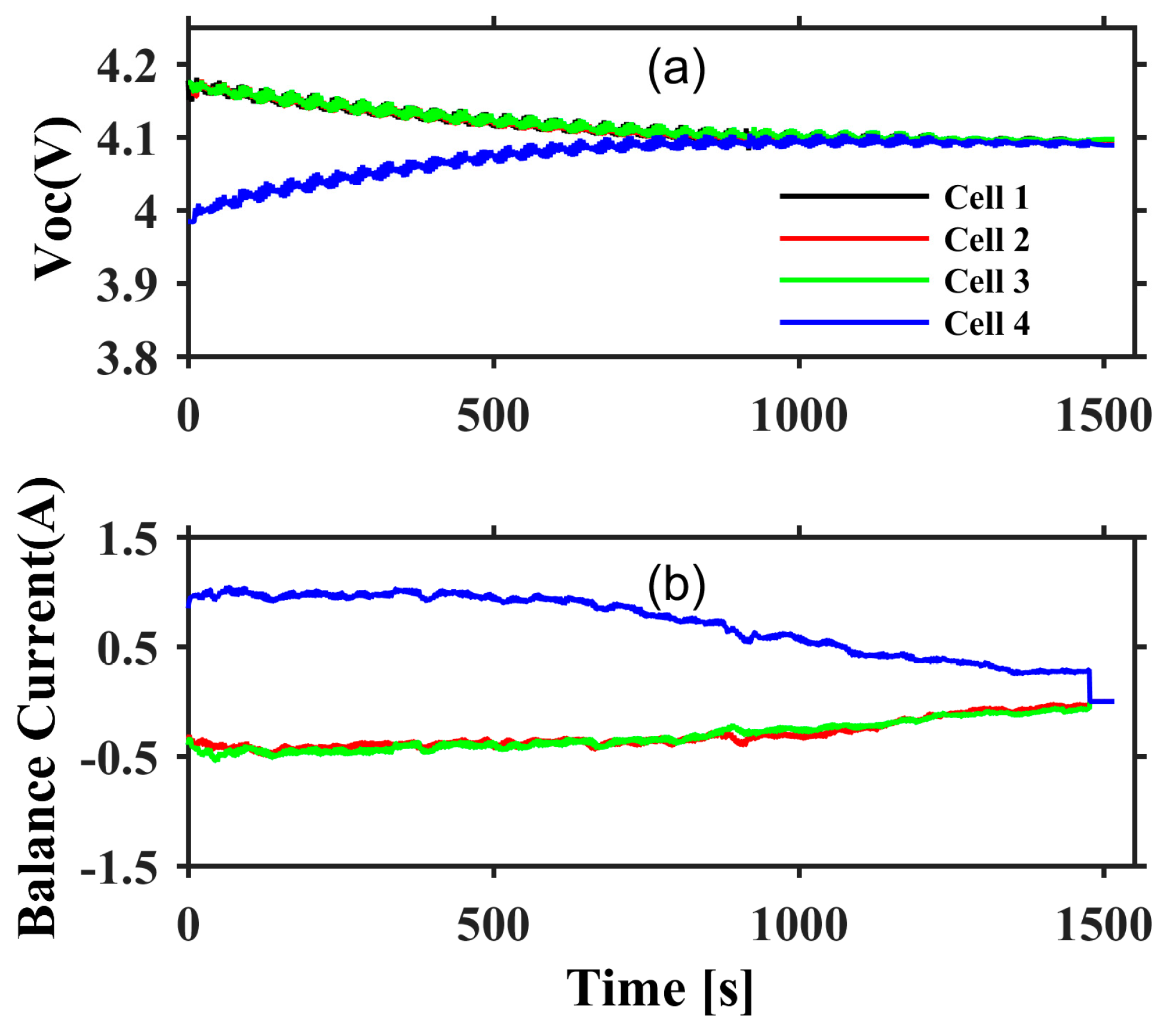
4.2. Experimental Results for NCA Battery Pack

In contrast with the LiFePO4 battery, the NCA battery has steep voltage characteristics. The OCVs and the average balancing currents of the NCA batteries with the FL controller and the PI controller are shown in Figure 16 and Figure 17, respectively. With the FL controller, the balancing ends at 1500 s, when the maximum OCV difference reaches 10 mV. The balancing time for the NCA battery is slightly longer than that for the LiFePO4 battery, since the OCVs of the NCA battery drop slowly compared with those of the LiFePO4 battery. The recovered pack capacity is the highest in all cases, and this is discussed in the next section. With the PI controller, the maximum OCV difference still cannot reach 10 mV within 3000 s. The OCVs drop slowly, and the average balancing currents for the NCA battery are slightly higher than those for the LiFePO4 battery.

5. Discussions

In the experimental results, accurate battery SOC values and the recovered pack capacities are calculated. In a battery pack connected in series, the weakest cell decides the pack capacity. Therefore, the recovered pack capacity (energy) is the ratio of the increased capacity of the weakest cell to the tested capacity (energy). The balancing results for the A123 LiFePO4 battery pack and the Samsung NCA battery pack are shown in Table 3 and Table 4, respectively.
As shown in Table 3, the FL controller has better balancing performance than the existing PI controller in the LiFePO4 battery pack. With the PI controller, the final SOC difference is still 10% and 0.1299Ah is charged to the weakest cell as the recovered pack capacity. With the FL controller, the final SOC difference narrows to 7.5% and 0.17577Ah is charged to the weakest cell as the recovered pack capacity.
In the NCA battery pack, more charges are finally transferred, as shown in Table 4, and the final SOC difference is smaller. With the PI controller, 0.2382 Ah are charged to the fourth battery cell and the final maximum SOC difference is 6.5%. With the FL controller, 0.2989 Ah is charged into the fourth cell and the final maximum SOC difference is only 2.5%, which is the best of all cases. The recovered pack capacities are 0.2382 Ah and 0.2989 Ah for the PI controller and the FL controller, respectively.

6. Conclusions

This paper has presented a FL controller for a low-cost battery pack balancing system based on the MSIBC. The experimental results have demonstrated that the proposed FL controller significantly improves the performance of the MSIBC compared with the existing PI controller. The two controllers were tested with two types of batteries; LiFePO4 and NCA. For the LiFePO4 battery pack, the FL controller for the MSIBC only takes 950 s for pack balancing, which is only a third of the balancing time of the PI controller (3000 s). Furthermore, the FL controller for the MSIBC can recover 2% more pack capacity than PI controller. For the NCA battery pack, the balancing time with the FL controller is only 1450 s, while the balancing time with the PI controller is 3000 s, and the FL controller for the MSIBC can recover 3% more pack capacity than the PI controller. In both cases, more pack capacity was recovered with the FL controller than with the PI controller, which extends the serving time of the battery packs in EVs, due to significant improvement of the balancing performance of the battery pack, and thus reduces the overall cost of EVs.

Acknowledgments

This research work is supported by the Commonwealth of Australia, through Australia Research Council (ARC) Linkage Grant LP110200302.

Author Contributions

Xiudong Cui proposed a new battery pack balancing system, targeting to complete the balancing process before the end of charging, established the experimental platform and conducted the experiments. Yunlei Zhang and Cungang Hu designed and implemented the balancing circuit. Xiudong Cui drafted the manuscript and Weixiang Shen finalized the manuscript.

Conflicts of Interest

The authors declare no conflict of interest.

References

  1. Mulder, G.; Omar, N.; Pauwels, S.; Meeus, M.; Leemans, F.; Verbrugge, B.; De Nijs, W.; Van den Bossche, P.; Six, D.; Van Mierlo, J. Comparison of commercial battery cells in relation to material properties. Electrochim. Acta 2013, 87, 473–488. [Google Scholar] [CrossRef]
  2. Nitta, N.; Wu, F.; Lee, J.T.; Yushin, G. Li-ion battery materials: Present and future. Mater. Today 2015, 18, 252–264. [Google Scholar] [CrossRef]
  3. Cao, J.; Schofield, N.; Emadi, A. Battery balancing methods: A comprehensive review. In Proceedings of the 2008 VPPC IEEE Vehicle Power and Propulsion Conference, Harbin, China, 3–5 September 2008; pp. 1–6. [Google Scholar]
  4. Uno, M.; Tanaka, K. Double-Switch Single-Transformer Cell Voltage Equalizer Using a Half-Bridge Inverter and a Voltage Multiplier for Series-Connected Supercapacitors. IEEE Trans. Veh. Technol. 2012, 61, 3920–3930. [Google Scholar] [CrossRef]
  5. Uno, M.; Kukita, A. Double-Switch Equalizer Using Parallel- or Series-Parallel-Resonant Inverter and Voltage Multiplier for Series-Connected Supercapacitors. IEEE Trans. Power Electron. 2014, 29, 812–828. [Google Scholar] [CrossRef]
  6. Baughman, A.C.; Ferdowsi, M. Double-Tiered Switched-Capacitor Battery Charge Equalization Technique. IEEE Trans. Ind. Electron. 2008, 55, 2277–2285. [Google Scholar] [CrossRef]
  7. Lu, R.; Zhu, C.; Tian, L.; Wang, Q. Super-Capacitor Stacks Management System With Dynamic Equalization Techniques. IEEE Trans. Magn. 2007, 43, 254–258. [Google Scholar] [CrossRef]
  8. Kim, M.-Y.; Kim, C.-H.; Kim, J.-H.; Moon, G.-W. A Chain Structure of Switched Capacitor for Improved Cell Balancing Speed of Lithium-Ion Batteries. IEEE Trans. Ind. Electron. 2014, 61, 3989–3999. [Google Scholar] [CrossRef]
  9. Park, S.-H.; Park, K.-B.; Kim, H.-S.; Moon, G.-W.; Youn, M.-J. Single-Magnetic Cell-to-Cell Charge Equalization Converter With Reduced Number of Transformer Windings. IEEE Trans. Power Electron. 2012, 27, 2900–2911. [Google Scholar] [CrossRef]
  10. Li, S.; Mi, C.C.; Zhang, M. A high efficiency low cost direct battery balancing circuit using a multi-winding transformer with reduced switch count. In Proceedings of the 2012 Twenty-Seventh Annual IEEE Applied Power Electronics Conference and Exposition (APEC), Orlando, FL, USA, 5–9 February 2012; pp. 2128–2133. [Google Scholar]
  11. Li, S.; Mi, C.C.; Zhang, M. A High-Efficiency Active Battery-Balancing Circuit Using Multiwinding Transformer. IEEE Trans. Ind. Appl. 2013, 49, 198–207. [Google Scholar] [CrossRef]
  12. Lim, C.-S.; Lee, K.-J.; Ku, N.-J.; Hyun, D.-S.; Kim, R.-Y. A Modularized Equalization Method Based on Magnetizing Energy for a Series-Connected Lithium-Ion Battery String. IEEE Trans. Power Electron. 2014, 29, 1791–1799. [Google Scholar] [CrossRef]
  13. Shin, J.-W.; Seo, G.-S.; Chun, C.-Y.; Cho, B.-H. Selective flyback balancing circuit with improved balancing speed for series connected lithium-ion batteries. In Proceedings of the 2010 International Power Electronics Conference (IPEC), Sapporp, Japan, 21–24 June 2010; pp. 1180–1184. [Google Scholar]
  14. Imtiaz, A.M.; Khan, F.H. Time Shared Flyback Converter; Based Regenerative Cell Balancing Technique for Series Connected Li-Ion Battery Strings. IEEE Trans. Power Electron. 2013, 28, 5960–5975. [Google Scholar] [CrossRef]
  15. Einhorn, M.; Roessler, W.; Fleig, J. Improved Performance of Serially Connected Li-Ion Batteries With Active Cell Balancing in Electric Vehicles. IEEE Trans. Veh. Technol. 2011, 60, 2448–2457. [Google Scholar] [CrossRef]
  16. Park, H.-S.; Kim, C.-E.; Moon, G.-W.; Lee, J.-H. A Modularized Charge Equalizer for an HEV Lithium-Ion Battery String. IEEE Trans. Ind. Electron. 2009, 56, 1464–1476. [Google Scholar] [CrossRef]
  17. Park, H.-S.; Kim, C.-H.; Park, K.-B.; Moon, G.-W.; Lee, J.-H. Design of a Charge Equalizer Based on Battery Modularization. IEEE Trans. Veh. Technol. 2009, 58, 3216–3223. [Google Scholar] [CrossRef]
  18. Lee, Y.-S.; Cheng, M.-W. Intelligent control battery equalization for series connected lithium-ion battery strings. IEEE Trans. Ind. Electron. 2005, 52, 1297–1307. [Google Scholar] [CrossRef]
  19. Lee, Y.-S.; Cheng, G.-T. Quasi-Resonant Zero-Current-Switching Bidirectional Converter for Battery Equalization Applications. IEEE Trans. Power Electron. 2006, 21, 1213–1224. [Google Scholar] [CrossRef]
  20. Lee, Y.-S.; Duh, J.-Y. Fuzzy-controlled individual-cell equaliser using discontinuous inductor current-mode Cu & circk convertor for lithium-ion chemistries. IEE Proc. Electr. Power Appl. 2005, 152, 1271–1282. [Google Scholar] [CrossRef]
  21. Lee, W.C.; Drury, D.; Mellor, P. An integrated design of active balancing and redundancy at module level for Electric Vehicle batteries. In Proceedings of the 2012 IEEE Transportation Electrification Conference and Expo (ITEC), Dearborn, MI, USA, 18–20 June 2012; pp. 1–6. [Google Scholar]
  22. Ling, R.; Dong, Y.; Yan, H.; Wu, M.; Chai, Y. Fuzzy-PI control battery equalization for series connected lithium-ion battery strings. In Proceedings of the 2012 7th International Power Electronics and Motion Control Conference (IPEMC), Harbin, China, 2–5 June 2012; pp. 2631–2635. [Google Scholar]
  23. Nguyen, N.; Oruganti, S.K.; Na, K.; Franklin, B. An Adaptive Backward Control Battery Equalization System for Serially Connected Lithium-ion Battery Packs. IEEE Trans. Veh. Technol. 2014, 63, 3651–3660. [Google Scholar] [CrossRef]
  24. Cassani, P.A.; Williamson, S.S. Feasibility Analysis of a Novel Cell Equalizer Topology for Plug-In Hybrid Electric Vehicle Energy-Storage Systems. IEEE Trans. Veh. Technol. 2009, 58, 3938–3946. [Google Scholar] [CrossRef]
  25. Cassani, P.A.; Williamson, S.S. Design, Testing, and Validation of a Simplified Control Scheme for a Novel Plug-In Hybrid Electric Vehicle Battery Cell Equalizer. IEEE Trans. Ind. Electron. 2010, 57, 3956–3962. [Google Scholar] [CrossRef]
  26. Park, S.-H.; Kim, T.-S.; Park, J.-S.; Moon, G.-W.; Yoon, M.-J. A new buck-boost type battery equalizer. In Proceedings of the APEC 2009 Twenty-Fourth Annual IEEE Applied Power Electronics Conference and Exposition, Washington, DC, USA, 15–19 February 2009; pp. 1246–1250. [Google Scholar]
  27. Kim, M.-Y.; Kim, J.-H.; Moon, G.-W. Center-Cell Concentration Structure of a Cell-to-Cell Balancing Circuit With a Reduced Number of Switches. IEEE Trans. Power Electron. 2014, 29, 5285–5297. [Google Scholar] [CrossRef]
  28. Phung, T.H.; Crebier, J.-C.; Chureau, A.; Collet, A.; Nguyen, V. Optimized structure for next-to-next balancing of series-connected lithium-ion cells. In Proceedings of the 2011 Twenty-Sixth Annual IEEE Applied Power Electronics Conference and Exposition (APEC), Fort Worth, TX, USA, 6–11 March 2011; pp. 1374–1381. [Google Scholar]
  29. Nishijima, K.; Sakamoto, H.; Harada, K. A PWM controlled simple and high performance battery balancing system. In Proceedings of the 2000 IEEE 31st Annual Power Electronics Specialists Conference, Galway, Ireland, 23 June 2000; pp. 517–520. [Google Scholar]
  30. Mestrallet, F.; Kerachev, L.; Crebier, J.C.; Collet, A. Multiphase Interleaved Converter for Lithium Battery Active Balancing. IEEE Trans. Power Electron. 2014, 29, 2874–2881. [Google Scholar] [CrossRef]
  31. Moo, C.S.; Yao Ching, H.; Tsai, I.S. Charge equalization for series-connected batteries. IEEE Trans. Aerosp. Electron. Syst. 2003, 39, 704–710. [Google Scholar] [CrossRef]
  32. Javier, G.-L.; Enrique, R.-C.; Isabel, M.-M.; Miguel, A.G.-M. Battery equalization active methods. J. Power Sources 2014, 246, 934–949. [Google Scholar] [CrossRef]
  33. Cadar, D.; Petreus, D.; Patarau, T.; Etz, R. Fuzzy controlled energy converter equalizer for lithium ion battery packs. In Proceedings of the 2011 International Conference on Power Engineering, Energy and Electrical Drives (POWERENG), Malaga, Spain, 11–13 May 2011; pp. 1–6. [Google Scholar]
  34. Wu, K.C. Switch-Mode Power Converters: Design and Analysis; Academic Press: Cambridge, MA, USA, 2005. [Google Scholar]
  35. Chen, X.; Shen, W.; Cao, Z.; Kapoor, A. Adaptive gain sliding mode observer for state of charge estimation based on combined battery equivalent circuit model. Comput. Chem. Eng. 2014, 64, 114–123. [Google Scholar] [CrossRef]
  36. Zadeh, L.A. Fuzzy sets. Inf. Control 1965, 8, 338–353. [Google Scholar] [CrossRef]
  37. Luo, M.; Zhang, K. Robustness of full implication algorithms based on interval-valued fuzzy inference. Int. J. Approx. Reason. 2015, 62, 61–72. [Google Scholar] [CrossRef]
  38. Michels, K.; Klawonn, F.; Kruse, R.; Nürnberger, A. Fuzzy Control: Fundamentals, Stability and Design of Fuzzy Controllers; Springer: Berlin, Germany, 2007; Volume 200. [Google Scholar]
  39. Ross, T.J. Fuzzy Logic with Engineering Applications; John Wiley & Sons: Hoboken, NJ, USA, 2009. [Google Scholar]
  40. Zhou, Q.; Wu, W.; Liu, D.; Li, K.; Qiao, Q. Estimation of corrosion failure likelihood of oil and gas pipeline based on fuzzy logic approach. Eng. Fail. Anal. 2016, 70, 48–55. [Google Scholar] [CrossRef]
Figure 1. Multi-switched inductor balancing circuit (MSIBC)-based balancing system with a fuzzy logic (FL) controller.
Energies 10 01034 g001
Figure 2. Control signals of MOSFET.
Energies 10 01034 g002
Figure 3. Operation modes of MSIBC in one cycle.
Energies 10 01034 g003
Figure 4. Simulation results for MSIBC with constant equal mode duration.
Energies 10 01034 g004
Figure 5. Battery equivalent circuit model.
Energies 10 01034 g005
Figure 6. Block diagram of an FL controller of MISBC.
Energies 10 01034 g006
Figure 7. Membership functions of open circuit voltages (OCVs).
Energies 10 01034 g007
Figure 8. Membership function of OCV differences.
Energies 10 01034 g008
Figure 9. Membership function of inductor currents.
Energies 10 01034 g009
Figure 10. Equivalent gain for desired inductor current with input V d at an OCV of 3.3 V.
Energies 10 01034 g010
Figure 11. Inductor current with input V d at an OCV of 3.3 V.
Energies 10 01034 g011
Figure 12. Inductor currents with two inputs of V d and V o c .
Energies 10 01034 g012
Figure 13. Performance evaluation platform for MSIBC.
Energies 10 01034 g013
Figure 14. Experimental results for the LiFePO4 battery pack with an FL controller. (a) OCV for each cell; (b) average balancing current for each cell.
Energies 10 01034 g014
Figure 15. Experimental results for the LiFePO4 battery pack with a proportional-integral (PI) controller. (a) OCV for each cell; (b) Average balancing current for each cell.
Energies 10 01034 g015
Figure 16. Experimental results for the NCA battery pack with an FL controller. (a) OCV for each cell; (b) Average balancing current for each cell.
Energies 10 01034 g016
Figure 17. Experimental results for the NCA battery pack with PI controller. (a) OCV for each cell; (b) Average balancing current for each cell.
Energies 10 01034 g017
Table 1. Rule Base of an FL controller for Linguistic Variables.
Balancing Current V d
NVNZPPV
V o c VSNVNVZZP
SNVNZPPV
MNVNZPPV
LNVNZPPV
VLNZZPVPV
Table 2. Specifications of the two types of Battery cells.
Battery TypeLiFePO4NCA
Manufacture companyA123Samsung
Nominal capacity2.3 Ah2.5 Ah
Tested capacity2.13 Ah2.5 Ah
Internal resistance13 m Ω 22 m Ω
Table 3. Balancing Results for the LiFePO4 Battery Pack.
TitlePI ControllerFL Controller
Charge (Ah)Energy (Wh)Charge (Ah)Energy (Wh)
Cell one−0.0549−0.1933−0.0680−0.2386
Cell two−0.0680−0.2387−0.0717−0.2510
Cell three−0.0656−0.2303−0.0697−0.2444
Cell four+0.1299+0.3675+0.1758+0.5327
Recovered capacity (energy) of cell four6% (5.1%)8.25% (7.4%)
Table 4. Balancing Results for the NCA Battery Pack.
TitlePI ControllerFL Controller
Charge (Ah)Energy (Wh)Charge (Ah)Energy (Wh)
Cell one−0.0801−0.3363−0.1370−0.5750
Cell two−0.1075−0.4516−0.1352−0.5675
Cell three−0.1067−0.4478−0.1325−0.5562
Cell four+0.2382+0.8915+0.2989+1.1466
Recovered capacity (energy) of cell four11.2% (10%)14% (12.74%)

