Article

DC Thermal Plasma Design and Utilization for the Low Density Polyethylene to Diesel Oil Pyrolysis Reaction

1
Faculty of Energy Systems and Nuclear Science, University of Ontario Institute of Technology, 2000 Simcoe Street North, Oshawa, ON L1H 7K4, Canada
2
Faculty of Engineering and Applied Science, University of Ontario Institute of Technology, 2000 Simcoe Street North, Oshawa, ON L1H 7K4, Canada
*
Author to whom correspondence should be addressed.
Energies 2017, 10(6), 784; https://doi.org/10.3390/en10060784
Submission received: 25 December 2016 / Revised: 30 May 2017 / Accepted: 31 May 2017 / Published: 7 June 2017
(This article belongs to the Special Issue Energy Production Systems)

Abstract

:
The exponential increase of plastic production produces 100 million tonnes of waste plastics annually which could be converted into hydrocarbon fuels in a thermal cracking process called pyrolysis. In this research work, a direct current (DC) thermal plasma circuit is designed and used for conversion of low density polyethylene (LDPE) into diesel oil in a laboratory scale pyrolysis reactor. The experimental setup uses a 270 W DC thermal plasma at operating temperatures in the range of 625 °C to 860 °C for a low density polyethylene (LDPE) pyrolysis reaction at pressure = −0.95, temperature = 550 °C with τ = 30 min at a constant heating rate of 7.8 °C/min. The experimental setup consists of a vacuum pump, closed system vessel, direct current (DC) plasma circuit, and a k-type thermocouple placed a few millimeters from the reactant sample. The hydrocarbon products are condensed to diesel oil and analyzed using flame ionization detector (FID) gas chromatography. The analysis shows 87.5% diesel oil, 1,4-dichlorobenzene (Surr), benzene, ethylbenzene and traces of toluene and xylene. The direct current (DC) thermal plasma achieves 56.9 wt. % of diesel range oil (DRO), 37.8 wt. % gaseous products and minimal tar production. The direct current (DC) thermal plasma shows reliability, better temperature control, and high thermal performance as well as the ability to work for long operation periods.

1. Introduction

Nowadays plastic consumption is increasing exponentially and the annual consumption of plastics in Europe is about 60 million tons, of which 40% are used in packing and packaging [1]. The excellent properties of plastics have been used to replace the use of wood and metals thus increasing the annual plastic consumption about 20 times from around 5 million tons in the 1950s to nearly 100 million tons in 2011 [2]. It was also reported that 33 million tons of plastic waste are generated in the U.S. based on 2013 statistics [3]. Most recycled plastics are mechanically recycled, while less than 2% is chemically recycled [4]. Growing worldwide concerns regarding the environmental consequences of heavy dependence on fossil fuels, particularly climate change, are likely to constrain excessive use of fossil fuels in the near future. Thus, plastic to oil pyrolysis could have a positive environmental impact by providing alternative fuels and reducing the carbon footprint of incineration [5]. Also, the steady increase in energy consumption coupled with environmental pollution promotes the evolution of alternative fuels such as plastic pyrolysis oil. Because of the increasing cost and decreasing space of landfills, traditional methods of plastic waste recycling such as landfilling and incineration cause irreversible environmental problems, including high NO2 and CO2 emissions [6]. In this research work diesel range oil (DRO) in range of C10–C28 is produced by pyrolysis of plastics and identified using a GC-FID method applied to methanol solutions.
Thermoplastic pyrolysis is a tertiary recycling method that produces liquid hydrocarbons in an inert thermal cracking chemical reaction [7]. The pyrolysis chemical reactions involve scission of long chain polymers to smaller chains forming hydrocarbon products in the C4–C40 range [8]. Polyethylene is a major plastic component and was used as a feedstock for our experimental work. Oils produced from plastic pyrolysis have non-acidic, sulphur-free and non-corrosive characteristics, which is a major advantage of pyrolysis oils over fossil fuels and they can be used as feedstock in fluid catalytic cracking (FCC) refinery units [9,10]. Pyrolysis final products are affected by reaction parameters such as operating temperature, residence time, operating pressure, heating rate and catalysts [11].
In pyrolysis, the polymeric materials are heated to high temperatures causing the macromolecular structures to break down into smaller molecules forming a wide range of hydrocarbons as [12,13]. Polyethylene is chosen since it is a major component of plastic waste from domestic disposal. Many studies have been conducted on the reaction kinetics of plastic wastes to determine rates of polymer conversion against heating rate and operating temperature [14]. As seen in Table 1, the operating temperature is inversely proportional to residence time. Below are the first order reactions used [15]:
Pyrolysis reaction conversion
α =   w o w t w o w
First order reaction:
dx dt = k   ( 1 x )
Reaction constant:
k = k o exp ( E a RT )
The LDPE reaction order can be assumed as n = 1 while the Ea varies with molecular weight of sample [16]. LDPE pyrolysis activation energy is estimated at 179–188 KJ/mol [14]. LDPE pyrolysis has less environmental impact, unlike the incineration of plastics which releases toxic and harmful emissions such as 5.04 CO2 kg/LDPE kg [17,18]. Combustion of pyrolysis oils releases less CO2 in comparison with LDPE incineration, with an average of 6 to 11.5% wt. % (i.e., 0.06–0.115 kg CO2/kg of combusted pyrolysis oil) depending on the engine load [19].
As seen below, as the operating temperature increases, the residence time decreases due to the higher rate of thermal cracking [10]. The chosen residence time in the experimental work is 30 min since thermal plasma has the ability to achieve a temperature higher than 500 °C in that period. As seen in Table 1, the operating temperature is inversely proportional to the residence time.
In this research work, slow pyrolysis is used with a residence time of 30 min without using a catalyst [5]. The minimum cracking temperature of LDPE is 450 °C The main pyrolysis products derived from polyethylene plastics are 1-alkenes, n-alkanes, and α,ω-dialkenes ranging from C1 to C45+ [20]. The repetitive molecular structure of a low density polyethylene (LDPE) chain is shown in Figure 1, below:
The hydrocarbon liquids produced were analyzed by a FID-GC method using methanol as a solvent [13]. The expected pyrolysis products are shown in Figure 2, including the following hydrocarbon fractions:
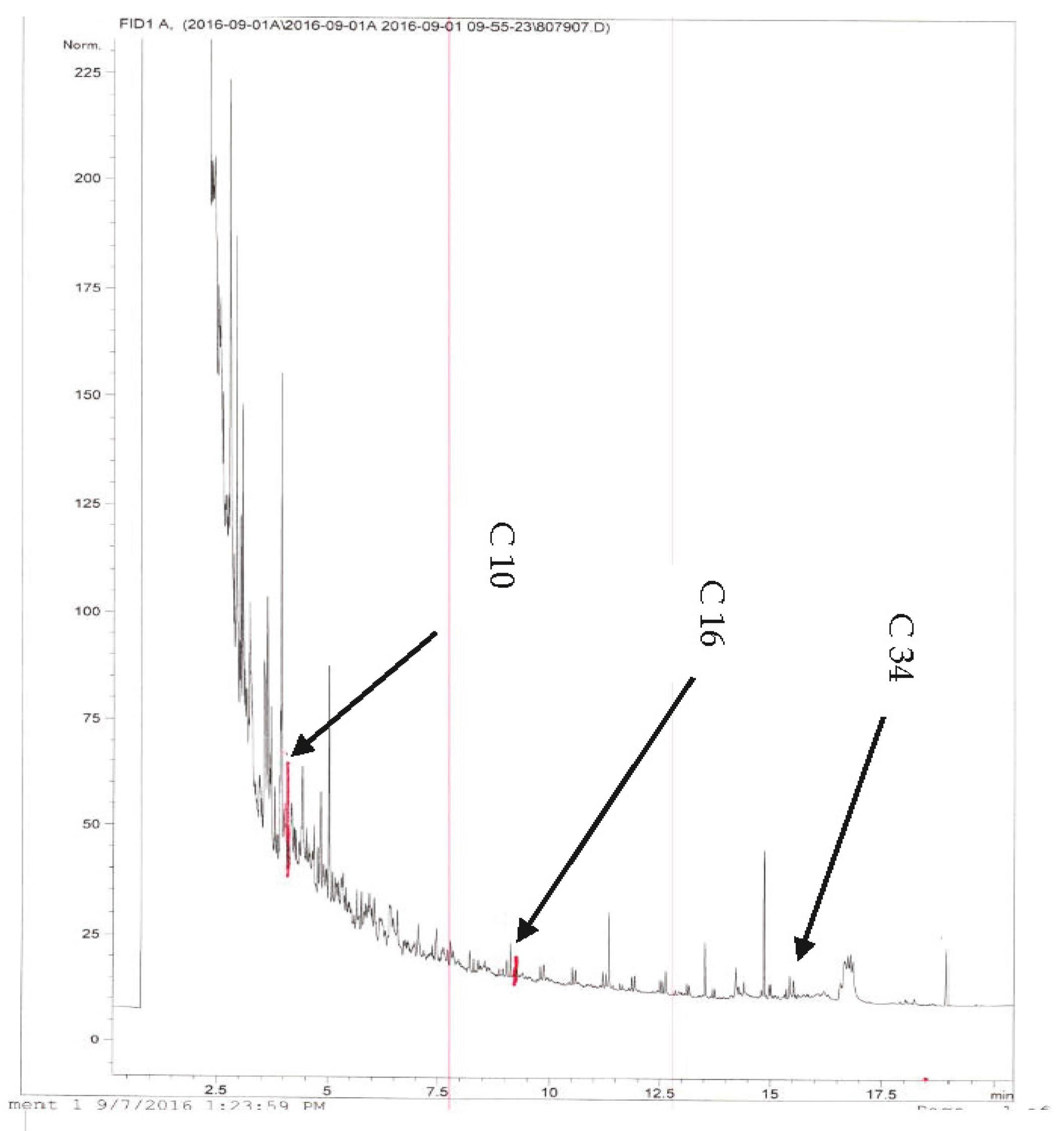
  • Fraction 1: C6 to C10 hydrocarbon liquid
  • Fraction 2: C10 to C16 hydrocarbon liquid
  • Fraction 3: C16 to C34 hydrocarbon liquid
  • Fraction 4: C34 to C50 hydrocarbon liquid

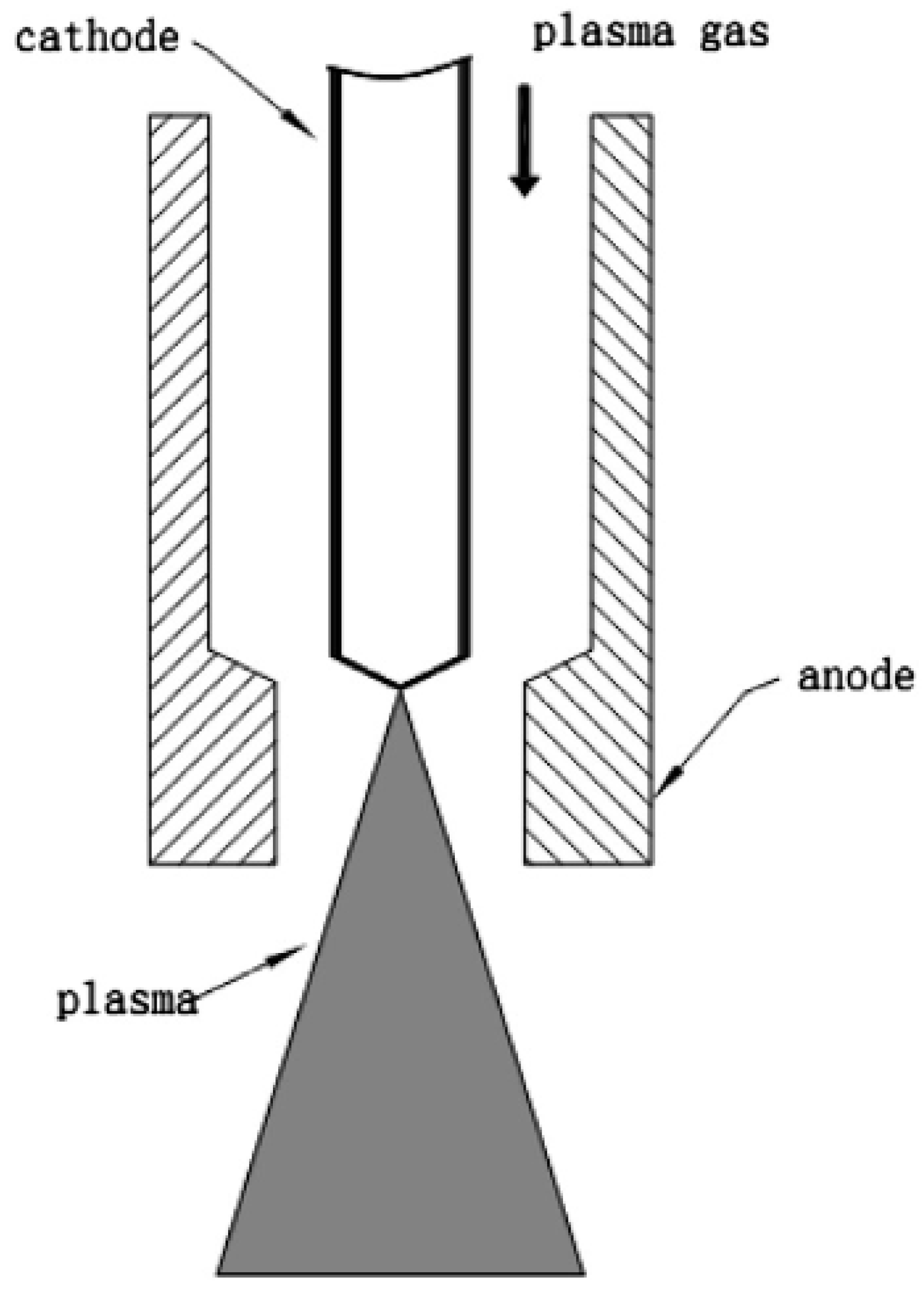
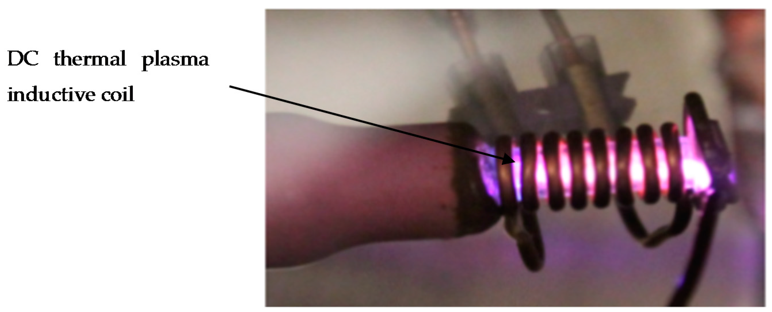
1.1. DC Thermal Plasma

Thermal plasma technology has been under active development and is well-established in metallurgical processing and material synthesis. Thermal plasmas can achieve high temperatures through plasma torches and have the ability to decrease the reactant volume to non-leachable residue [23]. The classification of the thermal plasma used in our project is low temperature plasma (quasi-equilibrium plasma) in the temperature range of 2 × 10³–3 × 10⁴ K, as shown in Table 2.
Thermal plasma technology can help develop pyrolysis reactors due to its ability to generate free radicals which accelerate chemical reactions and thermal cracking rates, causing better reaction kinetics [23,24]. Plasma-assisted chemical reactions are more energy efficient with less environmental impact and in addition, they increase the process stability and enhance the pyrolysis chemistry [25]. A constant heating rate in plastic pyrolysis achieves higher oil yield, and lower gas and tar yield [26]. The thermal plasma can achieve better process chemistry control due to its high energy density, free radical reactivity and rapid startup and shutdown capability [27]. Thermal plasmas can also achieve high thermal efficiencies of up to 70%, as well as long electrode lifetimes (up to 1000 h) which in the long term can justify the high initial capital cost [27].
DC plasma provides a high energy density and high temperature generation between two electrodes and in the presence of a sufficiently high gas flow, the plasma extends beyond one of the electrodes in the form of a plasma jet. In a non-transferred arc torch, the two electrodes do not participate in the process and have the sole function of plasma generation, unlike the transferred arc torch which is only suitable for conductive reactants [24]. Using thermal plasma in plastic waste reactions achieves better environmental performance as well as better life cycle assessment and higher process efficiency [28]. The thermal plasma also accelerates reaction kinetics and improve thermal cracking and the emission enthalpy can be adjusted easily by electric power tuning [29]. Therefore, DC thermal plasma torches can act as a catalyst due to their excellent properties such as high energy density, high temperature range, and high chemical reactivity [30]. Figure 3 shows a non-transferred thermal DC plasma torch schematic diagram.
The advantage of DC thermal plasma is the ease of operation, expected thermal efficiency of 90% and a possible disadvantage of small jet volume [31]. The thermal plasma used in this research work releases thermal energy as arc discharge [24]. The DC thermal plasma used in the experiment is a low temperature thermal plasma with an initial steep ramp in the first minute from 25 to 625 °C, followed by a constant heating rate of 7.8 °C/min.

1.2. Goal and Scope

The goal of this study was to demonstrate a reliable DC thermal plasma system that provides enough thermal energy (approximately 1047 KJ/kg) for pyrolysis reactions. The pyrolysis reaction is allowed to proceed for τ = 30 min and the hydrocarbon products obtained are condensed using a cooling water condensation system at 25 °C. The oil sample is analyzed using FID-gas chromatography and its chemical components are identified. The objective of the experiment is to assess the DC thermal plasma’s ability to work in a LDPE pyrolysis reaction system.

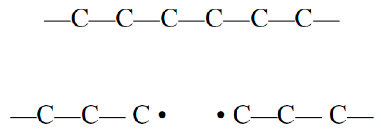
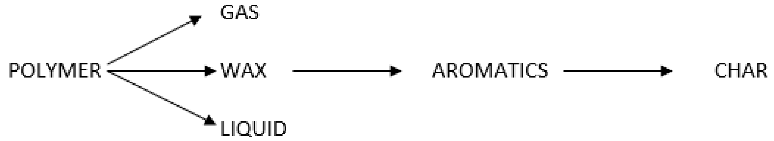
1.3. LDPE Degradation Mechanism

The dissociation during thermoplastic pyrolysis involves free radical transfer through three steps: random scission, free radical saturation and group transfer and the rate of these reactions increases under higher operating temperatures. The first step involves long chain polymer cracking into smaller chains, including shorter chains like methane and ethane that includes free radicals. The second step involves side group saturation leaving free radicals in the middle carbons of the polymer. The final step is chain termination by adding an R group as seen below (Figure 4) [32]:
The pyrolysis reaction as seen above is initiated by breaking weaker bonds producing shorter chains with free radicals. The second step aims to have more stable intramolecular arrangements by hydrogen transfer to free radicals, while the third step involves R group addition and formation of smaller hydrocarbon molecules.

2. Methodology

In order to test the thermal performance of DC thermal plasma in pyrolysis reactors, Step 1 involves gathering reaction kinetics and thermal energy required by thermal plasma jet which includes understanding chemical and physical properties of LDPE, activation energies and reaction constant, k. In Step 2, the DC thermal plasma circuit is designed to achieve the operating temperature required by LDPE pyrolysis. Step 3 includes experimental work in an inert reactor, followed by yield calculations and GC-FID analysis of the pyrolysis oil collected from LDPE. In this step, the LDPE operating conditions are gathered, including optimum cracking temperature, reaction residence time, heating rate, expected product yield, chemical composition of oil produced, and dissociation or thermal energy needed per kg of LDPE. The first order reaction is derived from Equation (2) to anticipate mass loss per unit time for the batch reactor. Step 3 involves experimental setup of main equipment, operating procedure, oil products collection and FID-GC chemical analysis.

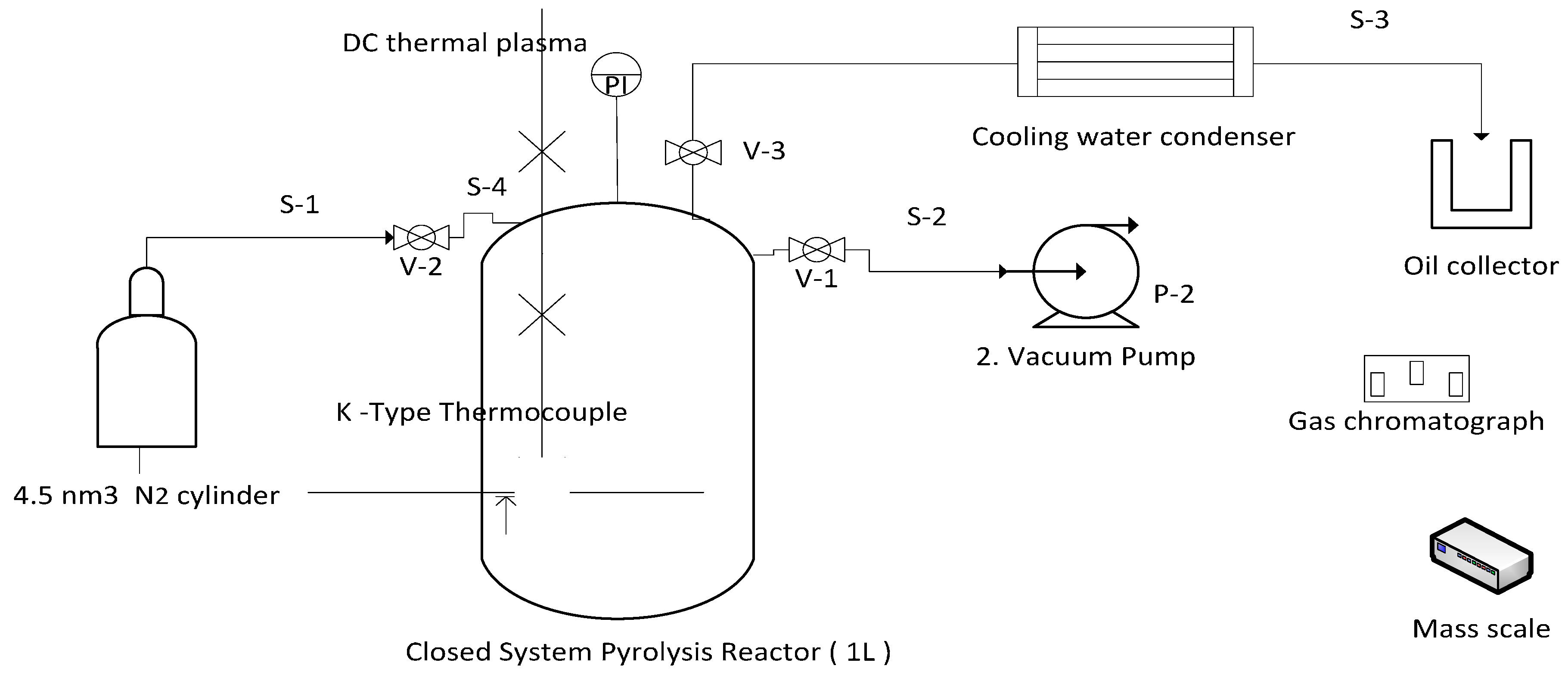
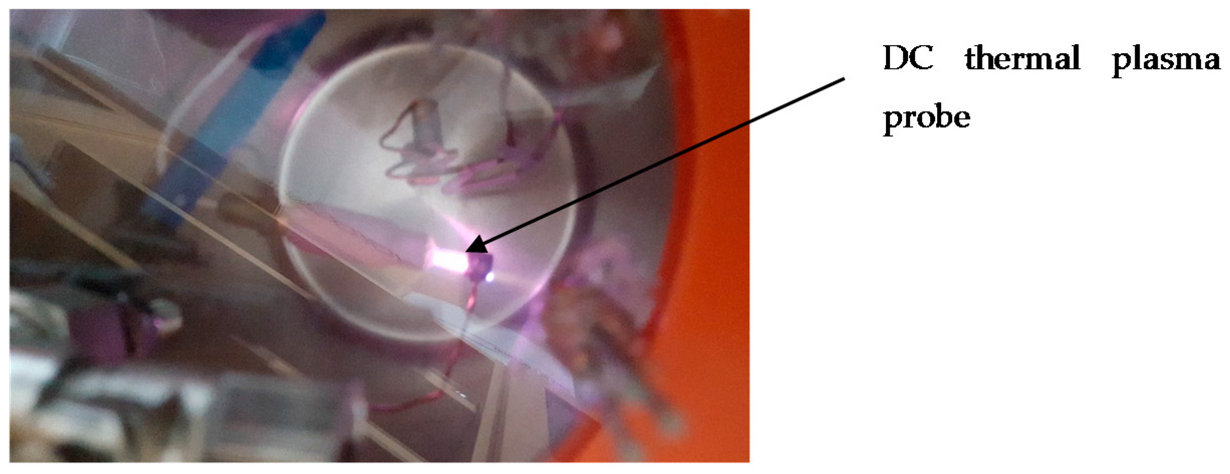
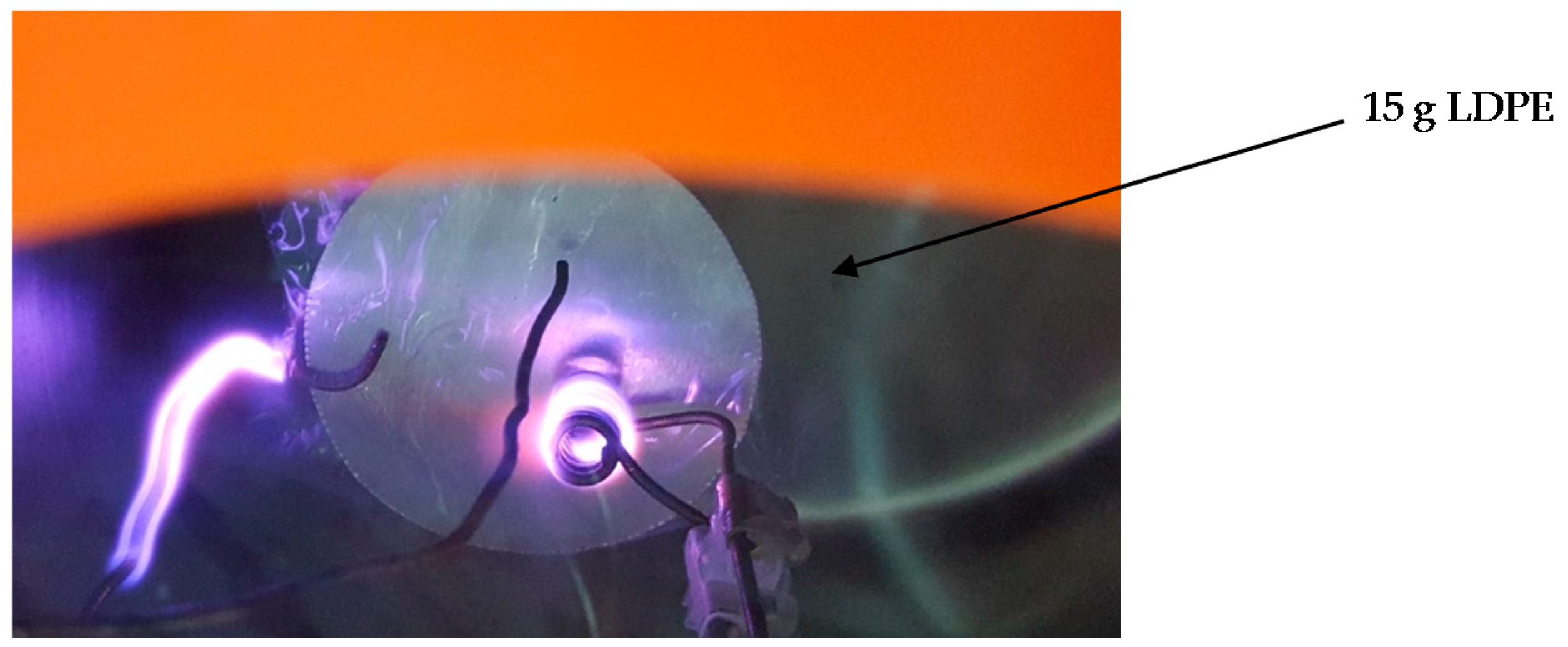
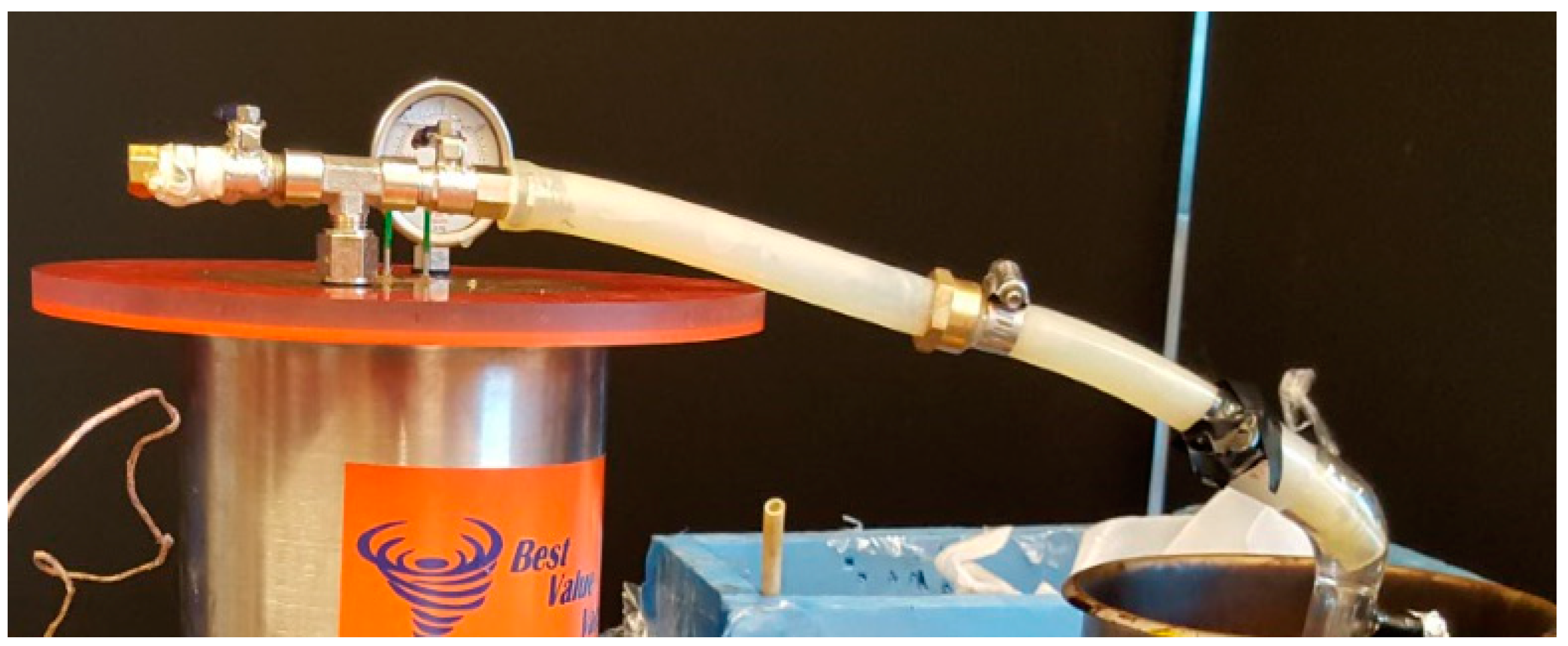
3. Experimental Setup

The experimental setup converts LDPE into oil using a DC thermal plasma as a heating source in a pyrolysis reaction at pressure = −0.95 bar and temperature = 550 °C which is maintained throughout the reaction. The equipment used in the pyrolysis reactor setup is described below in Figure 5.
Vacuum Pump: All other valves should be closed and V-1 opened before starting the experiment. The vacuum pump is used to remove air before nitrogen supply to reactor.
Pure Nitrogen Gas Cylinder: All other valves should be closed and V-2 opened before allowing nitrogen gas to flow to the reactor at 2 bar. The vessel is filled with nitrogen till the pressure increases from −0.95 bar to 1 bar.
Condensation System: The condensation system cools gaseous hydrocarbon products at a constant rate of 35 °C/min. The thermal plasma system is switched off before starting the condensation process.
K-Type Thermocouple: A k-type thermocouple is inserted inside the closed vessel to get an accurate temperature profile. The thermocouple has an initial temperature of 23.5 °C before starting the experiment. The temperature profile is measured per min for 30 min.
DC Thermal Plasma: A 270 W thermal plasma probe at the top of the reactor is used as the heating source on a 15 g LDPE sample and the temperature profile is recorded using the k-type thermocouple. Both electrodes are 316 L stainless steel in a non-transferred thermal plasma setup (i.e., both electrodes are inside the reactor and have a sole plasma generation function) in a nitrogen atmoshphere. The direct current thermal plasma setup is not cooled by any cooling fluid but rather operates under pure nitrogen gas.

3.1. Operating Conditions

In non-catalytic LDPE pyrolysis, light oil starts to form at a low reaction temperature of 430 °C The reaction temperature and reaction residence time τ have an impact on the product yield and the composition of the oil produced. At 550 °C, under a nitrogen atmosphere, polyethylene can form 93 wt. % oil and 7 wt. % gas under optimum conditions [33]. In order to minimize undesired products, nitrogen gas is used and any leak or rupture is avoided. When LDPE pyrolysis is performed at an operating temperature of 500 °C, the liquid yield obtained is 75.6 wt. %. The main components expected of LDPE are benzene, toluene, xylene, dimethyl-benzene, trimethyl-benzene, indane, indene, methyl-indenes, naphthalene, methyl-naphthalenes, ethyl-naphthalene, and other naphthalene derivatives [34]. A slow heating rate and longer reaction residence time maximizes char production, while char content also increases with higher operating temperatures [35]. Oxidation and combustion is avoided and its occurrence can increase char by up to 40–55 wt. % [35]. Since the reaction residence time is longer than few seconds, a batch reactor or pressurized batch reactor is used. In the case of catalyst usage, a fluidized bed reactor is used [35]. The heating rate has a direct impact on tar production and the stability of the pyrolysis oil produced. Thus, recommended heating rates are between 6 to 10 °C/min. Advantages of a batch reactor are a high conversion rate and stable hydrocarbon products [36]. Disadvantages of a batch reactor include batch to batch product variability, high labor cost per batch and the difficulty of large scale production due to the extended residence time [3].

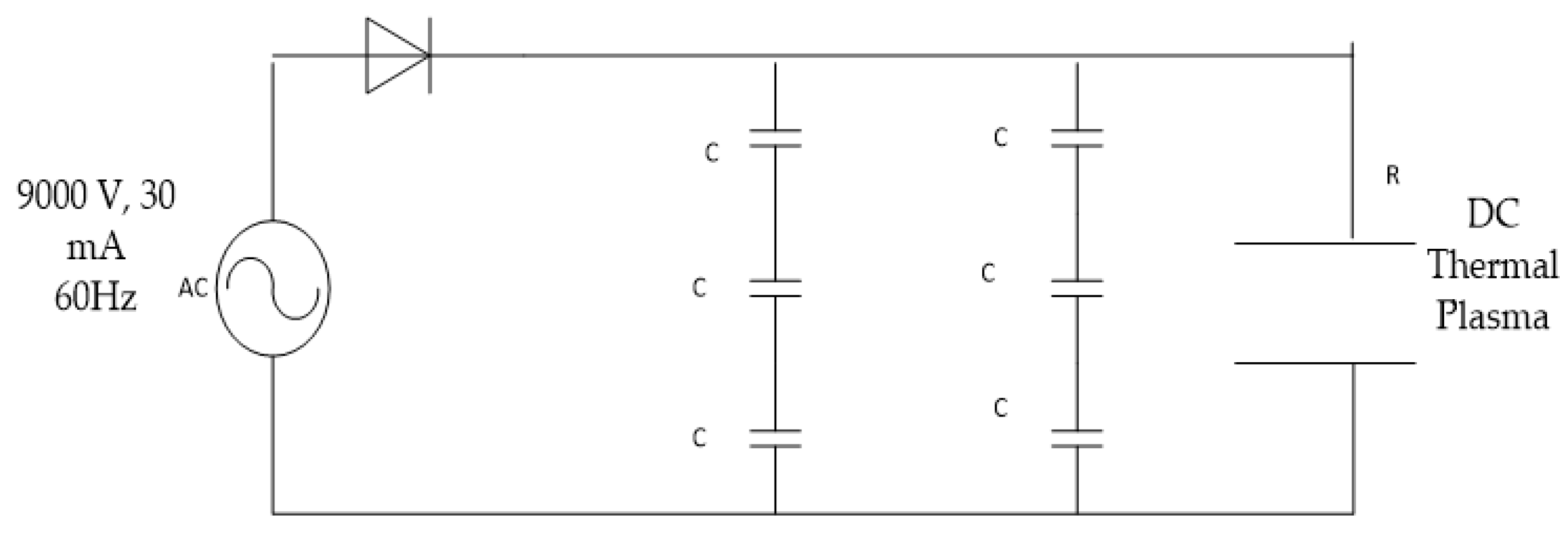
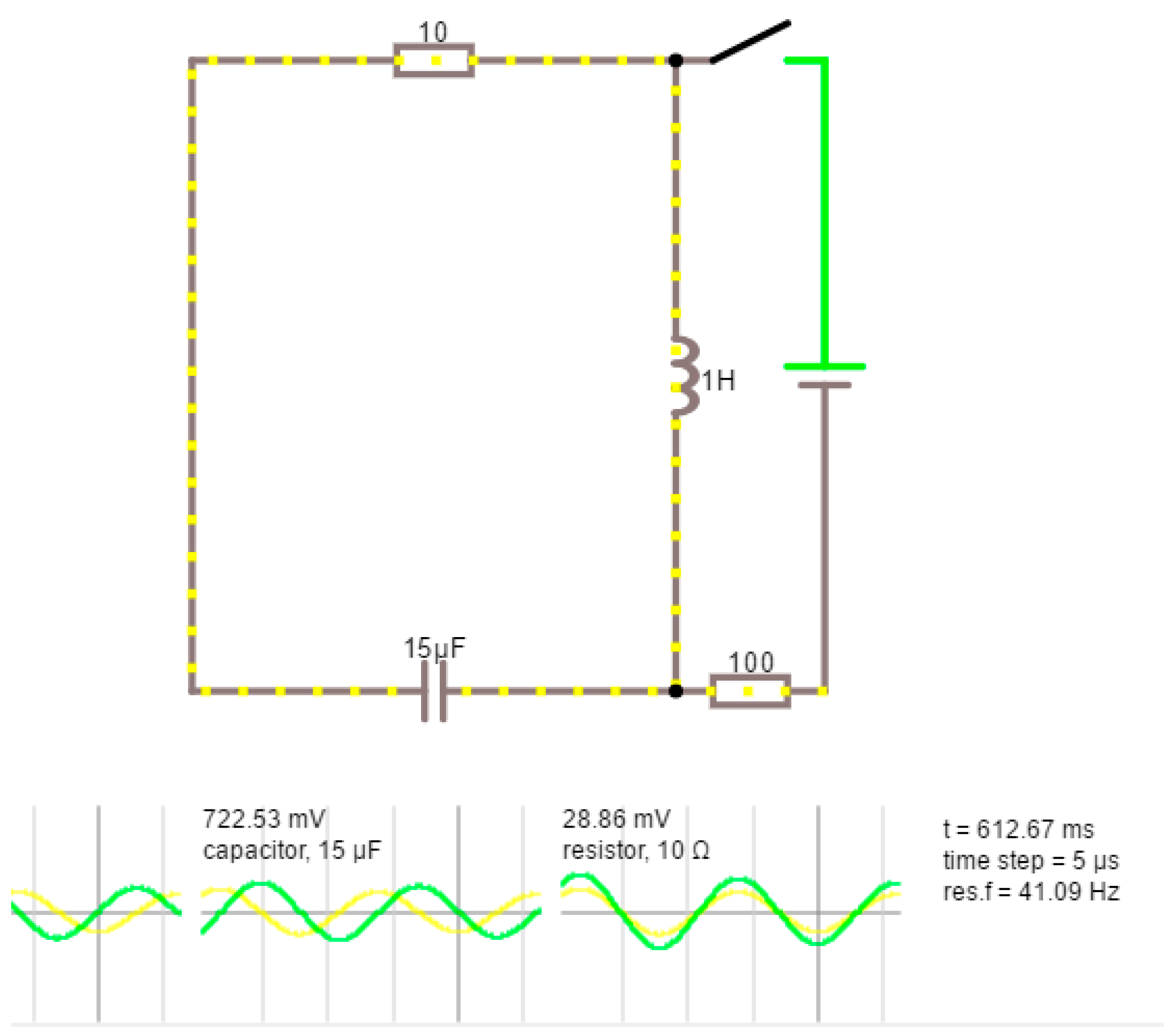
3.2. DC Thermal Plasma Circuit Design

A non-transferred DC circuit of 9000 V, 30 mA at 60 Hz frequency is shown in Figure 6. The circuit consists of capacitors, ceramic plates, diode and resistors. The input power source of the thermal plasma circuit is alternating current (AC), which is converted to direct current and the output impulse power is 270 W.
As shown above, C stands for capacitors, each of which has 1500 pF in two parallel loops connected to a diode that restricts the current to pass to the capacitors which store the electric energy. The thermal plasma circuit has three capacitors with 1500 pF each in series. The total circuit capacitance is shown below:
1 C T   =   1 1 C 1   + 1 C 2   + 1 C 3    
Using the above equation to calculate the total capacitance of three 1500 pF capacitors in series:
1 C T =   1 1 1500 pF +   1 1500 pF + 1 1500 pF   =   500   pF
Thus the total capacitance in the two parallel loops is 1000 pF (i.e., 1 nF). Energy density emitted by DC thermal plasma over emission volume of 3.14 × 10⁻⁷ m3 is calculated below [37]:
E capacitance = 1 2   CV 2   =   ½   × 1000 × 10 12 × 9000 2 = 0.04 J   = 0.129   MJ / m 3
The density of LDPE is 0.92 g/cm3 [38] so the volume of a 15 g sample is 16.3 cm3. The thermal energy needed for the reaction sample is 15.705 KJ. Thus, the energy released by the 270 W DC thermal plasma system satisfies the energy required.
The function of the diode is to convert the alternating current to direct current for thermal plasma generation creating a half wave rectifier as shown below in Figure 7. A half cycle is used to charge the capacitors, and in the response time of absence of current, the capacitors release the charge load at the electrodes generating a thermal plasma torch at the vacuum operating pressure of −0.95 bar.
Imax × Vmax
Imax = 30 mA, Vmax = 9000 V
The thermal plasma impulse power is calculated: PImpulse: 270 W. A K-type thermocouple installed few millimeters away from the LDPE sample shows 625.6 °C as an initial temperature and a maximum temperature of 890 °C is achieved. The temperature profile is presented in the Results section. Thermal plasma can achieve very high temperatures and special precautions need to be taken for safety and health standards [39]. The temperature limit for the experiment is set to 1000 °C. Several precautions should be taken is a higher temperature is detected using the K-type thermocouple:
  • Switching off the main power supply.
  • Pressure test before switching on the thermal plasma system to prevent leaks during operations.
  • Ensure the pressure is below atmospheric for optimum plasma operation.

4. Experimental Results

As seen below, a 270 W thermal plasma operating at a pressure = −0.95 bar using non-transferred DC thermal plasma in an inert vacuum chamber over a ceramic nozzle as shown in Figure 8 and Figure 9.
The DC thermal plasma is integrated inside a 1 L pyrolysis reactor and tested on a 15 g LDPE sample. After few min the LDPE sample shrinks and changes into molten plastic, followed by formation of gaseous hydrocarbon products. The gaseous products are allowed to condense into oil products. In Figure 10, DC thermal plasma emissions on a 15 g LDPE setup is shown.
At the end of the reaction, the gaseous hydrocarbon products are allowed to escape at atmospheric pressure through a condensation system to form liquid hydrocarbons and waxes are allowed to condense as shown in Figure 11 and identified using GC-FID.

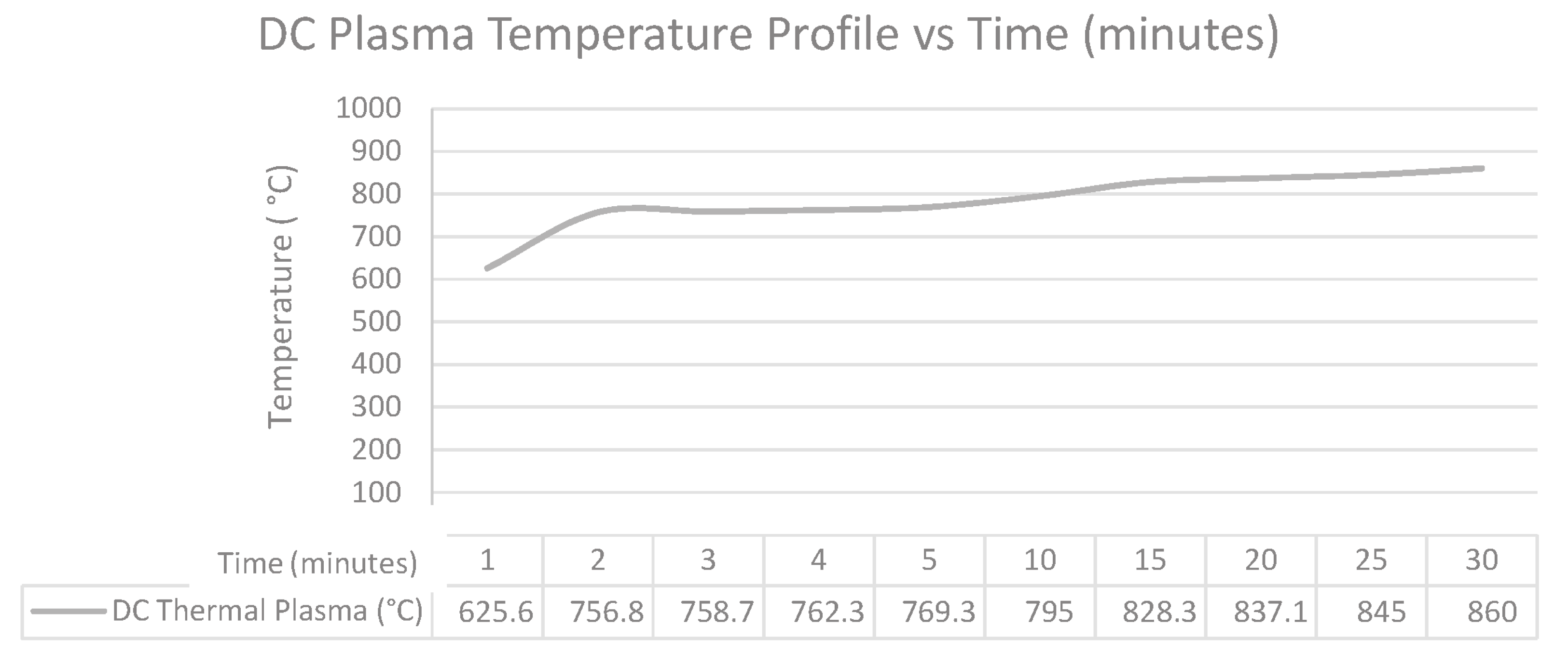
4.1. Temperature Profile

The temperature profile is recorded using the K-type thermocouple for the DC thermal plasma. As seen in the temperature profile, the initial temperature reading is 625.6 °C and a maximum temperature of 860 °C is reached. The thermal plasma showed an acceptable gradual temperature increase which is favored in LDPE pyrolysis.
As seen in Figure 12, the DC thermal plasma produces a high temperature profile on the 15 g thermoplastic sample and can be easily controlled by the current input to the plasma circuit. It can also be concluded that the DC thermal plasma with 270 W can achieve higher temperatures than required for pyrolysis (up to 860 °C).

4.2. Collection of Oil Samples

The hydrocarbon gaseous products from the pyrolysis experiment pass through a condensation system and the volatile oil sample is analyzed using FID gas chromatography. The oil sample collected from a 15 g sample of LDPE and condensed oil is shown in Figure 13.
The hydrocarbon gaseous products are condensed and the liquid products are collected using potable cooling water at 25 °C at a cooling rate of 35 °C/min for 15 min as shown in Figure 15.

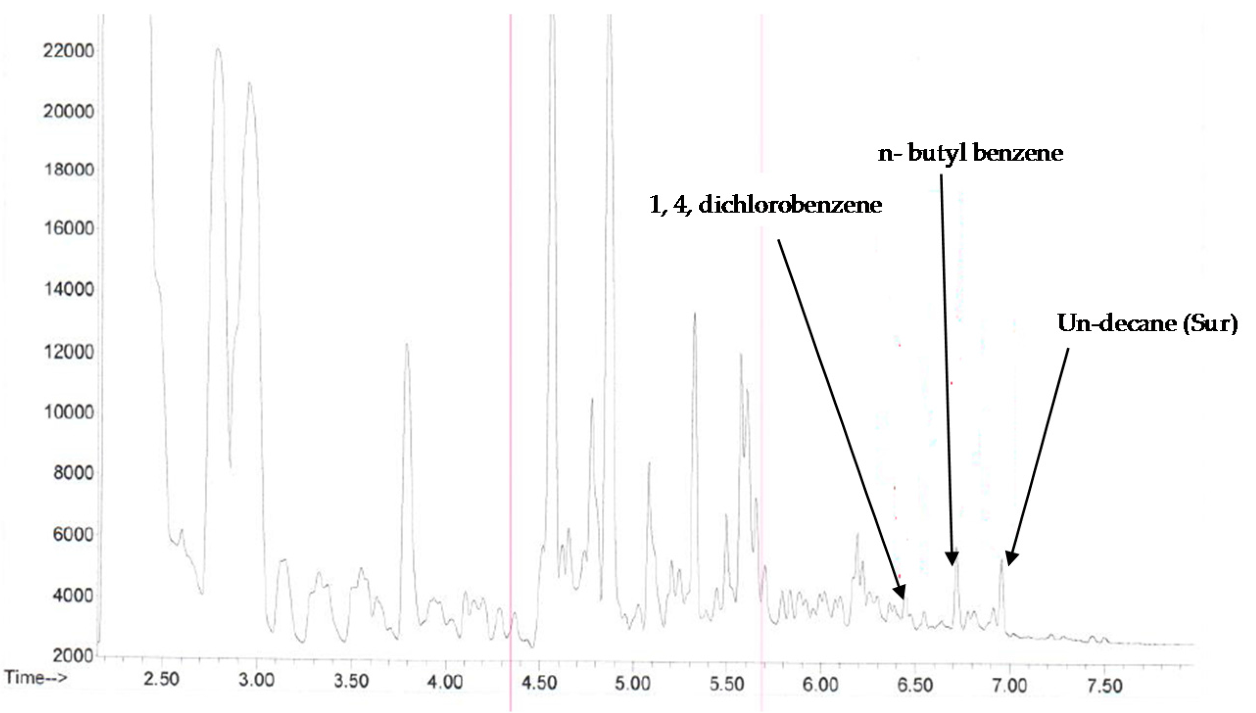
4.3. Headspace GC-FID Analysis

The oil sample is analyzed using a head space FID-GC with methanol solution. The oil sample shows the existence of the following hydrocarbon compounds:
  • 1,4-dichlorobenzene, C6H4Cl2
  • n-butyl benzene, C10H14
  • Un-decane, C11H24
The first chromatogram in Figure 14 was identified using headspace GC with an FID to determine the C6 to C10 hydrocarbon fraction.
The second chromatogram was analyzed using GC-FID with methanol solvent. The labeled retention times are for decane (C10), hexadecane (C16) and tetratriacontane (C34) as shown in Figure 15.
The quantitative analysis of the pyrolysis oil is shown in Table 3. The data displayed in μ g g shows 87.9 wt. % 1,4-dichlorobenzene, minor percentages of benzene, and ethylbenzene. In terms of hydrocarbon analysis it shows the highest concentration of 2340   μ g g for (C10–C16), followed by C16–C34 and small traces of heavier C34–C50 hydrocarbon content.

4.4. Product Yield Results

As mentioned in the Introduction, the product yield from LDPE pyrolysis at 550 °C is 93 wt. %. The lower hydrocarbon liquid yields can be due to higher operating temperatures which increases the formation of light hydrocarbon products such as methane and ethane. The final tar and wax sample are weighted and considered undesired product. Below (Table 4) are the results from a 15 g LDPE sample.

5. Discussion

The DC thermal plasma can achieve a thermal density of 0.129 MJ/m3 which satisfies the activation energy required for the pyrolysis of 15 g of LDPE. The DC thermal plasma also reaches the required operating temperature (i.e., above 625 °C) faster in comparison with other heating sources. The LDPE sample yielded 56.9 wt % fuel oil which consisted of 87.5 wt. % 1,4-dichlorobenzene, toluene, undecane and xylenes as well as C10 and, C16 fractions. The tar content was 5.2 wt. % and the gaseous emissions were tested for flammability, proving the hydrocarbon nature of the rest of the products formed. The chlorine ions contamination might be due to using potable water from condensation of hydrocarbon gaseous products which contains chlorine ions. The lower product yield of liquid hydrocarbons from LDPE pyrolysis can be due to the higher operating temperature of DC thermal plasma which favors formation of light gaseous hydrocarbons due to a higher rate of thermal cracking [40]. This process system is more favorable than other pyrolysis systems which rely on gas burners for pyrolysis reactions due to the absence of environmental emissions and higher temperature controllability of the DC thermal plasma. Overall, the DC thermal plasma shows the ability to be used for LDPE pyrolysis and can provide the needed thermal energy with a constant heating rate as required.

6. Conclusions

This work illustrates the integration of a DC controllable thermal plasma circuit to be used in thermoplastic to oil conversion reactions. While pyrolysis reactions consume a large amount of thermal energy (around 1047 KJ/Kg of LDPE), the thermal plasma can meet the thermal requirements without fuel emissions like gas burners. Also, the plasma temperature provides a constant heating rate of 7.8 °C/min which prevents tar formation and increases the stability of the resulting pyrolysis oils. In the experimental setup, a 270 W DC thermal plasma is used for a 15 g LDPE sample and pyrolysis oils were collected for a product yield of 56.9 wt. %. The pyrolysis oil sample shows butyl-benzene as a major product and the existence of small traces of decane diesel range oil. The DC thermal plasma system can be used to replace other heating sources in pyrolysis reactors.

Acknowledgments

Authors would like to thank Janak Handa—Chief Operating Officer, Pro-Flange Limited for their support to this research work.

Author Contributions

Hossam A. Gabbar and Mohamed Aboughaly conceived and designed the experiments; Mohamed Aboughaly and C.A. Barry Stoute performed the experiments; Hossam A. Gabbar and Mohamed Aboughaly analyzed the data and wrote the paper.

Conflicts of Interest

The authors declare no conflict of interest.

Abbreviations

DRODiesel range oil
GC-FIDGas chromatography-Flame ionization detector method
LDPELow density polyethylene

Nomenclature

CTTotal Capacitance (F)
EaActivation energy (KJ/mol)
kReaction constant (1/s)
koReactant constant at standard pressure and temperature
LLength of inductance (unit: Henry kg m2 s−2 A−2)
pFPico (10−12) Farad (s4 × A2 × m−2 × kg−1)
TpPlasma temperature (°C)
RIdeal gas constant (atm/mol·K)
woMass of initial LDPE sample (g)
wtMass of unreacted LDPE sample (g)
w Mass of reactant residue(g)
τ Reaction residence time(min)
dx dt Conversion rate with respect to time (g/s)
α conversion of reactants to liquid oil products (g)

References

  1. Lopez, A.; Marco, I.; Caballero, M.; Laresgioti, M.; Adrados, A. Pyrolysis of municpal plastic wastes: Influence of raw material composition. Waste Manag. 2010, 30, 620–627. [Google Scholar] [CrossRef] [PubMed]
  2. Syamsiro, M.; Saptoadi, H.; Norsujianto, T.; Noviasri, P.; Cheng, S.; Alimmudin, Z.; Yoshikawa, K. Fuel oil production from municipal plastic wastes in sequential pyrolysis and catalytic reforming reactors. Procedia Eng. 2014, 47, 180–188. [Google Scholar] [CrossRef]
  3. Shafferina, S.; Abnisa, F.; Daud, W.; Aroua, M. A review on pyrolysis of plastic wastes. Energy Convers. Manag. 2016, 115, 308–326. [Google Scholar]
  4. Achilias, D.S.; Roupakias, C.; Megalokonomos, P.; Lappas, A.A.; Antonakou, E.V. Chemical recycling of plastic wastes made from polyethylene (LDPE and HDPE) and polypropylene (PP). J. Hazard. Mater. 2007, 149, 536–542. [Google Scholar] [CrossRef] [PubMed]
  5. Balat, M.; Balat, M.; Kırtay, E.B. Main routes for the thermo-conversion of biomass into fuels and chemicals Part 1: Pyrolysis systems. Energy Convers. Manag. 2009, 50, 3147–3157. [Google Scholar] [CrossRef]
  6. Özge, Ç.; Pütün, A. Thermal and kinetic behaviors of biomass and plastic wastes in co-pyrolysis. Energy Convers. Manag. 2013, 75, 263–270. [Google Scholar]
  7. Almeida, D.; Marques, M. Thermal and catalytic pyrolysis of plastic waste. Polímeros 2016, 26, 44–51. [Google Scholar] [CrossRef]
  8. Zhang, X.; Lei, H.; Yadavalli, G.; Zhu, L.; Wei, Y.; Liu, Y. Gasoline-range hydrocarbons produced from microwave-induced pyrolysis of low-density polyethylene over ZSM-5. Fuel 2015, 144, 33–42. [Google Scholar] [CrossRef]
  9. Sharma, B.K.; Moser, B.R.; Vermillion, K.E.; Doll, K.M.; Rajagopalan, N. Characterization and fuel properties of alternative diesel fuel from pyrolysis of waste plastic grocery bags. Fuel Process. Technol. 2014, 122, 79–90. [Google Scholar] [CrossRef]
  10. Park, J.; Park, K.; Park, J.; Kim, D. Characteristics of LDPE pyrolysis. Korean J. Chem. Eng. 2002, 19, 658–662. [Google Scholar] [CrossRef]
  11. Panda, A.; Singh, R.; Mishra, D. Thermolysis of waste plastics to liquid fuel—A suitable method for plastic waste management and manufacture of value added products—A world prospective. Renew. Sustain. Energy Rev. 2010, 14, 233–248. [Google Scholar] [CrossRef]
  12. Derirbas, A. Pyrolysis of municipal plastic wastes for recovery of gasoline-range hydrocarbons. J. Anal. Appl. Pyrolysis 2004, 72, 1. [Google Scholar]
  13. Siddiqui, M.; Redwi, H. Pyrolysis of mixed plastics from the recovery of useful products. Fuel Process. Technol. 2009, 90, 4. [Google Scholar] [CrossRef]
  14. Aboulkas, A.; El Harfi, K.; El Bouadilli, A. Thermal degradation behaviors of polyethylene and polypropylene. Part I: Pyrolysis kinetics and mechanisms. Energy Convers. Manag. 2010, 51, 1363–1369. [Google Scholar] [CrossRef]
  15. Kayacan, I.; Dogan, O. Pyrolysis of low and high density polyethylene. Part I: Non-isothermal pyrolysis kinetics. Energy Source Part A Recovery Util. Environ. Eff. 2008, 30, 385–391. [Google Scholar] [CrossRef]
  16. Westerhout, R.W.J.; Waanders, J.; Kuipers, J.A.M.; van Swaaij, W.P.M. Kinetics of the low-temperature pyrolysis of polyethene, polypropene, and polystyrene modeling, experimental determination, and comparison with literature models and data. Ind. Eng. Chem. Res. 1997, 36, 1955–1964. [Google Scholar] [CrossRef]
  17. Wongkhorsub, C.; Chindaprasert, N. A comparison of the use of pyrolysis oils in diesel engine. Energy Power Eng. 2013, 5, 350–355. [Google Scholar] [CrossRef]
  18. Chiellini, E.; Solaro, R. Do biopolymers fulfill our expectations concerning environmental benefits. In Biodegradable Polymers and Plastics; Springer: Berlin, Germany, 2003; p. 89. [Google Scholar]
  19. Kalargaris, I.; Tian, G.; Gu, S. Combustion, performance and emission analysis of a DI diesel engine using plastic pyrolysis oil. Fuel Process. Technol. 2017, 157, 108–115. [Google Scholar] [CrossRef]
  20. Feng, G. Pyrolysis of Waste Plastics into Fuels. Ph.D. Thesis, University of Catenbury, Chrstchurch, New Zealand, 2010. [Google Scholar]
  21. Preston, J.; Rodroguez, F.; Gent, A.; Stevens, M.; Bierwagen, G.; Kauffman, G. Major Industrial Polymers, LDPE. Available online: https://www.britannica.com/science/polyethylene (accessed on 6 June 2017).
  22. Onwudili, J.; Insura, N.; Williams, P. Composition of products from the pyrolysis of polyethylene and polystyrene in a closed batch reactor: Effects of temperature and residence time. J. Anal. Appl. Pyrolysis 2009, 86, 293–303. [Google Scholar] [CrossRef]
  23. Tamosiunas, A.; Valatkevicius, P.; Valincius, V.; Grigaitiene, V. Production of synthesis gas from propane using thermal water vapor plasma. Int. J. Hydrogen Energy 2014, 39, 2078–2086. [Google Scholar] [CrossRef]
  24. Huang, H.; Tang, L. Treatment of organic waste using themal plasma pyrolysis technology. Energy Convers. Manag. 2007, 48, 1331–1337. [Google Scholar] [CrossRef]
  25. Kim, Y.; Ferreri, V.; Rosocha, L.; Anderson, G.; Abbatte, S.; Kim, K. Effect of plasma chemistry on activated propane/air flames. IEEE Trans. Plasma Sci. 2006, 34, 2532–2536. [Google Scholar] [CrossRef]
  26. Pyrolysis of Waste Plastics: Effect of Heating Rate on Product Yields and Oil Properties. Available online: https://www.scientific.net/AMR.666.1 (accessed on 6 June 2017).
  27. Rao, L.; Rivard, F.; Carabin, P. Thermal Plasma Torches for Metallurigal Applications. Available online: http://www.pyrogenesis.com/wp-content/uploads/2014/01/1.-TMS-2013-publications_Pyro-extract.pdf (accessed on 6 June 2017).
  28. Yu, Q.; Kong, M.; Liu, T.; Fei, J.; Zheng, X. Non-thermal plasma assisted CO2 reforming of propane over Ni/γ-Al2O3 catalyst. Catal. Commun. 2011, 12, 1318–1322. [Google Scholar] [CrossRef]
  29. Fabry, F.; Rehmet, C.; Rohani, V.V.; Fulcheri, L. Waste gasification by thermal plasma: A review. Waste Biomass Valor 2013, 4, 421–439. [Google Scholar] [CrossRef]
  30. Tamosiunas, A.; Valatlevicius, P.; Grigaitiene, V.; Valincius, V. A cleaner production of synthesis gas from glycerol using thermal water steam plasma. J. Clean. Prod. 2016, 130, 187–194. [Google Scholar] [CrossRef]
  31. Tang, L.; Huang, H.; Hao, H.; Zhao, K. Development of plasma pyrolysis/gasification systems for energy efficient and environmentally sound waste disposal. J. Electrost. 2013, 71, 839–847. [Google Scholar] [CrossRef]
  32. Wampler, T. Analytical pyrolysis: An overview. In Applied Pyrolysis Handbook, 2nd ed.; CRC Press: Boca Raton, FL, USA, 2007; pp. 1–4. [Google Scholar]
  33. Williams, P.; Slaney, E. Analysis of products from the pyrolysis and liquefaction of single plastics and waste plastic mixtures. Resour. Conserv. Recycl. 2007, 51, 4. [Google Scholar] [CrossRef]
  34. Williams, P.; Williams, E. Fluidized bed pyrolysis of low density polyethylene to produce petrochemical feedstock. J. Anal. Appl. Pyrolysis 1999, 51, 107–126. [Google Scholar] [CrossRef]
  35. Jamradloedluka, J.; Lertsatitthanakorn, C. Characterization and utilization of char derived from fast pyrolysis of plastic wastes. Procedia Eng. 2014, 69, 1437–1442. [Google Scholar] [CrossRef]
  36. Wong, S.; Ngadi, N.; Abdullah, T.I.I. Current state and future prospects of plastic waste as source of fuel: A review. Renew. Sustain. Energy Rev. 2015, 50, 1167–1180. [Google Scholar] [CrossRef]
  37. Bird, J. Electrical circuit theory and technology. In Capacitors and Capacitance, 4th ed.; Oxford University Press: New York, NY, USA, 1997; p. 65. [Google Scholar]
  38. Banmongkol, C.; Mori, T.; Mizutani, T.; Ishioka, M.; Ishino, I. Effects of oxidation on electrical conduction and breakdown of low-density polyethylene films with different densities. Jpn. J. Appl. Phys. 1998, 37, 872–877. [Google Scholar] [CrossRef]
  39. Solonenko, O. Thermal Plasma Torches and Technologies, Plasma Torches: Basic Studies and Design, Chem; Science Publishing Group: New York, NY, USA, 2003. [Google Scholar]
  40. Horvat, N.; Ng, F. Tertiary polymer recycling: Study of polyethylene thermolysis as a first step to synthetic diesel fuel. Fuel 1999, 78, 459–470. [Google Scholar] [CrossRef]
Figure 1. Molecular structure of a LDPE repetitive unit [21].
Energies 10 00784 g001
Figure 2. Expected end-products from pyrolysis [22].
Energies 10 00784 g002
Figure 3. DC non-transferred thermal plasma [31].
Energies 10 00784 g003
Figure 4. LDPE degradation mechanism [32].
Energies 10 00784 g004
Figure 5. Experimental setup.
Energies 10 00784 g005
Figure 6. DC thermal plasma circuit.
Energies 10 00784 g006
Figure 7. Half wave rectifier simulation.
Energies 10 00784 g007
Figure 8. DC thermal plasma emissions at vacuum pressure.
Energies 10 00784 g008
Figure 9. DC generation over a ceramic nozzle.
Energies 10 00784 g009
Figure 10. DC thermal plasma on a 15 g LDPE.
Energies 10 00784 g010
Figure 11. Releasing hydrocarbon gaseous products through the condensation system.
Energies 10 00784 g011
Figure 12. Temperature profile of DC thermal plasma.
Energies 10 00784 g012
Figure 13. 7 mL of oil sample from 15 g LDPE.
Energies 10 00784 g013
Figure 14. FID-GC from 15 g of LDPE.
Energies 10 00784 g014
Figure 15. C10, C16 and C34 GC-FID.
Energies 10 00784 g015
Table 1. Effect of reaction temperature on LDPE pyrolysis [18].
Reaction Temperature (°C)Residence Time (min), τ
440132
45090
46095
47061
50040
Table 2. Plasma classifications [23].
Classification of PlasmaTp (K) Applications
High temperature Plasma (Equilibrium Plasma)106–108 Laser fusion plasma
Low temperature Plasma (Quasi-equilibrium Plasma)2 × 10³–3 × 10⁴Arc plasma, atmospheric RF discharge
Non-thermal Plasma (non-equilibrium Plasma)300–400Corona discharge
Table 3. Quantitative analysis of pyrolysis oil using a gas chromatography (GC).
CompoundResultUnits
1,4-Dichlorobenzene 87.9wt.%
Benzene0.008µg/g
Ethylbenzene0.041µg/g
F1 (C6–C10)-Less BTEX61.8µg/g
F1 (C6–C10) Including BTEX62.4µg/g
p-Xylene0.098µg/g
o-Xylene0.183µg/g
Toluene0.271µg/g
Total Xylenes0.281µg/g
Undecane134µg/g
Fraction (C10–C16)2340µg/g
Fraction (C16–C34)685µg/g
Fraction (C34–C50)<10µg/g
Table 4. Quantitative analysis and mass conversion of the thermoplastic sample.
Experimental ResultsLDPE Reactant (wo)15 g
Pyrolysis oil volume (density 1.22 g/cm3)7 mL (8.54 g)
Hydrocarbon gases5.68 g
Tar content0.78 g
α = 0.569 (56.9 wt %)

