1. Introduction
In previous decades, the power output from slow-speed diesel engines has increased steadily to meet higher propulsion power demands [
1,
2,
3]. This has resulted in more power from the same bore size and number of cylinders of an engine family. On 1st September 2006, the world’s largest containership EMMA MAERSK with a capacity of 11,000 TEU entered into service propelled by a Wärtsilä 14RT-Flex96C engine. With a power output of 5720 kW per cylinder, the 14 cylinder engine develops a continuous service output of 80,080 kW at 102 rpm, making it one of the world’s most powerful diesel engines. Other key drivers for engine development are low specific fuel oil consumption, which influences the direct operating costs of a ship, and environmental legislation limiting the level of harmful pollutants from diesel engines. Rising fuel prices over the past couple of years and enforcement of the legislation limiting the NO
x and SO
x from marine diesel engines has made these drivers more important.
An increase in power output from the cylinder results in an increase in fuel consumption. A reduction in the fuel consumption can be achieved by running the cylinder hotter, operating closer to stoichiometric conditions where cycle temperatures are higher, and increasing the volume expansion ratio to get greater work output for a fixed heat input. This is achieved at the engine optimisation point with near uniform air-to-fuel ratio across the combustion chamber but at the expense of a smaller safety margin between normal operation and thermal overload for continuous service rating. This has resulted in a reduction in design margins for the engines with higher component temperatures. When design threshold values are exceeded, such as the surface temperature of the combustion chamber, the engine is then operating in a so-called “thermal overload” condition.
To date, there has been research into finding solutions to thermal overload in the cylinder head of a heavy duty 6-cylinder diesel engine, in which thermal cracks were found in the valve bridge [
4]. As a potential solution to the previously stated problem, encasing the cylinder head in a water jacket was investigated to reduce the thermal stress of the diesel engine’s cylinder head [
4]. Thermal shock loading was reported to play a role in engine thermal stress along with steady-state temperature gradients and high combustion temperature [
5]. In order to protect the structural integrity of engines from corrosion, erosion and wear, thermal barrier coating technologies have been proposed and investigated [
5,
6,
7,
8,
9,
10]. However, very little evidence has been published which considers the probable causes of thermal overload of the engine. As the component temperatures are dependent on the flame size within the combustion chamber, its relationship to the air-fuel ratio was previously investigated using a flame visualisation test rig [
11]. The hypothesis indicated that the thermal overload was influenced by high surface temperatures due to contact with a voluminous flame, which itself was a likely consequence of a low air-to-fuel ratio [
11]. One possible reason for this phenomenon is that there is a deficiency of active radicals present in the combustion zone, which will slow down the flame propagation rate, thus contributing to make it more voluminous. This voluminous flame comes into contact with the combustion chamber components, breaking down the boundary layer and increasing the rate of heat transfer. This does not occur under lean burning conditions, where the flame is more compact and a cushion of air exists between the flame and the component surface [
11].
Some of the components that impact on the control of the air-to-fuel ratio are as follows: turbochargers, piston rings, cylinder liners, inlet and exhaust valves, scavenge valves and fuel injection systems. To identify the mechanisms that contribute towards a lower excess air-fuel ratio, an understanding of the gas exchange process is required. This insight will also allow the possibility of operating individual cylinders in multi-cylinder engines, under thermal overload conditions.
2. Fundamental Analysis
2.1. Gas Exchange Process of a Diesel Engine
The gas exchange process in a diesel engine is a phase during which the products of combustion from a cylinder are removed and replaced with a fresh charge for the subsequent combustion cycle. For a four-stroke engine, this process takes place in two dedicated strokes, while in a two-stroke engine, this process takes place within a few degrees around bottom dead center (BDC) [
12]. The air lost during this process is insignificant, neither is the difference between trapped and overall relative air-to-fuel ratio. Global air-to-fuel ratios for medium-speed four-stroke engines will be within the range of 1.8 to 2.2 [
13]. However, for two-stroke engines the air lost during the scavenge process, which is 30% to 40% of the total air supplied by the turbocharger, does not take part in the combustion process. As a result, two different excess air ratios are introduced, the overall air-to-fuel ratio and the trapped air-to-fuel ratio. Typical minimum design values for the overall and in-cylinder excess air ratios are 2.8 and 1.8 respectively, with one part of air being lost during the scavenging process.
The main components involved in the gas exchange process are the piston, piston rings, intake valve, exhaust valve and turbocharger(s) [
13]. Each component has an important role in the process; therefore, it is necessary to briefly discuss the function of each one in relation to the gas exchange process and how its operation will affect the overall and in-cylinder air-fuel ratios. Air leakage during the compression phase as a result of malfunctioning intake or exhaust valve can reduce the air-to-fuel ratio within the cylinder. A similar effect will be observed if the closure of either the exhaust valve in a two-stroke engine or the intake valve for a four-stroke engine are delayed. Leakage of air past the piston rings will also decrease the air-to-fuel ratio [
14]. A loss in turbocharger performance will result in less air being supplied to the engine for scavenging and combustion, thereby decreasing the air-to-fuel ratio.
Due to the limitation of conventional engine test benches, the influence of the leakage through the valves and the piston rings on the engine thermal load are unable to be measured routinely. Meanwhile, the ambient conditions will affect the intake mass flow rate and the exhaust mass flow rate, thus the corresponding air-to-fuel ratio. As a result, the influence of the ambient conditions on the engine thermal load will also be investigated. In the following sections, the influence of the ambient conditions, the turbocharger performance and the valve timing on the engine thermal overload will be presented.
2.2. Test Engine Selection
Engines were selected on the basis of the type of experiments to be performed. A decision was made to search for engine(s) operating in industry that have suffered from failures of the combustion chamber components due to thermal overload. The specifications of test engines selected for experiments are listed in
Table 1. Before installation of the thermal overload monitoring system, it was necessary to establish if the piston crown burn away was caused from hot corrosion due to high surface temperature. An inspection and measurement of the piston crowns in service, as well as spares, was carried out to establish that the most probable cause was high surface temperature due to a combustion flame contact as a result of a voluminous flame.
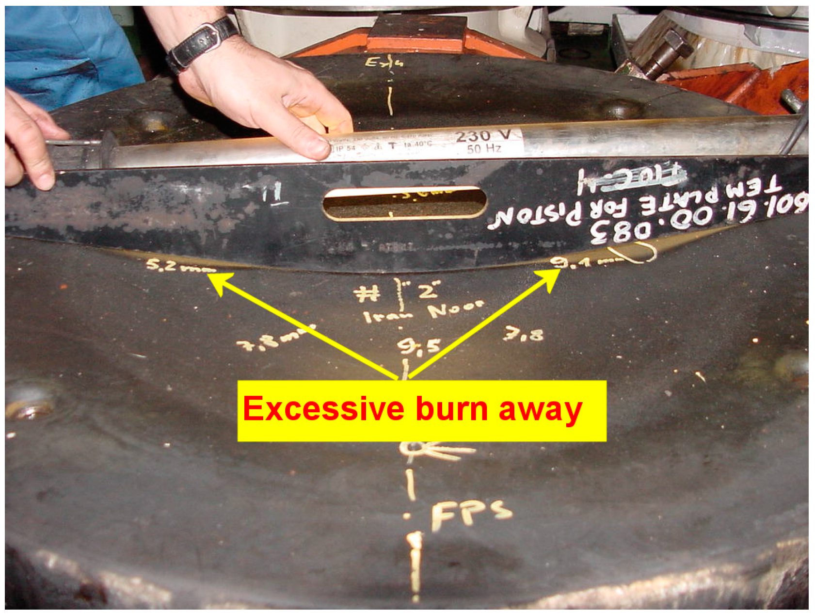
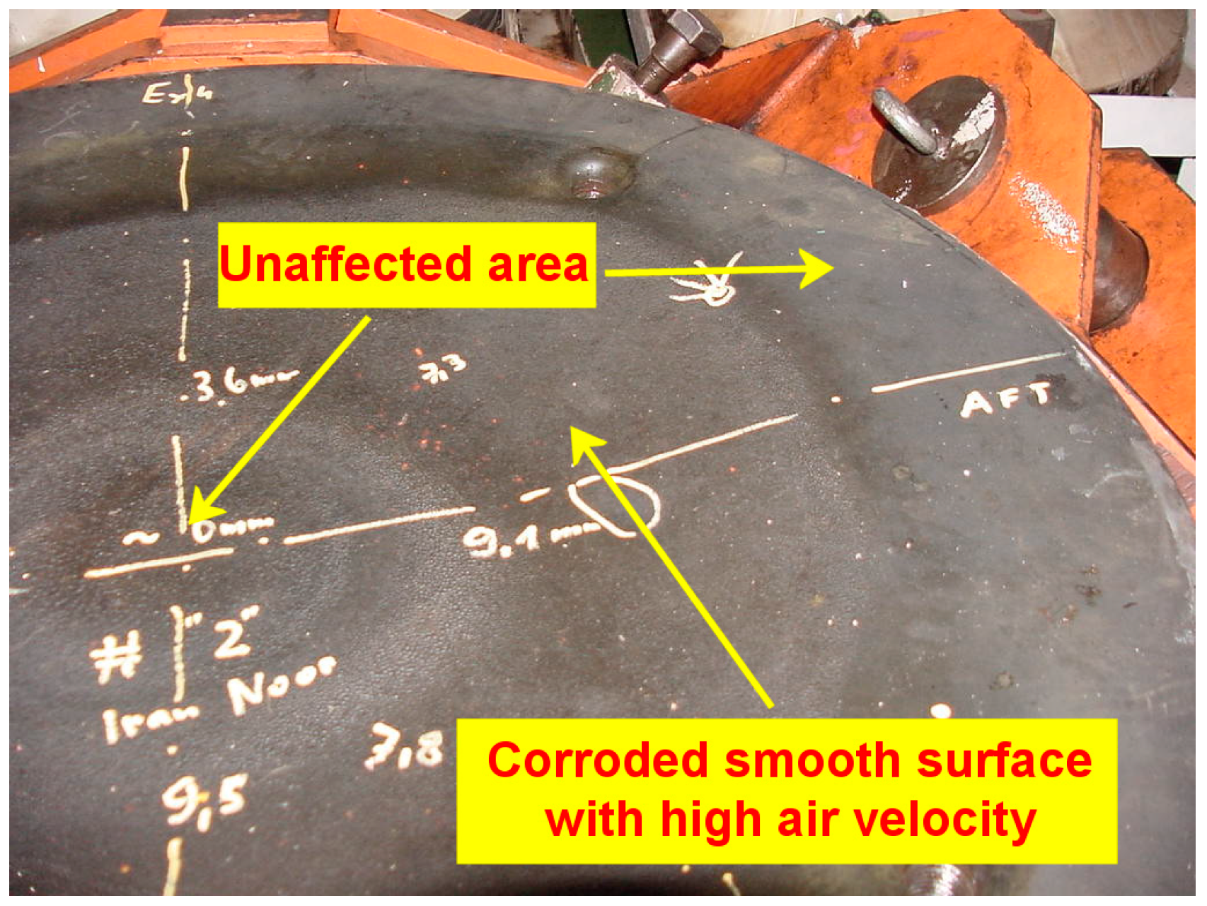
Inspection of a piston crown from the test engine, removed from service due to excessive burn away, showed signs of hot corrosion in the direction of fuel spray and air swirl. The corroded region had a “banana-shaped” outline which is similar to the pattern in which fuel is dispersed within the cylinder and was in excess of 9 mm in certain regions (
Figure 1). This represents a wear rate of 2 mm per 1000 h as opposed to a normal operational wear rate of 0.3 mm per 1000 h. Hot corrosion could have been caused by high crown surface temperature coupled with corrosive salt deposits, which melt and accelerate inter-granular corrosion. Under such conditions, it could be expected that the corroded area will appear with a rough surface and corroded boundaries (elephant skin) unless high localized air velocity produces a smooth surface. Such smooth areas were found in the area covered by the fuel spray (
Figure 2). Areas outside the heavily corroded region, towards the center and periphery of the crown, did not suffer from corrosive attack possibly due to two reasons; low surface temperature and no salt deposition. High surface temperature and salt deposition on the crown in the heavily burned-away regions could have been caused by flame and fuel impingement, respectively, resulting from a low air density within the cylinder. A reduction in the mass of air supplied for a fixed fuel charge reduces the rate of combustion, making the flame more voluminous, which would then come into contact with the piston crown. In an ideal scenario, the flame should be compact and should not come into contact with the piston crown or exhaust valve.
2.3. Engine Thermal Overload Monitoring System
The designed thermal overload monitoring system for a diesel engine mainly consists of a set of two sensors, a lambda sensor to measure the oxygen concentration and a fast response thermocouple to measure the temperature of the gas leaving the cylinder. From the test results, it is expected to achieve an indication of the engine thermal load and the quality of combustion. Currently available temperature and lambda sensors are mechanically robust and reliable for continuous monitoring (in a harsh environment), with the necessary signal conditioning system [
15,
16]. Other sensors, such as a crank angle sensor, are adopted to analyse the performance of the engine during operation. More importantly, the monitoring technology for engine diagnostics and condition-based maintenance needs to be developed in line with the present-day diesel engine technology, as it still largely relies on monitoring the in-cylinder pressure to identify faults [
17].
The data acquisition system comprised a laptop with a 16 channel analogue input multifunction National Instrument 6024E DAQ card (National Instruments Corporation, Austin, TX, USA) and a terminal box. Matlab code was developed to acquire data from the sensors with signal values within the range of −10 to +10 volts. A standard data acquisition system Doctor DK 2 from Icon Research was modified to provide a dual input channel system: one for the pressure measurements and the other for receiving signals from an oxygen sensor, fast response thermocouple and a proximity sensor. The proximity sensor was mounted on the exhaust valve for precise measurement of valve opening and closing times. A signal conditioning box was designed and built to act as an interface between the sensors and the Icon Research data acquisition system. Signals from the sensors, including the digital pickups on the flywheel for timing measurements, were conditioned prior to input. The measurements were taken from top dead centre (TDC) and the readings were averaged over a period of 20 cycles.
3. Ambient Conditions
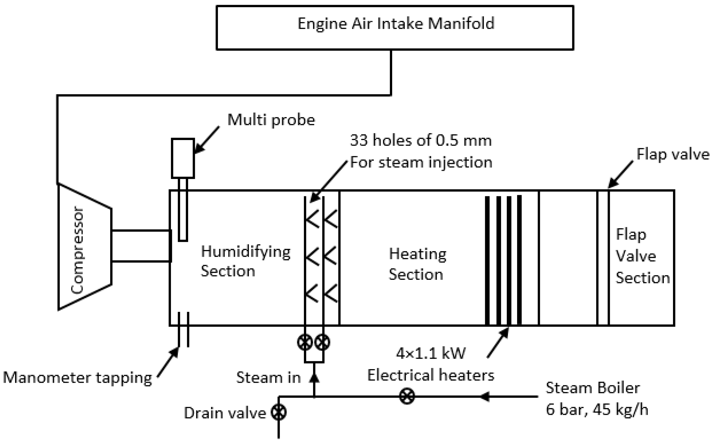
The aim of the experiment conducted on the Caterpillar engine was to identify the effect of different ambient conditions on thermal loading. It was difficult to conduct such an experiment on a slow-speed diesel engine; however, it was feasible to conduct the experiment in a laboratory environment on a high-speed Caterpillar 3116 engine with a lower air consumption rate. A simulation of the ambient conditions was achieved through installing a humidifying/heating air conditioning unit mounted upstream of the turbocharger. To simulate the actual ambient conditions at different geographical locations, an air conditioning unit was developed that was capable of changing the temperature and humidity of the air, while maintaining constant pressure at the inlet of the turbocharger. The conditioning unit was comprised of three different sections: the flap valve, heating and humidifying section.
Figure 3 shows a schematic representation of the air conditioning unit.
The flap valve section was 150 mm long and had a butterfly valve located midway along its length. This section was designed to maintain constant pressure at the inlet to the turbocharger compressor. Therefore, it was possible to compensate for any pressure rise during the heating and humidification processes. The heating section consisted of four 1.1 kW electrical heaters, individually housed in a 150 mm diameter and 250 mm long aluminium tube. It was designed to raise the temperature of the incoming air by 25 °C, with the engine running at full load. The humidifying unit had two steam pipes located across the diameter and angled at 90 degrees to each other, with a total of 33 injection holes 0.5 mm in diameter. Steam was injected via these holes to raise the humidity of the incoming air and provided adequate time for the mixture to become homogeneous before reaching the turbocharger. A multi-probe fitted at the end of the tube measured the air temperature and the relative humidity at inlet to the turbocharger. A 6 bar, 45 kg/h capacity steam boiler supplied the saturated steam for the system. The degree of humidification was achieved by throttling the main steam stop valve before the humidifying unit.
Ambient conditions, representing the different climates of Singapore, Miami, Newcastle and Abu Dhabi were simulated using the air conditioning unit and these test conditions are presented in
Table 2. Since the engine tests were emulating in-service ambient conditions, in accordance with ISO 8178 requirements, the field tests atmospheric factor (
) was applied to design the experiment with a value between 0.93 and 1.07. The atmospheric factor is determined according to the following formula for turbocharged compression ignition engines with or without intercooling:
where
is the dry atmospheric pressure (kPa);
is the absolute temperature of the intake air (K).
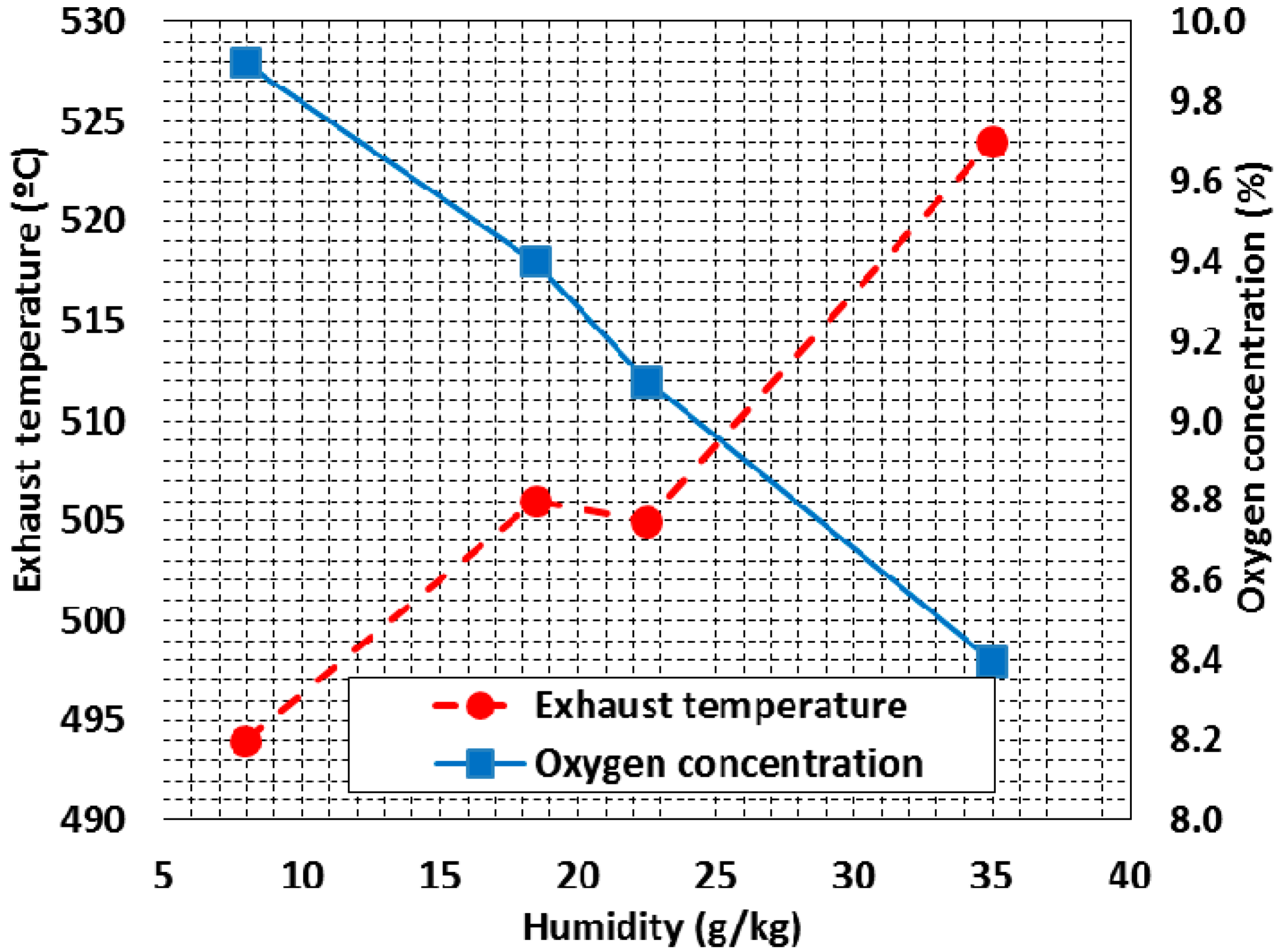
Measurements made during the tests at constant load and scavenging air temperature show a strong correlation between humidity levels and percentage oxygen content present in the engine exhaust for near-constant ambient air temperature (
Figure 4). Higher humidity levels resulted in lower oxygen concentrations in the exhaust gas, which indicates a lower trapped air-to-fuel ratio. The exhaust gas temperature increased by 30 degrees from low- to high-humidity conditions (
Table 2). This increase in exhaust gas temperature is also indicative of a lower trapped air-to-fuel ratio. When the engine was operating under sub-tropical and tropical conditions, a significant drop in oxygen concentration in the engine exhaust was observed.
4. Turbocharger Performance
Tests were undertaken on a Sulzer RTA 96C engine; the engine was experiencing surging of its turbocharger under part loading conditions (approximately 65% load and below). To investigate the effect of surging on combustion and engine performance, four of the twelve cylinders (5, 6, 7 and 8) were instrumented and pressure tapping was fitted on all three turbochargers to monitor their performance. The performance testing was carried out at 53% and 65% load, which corresponds to 77 and 83 RPM, respectively. Measurements from the four instrumented cylinders and all of the turbochargers were taken when the load was relatively stable during operating conditions and temperatures and pressures had stabilized.
During performance testing, the turbochargers were surging at 53% and 65% load, indicating that the compressors were operating close to the surge line. The surging was more pronounced from turbochargers 1 and 2; this condition did not occur at higher loads. White smoke was observed from the engine exhaust stack at lower loads, indicating the presence of unburnt fuel, potentially due to non-stoichiometric combustion. The air pressure surrounding the turbochargers at lower loads was approximately 50 mmWC and therefore the possibility of surging due to air starvation of the turbochargers could be ruled out. As the engines are designed for overall and trapped lambda values of 3.2 and 2.0, respectively, it was envisaged that the possibility of obtaining white smoke from the stack was due to rich combustion as a result of insufficient air availability due to performance of the turbochargers, inefficient scavenging or poor combustion due to a cold chamber. The latter is also possible under part-load operations where the combustion chamber is too large and the flame is quenched due to a relatively cold combustion chamber.
Performance calculations indicate that the turbochargers were operating close to the surge line with a surge margin less than 5% on two of the turbochargers. Mass flow calculations through the turbine sides of the turbochargers show that the overall lambda values at 53% and 65% loads were approximately 2.8, which are lower than the standard design value of 3.2. The corresponding values of 75% and 85% load were 2.9 and 3, respectively, which is also less than the standard design value. A simple calculation is made for a steady-flow constant-pressure combustion chamber operating on gas oil. Stoichiometric air demand for the fuel is 14.9 kg and if combustion is assumed to be complete, the products will be CO
2, H
2O and N
2. The general combustion equation, where
λ is the excess air ratio is given by:
The oxygen concentration in the exhaust gas,
can be represented by:
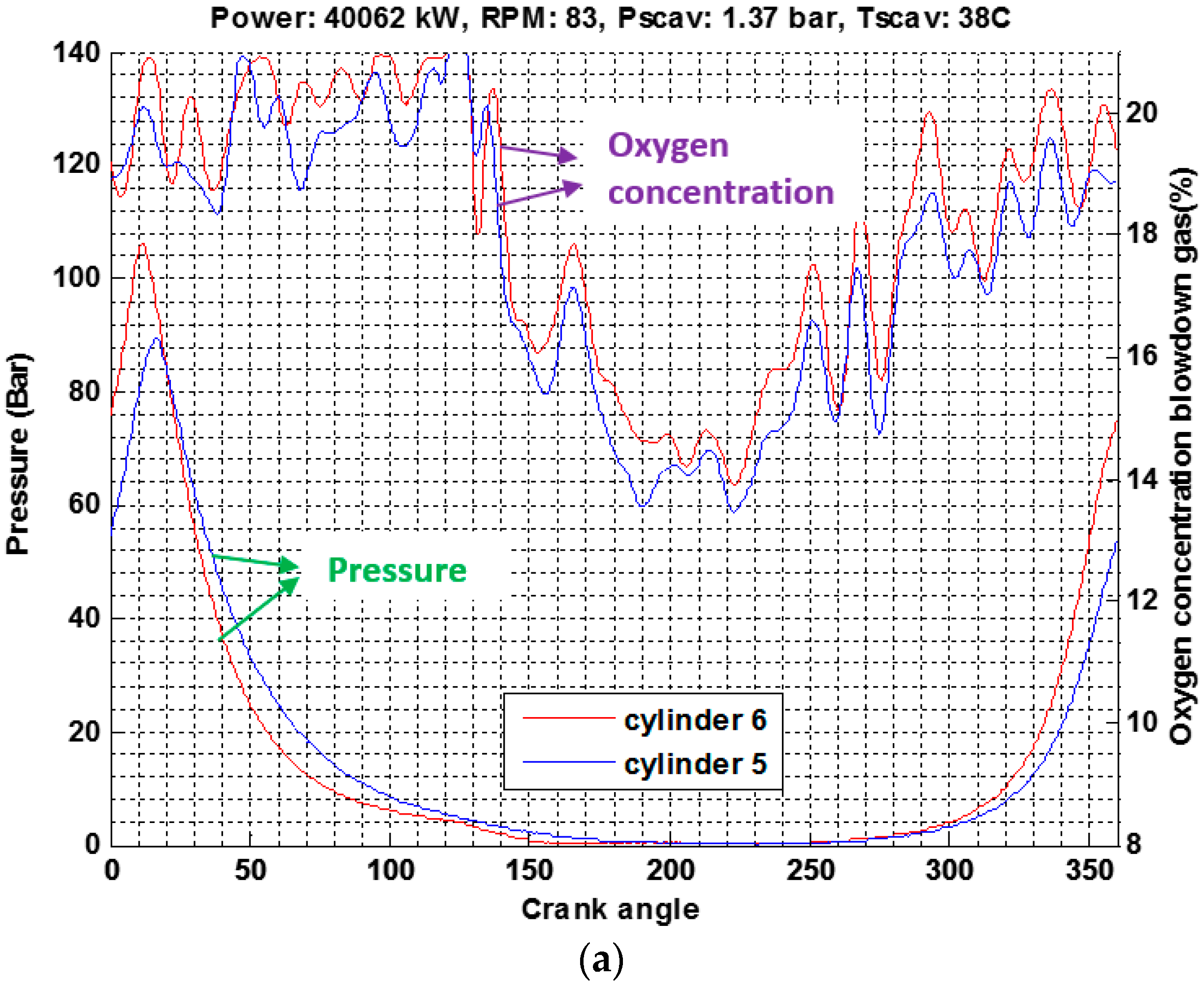
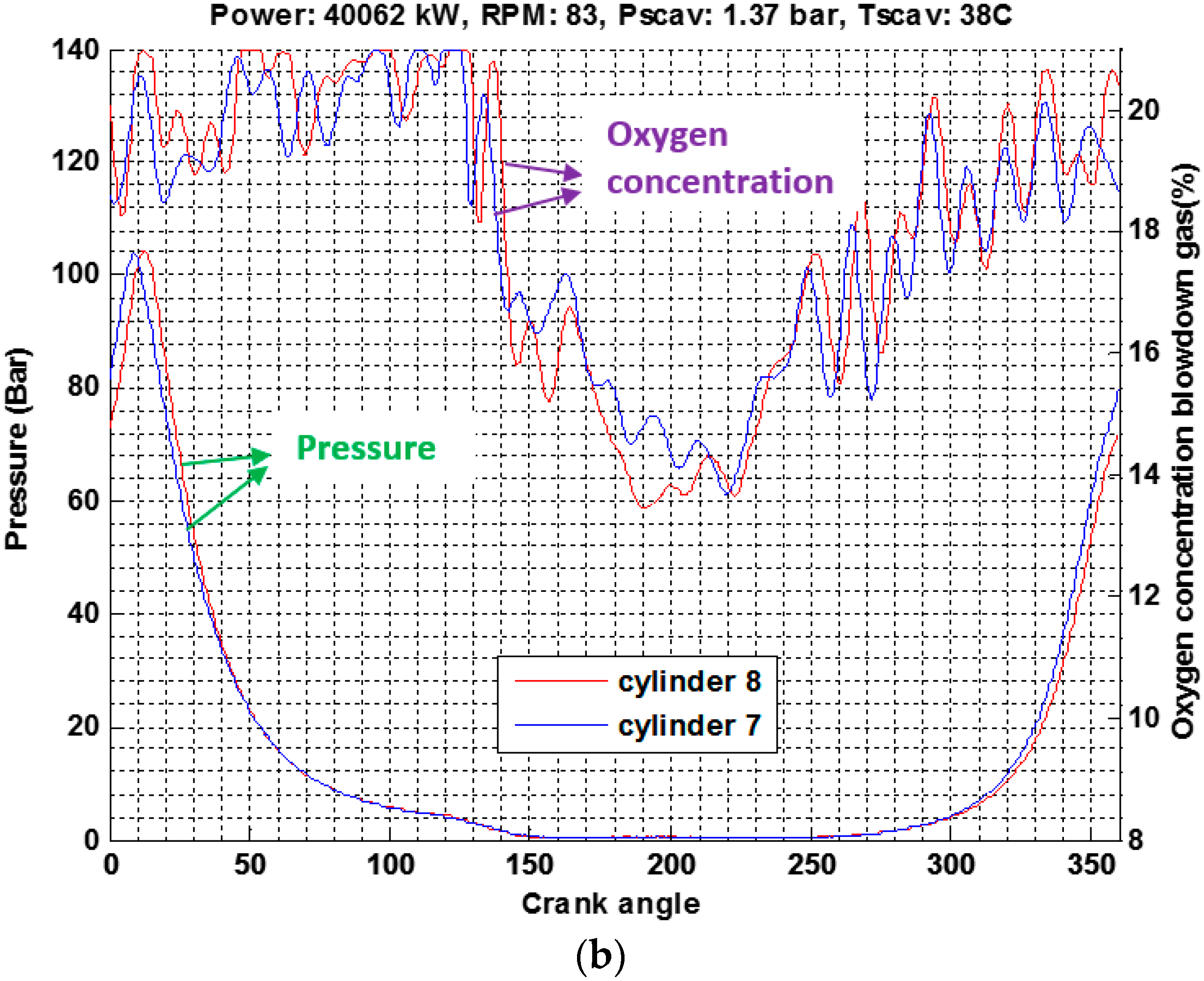
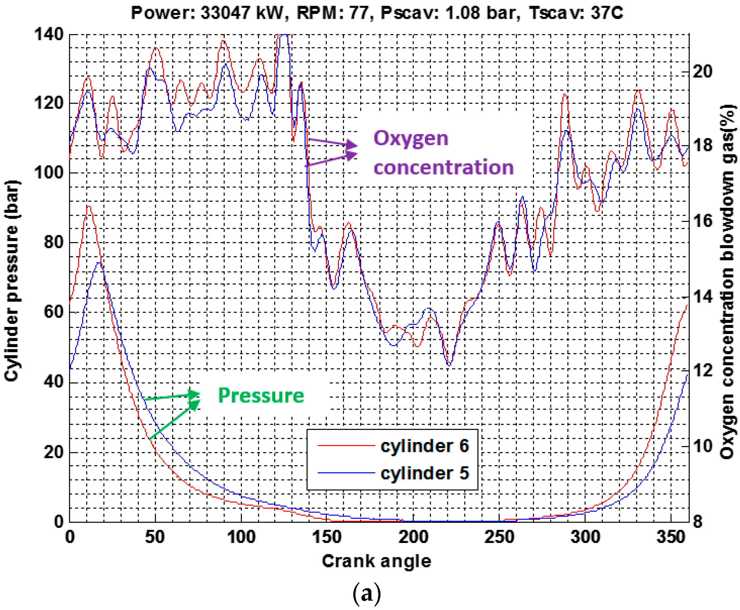
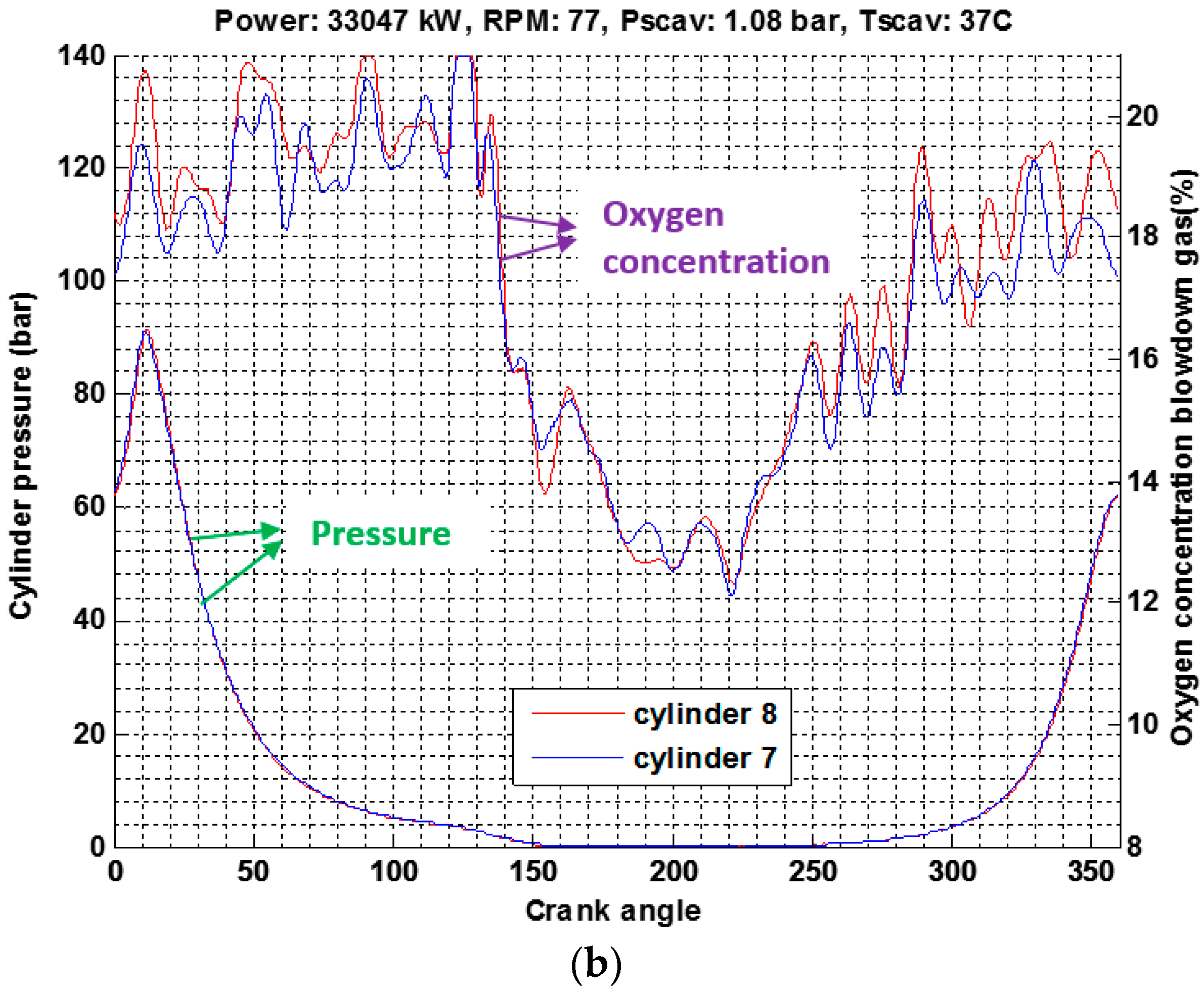
The effect of the lower overall air-fuel ratio on combustion can be observed from the oxygen concentration in the blowdown gas from the cylinder. From theoretical calculations above, it is expected that the oxygen concentration in the blowdown gas would be approximately 10% to 11.5% for a trapped lambda value of 2. However, a higher oxygen concentration of 12% and 13.5% in the blowdown gas at 53% and 65% load, respectively, is an indication of incomplete combustion (
Figure 5 and
Figure 6). The variation in oxygen concentration over smaller crank angles is a direct consequence of the pressure wave travelling in the exhaust manifold. This was confirmed while taking pressure measurements upstream of the turbines on the turbochargers. The contamination of air trapped in the cylinder can be estimated from the percentage of oxygen present in the gas leaving the cylinder at the instant the exhaust valve closes. With the average exhaust valve closing angle of 249 and 252 at 53% and 65%, respectively, the corresponding average oxygen concentrations are 16% and 17.5%. It was expected that the oxygen concentration of exhaust gas leaving the cylinder at the instant the valve closed should be at minimum 18.5% or 19%. The compression pressure for cylinder 5 is low and this had a consequential effect on the peak pressure.
The tests show that a contaminated air charge in the cylinder, which reduces the trapped air-to-fuel ratio, results in partial combustion and is indicated by a high oxygen concentration in the blowdown gas. This partial combustion is indicated by a white smoke at part-load with a relatively cold combustion chamber, as part of the fuel is unburnt, and black-brownish smoke at higher loads with a hotter combustion chamber.
5. Valve Timing
5.1. Late Closure of Exhaust Valve
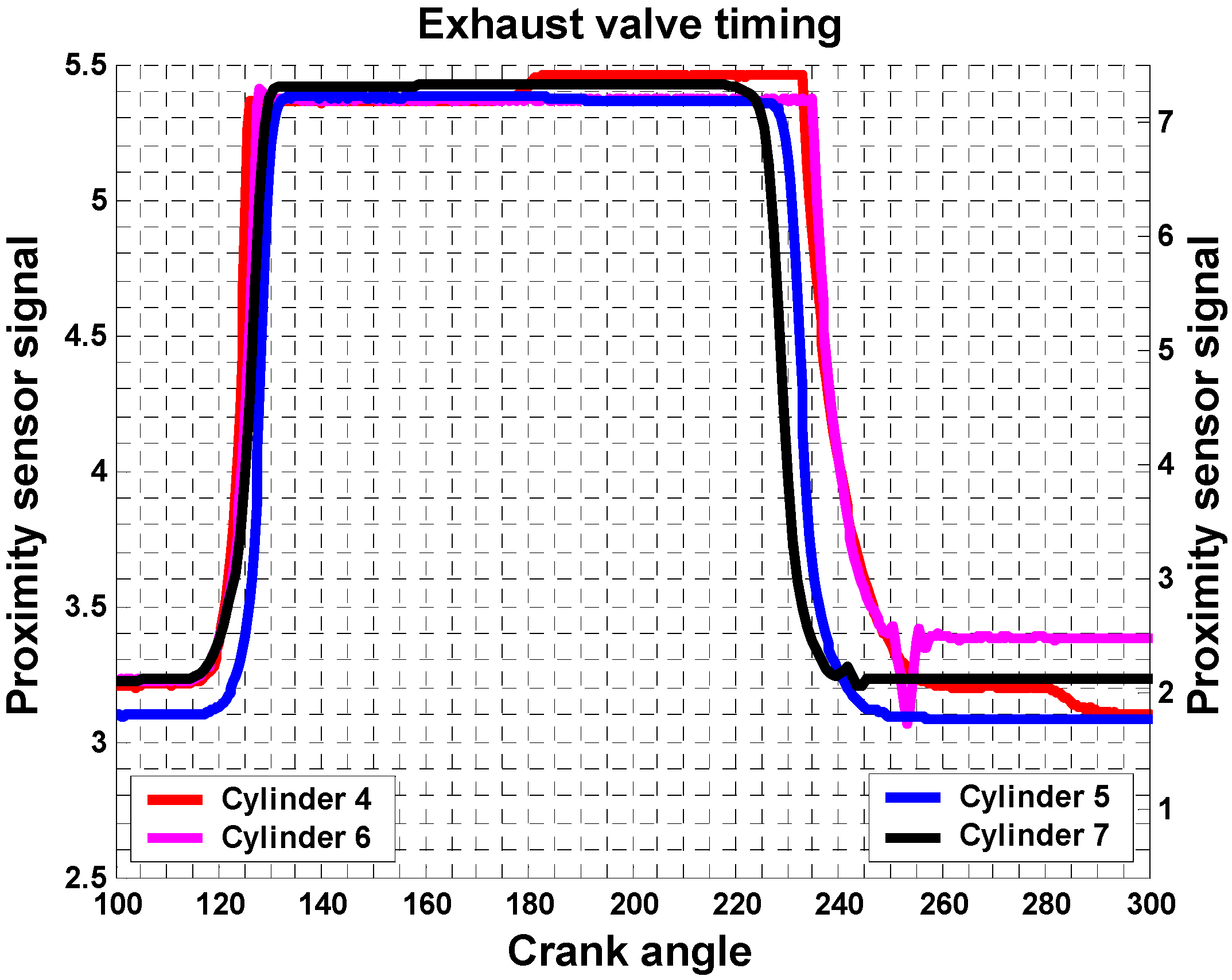
The tests were carried out on four cylinders of a Sulzer 7RTA84T engine having high piston crown burn rates with the lambda and proximity sensors fitted. During the tests, the power developed by the engine was 80% of its maximum continuous rating (27,160 kW). As scavenging air flow through each cylinder is different, the oxygen concentration values required to predict the trapped lambda are taken as the minimum value observed during the process. The data presented in
Figure 7 and
Figure 8 show the correlation between oxygen concentration and exhaust valve timing for individual cylinders. As expected, the cylinder with the latest exhaust valve closing time has the lowest oxygen concentration in the blowdown gas, indicating loss of air and vice-versa. An oxygen concentration of less than 8% would result in a voluminous flame with the size increasing for lower oxygen concentrations.
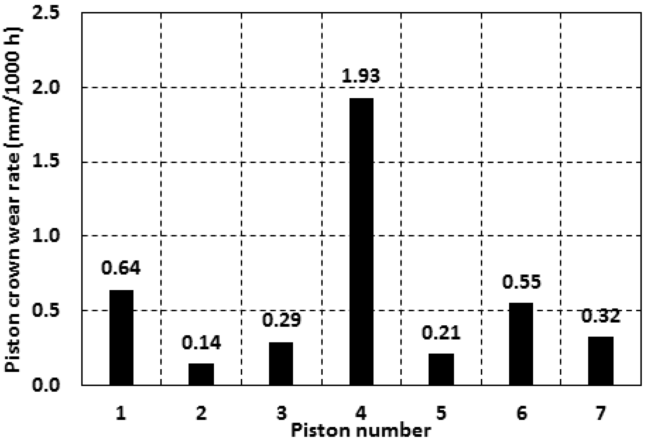
Piston crown wear rate measurements from the test engine are shown in
Figure 9. The minimum concentration of oxygen can be correlated, in this particular case, to the piston crown burn rate due to the high rate of heat transfer from a voluminous flame. Referring to
Figure 9, cylinder 4 has the lowest oxygen concentration in the blowdown exhaust gas and the highest relative piston crown wear rate. Cylinder 5 has the highest oxygen in the blowdown exhaust gas and the lowest piston crown wear rate. Cylinders 6 and 7 have oxygen concentrations between cylinders 4 and 5 and their piston crown burn rate are consistent. Therefore, the system indicates that if the oxygen concentration in the blowdown gas increases, then the piston crown wear rate will decrease oxygen levels. Exhaust valve timing measurements indicated that the cylinder with the highest wear rate had its valve closure 10 degrees later than the cylinder with lowest wear rate. The loss of air from cylinder resulted in a reduction in the trapped lambda value which contributed to a voluminous flame, resulting in a high piston crown surface temperature and an accelerated hot corrosion event.
5.2. Early Closure of Exhaust Valve
To investigate the effect of air contamination in the cylinder with residual gases from the previous cycle, tests were conducted on a Sulzer 7RTA84T-D engine with higher-than-average exhaust temperature at part-load. The closing time of the exhaust valve for cylinders 1, 3 and 4 are within 40 to 44 degrees after BDC and are approximately 15 to 19 degrees earlier than the designed 59 degrees for this load condition. The early closure of the exhaust valve was caused by a malfunction of the throttle valve mechanism, which controlled the leakage rate of the lubricating oil from the hydraulic push rod. Cylinder 1 was selected as the reference cylinder as it did not show signs of scuffing, while cylinders 3 and 4 had experienced scuffing, indicating potential thermal overload conditions.
The data in
Figure 10 show the oxygen concentration and transient temperature signature of exhaust gas leaving cylinders 1, 3 and 4 with the engine operating at 52% load (58 RPM). It was observed that cylinder 4 had the lowest oxygen concentration at 7.3%, followed by cylinder 3 with a value of 7.9% and finally cylinder 1 had the highest oxygen concentration of 8.3%. It was also found that the exhaust temperatures from cylinders 4 and 3 were approximately 45 °C and 25 °C higher than cylinder 1, respectively. Overall, the thermal load is close to the limit for all of the cylinders (since cylinder 1 is close to 8%) due to insufficient air being available at this load, resulting from poor turbocharger performance. It is expected that the engine will not be operating for prolonged periods at this load; therefore, the effect on overall performance should be limited. However, malfunctioning of the running gear (which is responsible for the scavenging process) would result in less air being trapped for combustion.
The data presented in
Figure 11 show the Oxygen concentration signature with respect to exhaust valve timing. Measurements showed that the exhaust valves were closing earlier than the designed condition, which impaired the scavenging process and increased the level of residual gas trapped in the cylinder. This resulted in a reduction in the actual air-to-fuel ratio and high exhaust gas temperatures. This problem can be observed by examining the oxygen concentration of the gas leaving the cylinder at the instant the exhaust valve closes, which is 14% for cylinders 1 and 3, and 12.5% for cylinder 4 (
Figure 11). The optimum would be between 18% to 19% oxygen in the gas leaving the cylinder when the exhaust valve closes. The higher the contamination of the air charge in the cylinder results in a lower actual air-to-fuel ratio, which reduces the oxygen concentration in the blowdown gas.
There is an optimum range for which the exhaust valve is required to close in order to achieve the desired trapped air-to-fuel ratio within the cylinder; if the valve is closed early, the trapped air-to-fuel ratio will reduce due to contamination with residual gases. A similar effect will be observed when the valve is closed later due to loss of air from the cylinder. The data in
Figure 12 show the cylinder pressure and exhaust valve timing against engine crank angle. At the instant the exhaust valve opens, the pressure in the cylinder is higher than the manifold pressure, resulting in a fraction of the residual gas leaving the cylinder due to a pressure differential (blowdown). As the scavenge air ports open (approximately 143° CA after TDC), the pressure in the cylinder is lower than the under-piston scavenge space, as the scavenging process starts the pressure in the cylinder increases. A slight drop in cylinder pressure is observed (approximately 216° after TDC) when the inlet ports close while the exhaust valve is still open.
6. Summary and Conclusions
In this paper, the influence of the gas exchange process on the engine thermal overload was discussed. The hypothesis has indicated that the engine thermal overload was potentially caused by a low air-fuel ratio. Thus, the ambient conditions, the turbocharger performance and the valve timing, which are responsible for maintaining the required air-fuel ratio, were investigated. Experimental results and conclusions for each of the potential parameters mentioned above are summarized as following:
- (1)
To simulate the ambient conditions at different geographical locations, experiments were conducted on a high-speed diesel engine with a humidifying and temperature control test piece mounted upstream of the turbocharger. Experiment results showed that the oxygen concentration decreased from 9.9% to 8.4% with the specific humidity in air increasing from 7.8 g/kg to 33 g/kg, indicating an increase in thermal load, which can be attributed to the reduction in dry air available for combustion. The corresponding exhaust temperature increased from 494 °C to 524 °C. It means the high humidity will induce a lower trapped air-to-fuel ratio, thus a high possibility of engine thermal overload operation. This gives an insight into the variation of thermal load on an engine due to changes in ambient conditions.
- (2)
The effect of an inefficient turbocharger on an engine operating at part-load was also investigated. It was observed that an air-to-fuel ratio less than the designed value resulted in inefficient scavenging and the level of residual gas trapped in the cylinder increased. This resulted in partial combustion, which could be observed as white smoke from the engine exhaust stack, indicating the presence of unburnt fuel. Oxygen concentrations in excess of 12% in the blowdown gas highlighted the potential presence of unburnt fuel.
- (3)
The reduction in trapped air-to-fuel ratio could be due to loss of scavenge air from the cylinder (late closing) or inefficient scavenging during the gas exchange process (early closing) which could result in residual gases remaining within the cylinder. This results in less air within the cylinder available for combustion. Corrections can be made for exhaust valve timings in service on an electronically controlled engine using the developed sensing system.


