Abstract
In this paper, a new type of hybrid stepping motor (HSM) with permanent magnets (PMs) embedded in the stator, namely the stator-permanent-magnet hybrid stepping motor (SHSM), is presented. It has the same operation principles as the traditional HSM, with a 2-D distributed magnetic field nature and superiorities such as simpler rotor structure, easier PM cooling, higher torque and power density, and higher power grade. Its structural topology and operation principles are initially presented. Then an investigation on the performance comparison between the HSM and the SHSM, in terms of PM flux density, PM torque, detent torque, positional holding accuracy, stator core saturation issue, PM flux leakage, and PM utilization rate is carried out theoretically to make an assessment of the performance superiorities of the SHSM. A prototype of a 2-phase 8-pole 50-rotor-tooth SHSM is fabricated and experimentally compared with the HSM by using finite element analysis (FEA) to verify the motor’s operational feasibility and the theoretical analysis. The FEA and experimental results show that the proposed SHSM has performance advantages such as higher torque density, higher power grade, and higher pull-out torque, holding torque, and torque-speed property, although it has performance defects such as higher torque ripple and relatively lower positional holding accuracy in the open-loop operation than the conventional HSM. Consequently, this novel SHSM is more suitable for electromechanical energy conversion applications rather than positioning mechanisms, especially taking into account the open-loop control advantage.
1. Introduction
Stepping motors are typically classified into three categories: variable-reluctance (VR), permanent-magnet (PM), and hybrid (HSM). The HSM benefits merit its use over the PM and VR stepping motors. It can achieve small step sizes easily along with a simpler magnet structure, and requires less excitation to achieve a given torque, due to the utilization of PMs [1]. Therefore, it is quite suitable for high-precision and high-torque positioning applications, becoming so far the most widely used stepping motor type in automation applications. However, it still suffers from some defects mainly due to the rotor-permanent-magnet structure and the 3-D distributed magnetic field nature, which limits its performance improvement, capability enhancement, and therefore its further development. For example, the PM field has to travel vertically through core laminations and inter-lamination air-gaps to form a closed magnetic circuit [2], leading to a low utilization rate of the PM and core materials; Moreover, it is difficult to control the temperature rise of the rotor-PM, which increases the risk of irreversible demagnetization; Additionally, since the PM size is restricted by the rotor’s diameter, the multi-stack rotor and more than one PM should be adopted to supply an adequate PM field when the core stack length is long enough, which in turn complicates the motor’s structure and manufacture and lowers the mechanical robustness.
Historically, much work was done for the modeling, control, calculations, design, and analysis of the HSM. For example, Betin et al. [3] applied the fuzzy logic principle to the closed-loop control with feedback of a stepping motor drive. Tsui et al. [4] proposed a novel modeling approach and also the model-based damping algorithms for open-loop and servo control to eliminate the low-speed resonance and vibration. Matsui et al. [5] established the equivalent magnetic circuit of a two-phase HSM with permeances determined by the analytical method, based on which, the instantaneous torque was calculated and analyzed under the sinusoidal current drive. Stuebig et al. [6] presented a summative work on the comparison of calculation methods, i.e., the analytical method, the numerical method (mainly the finite element method (FEM)), and the combined analytical-numerical method for the HSM. In addition, Jenkins et al. [7] presented a design methodology for the HSM, taking into account the saturation throughout the motor and allowing for variations of the magnet working point. De Silva [8] developed two design equations for stepping motors in terms of equal and unequal stator and rotor tooth pitch. Rajagopal et al. [9] studied the design of optimal tooth-geometry for an HSM to satisfy specific performance requirements.
On the other hand, recent research interests are increasingly focused on motors with stator- permanent-magnet structures, such as doubly salient permanent magnet (DSPM) motors [10,11], flux reversal permanent magnet (FRPM) motors [12,13], and flux-switching permanent magnet (FSPM) motors [14,15]. Studies have shown that these motors have a lot of advantages, e.g., simpler rotor structure, easier PM heat dissipation, higher fault-tolerant ability, higher torque, power density, and efficiency, and so on [16,17]. Nevertheless, few studies related to breakthroughs in structures and topologies for stepping motors, especially the ones with the stator-permanent-magnet configuration, are available to the authors’ best knowledge, except for the two preliminary works published in [18,19] by the authors’ research group. In [18], basic structural characteristics of the stator-permanent-magnet hybrid stepping motor (SHSM) were presented, and the field-circuit coupled method was employed to compute the motor behavior; in [19], the general design of the SHSM was proposed based on the normalized analysis method and the motor’s 2-D distributed magnetic field nature.
In order to enhance the operating performance of the HSM, and eliminate the defects of its rotor-PM construction, a novel structure of HSM with PMs embedded in the stator, namely the SHSM, is proposed. In this paper, a comprehensive description of the proposed SHSM, in terms of structural equivalent transformation, topologies, operational principle, and performance superiorities is initially presented. Then a thorough investigation on performance comparison between the novel SHSM and the normal HSM, such as PM flux density, PM torque, detent torque, positional holding accuracy, stator core saturation issue, PM grade, PM flux leakage, and PM utilization rate is carried out theoretically to make a reasonable performance assessment of the SHSM. A prototype of the 2-phase 8-pole 50-rotor-tooth SHSM has been fabricated for the experiments, with corresponding simulation models built and calculated by using finite element analysis (FEA), in order to verify the validity of the theoretical analysis and to evaluate the operation performance of the proposed SHSM.
2. Description of the SHSM
2.1. Structural Equivalent Transformation
Figure 1a shows the configuration of the most commonly used 2-phase 8-pole 50-rotor-tooth HSM, in which concentrated windings are adopted, two identical rotor stacks are displaced axially along the rotor and staggered in angle by one-half the rotor tooth pitch, while the stator pole structure is continuous along the length of the rotor. Unlike the multi-stack VR stepping motor, in the HSM, the two rotor stacks are separated by an axially magnetized PM. As a result, one end of the rotor can be considered as a north magnetic pole and the other end as a south magnetic pole. In addition, the motor configuration with multiple PMs and rotor stacks is generally adopted for an increased stator core length [20], as shown in Figure 1b, in order to improve the torque producing ability.
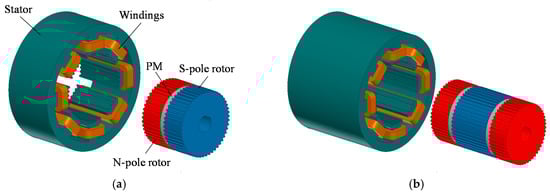
Figure 1.
Configuration of the 2-phase 8-pole 50-rotor-tooth hybrid stepping motor (HSM). (a) Single PM and two rotor stacks; (b) Multiple PMs and rotor stacks.
An equivalent transformation from the normal HSM to the novel SHSM is shown in Figure 2. Figure 2a,b show the schematic end view of the HSM. By symmetry, Figure 2a can be divided into two identical parts, i.e., I = II, so for Figure 2b III = IV. Supposing the rotor in Figure 2b rotates one-half a tooth pitch, and simultaneously all the stator windings are inversely supplied, then Figure 2c can be obtained. It can be seen that Figure 2c is exactly equivalent to Figure 2b, and that it can be identically divided into two parts, i.e., V = VI. Interestingly, Figure 2a has the same rotor position as that of Figure 2c. It is suitable to select one part of each, e.g., part I and part VI, and assemble them together to constitute a novel motor structure, in which the polarities of both the stator and rotor poles can be produced by using two PMs symmetrically embedded in the stator yoke and magnetized in the opposite direction, as shown in Figure 2d; thus, the novel SHSM is finally obtained. It should be emphasized that the saturated magnetic bridge shown in Figure 2d is usually adopted to keep the stator lamination sheets in one piece and solve problems in series manufacturing while maintaining the very small desired air-gap, and that the width of the magnetic bridge is designed to be as small as possible to reduce the PM flux leakage.
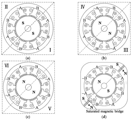
Figure 2.
Evolution from the traditional HSM to the novel SHSM. (a) N-pole rotor end of the HSM; (b) S-pole rotor end of the HSM; (c) Equivalent form of (b); (d) The novel SHSM.
2.2. Topologies and Operational Principle
Multiple motor topologies are available to the SHSM, due to various combinations of the stator, rotor teeth, and stator PMs. Figure 3 shows two typical combinations for analysis.
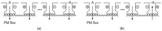
Figure 3.
Schematic diagram of motor topologies. (a) Topology 1; (b) Topology 2.
Supposing that m is the number of phases, p is the number of stator poles per phase, n is the number of PMs, and Zr is the number of rotor teeth, the motor topologies can be expressed as follows:
- For topology 1, p must be a multiple of 4, n = p/2, and,
- For topology 2, p must be an even number and m ≥ 3, n = p, and,
where k and j are positive integers which include the motor topologies in [18,19].
The proposed SHSM has the same operational principle as that of the HSM, due to structure equivalent transformation. Figure 4 shows the theoretical waveforms of the PM flux ψpm and current i of one phase with respect to the rotor position θ (electrical angle), and,
where Im is the amplitude of the phase current, and δ is the torque angle [19].
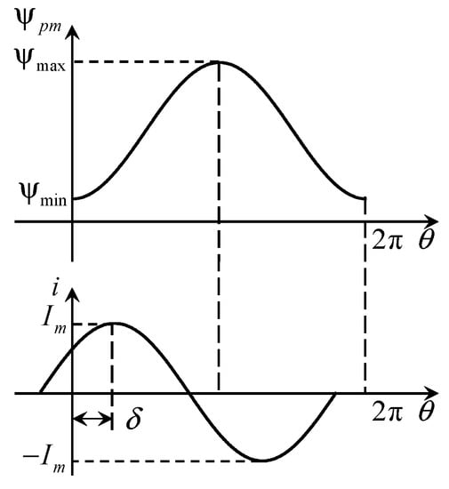
Figure 4.
Theoretical waveforms of the PM flux and current of one phase.
The energy stored in the magnetic field can be expressed as
where Wpm is the PM energy, Ww is the winding energy at I, I = [ia, ib,..., im]T is the matrix of phase currents, and L = [Lxy] (x = a, b,..., m; y = a, b,..., m) is the matrix of phase inductances. By employing the coenergy method, the expression of the total torque T is obtained as [5,21]
in which ψ = LI + ψpm is the matrix of total fluxes produced by the phase currents and PMs, ψpm = [ψpma, ψpmb, , ψpmm]T is the matrix of the PM fluxes, Tpm is the PM torque component due to the interaction between the phase current and the PM flux, Tr is the reluctance torque component due to the variation of inductances, and Tcog is the cogging torque (detent torque) due to the variation of the PM energy with respect to the rotor position. According to Equations (5)–(8), Tpm can be derived when the m phases are energized with sinusoidal currents as
2.3. Performance Superiorities
Compared to the conventional HSM, the novel SHSM with structure innovation has advantages in following aspects:
- PMs are embedded in the stator yoke, and a single-stack rotor is merely required, thus the manufacturing difficulties and costs are reduced.
- The PM magnetic circuit is located in the radial-circumferential plane, which eliminates the defects that the PM flux has to go vertically through, such as the core laminations and inter-lamination air-gaps [2]. As a result, the utilization rate of PMs and core materials is improved, which increases the output torque and power for the given current.
- The axial length of the motor can be chosen at any range since the number of core laminations has nothing to do with the utilization rate of the PMs, hence the motor’s power grade can be easily enhanced by simply increasing the core stack length.
- It is easier to realize the heat dissipation of the PMs which are embedded in the stator, such as the protection of the PMs [16].
- The PM and current magnetic field are coupled in the same radial-circumferential plane. A 2-D distribution of electromagnetic field can thus be considered for the motor design and analysis assuming a negligible end effect, which proves to be time-saving and features high accuracy.
All the above advantages make it possible to not only be applied in the high-precision positioning systems like an HSM, but also in the high-power electromechanical energy conversion areas like a DSPM motor. Moreover, when taking into account the open-loop control advantage for the motor-drive system, the novel SHSM will have a favorable position in competitions with other types of motor.
3. Performance Comparison between HSM and SHSM
3.1. PM Flux Density
Based on the operational principle of the HSM and the SHSM, the PM torque Tpm is proportional to ∆ψpm once the motor structure and current excitation are determined, and ∆ψpm can be derived as
where Nph is the phase winding turns, Zs is the stator teeth per stator pole, and ϕTmax and ϕTmin represent the tooth-layer PM flux at the tooth-tooth position and tooth-gap position, respectively. Figure 5 shows the relationships of ∆ϕT, ϕTmax, and ϕTmin with respect to the air-gap PM flux density Bpm obtained by 2-D FEA, in which t is the tooth width, g is the air-gap length, and λ is the tooth pitch. It can be found that ∆ϕT reaches its maximum value ∆ϕTmax when Bpm = Bpm0, signifying the maximum PM torque according to Equations (9) and (10), and Bpm0 can thus be defined as the optimal PM flux density.
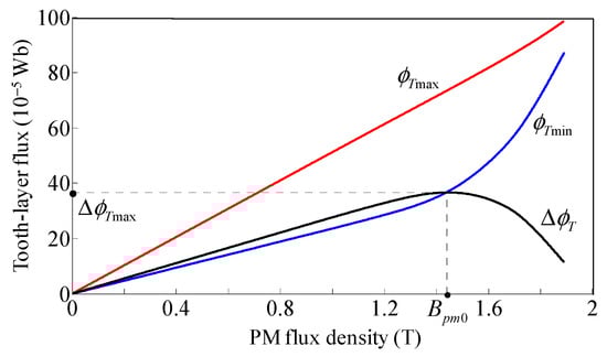
Figure 5.
Relationships of ∆ϕT, ϕTmax, and ϕTmin with respect to Bpm at t = 0.4 mm, g = 0.05 mm, λ = 1 mm.
In terms of [2,18], the axial distribution of Bpm along the stator core length in the HSM (with single PM and two rotor stacks) is non-uniform and would take the form of Figure 6, where hpm is the PM height in the magnetizing direction, taking into account the inter-lamination air-gaps. On the contrary, the axial distribution of Bpm along the stator core length is uniform in the SHSM, which can be designed as Bpm0 by using 2-D FEA or even the more accurate 3-D FEA.
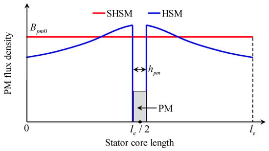
Figure 6.
Axial distribution of the PM flux density.
3.2. PM Torque
According to Figure 6, the optimal stator core length, corresponding to Bpm0 and the maximum Tpm, can be chosen at any range in the SHSM. Nevertheless, the situation is more complex when it comes to the HSM. For convenience, the simplest configuration of HSM, one with a single PM and two rotor stacks, is taken into account and analyzed. As shown in Figure 1, the PM surface area Spm is restricted by the inner and outer rotor diameter, resulting in limited PM flux. As a result, there exists an optimal stator core length le0 corresponding to the maximum Spm and Tpm, which can be determined by using 3-D FEA, taking into account the inter-lamination air-gaps, the saturation effect, and the end effect.
Figure 7 shows the axial distribution of the PM torque density of the two motors based on Figure 6, in which Tpm0 represents the maximum PM torque of the unit stator core length (1 m) corresponding to the optimal PM flux density Bpm0, l1 and l2 represent the axial position where the PM flux density of the two motors are the same, and the shaded area represents the torque losses of the HSM compared to the SHSM.
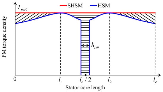
Figure 7.
Axial distribution of the PM torque density.
Supposing that le is the actual stator core length, according to the axial distribution characteristics of PM flux density and PM torque density shown in Figure 6 and Figure 7, the PM torque comparison between the HSM and the SHSM is carried out in three cases:
- le ≤ le0/2. Bpm is almost uniformly distributed in the HSM, and Spm can be suitably selected to make Bpm = Bpm0, thus the torque density ratio of the two motors is ρ = (le − hpm)/le.
- le0/2 < le ≤ le0. Bpm is non-uniformly distributed in the HSM, and Spm can be suitably selected to make the average value of Bpm equal to Bpm0, thus ρ = (le − Ss/Tpm0)/le, where Ss is the shaded area as shown in Figure 7.
- le > le0. Multiple PMs and rotor stacks can be used in the HSM to improve the torque producing capability. Supposing that Npm is the number of PMs, ρ can be determined by either case1 as ρ = (le − Npmhpm)/le when le/Npm ≤ le0/2 or case2 as ρ = (le − NpmSs/Tpm0)/le when le0/2 < le/Npm ≤ le0.
Consequently, the SHSM benefits from the advantages of higher output torque (power) density than the HSM, no matter what the motor’s configuration and stack length is.
3.3. Stator Core Saturation Issue
The 2-D electromagnetic field distribution can bring the advantage of higher torque density to the SHSM as analyzed above. However, it will inevitably cause the additional saturation issue of the stator core compared with the HSM, due to the different magnetic field distribution characteristics of the two motors. The magnetic field analysis in terms of the stator pole and stator yoke of the two motors is carried out, taking the 2-phase 8-pole 50-rotor-tooth motor configuration, as shown in Figure 8. The stator pole and yoke region under investigation and the positive direction of magnetic flux are shown in Figure 8a,b. Moreover, the simplified equivalent magnetic circuits corresponding to half of the HSM in Figure 8a and the whole SHSM in Figure 8b are built [18], as shown in Figure 9.
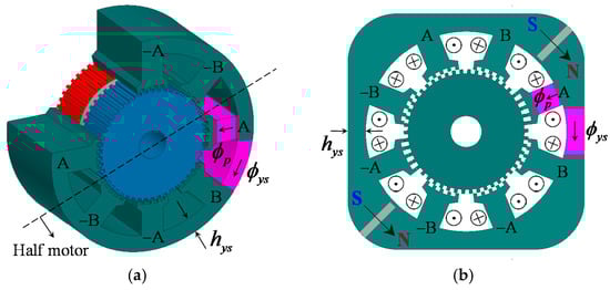
Figure 8.
Configuration of the 2-phase 8-pole 50-rotor-tooth HSM and SHSM. (a) HSM; (b) SHSM.
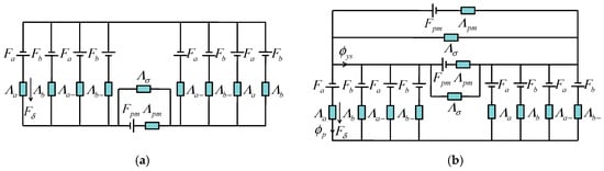
Figure 9.
Simplified equivalent magnetic circuits of the two motors. (a) Half of the HSM; (b) SHSM.
The parameters are defined as follows: ϕp is the total magnetic flux passing the stator pole; ϕys is the total magnetic flux passing the stator yoke; Fa = Npia and Fb = Npib are the magnetomotive force (MMF) sources of the winding currents, where Np is the winding turns per stator pole; Fpm is the MMF source of the PM; Fδ is the air-gap MMF drop of the PM; Λpm and Λσ are the main and leakage permeance of the PM; and Λa, Λb, Λa−, and Λb− are the parallel tooth-layer permeances at different stator poles.
The magnetic circuits show in Figure 9 can be solved according to the derivation process in Appendix A, and the ϕp and ϕys are given as
Assuming that the two motors have the same stator pole width wp and minimum stator yoke thickness hys (as shown in Figure 8), the maximum flux density of the stator pole Bpmax and stator yoke Bysmax can be determined according to Equation (11) and compared as
where c = Λt1/Λt0 can be determined in terms of [5], and c < 0.6 at the range of g/λ = 0.02–0.1. It indicates that the maximum flux density of the stator pole and yoke region of the SHSM is higher than that of the HSM, whether the phase windings are energized or not. In other words, the SHSM suffers higher stator core saturation than the HSM, which may influence the operation performance, e.g., reducing the maximum output torque to a certain extent.
3.4. Detent Torque and Positional Holding Accuracy
In the SHSM, any two stator poles separated by 180° are of inverse symmetry and have the same electromagnetic properties, as shown in Figure 8b. Moreover, the air-gap PM flux density of the stator poles nearer to the PMs is higher than that of the others, due to the shorter PM magnetic circuit. Therefore, the actual air-gap PM MMF drop of the stator poles nearer and farther from the PMs can be approximately determined as (Fδ + ∆F) and (Fδ − ∆F), where ∆F is the extra MMF drop considering the asymmetrical distribution of the PM magnetic circuit. As a result, the detent (cogging) torque of the HSM and the SHSM can be expressed according to the derivation in Appendix B as
Accordingly, the maximum value of the detent torque of the two motors is compared as
Since sinusoidal currents are employed for driving the motor, the drive must be based on the so-called micro-stepping principle [22]. In the open-loop operation, assuming that the ideal sinusoidal currents ia = Imcos (θ + δ), ib = Imsin (θ + δ) are employed, the ideal micro-step angle is infinitesimal, and then the relationships with respect to the given rotor position θ, given load torque Tl, given torque angle δ, and actual rotor position θ’ can be derived in terms of Equations (8) and (9) as
where ∆θ = θ’ − θ represents the positional holding accuracy, as schematically shown in Figure 10.
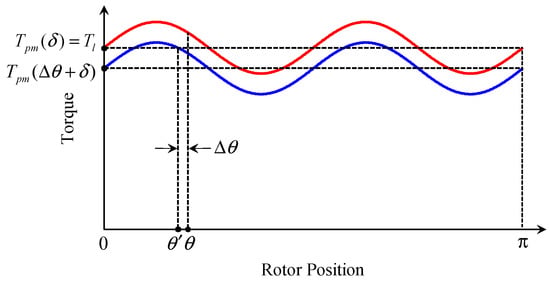
Figure 10.
Schematic diagram of the positional holding accuracy.
3.5. PM Grade, PM Flux Leakage, and PM Utilization Rate
As it is known, the temperature rise of magnets located on the stator is much easier to control than those located on the rotor [16]. Therefore, the requirements for temperature rise of PMs can be reduced in the SHSM. In addition, much more installation space is available for the PMs embedded in the stator yoke, especially for the motor configuration with more than two PMs. As a result, the PM width in the radial length and PM height in the magnetizing direction can be increased to achieve the same PM flux; that is to say, the utilized PM grade or cost would be reduced. Taking the 2-phase 16-pole 100-rotor-tooth SHSM for instance, its configurations with high-grade (high residual flux density Br and high coercive force Hc) and low-grade PMs are schematically shown in Figure 11.
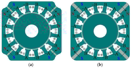
Figure 11.
Configurations of the 2-phase 16-pole 100-rotor-tooth SHSM. (a) With high-grade PMs; (b) With low-grade PMs.
Unlike the DSPM motor [16], the saturated magnetic bridge (see Figure 2d) is usually adopted in the SHSM to keep the stator lamination complete and to solve problems in series manufacturing due to the small desired air-gap. Although the magnetic bridge works in highly saturated conditions, the relative permeability of the bridge is still higher than the PMs (nearly equal to air), which can be proved by the nonlinear FEA. As a result, it suffers from the defect of relatively high flux leakage of the PMs embedded in the stator of the SHSM, which would reduce the PMs’ utilization rate.
Comparison of the PM utilization rate between HSM and SHSM is analyzed by taking the 2-phase 8-pole 50-rotor-tooth configuration as a example. Figure 12 provides the simplified equivalent magnetic circuits for the PM, in which Rlam is the total reluctance of the core laminations along the axial direction taking into account the inter-lamination air-gaps, and supposing that ϕm and ϕσ are the main and leakage flux of the PM, and ϕδ is the air-gap flux. The magnetic leakage factor σ can be defined as σ = ϕm/ϕδ [23].
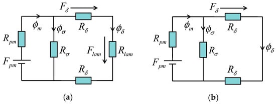
Figure 12.
Simplified equivalent magnetic circuits for the PM of the two motors. (a) HSM; (b) SHSM.
Assuming that Rpm, Rδ, and ϕδ of the two motors are designed to be the same [19], ϕm can be thus obtained as
Moreover, Rpm can be expressed as Rpm = (Hchpm)/(BrSpm), thus the ratio of the total utilized PM volume of the two motors is derived as
It indicates that the SHSM benefits from the advantage of the higher PM utilization rate and therefore PM volume-saving compared to the HSM under the condition that the PM leakage factor of the two motors is designed to be nearly the same.
4. Experimental and FEA Verification
To verify the operation feasibility and the theoretical analysis of the proposed SHSM, a 2-phase 8-pole 50-rotor-tooth prototype machine has been fabricated for experimentation as shown in Figure 13, and the associated nonlinear FEA has also been carried out. The detailed specifications and main design parameters of the prototype machine are listed in Table 1.
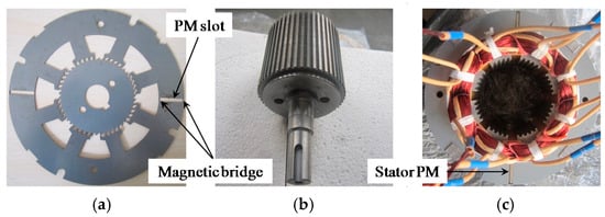
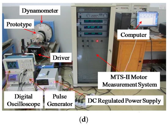
Figure 13.
Prototype of the proposed 2-phase 8-pole 50-rotor-tooth SHSM. (a) Core laminations; (b) Rotor; (c) Stator and windings; (d) Experimental setup.

Table 1.
Design specifications of the prototype machine.
4.1. Experiments
Figure 14 shows the calculated and measured waveform of the no-load back electromotive force (EMF). It can be found that the amplitude of the calculated one (about 24.5 V) is slightly greater than that of the measured one (about 22 V), mainly due to the fact that the motor’s end effect is neglected in the 2-D FEA. To take the end effect into account, the end coefficient kend can be adopted to modify the calculated results [24], which can be determined as kend = 0.9 according to the results in Figure 14.
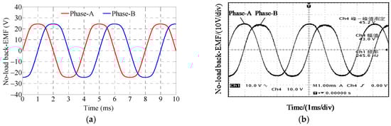
Figure 14.
No-load back-EMF of the prototype at the speed 300 r/min. (a) 2-D FEA; (b) Measured.
The transient current can be derived as [18,24]
where R and L are respectively the winding resistance and inductance, Rs is the sampling resistance used for detecting the winding currents, and ωr is the mechanical angular velocity, UDC is the DC-bus voltage. Supposing that Ig is the given current amplitude and Ti = 2π/(Zrωr) is the current period time, in the initial state when the current i is established from I0 = 0, the actual current amplitude Im applied to the phase winding can be approximately expressed as
where the coefficients kE and kL represent the amplitude of (dψpm/dθ) and (dL/dθ), respectively.
In the designed motor-drive system, the required parameters are measured: R = 1.2 Ω (at room temperature), L = 16.6 mH (in average), Rs = 0.5 Ω, UDC = 300 V, and the given current amplitude is Ig = 4.2 A. Moreover, the values of kE and kL can be determined by 2-D FEA as kE = 0.7 and kL = 0.024. Both the calculated and measured current-speed characteristics of the prototype are shown in Figure 15a. It can be seen that the calculated result coincides well with the experimental one.
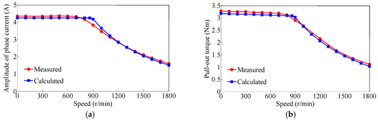
Figure 15.
Current and torque-speed characteristics of the prototype. (a) Current-speed characteristic; (b) Torque-speed characteristic.
Based on the current-speed characteristic, the maximum pull-out torque at different speeds can be calculated by 2-D FEA. In addition, the torque-speed characteristic can be measured by adding maximum load to the prototype at different speeds via the MTS-II Motor Measurement System as shown in Figure 13d. Figure 15b shows the comparison of the calculated and measured torque-speed characteristics, supposing a negligible friction factor and taking into account the end effect. It can be seen that the calculation result can well predict the measured one, which is of significant importance in computing the motor’s dynamic performance.
4.2. FEA Results
To verify the theoretical analysis and evaluate the performance of the proposed SHSM, two comparative FEM models are established. One is the SHSM with the configuration shown in Figure 8b and the parameters shown in Table 1, apart from the fact that the stator outer diameter is changed to 125 mm and the PM radial length is changed to 34 mm, aimed to achieve the optimal PM flux density Bpm0. The other one is the HSM with the configuration shown in Figure 8a and the same dimensions as the SHSM except for the PM surface area. The two models have the same stator pole width wp = 12 mm, stator yoke thickness hys = 12.5 mm, and the same stacking factor kFe = 0.95.
4.2.1. PM Flux Density and Pull-Out Torque
Figure 16 shows the comparison of the PM flux density characteristics, in which the calculation results of the HSM are obtained by 3-D FEA, whilst the optimal PM flux density Bpm0 = 1.4 T of the SHSM is determined by 2-D FEA. For Npm = 1, the maximum PM surface area is selected, and the calculated results can well verify the theoretical analysis. For Npm = 2, the PM surface area is adjusted to obtain the similar PM flux density characteristic to the SHSM.
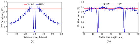
Figure 16.
Comparison of PM flux density characteristics. (a) Npm = 1; (b) Npm = 2.
Figure 17a shows the comparison of the pull-out torque under rated currents with δ = π/2. It can be seen that the average pull-out torque of the HSM reaches about 4.8 N·m when Npm = 2, which is still lower than that of the SHSM of about 5.5 N·m. The FEA calculated pull-out torque density ratio is about ρ = 0.87, which coincides well with the theoretical one ρ = (le − Npmhpm)/le = 0.9. In addition, the unequal-tooth-pitch method [9] is usually adopted to reduce the torque ripples for stepping motors accordingly, and the pull-out torque calculation results with λs = 6.8° (stator tooth pitch) and λr = 7.2° (rotor tooth pitch) are shown in Figure 17b.
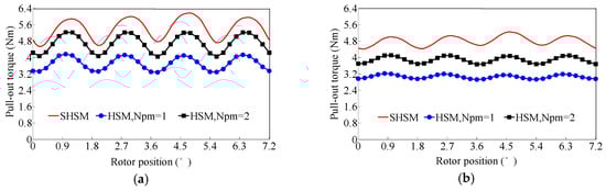
Figure 17.
Comparison of pull-out torque properties. (a) Equal tooth-pitch; (b) Unequal tooth-pitch.
4.2.2. Stator Core Saturation and Holding Torque
Figure 18 shows the comparison of flux density in the stator pole and stator yoke region by using the analytical method and FEA. Λt0 and Λt1 in Equation (11) can be accurately determined as Λt0 = 8.1 × 10⁻⁶ (Wb/A) and Λt1 = 2.4 × 10⁻⁶ (Wb/A) by 2-D FEA [18,25], and Fδ = gBpm0/µ0 = 280 A. It can be seen that the analytical method can well predict the flux variation in the stator pole and yoke region, although some errors occur mainly due to the saturation effect.
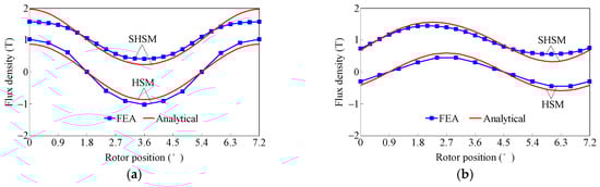
Figure 18.
Comparison of stator core flux density. (a) Flux density in the stator pole; (b) Flux density in the stator yoke.
The FEA results show that the stator core saturation level of the HSM is lower than that of the SHSM due to the existence of the axial PM magnetic circuit, which verifies the theoretical analysis. Further discussion should be carried out with regards to this flux density comparison. For the SHSM, the total magnetic flux generated by winding currents and PMs is distributed in the same radial-circumferential plane, and the calculated results can well reflect the actual stator core saturation level. Nevertheless, for the HSM, the flux is non-uniformly distributed in the stator pole and yoke region, due to the 3-D distributed PM field and the influence of inter-lamination air-gaps, thus the calculated results can only reflect the average stator core saturation level. To investigate the actual flux distribution characteristic of the HSM, and to reasonably evaluate the influence of the stator core saturation on the torque producing ability, much more research regarding the magnetic field calculations and analyses needs to be performed by using 2-D and 3-D FEA, which will be presented in future works.
In this work, a comparison of the holding torque is carried out under the most idealized situation, namely, the saturation effect of the stator core except for the stator tooth region which is neglected in the HSM, with the results shown in Figure 19. It can be found that the torque difference of the two models increases almost linearly in region I, due to the lower iron saturation. In region II, the torque difference is almost unchanged, due to the influence of the relatively higher stator core saturation of the SHSM. In region III, the holding torque hardly increases and even decreases due to the oversaturation of the tooth-layer (see Figure 5), whereas the torque difference rises again since the tooth-layer saturation level of the SHSM is lower than that of the HSM due to the high saturation of the stator pole and yoke.
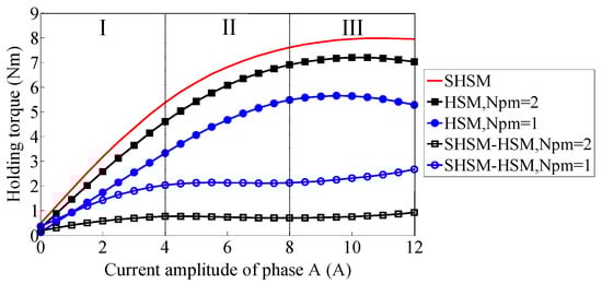
Figure 19.
Comparison of the holding torque.
4.2.3. Detent Torque and Positional Holding Accuracy
Figure 20 shows the comparison of detent torque (Npm = 2 in the HSM) obtained by the analytical method and FEA. Λt4 and ∆F in Equations (13)–(15) are determined as Λt4 = 2.5 × 10⁻⁸ (Wb/A) and ∆F = 5 A by 2-D FEA. It can be seen that the detent torque of the SHSM is non-uniformly distributed in a tooth-pitch cycle and is slightly higher than that of the HSM due to the asymmetric distribution of the PM magnetic circuit, and the analytical calculation can well predict this variation, which verifies the theoretical analysis. In addition, the primary 4th harmonic torque component can be effectively reduced by using the unequal-tooth-pitch method.
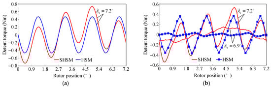
Figure 20.
Comparison of the detent torque. (a) Analytical; (b) FEA.
Figure 21 shows the comparison of the positional holding accuracy obtained by FEA according to Equation (16). It can be seen that the positional holding accuracy (∆θ) of the SHSM is lower than that of the HSM due to the higher torque ripple, especially under the unequal-tooth-pitch situation. On the other hand, the ∆θ shown in Figure 21b can hardly be improved in the open-loop operation, since the ideal sinusoidal currents have been employed and the torque ripple can hardly be reduced. In other words, the micro-stepping driving mode reaches the highest positioning accuracy of about ∆θ = 0.11° (HSM) and ∆θ = 0.22° (SHSM) for the specific torque angle δ even with infinite subdivisions, due to the limitations of the motor structure and operation principle.
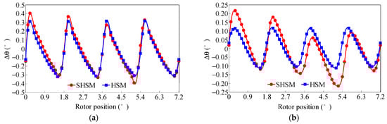
Figure 21.
Comparison of the positional holding accuracy with the given torque angle δ = π/3. (a) Equal tooth pitch, λs = λr = 7.2°; (b) Unequal tooth pitch, λs = 6.9°, λr = 7.2°.
4.2.4. PM Flux Leakage and PM Utilization Rate
Figure 22 gives the PM flux leakage of the SHSM obtained by 2-D FEA. It can be seen that the leakage factor takes the value of σ = 1.1–1.16 at g = 0.1–0.25 mm without the magnetic bridge, which is much smaller than that of the DSPM motor [23] due to the very small desired air-gap. Moreover, it increases almost linearly with respect to the magnetic bridge thickness tbge to about the same value of σ = 1.46 at tbge = 3 mm. On the other hand, the utilized PM volume with g = 0.1 mm (which is the more general design case) is reduced significantly more than that with g = 0.25 mm due to the decrease of Rδ according to Equations (17) and (18), indicating a much higher PM utilization rate.
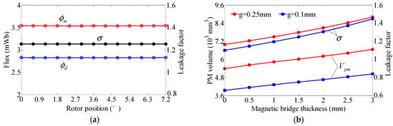
Figure 22.
PM flux leakage and utilized PM volume of the SHSM. (a) g = 0.25 mm, tbge = 1.5 mm; (b) g = 0.1–0.25 mm, tbge = 0–3 mm.
4.2.5. Mechanical Force Analysis
For the requirements of practical application, it is of high necessity to conduct the mechanical force analysis for the SHSM due to the asymmetrical excitation of the PM location. Taking the SHSM in Figure 8b for instance, any two stator poles separated in angle by 180° have the same tooth-tooth position, the same PM field intensity, and the same superimposed excitation by the PMs and winding currents. As a result, these two stator poles would suffer the mechanical force with same magnitude and opposite direction according to Equation (8), and therefore the motor’s resultant force is zero. Figure 23 shows the 2-D FEA calculation results, which verifies the theoretical analysis.
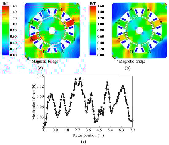
Figure 23.
Mechanical force analysis of the SHSM. (a) Magnetic field distribution with PMs only; (b) Magnetic field distribution with phase-A energized; (c) Stator mechanical force during operation.
5. Conclusions
This paper presented a novel stator-permanent-magnet hybrid stepping motor (SHSM). Taking a comprehensive consideration of the theoretical analysis, FEA simulations, and experimental studies, the following conclusions can be obtained:
- The proposed SHSM has the same operational principle and control method as the traditional HSM, with superiorities such as simpler rotor structure, easier manufacturing and PM cooling, higher mechanical robustness, higher PM utilization rate, and higher torque, power density, and power grade.
- The proposed SHSM benefits from a 2-D distributed electromagnetic field nature, which simplifies the design, analysis, and calculations for this kind of machine with a relatively high accuracy and time-saving advantages.
- The proposed SHSM suffers from higher stator core saturation and higher detent torque and torque ripple compared with the HSM, since the total flux generated by the PMs and winding currents is distributed in the same radial-circumferential plane and is mutually superimposed, and the PM magnetic circuit is asymmetrically distributed with respect to the PMs, which may lead to a reduction of operation performance to certain extent.
- The proposed SHSM suffers from relatively lower positioning accuracy compared with the HSM, especially under the unequal-tooth-pitch situation, and therefore it is more suitable for electro-mechanical energy conversion applications rather than positioning mechanisms.
Acknowledgments
This work was supported in part by the Foundation of National High Technology Research and Development Program of China (863 Program) under Projects 2015AA042307.
Author Contributions
Binglin Lu mainly conducted the analysis of the proposed stator-permanent-magnet hybrid stepping motor (SHSM) and performed the experiments and FEA simulations. The manuscript was improved and revised by Yanliang Xu.
Conflicts of Interest
The authors declare no conflict of interest.
Appendix A. Magnetic Circuits Solution
The solving process of the magnetic circuits shown in Figure 9 is derived as follows:
where Λt0 and Λt1 are the constant and fundamental permeance components of one tooth-layer, and the PM height hpm is neglected. Assuming that the relative permeability of the iron core is infinity, the superposition principle can be applied to the magnetic circuits. Firstly, setting the phase currents ia = 0 and ib = 0, the flux ϕ and ϕ produced by the PM alone can be obtained as
Assuming that the mutual inductance can be neglected, then the flux ϕ and ϕ produced by the winding currents alone can be approximately obtained when the two phases are energized with the sinusoidal currents ia = Imcos (θ + δ) and ib = Imsin (θ + δ), i.e.,
Appendix B. Detent Torque Calculation
In terms of [5], the stored PM energy Wpm in the air gap of the two motors can be expressed as
Accordingly, the detent (cogging) torque can be determined by Equation (8).
References
- Umans, S.D. Fitzgerald & Kingsley's Electric Machinery, 7th ed.; McGraw-Hill: New York, NY, USA, 2013; pp. 495–503. [Google Scholar]
- Kosaka, T.; Pollock, C.; Matsui, N. 3 Dimensional finite element analysis of hybrid stepping motors taking inter-lamination gap into account. In Proceedings of the 2004 International Conference on Power Electronics, Machines & Drives (PEMD), Edinburgh, UK, 31 March–2 April 2004; pp. 534–539. [Google Scholar]
- Betin, F.; Pinchon, D.; Capolino, G.-A. Fuzzy logic applied to speed control of a stepping motor drive. IEEE Trans. Ind. Electron. 2000, 47, 610–622. [Google Scholar] [CrossRef]
- Tsui, K.W.-H.; Cheung, N.C.; Yuen, K.C.-W. Novel modeling and damping technique for hybrid stepper motor. IEEE Trans. Ind. Electron. 2009, 56, 202–211. [Google Scholar]
- Matsui, N.; Nakamura, M.; Kosaka, T. Instantaneous torque analysis of hybrid stepping motor. IEEE Trans. Ind. Appl. 1996, 32, 1176–1182. [Google Scholar] [CrossRef]
- Stuebig, C.; Ponick, B. Comparison of calculation methods for hybrid stepping motors. IEEE Trans. Ind. Appl. 2012, 48, 2182–2189. [Google Scholar] [CrossRef]
- Jenkins, M.K.; Howe, D.; Birch, T.S. An improved design produce for hybrid stepper motors. IEEE Trans. Magn. 1990, 26, 2535–2537. [Google Scholar] [CrossRef]
- De Silva, C.W. Design equations for tooth distribution of stepping motors. IEEE Trans. Ind. Electron. 1990, 37, 184–196. [Google Scholar] [CrossRef]
- Rajagopal, K.R.; Singh, B.; Singh, B.P. Optimal tooth-geometry for specific performance requirements of a hybrid stepper motor. IEEE Trans. Magn. 2003, 39, 3010–3012. [Google Scholar] [CrossRef]
- Liao, Y.; Liang, F.; Lipo, T.A. A novel permanent magnet motor with doubly salient structure. IEEE Trans. Ind. Appl. 1995, 31, 1069–1078. [Google Scholar] [CrossRef]
- Cheng, M.; Chau, K.T.; Chan, C.C. Static characteristics of a new doubly salient permanent magnet motor. IEEE Trans. Energy Convers. 2001, 16, 20–25. [Google Scholar] [CrossRef]
- Deodhar, R.P.; Andersson, S.; Boldea, I.; Miller, T.J.E. The flux reversal machine: A new brushless doubly-salient permanent-magnet machine. IEEE Trans. Ind. Appl. 1997, 33, 925–934. [Google Scholar] [CrossRef]
- More, D.S.; Fernandes, B.G. Analysis of flux-reversal machine based on fictitious electrical gear. IEEE Trans. Energy Convers. 2010, 25, 940–947. [Google Scholar] [CrossRef]
- Hua, W.; Cheng, M.; Zhang, G. A novel hybrid excitation flux-switching motor for hybrid vehicles. IEEE Trans. Magn. 2009, 45, 4728–4731. [Google Scholar] [CrossRef]
- Cao, R.; Cheng, M.; Zhang, B. Speed control of complementary and modular linear flux-switching permanent-magnet motor. IEEE Trans. Ind. Electron. 2015, 62, 4056–4064. [Google Scholar] [CrossRef]
- Cheng, M.; Hua, W.; Zhang, J.; Zhao, W. Overview of stator-permanent magnet brushless machines. IEEE Trans. Ind. Electron. 2011, 58, 5087–5101. [Google Scholar] [CrossRef]
- Zhang, J.; Cheng, M.; Chen, Z.; Hua, W. Comparison of stator-mounted permanent-magnet machines based on a general power equation. IEEE Trans. Energy Convers. 2009, 24, 826–834. [Google Scholar] [CrossRef]
- Lu, B.; Xu, Y. Presentation and analysis of a novel hybrid stepping motor with stator-permanent-magnet structure. In Proceedings of the 2015 International Conference on Electrical Machines and Systems (ICEMS), Hangzhou, China, 25–28 October 2015; pp. 869–875. [Google Scholar]
- Lu, B.; Xu, Y.; Ma, X. Design and analysis of a stator-permanent-magnet hybrid stepping motor. IEEE Trans. Appl. Supercond. 2016, 26, 1–5. [Google Scholar] [CrossRef]
- Sakamoto, M.; Tozune, A. High torque 2 phase hybrid type stepping motor. In Proceedings of the 2005 International Conference on Electrical Machines and Systems (ICEMS), Nanjing, China, 27–29 September 2005; pp. 630–634. [Google Scholar]
- Chau, K.T.; Sun, Q.; Fan, Y.; Cheng, M. Torque ripple minimization of doubly salient permanent-magnet motors. IEEE Trans. Energy Convers. 2005, 20, 352–358. [Google Scholar] [CrossRef]
- Freitas, M.A.A.; Andrade, D.A.; Borges, T.T. Driving the step motor with controlled phase currents. In Proceedings of the 1998 International Conference on Power Electronic Drives and Energy Systems for Industrial Growth (PEDES), Perth, Australia, 1–3 December 1998; pp. 493–498. [Google Scholar]
- Cheng, M.; Chau, K.T.; Chan, C.C. Design and analysis of a new doubly salient permanent magnet motor. IEEE Trans. Magn. 2001, 37, 3012–3020. [Google Scholar] [CrossRef]
- Zhu, X.; Cheng, M. Design, analysis and control of hybrid excited doubly salient stator-permanent- magnet motor. Sci. China Ser. E Technol. Sci. 2010, 53, 188–199. [Google Scholar] [CrossRef]
- Stuebig, C.; Ponick, B. Determination of air gap permeances of hybrid stepping motors for calculation of motor behavior. In Proceedings of the 2008 International Conference on Electrical Machines (ICEM), Vilamoura, Portugal, 6–9 September 2008; pp. 1–5. [Google Scholar]
© 2017 by the authors. Licensee MDPI, Basel, Switzerland. This article is an open access article distributed under the terms and conditions of the Creative Commons Attribution (CC BY) license (http://creativecommons.org/licenses/by/4.0/).