Abstract
This paper proposes a single-loop repetitive voltage control strategy which incorporates the active damping control feature for single-phase uninterruptible power supply (UPS) applications. The proposed method reduces the effect of the LC resonant peak, which limits the control bandwidth and deteriorates the stability of the entire control loop by effectively increasing the damping component. Due to the increased stability margin, a repetitive controller working together with a proportional-resonant (PR) controller can be easily adopted. Moreover, the voltage error is minimized even under severe non-linear load conditions. It is confirmed that the proposed single-loop controller achieves excellent and stable voltage regulation performance by evaluating the entire loop-gain of the system and the output impedance. Both the simulation and the experimental results for a 1.5 kW UPS inverter show agree well with the analyses, and the excellence of the proposed method has been verified.
1. Introduction
Uninterruptible power supplies (UPSs) are employed to protect critical loads from a short or long interruption [1,2,3,4,5]. One of the main control purposes of a UPS is precisely regulating the output voltage, keeping it as sinusoidal as possible with a low total harmonic distortion (THD). Fast dynamic characteristics are essentially required in transient state. In order to implement a high-performance voltage controller in a UPS, a number of individual control loops are needed and the structure of the controllers should be carefully established. Regarding a number of the control loops, either a single- or a multi-loop structure have been popularly utilized [6]. A single-loop structure has only a single voltage control loop whereas a multi-loop structure includes both voltage and current control loops individually. It has been well-known that multi-loop structures exhibit stable control characteristics, because the instability in the control loop caused by an undamped LC resonant peak can be successfully mitigated due to the operation of the current controller. It has been also found that the capacitor current feedback method in multi-loop voltage control strategies has better transient characteristics then using the inductor current feedback scheme [7]. However, the multi-loop structure has a control delay caused by its cascaded arrangement. Meanwhile, a single-loop structure can be a good candidate for voltage control as long as the resonant peak can be properly damped, and its stability margin can be secured. The reasons are that a single-loop structure is more intuitive and introduces less control delay, enabling larger phase margin of the control loop. Moreover, the implementation of a single-loop structure is relatively easier compared to that of multi-loop structures. In [2,8], a single-loop voltage control method based on μ-synthesis has been proposed. The extended Lyapunov-function-based control strategy was proposed in [9]. In terms of the control structure, various control algorithms have been proposed. Among them, repetitive controllers have been popularly employed in UPS and grid-tied inverter applications, because periodic voltage error can be significantly reduced [10,11,12,13]. In [14], the single-loop direct repetitive control strategy was proposed. In that method, the inverse function of the power stage model is cascaded in the voltage control loop to suppress the LC resonance. By doing so, the stability of the whole control loop could be improved. In [15], Lu has proposed the single-loop repetitive control scheme with reduced sampling numbers. The capacitor voltage feedback based active damping technique was incorporated with the repetitive controller for three-phase UPS controlled under synchronous-frame [16].
In this paper, a single-loop voltage control strategy is proposed for UPS applications. The proposed method is based on the active damping control technique using the inductor current feedback with a weighting factor to suppress the high LC resonant peak. From this, the phase margin of the open-loop gain is significantly improved compared to the one without the active damping control. After that, both the PR and the repetitive controllers are simultaneously applied to achieve highly accurate voltage regulation. Thanks to the increase of the stability margin, the performance of the PR and the repetitive voltage controllers can be maximized by achieving enough control gain. Detailed analyses including the output impedance and the root trajectories in the z-domain are performed for the proposed control scheme. Both the simulation and the experimental results on the single-phase UPS prototype demonstrate the excellent performance of the proposed method.
2. System Description
Figure 1 shows the single-phase UPS inverter dealt in this paper. It consists of the dc source Vdc, the full-bridge inverter, which consists of four switching devices, and the LC filter.
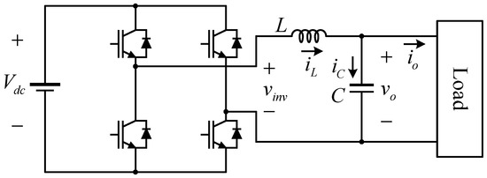
Figure 1.
Single-phase UPS inverter system.
The open-loop dynamics of the output voltage vo are represented as:
where L, C, vinv, and io represent the filter inductance, the filter capacitance, the inverter output voltage, and the load current, respectively. From (1), the open-loop output impedance Zo(s) is defined as follows:
Equation (2) estimates how the output voltage is affected by the shape or the magnitude of the load current. The relationship between vinv and vo except considering io is written as seen below.
As can be expected in Equations (2) and (3), the frequency responses of Zo(s) and Gvo(s) show that they inherit the characteristics of band-pass and low-pass filters without damping coefficients, respectively.
Figure 2 compares Zo(s) and Gvo(s) in the frequency domain with the given parameters, L = 2.9 mH and C = 120 μF. In order to reduce the output voltage distortion caused by the load current, |Zo(s)| should be as low as possible. However, |Zo(s)| is getting enlarged before the resonant frequency, 269.8 Hz. This means that high order harmonic components affect the shape of the output voltage. For the high frequency range over the resonant frequency, the magnitude of the output impedance is reduced. However, such a high frequency region where the high frequency current is already attenuated by the LC filter is not of interest in practice. From Figure 2, the phase margin of Gvo(s) can be evaluated as 0°. This means the output voltage may see an extremely severe oscillation during a transient. The main reason is that the phase changes rapidly around the resonant frequency. In fact, it is well-known that the resonance should be dampened to stabilize a voltage control loop. One popular approach is employing a voltage controller cascaded with an inner inductor current controller. However, the inner current loop may introduce an iteration delay, and it could deteriorate the transient performance.
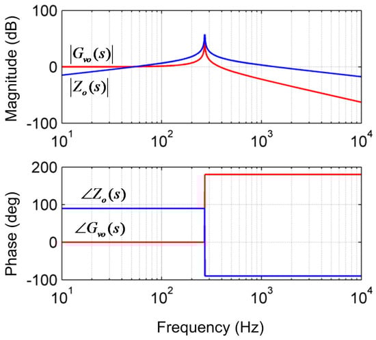
Figure 2.
Frequency responses of Gvo(s) and Zo(s).
3. Proposed Single-Loop Voltage Control Strategy with the Active Damping Control
The concept of the active damping control is represented in Figure 3. Here, is the output voltage commanded by the feedback voltage controller which will be detailed in the later paragraphs. Since Figure 3 only deals with the control scheme, the dynamic properties of the digital pulse-width-modulation process have been ignored. As can be seen in the figure, the inductor current iL is measured, and the active damping gain Kd is multiplied. After that, it is subtracted from the output of the feedback controller vfb. Hence, the following equation can be established:
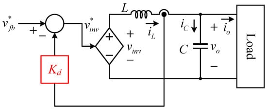
Figure 3.
The concept of the active damping control.
From this, the relationship between vo and vfb is rewritten as seen in Equation (5).
Compared to Equation (3), the damping coefficient is existent in the form of the multiplication of Kd and C as in Equation (5). Since C is a fixed value in an inverter system, the damping coefficient can be adjusted by selecting the value of Kd. Figure 4 illustrates the frequency responses of Equation (5) with different Kd. Equation (5) and Figure 4 clearly indicates that the damping factor of the transfer function can be affected by Kd. With Kd = 0, no damping coefficient is realized, so that high resonant peak persists. As the value of Kd increases, the resonant peak is attenuated, and no resonance can be achieved even in theory. It should be mentioned that the phase margin is secured with increasing Kd. This means the voltage loop with the active damping control can be more stable compared to that without Kd.
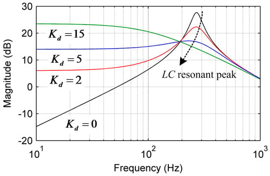
Figure 4.
Comparison of the output impedance under different Kd.
Figure 5 shows the proposed single-loop repetitive voltage control scheme. The output voltage and the inductor current are measured. The feedback controller consists of the PR and the repetitive controllers. The fundamental 60 Hz component is mainly handled by the PR controller while harmonics are eliminated using the repetitive controller. The PR and the repetitive controllers in the z-domain are realized as follows:
where Kp, Kr, ωc, ωo, and Ts are the proportional gain, the resonant gain, the damping coefficient, the resonant frequency, and the sampling period, respectively, and
where Krp, N, and α represent the repetitive control gain, the entire number of samples in one electrical cycle, and the number of samples for the angle advance to improve the stability of the control loop [17]. Here, the zero-phase delay low pass filter q(z) in Equation (7) can be written as seen below to prevent a high frequency noise [18].
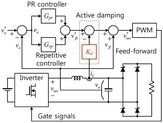
Figure 5.
Proposed single-loop repetitive voltage control scheme with the active damping control.
In Figure 5, the feed-forward voltage vff is directly added, and it compensates for the admittance effect in the entire control loop [19]. With this configuration, the voltage error eo between the voltage reference and vo is characterized as follows:
From (9), the output impedance reflecting the proposed control structure is obtained as per Equation (10).
As can be supposed in Equations (9) and (10), the damping coefficient of the entire control loop can be actively adjusted by Kd. Consequently, the resonant peak caused by the LC filter can be easily mitigated by increasing Kd as described in Figure 4, and the control loop can be easily stabilized. One simple approach to determine Kd is using the fact that there is no resonant peak in the frequency response in a generalized second order transfer function when the damping ratio of the transfer function is larger than the unity value. By applying this rule to Equation (5), the criterion to select Kd is derived as follows:
By substituting the given parameters, L = 2.9 mH and C = 120 μF, into Equation (11), the minimum Kd without the resonant peak is calculated as 9.83. However, this does not guarantee a stable performance under the proposed control structure, because the entire stability highly relies on the co-operation with the other controllers, especially the repetitive controller.
For a maximum value of Kd, it may be reasonable to establish the assumption that the active damping component, Kd iL, should be less than the maximum synthesizable voltage physically with the given power stage. From this, the constraint as below can be written:
where Mmax and ILpk are the maximum achievable modulation index and the peak value of the inductor current under full load condition. Since the maximum output power of the power stage in this paper is 1.5 kW, ILpk is simply calculated as 9.64 A. By choosing Vdc and Mmax as 400 V and 0.9, the maximum allowable Kd is obtained as 37.34. In sum, the range of Kd considering the experimental parameters is represented as:
Figure 6 compares the output impedances in the z-domain under the different control structures with the following parameters: Kp = 10, Kr = 25, ωc = 62.8 rad/s, ωo = 377 rad/s, Ts = 50 μs, Kd = 35, Krp = 2.5, N = 333, and α = 2. In the figure, Zorg(z), Zopr(z), and Zorep(z) represent the output impedances without any controller, with the active damping and the PR controller, and with all controllers including the repetitive control. Usually, the output impedances of a UPS should be as low as possible in both the fundamental and the harmonic frequencies to minimize the voltage distortion in wide frequency ranges. For Zorg(z), the magnitude at the fundamental frequency 60 Hz is acceptable, but the high resonant peak is observed near the 5th order harmonic range. Although no severe resonant peak exists with Zopr(z), there is no magnitude attenuation at each harmonic frequency. The best performance is expected with Zorp(z) in Figure 6, because multiple notches which have extremely low magnitudes exist at the fundamental and the harmonic frequencies.
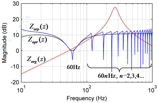
Figure 6.
Comparison of the output impedances under different control structures.
Next, the stability of the entire control loop should be evaluated, and the transfer function shown in Equation (14) can be utilized for this purpose [17]:
where Gvo(z) is the z-domain expression of the open-loop control-to-output voltage transfer function Gvo(s) as expressed in Equation (5).
According to the small gain theorem, the condition below should be satisfied up to the Nyquist frequency to stabilize the control loop [17,20].
Figure 7 shows how the active damping control improves the stability of the entire control loop. In order to evaluate it, the trajectories for the roots of H(z) under different Kd are examined. Note that the repetitive control gain Krp is fixed to 2.5. As shown in the figure, the trajectory stays inside the unit circle with Kd = 35, and it is expected that the control loop is apparently stable. However, when Kd is zero, the trajectory violates the border of the unit circle, so that a stable operation cannot be guaranteed.
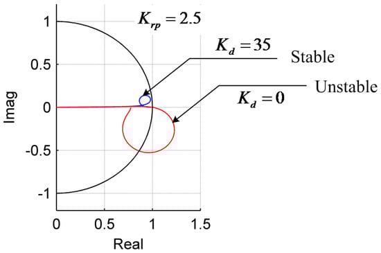
Figure 7.
Trajectories for the roots of H(z) under different Kw.
Figure 8 illustrates the maximum value of |H(z)| when Krp and Kd are changed in the given range. Here, Krp is evaluated from 1 to 4, and Kd is adjusted from 0 to 40. For convenience of the view, the magnitude of |H(z)| is only expressed up to 1.0. If the maximum |H(z)| is equal or higher than 1.0, it means that the root trajectory passes the border of the unit circle. Hence, it is a necessary condition that the maximum value of |H(z)| should be less than the unity for stable operation.
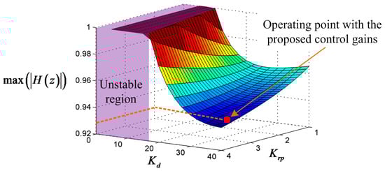
Figure 8.
The maximum value of |H(z)| under different Krp and Kd.
In Figure 8, it is supposed that a controller with Kd less than roughly 20 can easily become unstable regardless of Krp. Apparently, higher Kd brings lower the maximum value of |H(z)| with a given Krp. It is also interesting that higher Krp induces lower amplitude of |H(z)|. However, this does not mean achieving better stability with higher Krp, because the stability margin of the entire control may be reduced. As can be seen in Figure 8, a stable operation of the entire control loop is expected from the selected control gains, Kd = 35 and Krp = 2.5. In sum, the step-by-step flowchart for selecting the active damping and the repetitive control gains are shown in Figure 9.
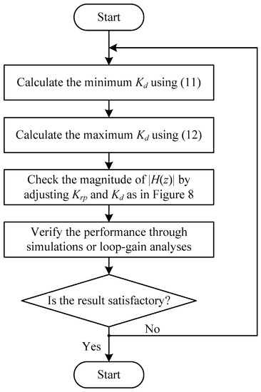
Figure 9.
Design procedure of the active damping and the repetitive control gains.
4. Simulation Results
In order to examine the performance of the proposed algorithm, a simulation study has been conducted. For the simulation, PSIM 9.0 software from Powersim Inc. (Rockville, MD, USA) has been utilized. Figure 10 represents the nonlinear load configuration used in the simulation and the experiments which will be discussed in the later section. Here, the output voltage reference is 220 V in root-mean-square value. The repetitive voltage controller is implemented as in Figure 11. All system parameters including the PR and the repetitive controllers are selected to be identical as the ones described in Section 2 and Section 3. Since the controllers are realized in the digital controller, the digital delay effects, 1.5Ts, have been considered.
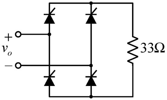
Figure 10.
Configuration of the load used in the simulation and the experiments.
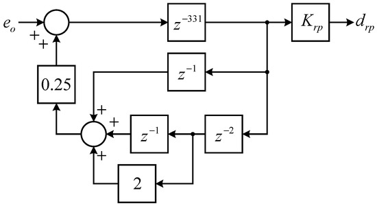
Figure 11.
The block diagram of the repetitive controller.
Figure 12 compares the simulation results with different Kd. The conduction angle of the thyristor bridge is selected as 30° in the simulation. In order to clearly show the load current, the scaling factor 20 was multiplied to the original value. In Figure 12a, Kd was selected as 14. In the figure, the output voltage is eventually diverged. Obviously, the voltage controller cannot be stabilized. However, the output voltage in Figure 12b where Kd was chosen as 35 is very well regulated as we have analyzed before.
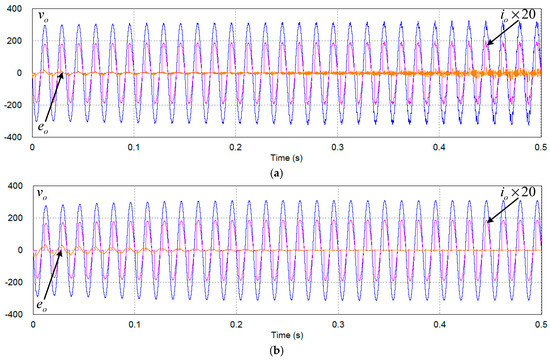
Figure 12.
Simulation results using the proposed method with different Kd. (a) Kd = 14; (b) Kd = 35.
Figure 13 shows the simulation results with different load configurations. At the beginning, the same nonlinear load with previous simulations is utilized, but the conduction angle is adjusted to be 90°. It should be noticed that this is the most severe condition for the UPS hardware and the controller, because the no-load and the full-load conditions in step are continuously repeated. As illustrated in the figure, there is no significant distortion or instability. At t = 0.2 s, the no-load condition is applied in step. The output voltage shows a slight voltage overshoot, but it is recovered in a half cycle. At t = 0.304 s, the 1.5 kW linear load is connected, and the output voltage is very well regulated.
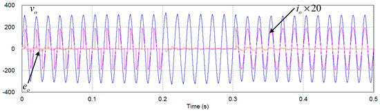
Figure 13.
Simulation results of the UPS system with different load configurations.
Figure 14 shows the zoomed-in waveforms of Figure 10 and Figure 11 for 0.45 s < t < 0.5 s. The figure clearly indicates that the control performance with Kd = 35 is much better than another one. In order to analyze these results, the root trajectories of H(z) with different Kd are compared in Figure 15. In the figure, the trace of root moving with Kd = 14 contacts the border of the unit circle. This means the entire control loop cannot be stabilized under this condition, because the small gain theorem expressed in Equation (13) is violated.
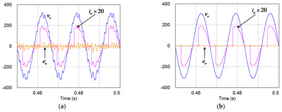
Figure 14.
Zoomed in waveforms of the simulation results. (a) Kd = 14; (b) Kd = 35.
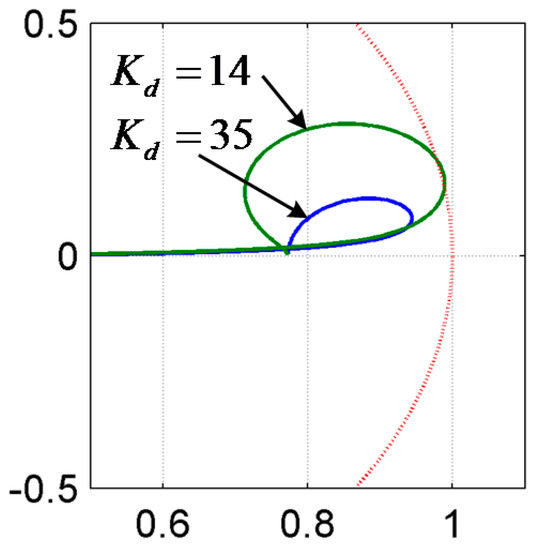
Figure 15.
The root trajectories of H(z) with different Kd.
5. Experimental Results
The experiments have been carried out to verify the effectiveness of the proposed active damping based controller design scheme. Figure 16 shows the single-phase UPS inverter prototype. For the switching device, Infineon’s 600 V class IGBT module devices are employed. The control algorithms are implemented in the 32-bit floating point digital signal processor (DSP), TMS320F28335 from Texas Instruments, Dallas, TX, USA. The DSP board contains a 4-channel digital-to-analog converter (DAC), so that the control variables can be easily monitored via an oscilloscope. The same load configuration in Figure 9 is built, and only the load resistance is adjusted. The dc input of the inverter is fed by a dc power supply, and Vdc is adjusted to be 400 V.
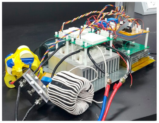
Figure 16.
Developed single-phase inverter prototype.
Figure 17 shows the experimental result without the active damping control. As can be expected from the analysis in Figure 7, the single-loop PR and the repetitive controllers never achieve stable operation without the active damping scheme. For the test, the gains of the PR and the repetitive controllers have been tuned to avoid divergence of vo. In Figure 17, the oscillatory voltage response is generated by the low control bandwidth, low damping, and high LC resonant peak. Both the output voltage and the current contain severe harmonic components.
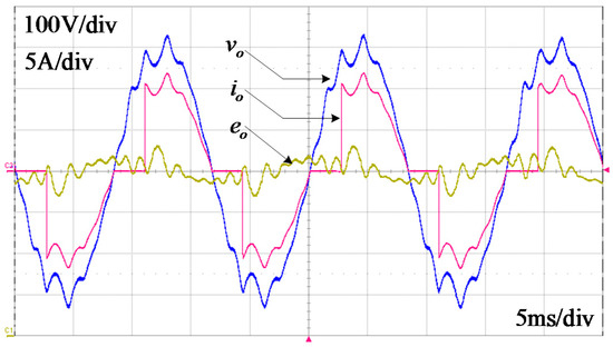
Figure 17.
Experimental result without the active damping control.
The experimental result with the active damping control with Kd = 35 is shown in Figure 18. Now, the control gains and parameters are recovered as analyzed in the previous sections. In contrast with the case in Figure 17, the output voltage vo is very well regulated and stable, and the voltage error eo is also well restrained in Figure 18. There is no severe voltage dip on vo even in the rapid current transient because of the stable operation of the active damping and the repetitive control.
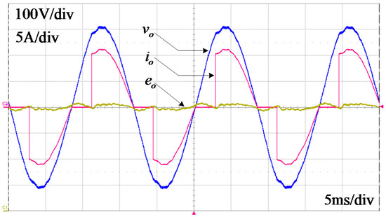
Figure 18.
Experimental result with the active damping control.
In Figure 19, the load step change condition is tested. At the beginning, no load operation is performed. At t = 11 ms, the nonlinear load is connected. Even under this condition, no significant voltage error is detected. Although the peak of the output voltage is slightly reduced, it is gradually recovered because of the operation of the repetitive controller.
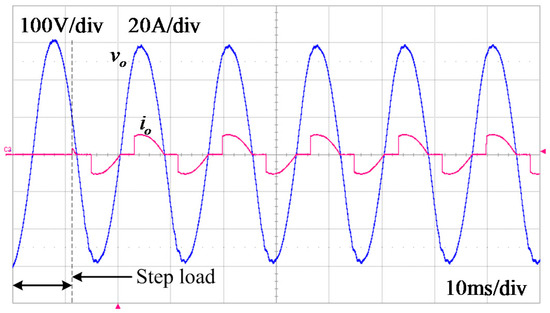
Figure 19.
Experimental result under the load step change condition.
6. Conclusions
This paper proposes a single-loop voltage control strategy based on active damping control for single-phase UPS systems. The proposed method easily suppresses the effect of the high resonant peak caused by the physical LC filter in the entire control loop. By doing so, it is possible to maximize the control bandwidth of the PR and the repetitive controllers compared to traditional single-loop controllers with poor damping characteristics. In addition, the control loop can be easily stabilized in both the no-load and the full-load conditions. Compared to a multi-loop structure, more intuitive loop analysis can be performed, because there are no inner loop dynamics in the proposed method. Furthermore, less computation delay is expected, so a low THD on the output voltage is achieved. Both the simulation and the experimental results show that the proposed method achieves stable and accurate voltage control performance even under severe nonlinear load conditions.
Acknowledgments
This work was supported by the “Human Resources Program in Energy Technology” of the Korea Institute of Energy Technology Evaluation and Planning (KETEP), granted financial resource from the Ministry of Trade, Industry & Energy, Korea (No. 20164030201100) and “Basic Science Research Program” through the National Research Foundation of Korea (NRF) funded by the Ministry of Education (NRF-2014R1A1A2058883).
Author Contributions
Younghoon Cho provided the idea and the system implementation, and wrote this paper. Byeng-Joo Byen performed the experiments. Han-Sol Lee and Kwan-Yuhl Cho assisted the idea development and the paper writing.
Conflicts of Interest
The authors declare no conflict of interest.
References
- Hirachi, K.; Nakaoka, M. Ups circuit configuration incorporating buck-boost chopper circuit with two magnetically coupled coils. Electron. Lett. 2003, 44, 443–444. [Google Scholar] [CrossRef]
- Ji, J.-K.; Ku, D.-K.; Lim, S.-B. Low cost and high performance single phase ups using a single-loop robust voltage controller. J. Power Electron. 2015, 15, 695–701. [Google Scholar] [CrossRef]
- Lazzarin, T.B.; Bauer, G.A.T.; Barbi, I. A control strategy for parallel operation of single-phase voltage source inverters: Analysis, design and experimental results. IEEE Trans. Ind. Electron. 2013, 60, 2194–2204. [Google Scholar] [CrossRef]
- Sekar, A.; Raghavan, D. Implementation of single phase soft switched PFC converter for plug-in-hybrid electric vehicles. Energies 2015, 8, 13096–13111. [Google Scholar] [CrossRef]
- Zhang, P.; Cai, H.; Zhao, H.; Shi, J.; He, X. Line-interactive ups for low-voltage microgrids. J. Power Electron. 2015, 15, 1628–1639. [Google Scholar] [CrossRef]
- Vandoorn, T.L.; Ionescu, C.M.; Kooning, J.D.M.D.; Keyser, R.D.; Vandevelde, L. Theoretical analysis and experimental validation of single-phase direct versus cascaded voltage control in islanded microgrids. IEEE Trans. Ind. Electron. 2013, 60, 789–798. [Google Scholar] [CrossRef]
- Loh, P.C.; Newman, M.J.; Zmood, D.N.; Holmes, D.G. A comparative analysis of multiloop voltage regulation strategies for single and three-phase ups systems. IEEE Trans. Power Electron. 2003, 18, 1176–1185. [Google Scholar]
- Kahrobaeian, A.; Mohamed, Y.A.-R.I. Direct single-loop μ-synthesis voltage control for suppression of multiple resonance in microgrids with power-factor correction capacitors. IEEE Trans. Smart Grid 2013, 4, 1151–1161. [Google Scholar] [CrossRef]
- Komurcugil, H.; Altin, N.; Ozdemir, S.; Sefa, I. An extended lyapunov-function-based control strategy for single-phase UPS inverters. IEEE Trans. Power Electron. 2015, 30, 3976–3983. [Google Scholar] [CrossRef]
- Abusara, M.A.; Sharkh, S.M.; Zanchetta, P. Control of grid-connected inverters using adaptive repetitive and proportional resonant schemes. J. Power Electron. 2015, 15, 518–529. [Google Scholar] [CrossRef]
- Lei, W.; Nie, C.; Chen, M.; Wang, H.; Wang, Y. A fast-transient repetitive control strategy for programmable harmonic current source. J. Power Electron. 2017, 17, 172–180. [Google Scholar] [CrossRef]
- Trinh, Q.-N.; Lee, H.-H. Versatile upqc control system with a modified repetitive controller under nonlinear and unbalanced loads. J. Power Electron. 2015, 15, 1093–1104. [Google Scholar] [CrossRef]
- Yang, S.; Wang, P.; Tang, Y.; Zhang, L. Explicit phase lead filter design in repetitive control for voltage harmornic mitigation of vsi-based islanded microgrids. IEEE Trans. Ind. Electron. 2017, 64, 817–826. [Google Scholar] [CrossRef]
- Zhang, K.; Kang, Y.; Chen, J. Direct repetitive control of SPWM inverter for UPS purpose. IEEE Trans. Power Electron. 2003, 18, 784–792. [Google Scholar] [CrossRef]
- Lu, W.; Zhou, K.; Wang, D.; Cheng, M. A generic digital nk ± m-order harmonic repetitive control scheme for pwm converters. IEEE Trans. Ind. Electron. 2014, 61, 1516–1527. [Google Scholar] [CrossRef]
- Jiang, S.; Cao, D.; Li, Y.; Liu, J.; Peng, F.Z. Low-THD, fast-transient, and cost-effective synchronous-frame repetitive controller for three-phase UPS inverters. IEEE Trans. Power Electron. 2012, 27, 2994–3005. [Google Scholar] [CrossRef]
- Cho, Y.; Lai, J.-S. Digital plug-in repetitive controller for single-phase bridgeless PFC converters. IEEE Trans. Power Electron. 2013, 28, 165–175. [Google Scholar]
- Zhou, K.; Wang, D. Digital repetitive controlled three-phase pwm rectifier. IEEE Trans. Power Electron. 2003, 18, 309–316. [Google Scholar] [CrossRef]
- Cho, Y.; Mok, H.; Lai, J.-S. Analysis of the admittance component for digitally controlled single-phase bridgeless pfc converter. J. Power Electron. 2013, 13, 600–608. [Google Scholar] [CrossRef]
- Mattavelli, P.; Tubiana, L.; Zigliotto, M. Torque ripple reduction in pm synchronous motor drives using repetitive current control. IEEE Trans. Power Electron. 2005, 20, 1423–1431. [Google Scholar] [CrossRef]
© 2017 by the authors. Licensee MDPI, Basel, Switzerland. This article is an open access article distributed under the terms and conditions of the Creative Commons Attribution (CC BY) license (http://creativecommons.org/licenses/by/4.0/).