Article

Performance Comparison between Selected Evaporative Air Coolers

1
Department of Environmental Engineering, Wroclaw University of Science and Technology, 50-370 Wroclaw, Poland
2
Department of Control Systems and Mechatronics, Wroclaw University of Science and Technology, 50-370 Wroclaw, Poland
*
Author to whom correspondence should be addressed.
Energies 2017, 10(4), 577; https://doi.org/10.3390/en10040577
Submission received: 13 January 2017 / Revised: 16 April 2017 / Accepted: 17 April 2017 / Published: 22 April 2017

Abstract

:
The aim of this study is to determine which of the heat exchangers is characterized by the highest efficiency in different applications. Various types of evaporative air coolers were compared: a typical counter-flow unit, the same unit operating as a heat recovery exchanger, a regenerative unit and a novel, modified regenerative exchanger. The analysis includes comparing the work of evaporative heat exchangers during summer and winter season. The analysis is based on the original mathematical models. The numerical models are based on the modified ε-NTU (number of heat transfer units) method. It was established that selected arrangements of the presented exchangers are characterized by the different efficiency in different air-conditioning applications. The analysis faces the main construction aspects of those evaporative coolers and also compares two above-mentioned devices with modified regenerative air cooler, which can partly operate on cooled outdoor airflow and on the exhaust air from conditioned spaces. This solution can be applied in any climate and it is less dependent on the outdoor conditions. The second part of the study focuses on winter season and the potential of recovering heat with the same exchangers, but with dry working air channels. This allows establishing their total potential of generating energy savings during the annual operation.

1. Introduction

The rise in living standards is leading to increased air-conditioning demand, especially in the summer time in high temperature areas. It is necessary to develop new sources of cooling, which could be less dependent on electric energy. The use of indirect evaporative cooling is a relatively new method of cooling air in air-conditioning systems which looks very promising, both in terms of reduced electricity consumption and in the area of using less ozone depleting refrigerants, since its working medium is water. One of the most effective cooling solutions for indirect evaporative air-cooling are the counter-flow cycles [1,2,3]. Those air coolers can be arranged in a variety of configurations. The most “classical” solutions are a typical counter-flow exchanger and a regenerative counter-flow exchanger [4]. The regenerative heat exchanger can also use different variants of perforation along its channel plate [5]. The counter-flow exchanger can operate as a heat recovery unit in conjunction with a standard cooling coil from mechanical compression system. This solution can be applied in any climate and it is less dependent on the outdoor conditions. To make regenerative exchangers less dependent on the ambient air parameters, a desiccant wheel can be applied to the system [6]. The last system is a novel combination of heat recovery counter-flow exchanger operating with cooling coil and a regenerative heat exchanger. The novel solution is a compromise between a regenerative exchanger and a counter-flow exchanger operating with a cooling coil. Less air is returned to the wet channel after passing through the exchanger, most of the airflow is delivered to the cooling coil where it can be additionally cooled and then to the conditioned space. After meeting the heating loads, the exhaust airflow is delivered to the working channels of the exchanger. Depending on the situation, more or less airflow can be returned directly after passing the exchanger to increase its temperature effectiveness. Therefore, during most time of its operation the device should be able to achieve high cooling capacity and low outlet temperatures.
The highest differences between temperatures of the ambient and indoor air can be observed in winter [7]. However, during operation in summer the temperature differences are much lower. Therefore, heat recovery units cannot recover much heat from the outdoor air in summer conditions. To overcome this disadvantage and provide low supply air temperatures with such units indirect-evaporative air cooling technique can be implemented in the typical counter-flow heat recovery exchangers. In the indirect evaporative air cooling heat exchanger (IEC), one side of the plate is covered with water. The other side of the plate remains dry. The plate is impenetrable, which prevents the water from contact with the dry part. During operation of such unit, water evaporates on the wet side of the plate where the working air stream passes. The primary air (in this case: outdoor air stream) passes across the dry side. Evaporation results in low temperature of the plate, which causes the heat transfer between the outdoor air and the plate and the air stream is cooled sensibly [8]. Implementation of indirect evaporative air cooling to the typical counter-flow heat recovery recuperator can result in significant energy savings. Operation during winter conditions is connected with an additional risk for any type of recuperator: when outdoor temperatures are very low, the frost can condensate on the plate surface of the heat exchanger. Frost on the plates can result in decrease in exchanger’s efficiency and it may eventually damage the plates [7]. That is why, a detail analysis is required to establish optimal geometrical and operation conditions for the indirect evaporative cooling and heat recovery unit, which would allow to keep highest effectiveness and guarantee safeness of year-round operation. The obtained results showed that the dehumidification capacity variation at the first stage had a direct impact on the cooling capacity obtained in the second stage of the process. As it can be seen from the literature analysis, the heat recovery exchangers and indirect evaporative air coolers have been intensively studied by many scientists.

1.1. Subject of the Study

Presented study focuses on two aspects: it tries to analyze advantages and disadvantages of application of different types of indirect evaporative air coolers in air conditioning applications and tries to study the aspect of round-year application of one, selected unit. Counter-flow exchanger was chosen to study its round-year operation, when it is operating as an indirect evaporative air cooler in summer and typical heat recovery exchanger in winter. Such exchanger can bring significant energy savings to the air-conditioning and ventilation systems and therefore reduce the operating and costs and produced pollution [9]. As for the analysis of different evaporative air coolers during summer conditions, six arrangements were chosen to analyze important aspects of their operation (Figure 1): stand-alone counter-flow unit, stand-alone regenerative flow unit, counter-flow units operating in supply-exhaust airflow arrangement with cooling coil (in this case exhaust air goes to the wet channel, unit can operate as a heat recovery exchanger during winter season), stand-alone perforated regenerative flow unit, stand-alone regenerative flow unit operating with a desiccant wheel and a novel heat exchanger which is a combination of regenerative unit and a counter-flow unit operating in supply-exhaust airflow regime. The study focuses on analysis of the indirect evaporative air coolers in different arrangements in air conditioning systems to establish the potential of their application and to establish in which arrangement evaporative air coolers achieve highest efficiency. The paper does not analyze the energy consumed by the system, because it can be significantly different, depending on the application (different climate conditions, different airflow rates, different cooling loads etc.). The operation of all of indirect evaporative air coolers presented in Figure 1 is simulated by original mathematical models.
The difference between in presented exchangers lies in their airflow arrangement, which allows achieving significantly different efficiency, even though the construction of the exchangers is similar. From the mathematical modeling standpoint the difference does not lie in the energy balance equations (all the exchangers realize counter-flow, which is modeled with the same type of equations), but with the boundary conditions for the heat and mass transfer process. The differences are visible as follows:
-
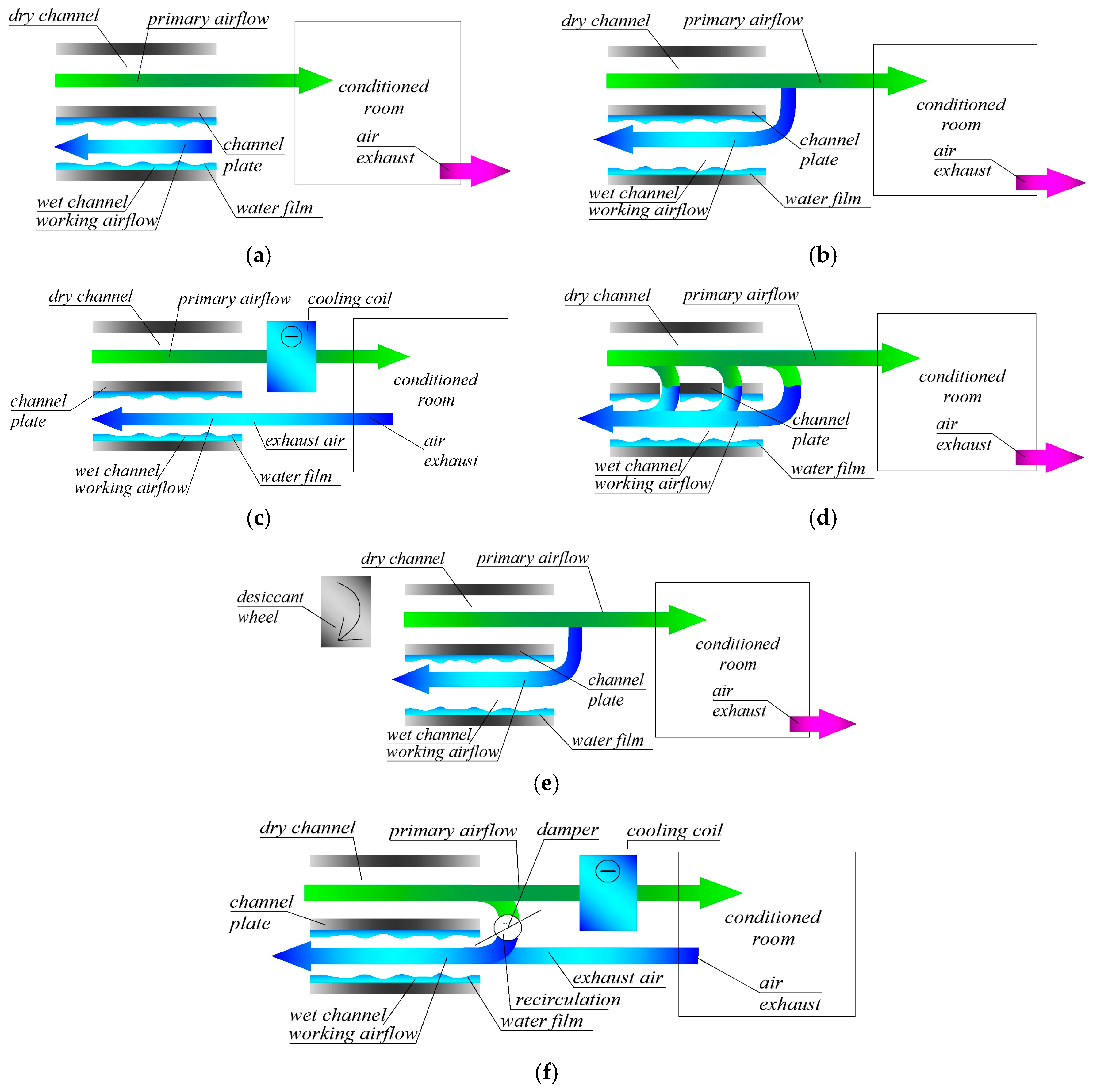
The typical counter-flow exchanger has separate intakes for primary and working air (Figure 1a,c). Therefore, both air streams can have different inlet parameters and different values of the airflow rate. This unit is not able to create a pre-cooling effect for the working air in the dry channel as regenerative unit (Figure 1b), but it can operate on the exhaust air in the systems with additional cooling coil (Figure 1c) and can have value of the airflow in the wet channel equal or higher to value of the airflow in the dry channel.
-
In the regenerative heat and mass exchanger a mixture of primary and working airflow is delivered to the dry channel (Figure 1b) and it passes the dry channel, where it is cooled. At the end of the dry channel primary and working airflow are separated, working airflow is delivered to the wet channel, while primary airflow is delivered to the occupants. Precooling of the working airflow in the dry channel allows to increase the efficiency of the exchanger, however, it also gives several disadvantages: regenerative unit cannot use exhaust air from the conditioned room, airflow delivered to the occupants is always smaller than the intake air (and airflow in the wet channel has to be smaller than the airflow in the wet channel. To increase the efficiency of the regenerative unit, a desiccant wheel can be added, to dehumidify the air before it passes the cooler (Figure 1e).
-
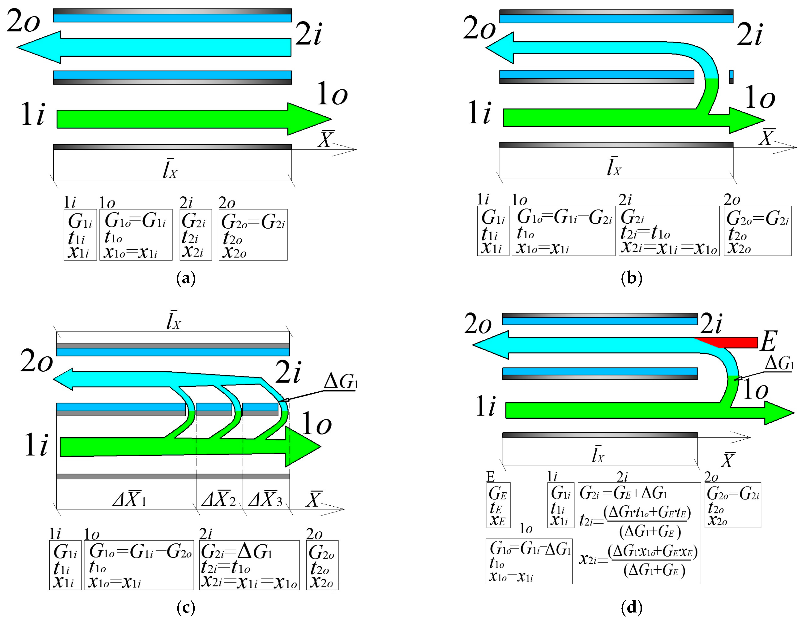
The perforated regenerative exchanger is similar to the regenerative exchanger, but in this unit, working air is delivered to the wet channel in portions instead of delivering whole value of the working air after it passes the dry channel as it is in case of the typical regenerative air cooler (Figure 1d). From the mathematical modeling standpoint, this unit requires additional algorithm describing the air streams mixing process (described in detail by authors in [5]).
-
The novel, modified exchanger is a combination of regenerative unit and a counter-flow unit (Figure 1f). It can operate on the exhaust air, but it can also return part of the airflow from the dry channel to the wet channel. Depending on the ambient and exhaust air conditions, proportions between air returned from the dry channel and the exhaust airflow can be changed to achieve highest effectiveness.

2. Methodologies

2.1. Model

The mathematical models developed to analyze the performance of indirect evaporative coolers are based on the modified ε–NTU method. In this method, the air stream in the matrix passages is considered to be a gaseous fluid flow with constant temperature, velocity and mass transfer potential (humidity ratio of the air) in the direction normal to the plate surfaces. It is assumed the bulk average values can be used for all variables. Due to the fact that authors presented such models in their previous papers, along with the detail transformation of the differential equations, this process will be omitted in this paper and only the basic form of the energy balance equations will be shown. All the detail information about the models are presented and analysis of the evaporative air coolers with the ε–NTU method is presented in papers previously published by authors: [2,3,4,5,8,10]. The basis of the method, including main heat transfer and flow characteristics assumptions, are presented in [4]. The main assumptions used in the model are listed in Table 1 for completeness.
In the perforated regenerative exchanger, the perforations are regularly distributed in the plate along the X-axis in each cross-section, three perforations were assumed (they are placed in sections X ¯ = X / L X = 0.33 ; 0.66 ; 1.0 , Figure 2b). In each cross-section of the X-axis, 1/3 of the total working air flow gets to the wet channel (regardless of the number of holes along the Y-axis). The basic explanation of the assumptions connected with analysis of the perforated air coolers was presented by Pandelidis and Anisimov in [5].
The energy balance equations are the same for all of analyzed indirect evaporative air coolers, the main difference lies in the calculating algorithm, which is different for the assumed exchangers. The model of perforated exchanger requires an additional algorithm describing the airflow mixing process. The algorithm was presented by the authors in [5]. Due to the fact that authors described the process of conversion the basic equations describing heat and mass transfer in indirect evaporative air coolers in detail in their previous studies [5], this process will be omitted in this study and only the final form of the equations will be presented. The governing equations for heat and mass transfer are discretized according to the modeled geometry shown in Figure 3. The following balance equations can be written for the air streams passing through control volume of the two HMXs (heat and mass exchangers-Figure 3):
  • The energy balance for the main air flow (see Figure 3a) is given as:
    G ˙ 1 c p 1 d t 1 d X d X = d Q ˙ 1 s = ( d Q ˙ p 1 s + d Q ˙ f i n 1 s )
    where G ˙ 1 = ( d Y / L Y ) G 1 .
  • The energy balance for the working air stream in the wet channel (see Figure 3a,b) is given as:
    G ˙ 2 c p 2 d t 2 d X d X = d Q ˙ 2 s + [ c g 2 ( t p 2 ' t 2 ) d M ˙ p 2 + c g 2 ( t ¯ f i n 2 t 2 ) d M ˙ f i n 2 ] = [ d Q ˙ p 2 s + d Q ˙ f i n 2 s ] + [ c g 2 ( t p 2 t 2 ) d M ˙ p 2 + c g 2 ( t ¯ f i n 2 t 2 ) d M ˙ f i n 2 ]
    where G ˙ 2 = ( d Y / L Y ) G 2 .
  • The mass balance equation for the water vapor inside the wet channel is given as:
    G ˙ 2 d x 2 d X d X = d M ˙ 2 = ( d M ˙ p 2 + d M ˙ f i n 2 )
The mathematical model also is supplemented by the energy balance equations for a differential control volume of the fins in the dry and wet channel [7] and the energy balance equations.
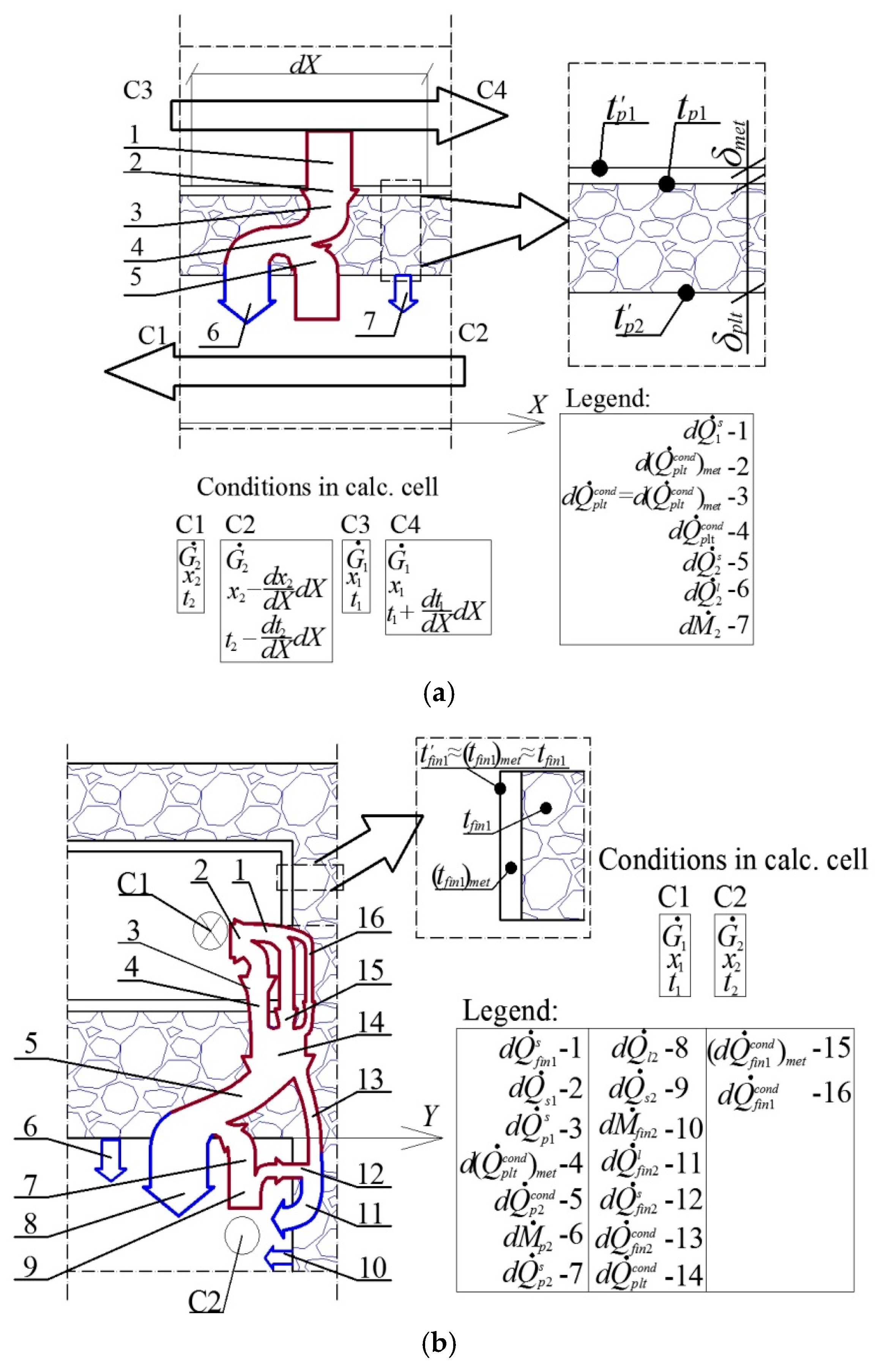
  • For the plate surface in the main air-flow channel (see Figure 3).
    d ( Q ˙ p l t c o n d ) m e t = d Q ˙ p 1 s
    Equation (4) can be converted using following set of equations:
    { d Q ˙ p l t c o n d = d ( Q ˙ p l t c o n d ) m e t + d Q ˙ f i n 1 c o n d   d Q ˙ f i n 1 c o n d = d ( Q ˙ f i n 1 c o n d ) m e t + d Q ˙ f i n 1 c o n d = d Q ˙ f i n 1 s
    to the form presented below:
    Q ˙ p l t c o n d = d Q ˙ p 1 s + d Q ˙ f i n 1 s
  • For the plate surface in the working air channel (see Figure 3):
    d Q ˙ p 2 c o n d + d Q ˙ p 2 s + d Q ˙ p 2 l
    This equation can be converted using the Equation (6) and the energy balance equation presented below:
    d Q ˙ p l t c o n d = d Q ˙ p 2 c o n d + d Q ˙ f i n 2 c o n d
    to the form:
    d Q ˙ f i n 2 c o n d = ( d Q ˙ p 1 s + d Q ˙ f i n 1 s ) + ( d Q ˙ p 2 s + d Q ˙ p 2 l )
    It should be noted that the iterative procedure of the boundary conditions assignment for the fin in the wet channel and local plate temperature computation at each node of integration step is considerably simplified using Equation (9).
To complete the set of differential Equations (i.e., (1), (2), (3), (8) and (9)) the initial conditions are needed (see Figure 2).
  • For the main air stream:
    t 1 | = t 1 i   X ¯ = 0   Y ¯ = 0 ÷ 1.0 ; x 1 | = x 1 i = c o n s t X ¯ = 0 ÷ 1.0   Y ¯ = 0 ÷ 1.0
  • For the working air stream:
    t 2 i | = t 1 o   X ¯ = 1.0   Y ¯ = 0 ÷ 1.0 ; x 2 i | = x 1 o = x 1 i   X ¯ = 1.0   Y ¯ = 0 ÷ 1.0  
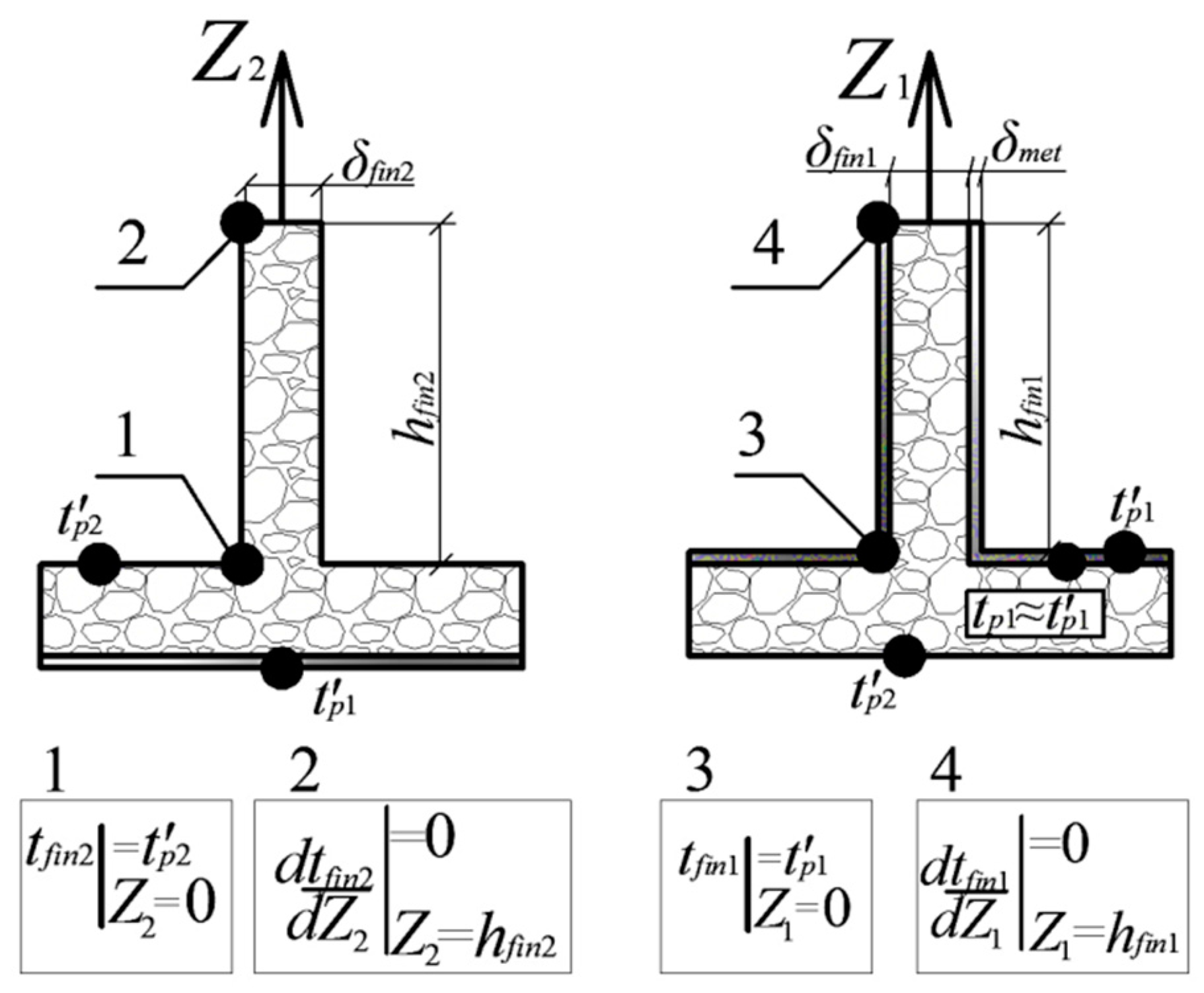
  • The boundary conditions for the fin in the working air-flow passage (Figure 4) are:
    t f i n 2 | = t p 2 = t p 2 Z ¯ 2 = 0   ; d t f i n 2 / d Z ¯ 2 | = 0   Z ¯ 2 = 1.0
  • And the boundary conditions for the fin in the main air-flow passage are:
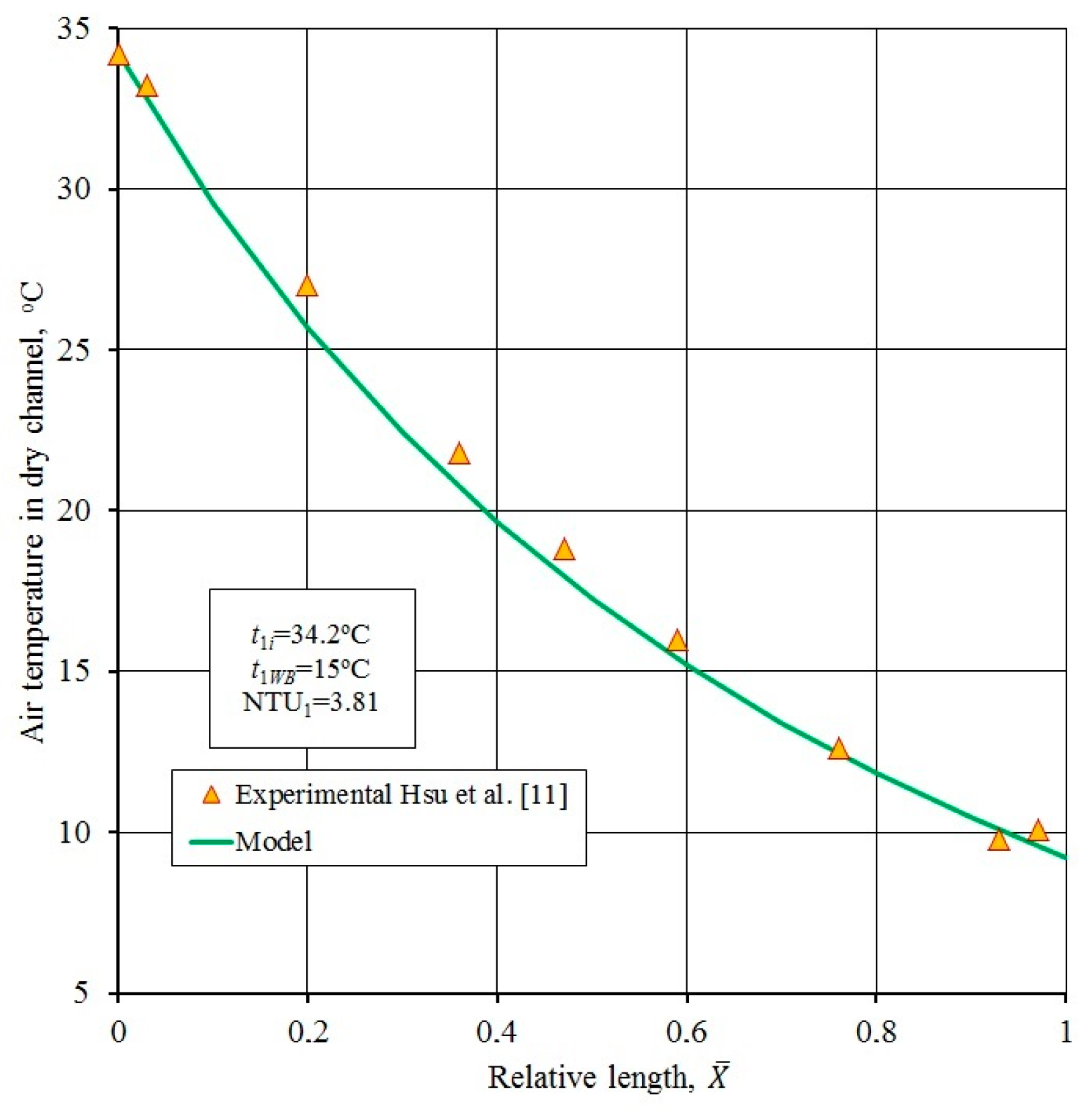
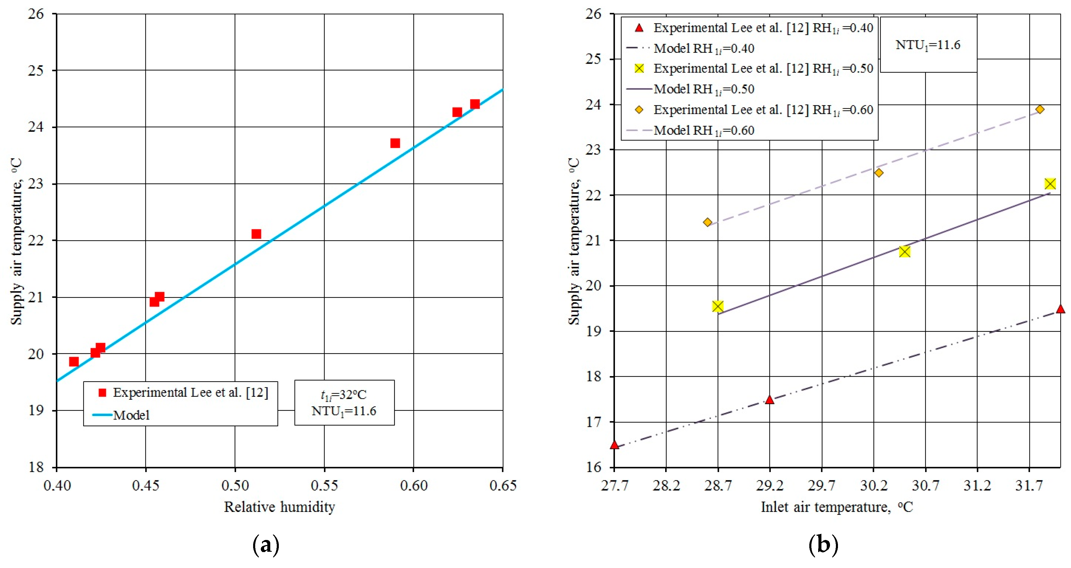
    t f i n 1 | = t p 1 = t p 1 Z ¯ 1 = 0   ; d t f i n 1 / d Z ¯ 1 | = 0   Z ¯ 1 = 1.0
The model is also supplemented by a non-linear empirical relationship between the saturation pressure of water vapor and its temperature [5]. Moreover, during calculation of the differential equations describing the heat and mass transfer in perforated HMX, the effect of mixing which makes the primary and secondary mass flow rates variable is taken into account. Therefore, mathematical model is supplemented with an additional algorithm, describing the process of the air streams mixing in the perforated HMX (such algorithm is explained in detail in [5]). The model described above is implemented in a multi-module computer simulation program to predict the thermal performance. A four-dimensional computational numerical code on the base of the modified Runge-Kutta method was implemented using the Pascal computing language.

2.2. Validation

The models were validated using existing experimental data. Measurement conditions were accurately reproduced in the numerical simulations. Authors of the experiments used for validation of the models provided a detail description of the exchangers used. The geometry of the unit (i.e., dimensions and channel characteristics) allows to calculate convective heat transfer coefficient α and heat and mass transfer surface F. Authors also provided air velocities, which allowed to calculate the mass flow rate G. These three parameters allowed calculating the NTU number. Other needed parameters, i.e., initial conditions (inlet air temperature and humidity) were also provided. Above-mentioned information was implemented in the models and this allowed performing the simulation. Mathematical models validated describe regenerative HMX. The accuracy of the mathematical model predictions are recognized to be analogous for other HMXs studied in this paper, since the numerical models describing heat and mass transfer in the investigated units are similar to ones describing other above-mentioned devices. Detail description of validation of models describing indirect evaporative air coolers performed by authors can be found in [2,3,4,5,7,8,10].
Hsu et al. [11] performed an experimental study on a counter flow regenerative heat and mass exchanger and determined the primary air temperature distribution along the dry channels. The inlet air temperature was 34.2 °C and wet-bulb temperature was 15 °C. The comparison of experimental results with calculations is shown in Figure 5. It should be noticed that the mathematical model is able to predict the distribution of temperature inside channel with satisfactory accuracy (average discrepancy about 5%).
In addition, Joohyun Lee and Dae-Young Lee [12] carried out the studies a counter-flow regenerative evaporative cooler with finned channels. The counter-flow regenerative evaporative cooler was characterized with 1.5 mm × 9.8 mm finned channels (specification in Table 2). They used a specially developed finned channel and hydrophilic porous coatings on a wet-channel to improve heat and mass transfer. The flow rate of the supply air and flow rate of the extraction air was measured by a turbine flow meter. Humidity ratio at the product air side was measured by a dew-point hygrometer. All measured data were recorded every 10 s.
The impact of inlet air conditions, water and air flow rates, and working air to primary air ratio on supply air temperature were tested experimentally. The model was set to the same operating conditions as for the experimental cases, including the exchanger geometry and inlet airflow conditions.
The indirect evaporative exchanger was examined under different inlet operating conditions while the air velocity in the dry channel was constant and equal 1 m/s. The validation of the numerical calculation is presented in Figure 6 with maximum deviation of 3.8%. The experimental work shown that under the inlet condition of 32 °C and 40% RH (relative humidity), the supply air temperature was 19.5 °C, the model predicted 19.44 °C (deviation 0.56%) (Figure 6b).

3. Results and Discussion

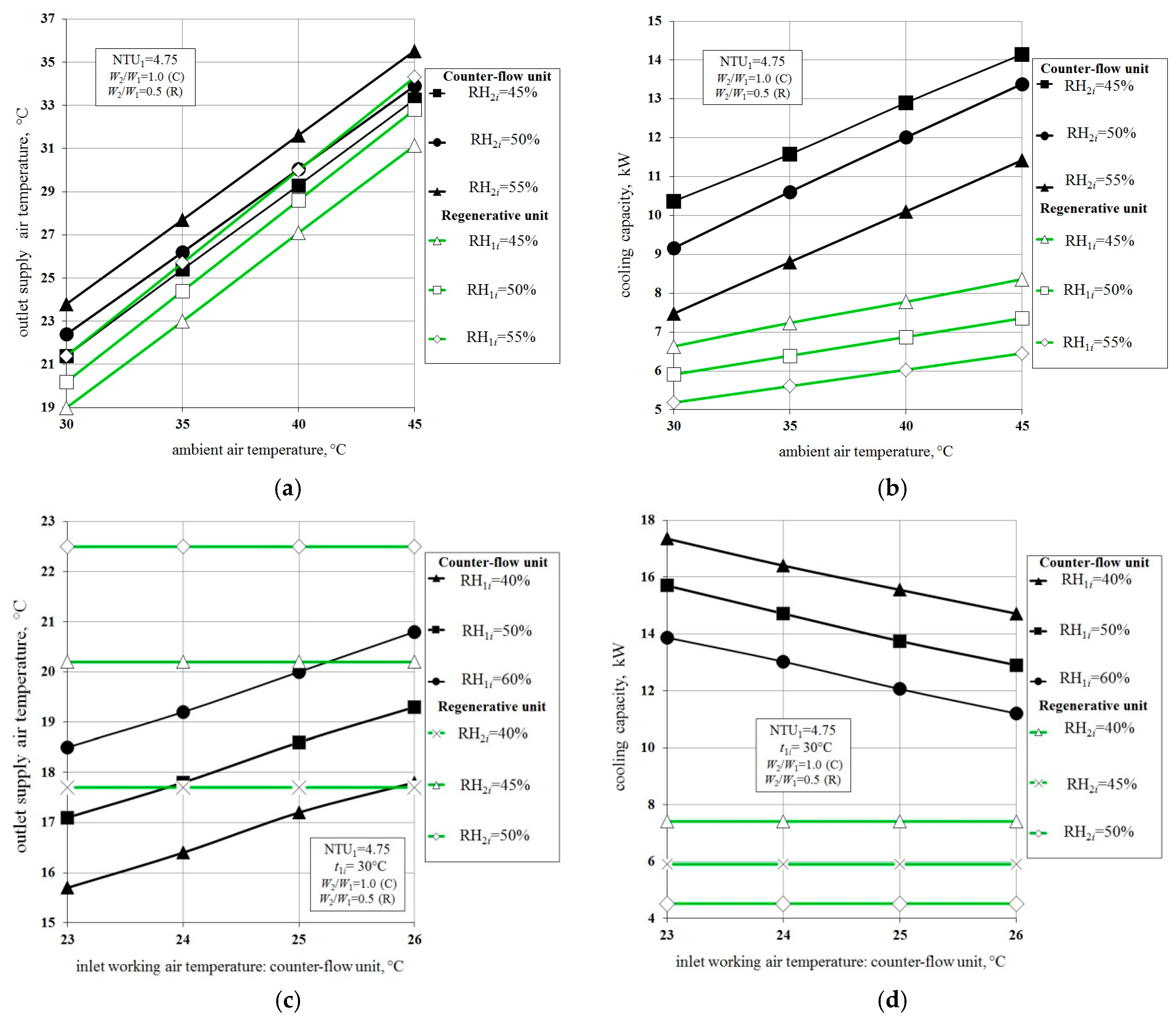
3.1. Comparision of Different Types of Evaporate Air Coolers

The comparison between the regenerative and the counter-flow units are presented in Figure 7a–d. Figure 7a shows the comparison when both units operate using only ambient air.
It is clearly shown that the regenerative air cooler is characterized by higher temperature effectiveness than the counter-flow unit. The differences are up to 1.5 °C. This is caused by the initial pre-cooling of the working airflow in the dry channel of the regenerative exchanger: if one evaporative exchanger has a hot air entering both channels, while the other has pre-cooled air with the same humidity ratio entering the wet channel, the second would obtain the lower supply air temperature. The regenerative air cooler obtains lower cooling capacity than the counter-flow cooler (Figure 7b). This follows from the flow arrangement inside the exchanger: even though it allows obtaining high temperature effectiveness by pre-cooling of the airflow, it requires a part of main air flow to be delivered to the wet channel. The counter-flow exchanger obtains a higher cooling capacity despite the fact that it is characterized by the lower temperature effectiveness. Figure 7c shows the comparison between the same exchangers, but in this case the counter-flow unit operates with exhaust airflow delivered to the wet channels (instead of outdoor air: see Figure 1c). In such an arrangement, the evaporative air cooler can operate as a pre-cooling unit for a standard cooling coil. This arrangement makes the system less sensitive to the outdoor conditions. The main advantages of the system with the counter-flow exchanger and the cooling coil is the lower sensitivity on the outlet conditions, possibility the precise regulation of the inlet temperature and humidity (cooling coil operating in drying mode) and recovery of the “free” cooling energy provided by the exhaust air. Furthermore, the indirect evaporative air cooler can also operate as a typical heat recovery unit during the winter season. The main disadvantages are: using a mechanical vapor compression system as a backup cooling source (even if its energy consumption is significantly lower) and sensitivity on the exhaust air parameters. From Figure 7 it can be observed that, depending on the ambient and exhaust air parameters, both regenerative and counter-flow units are alternately more effective. For this reasons the authors have proposed the novel solution: modified counter-flow exchanger. This device has all the advantages of the presented exchangers: depending on the indoor and outdoor conditions and it operates either as a counter-flow or regenerative air cooler.
The comparison of presented unit with other systems is shown is in Figure 8.
Figure 8a shows the comparison of the outlet supply air temperatures obtained by the novel unit and a typical counter-flow exchanger using exhaust air. It can be seen that in all cases, the modified exchanger is able to achieve lower outlet temperatures, with differences are up to 1.2 °C. The comparison of the outlet temperatures obtained by the novel device with regenerative exchanger is shown in Figure 8b. It can be observed that even for unfavorable indoor conditions (i.e., higher temperature and humidity levels) the modified unit is able to achieve similar or higher effectiveness than the air-cooled exchanger. Figure 8c shows comparison of novel unit with the regenerative exchanger with the same value of returned airflow (i.e., 20% of the main air stream). It can be seen that under such operating conditions, the modified counter-flow exchanger obtains significantly lower outlet temperatures than the regenerative unit, with differences up to 5 °C. This shows the high potential of the novel exchanger, where it is able to achieve higher thermal effectiveness due to the favorable combination of keeping the higher heat capacity of the working airflow and reduction of exhaust air humidity ratio by mixing it with dryer supply air. Due to the fact that only 20% of the airflow is returned to the wet channel, the unit is able to achieve much higher cooling capacities than the regenerative exchanger (Figure 8d). It can be seen that novel exchanger obtains a little lower cooling capacity than the counter-flow unit (the differences are up to 3 kW per every m3/s of main airflow), however it still is able to obtain over two times higher cooling capacity than the regenerative unit. Another solution, which needs to be compared with the presented unit is a regenerative heat exchanger coupled with a desiccant wheel (Figure 8f). In such systems, the airflow is dried (and also heated) by the desiccant rotor before it is delivered to the indirect evaporative cooler. Dryer air is produced by the evaporative cooling process with higher effectiveness. Such system is also less sensitive to the ambient air conditions. However, it can be observed from Figure 8f, the ambient air has to be dried to a very low humidity ratio level (which corresponds to the relative humidity of the processed air equal to 10%) to be able to achieve higher effectiveness than the novel unit. Such low humidity ratio levels require additional power for regeneration of the sorbent in the desiccant wheel. Some novel systems have tried to cover the required power with solar energy [13]. However solar systems are also dependent on the ambient conditions and usually the system requires an additional heater [14]. Moreover, the SDEC (i.e., solar descant evaporative cooling) system is more expensive and also more complicated due to the additional solar system and complicated airflow scheme. It can be seen that presented solution is able to achieve a high temperature effectiveness and cooling capacity and its sensitivity to ambient conditions is low. It is easy to implement in classical air handling units, due to the fact that it can operate in supply-exhaust air flow scheme. The main disadvantage of the presented exchanger is the fact that it still requires traditional mechanical vapor compression systems as supplementary cooling source. However, due to its adjustability it is able to significantly reduce the vapor compression system operation time. This shows that when object is not equipped with a source of the waste heat or does not have the space for solar panels, which can provide enough power for the regeneration of the desiccant wheel should rather consider systems with the novel cooler or counter-flow unit and cooling coil. If the object has the source of waste heat, the presented solution can also be considered, because it can be used to supply the absorbent chiller instead of the mechanical compression unit, which can minimize the energy consumed by the system and make it much more effective and keep it simple and inexpensive in terms of investment.

3.2. Annual Opeartion

The counter-flow unit operating as a heat recovery exchanger was selected to analyze the problems connected with annual operation of indirect evaporative coolers. The evaporative heat exchanger would operate as follows: during summer conditions, when cooling of the outdoor air is required, the return air channel is wetted with water and it operates as an indirect evaporative air cooler. When ambient temperatures become low and heating of the outdoor airflow is required, the control valve stops delivering water to the unit and the return air channel remains dry. The water left in tank is removed to the sewerage. This allows the presented unit to operate as a typical heat recovery exchanger.

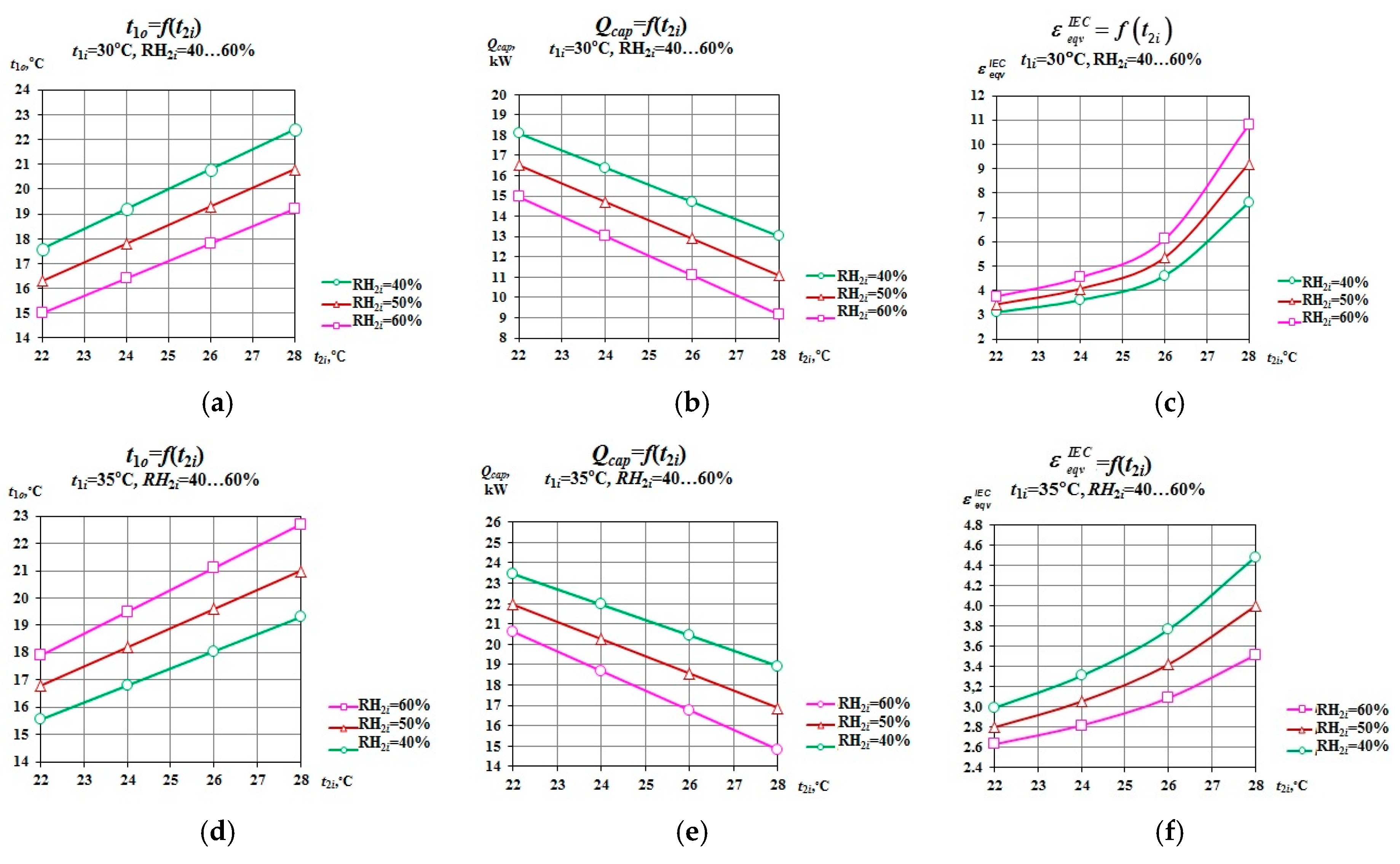
3.2.1. Cooling Effectiveness during Summer Operation

One additional factor was chosen to analyse operation in summer season:
ε e q v I E C = ( t 1 i t 1 o ) / [ ε t × ( t 1 i t 2 i ) ]
Equivalent effectiveness defined as a ratio of temperature difference between inlet and outlet outdoor airflow obtained by the considered exchanger to the difference obtained by the typical counter-flow heat recovery exchanger (no water in the exhaust air channel, only sensible heat transfer) with known temperature effectiveness (the assumed temperature effectiveness of the typical unit is equal to 0.7 [15]).
The results are presented in Figure 9. It can be seen that the efficiency of the exchanger strongly depends on the return air parameters (temperature and relative humidity). For the most favourable conditions (lowest inlet return air temperature and relative humidity), the considered exchanger achieves outlet supply air temperature equal 15.1 °C (Figure 9a), which corresponds to over 18 kW of almost free cooling power (the costs of water consumption and additional fan power are negligible comparing to the cost of the electricity consumed by typical refrigeration units [16]. For less favourable conditions (t2i = 28 °C, RH2i = 60%), the presented unit achieves supply air temperature equal 22.5 °C, which corresponds to the cooling capacity equal 9.0 kW (Figure 8b). It is clearly visible that such a low level of supply air temperatures is impossible to obtain with the standard heat recovery exchanger (standard recuperator with effectiveness equal 1.0, which is impossible to obtain in practice, is able to cool the ambient air to the inlet temperature of the return airflow). An indirect evaporative air cooler, however, is able to achieve significantly lower temperatures than the inlet temperature of the return air, due to the additional advantage of water evaporating on the plate surface in exhaust air channel. The sensible heat transferred from the outdoor airflow is not only used on heating the exhaust air, as it is in the standard heat recovery units, but it is also used on evaporation of the water. It can be seen from the equivalent efficiency factor that the presented heat exchanger is much more efficient than the typical counter-flow recuperator (Figure 9c). The differences between effectiveness obtained by the analyzed device and the typical heat recovery unit are increasing with decreasing difference between inlet temperatures of the outdoor and return airflow. The indirect evaporative air cooler, however, is able to achieve very low temperatures even when exhaust air is relatively humid and hot. It can be seen that the inlet outdoor air temperature also affects the efficiency of presented indirect evaporative air cooler (Figure 9d–f). However, for inlet outdoor air temperatures higher than 5 °C in the case presented in Figure 9a–c the obtained supply air temperatures are only 1 °C higher (Figure 9d). This is caused by the fact that return air temperature in the presented system is less dependent on the outdoor air, but on the assumed indoor conditions, which are rather constant in summer season. The cooling capacity in presented case increases by about 5 kW (Figure 9e). It can be observed that equivalent effectiveness is a little lower than in Figure 9c. This follows from the fact that temperature difference between outdoor and indoor air is higher and typical unit is able to cool ambient air more effectively (Figure 9f). However, presented exchanger is still characterized by significantly higher efficiency. It is clearly visible that application of indirect evaporative air cooling technique in heat recovery units in air conditioning systems would result in important energy savings.

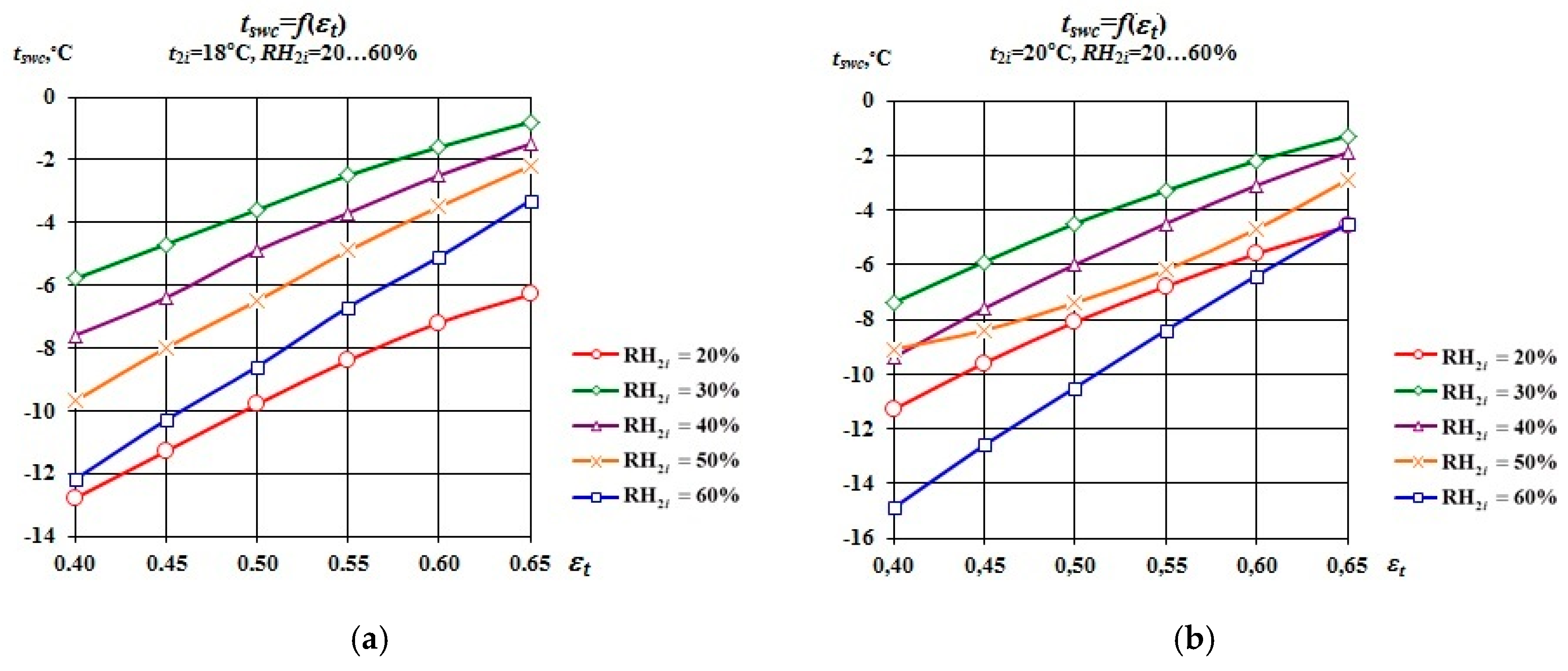
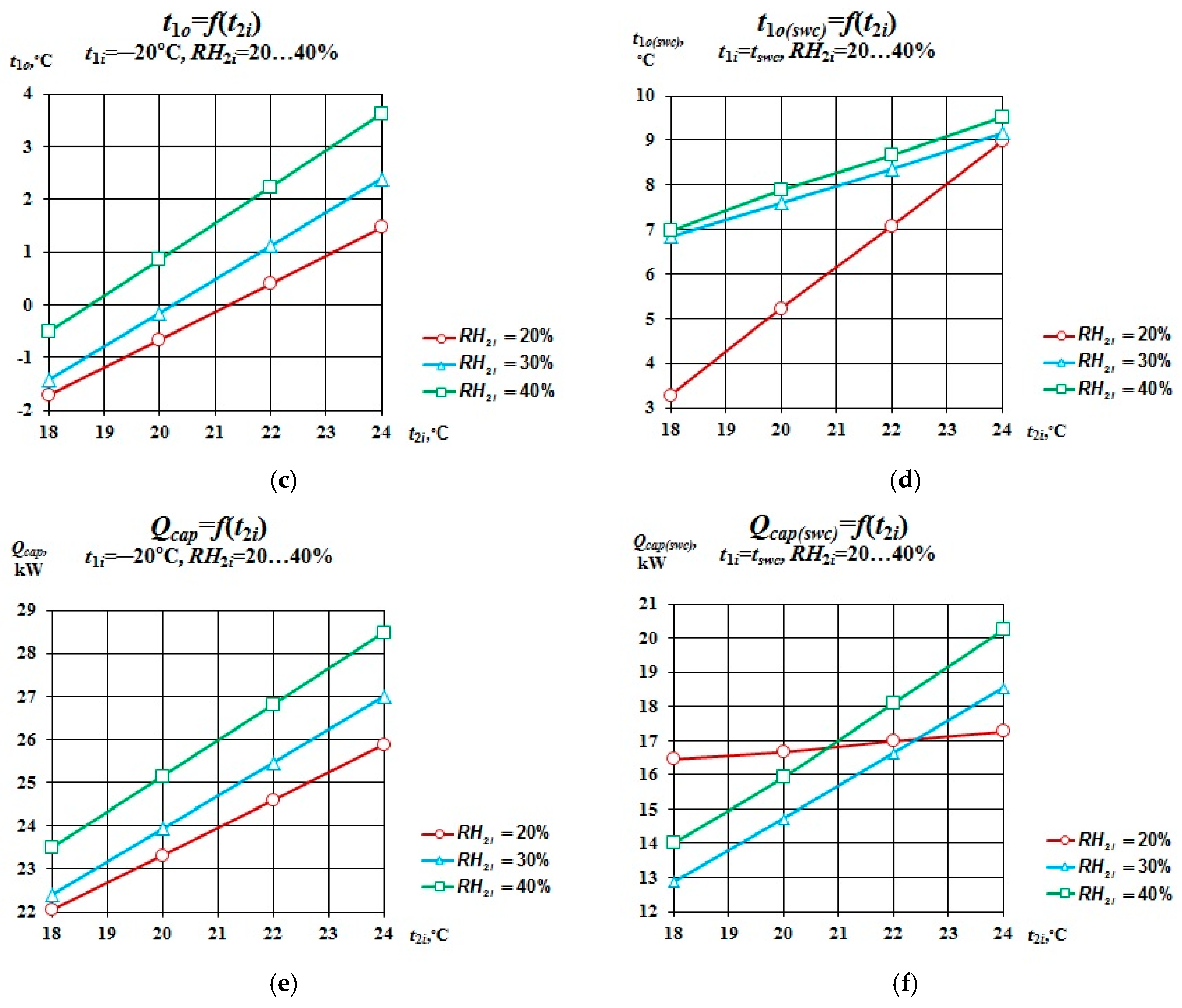
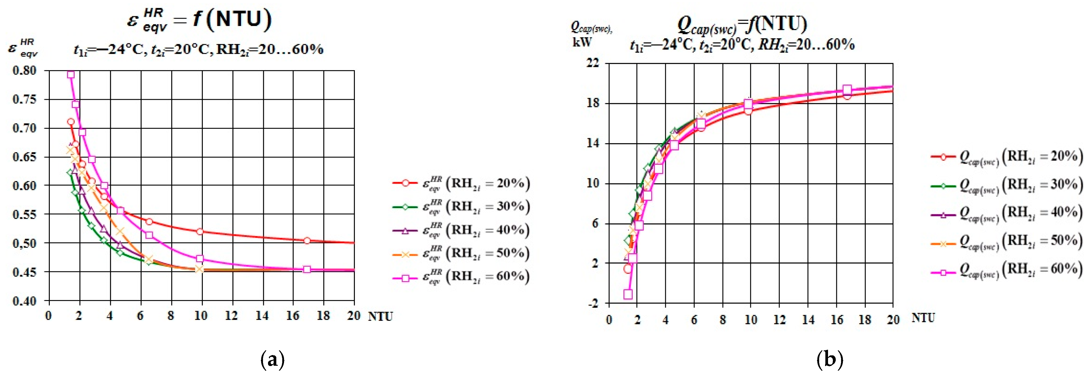
3.2.2. Heat Recovery Effectiveness and Safe Working Conditions during Winter Operation

During the winter season, the considered exchanger operates in completely different conditions, therefore other efficiency factors need to be established for its analysis. It should be mentioned that safe operation is the priority in the winter season. Operation during winter conditions is connected with risks for any type of recuperator: when outdoor temperatures are very low, the frost can condensate on the plate surface of the heat exchanger (detail information about frost formation in recuperators in winter season can be found in [16]). Frost on the plates can result in a decrease in the exchanger’s efficiency and it can eventually damage the plates. Safe working conditions (i.e., lowest outdoor temperature which allows to avoid the frost formation under exhaust air temperature with known parameters [16]) depend on three main factors: temperature efficiency of the exchanger, return air temperature and return air relative humidity. There are two important efficiency factors which are included for the analysis of the winter operation, in particular:
Temperature effectiveness:
ε t = ( t 1 i t 1 o ) / ( t 1 i t 2 i )
Equivalent effectiveness defined as a ratio of temperature difference between safe operating conditions temperature at entrance to the exchanger and outlet airflow temperature obtained for safe operating conditions at winter season to the difference at outdoor air temperature at entrance to the exchanger and outlet airflow temperature obtained at this conditions. The effectiveness is calculated under the same temperature efficiency of the exchanger (εt = const).
ε e q v H R = ( t 1 i ( s w c ) t 1 o ( s w c ) ) / ( t 1 i t 1 o )
It can be seen that safe working conditions depend on three main factors: temperature efficiency of the exchanger, return air temperature and return air relative humidity (Figure 10). Achieving higher temperature effectiveness during the winter season is connected with increasing safe temperature (Figure 10a,b). It is also visible that airflow with very low relative humidity (RH2i = 20%) allows for safe operation at very low outlet temperatures (from −12.5 to −4.2 °C, depending on the temperature of the exhaust air stream-Figure 10a,b). However, for a little higher inlet relative humidity, which corresponds to the comfortable conditions during winter (RH2i = 30% and 40% [16]), the safe temperature significantly increases. For the high level of inlet humidity (RH2i = 50% and 60% [16]) tswc index becomes low again. An explanation of this paradoxical trend is that the intensive condensation process in the form of water film at the inlet area of the return air channel causes the increase of the plate temperature at the expanse of latent heat of water-vapour condensation. Under such conditions the temperature of the exhaust airflow at the exit area of the channel is higher than in the case of realization of the “dry” (sensible) heat exchange at the initial part of the return air channel. The closer dew point temperature of the return air is to 0 °C the higher safe operating temperature is required to prevent the ice formation. For airflow with inlet temperature 20.0 °C, relative humidity which results in 0 °C dew point temperature is equal to 26.1% [16]. For airflows with lower humidity, the dew point temperature is lower than 0 °C, therefore outdoor air temperatures which cause ice formation are lower. It can be easily seen that inlet relative humidity equal 30% is very close to 26.1%, therefore the exchanger operating under such conditions requires higher safe operating temperature. This is unfortunate, since RH = 30% is usually assumed as comfortable for humans during winter season. It can be seen that safe working conditions affect the total effectiveness of the exchanger (Figure 10c–f). Although the obtained outlet temperature is higher than in case when outdoor air is not pre-heated (Figure 10c,d), the obtained heating capacity is significantly lower (Figure 10e,f). This is caused by the lower temperature difference between inlet and outlet outdoor airflow. The outlet temperatures obtained by considered exchanger are visible in Figure 10c,d. It can be concluded that safe operation of the counter-flow exchanger during winter season has direct impact on the total energy used by the system. Such exchanger requires additional heating power for its safe operation. Furthermore, its efficiency is reduced due to the lower temperature difference between return air and outdoor air after heating. This shows that precise determination of the safe working temperature is essential for the energy savings- when assumed safe temperature is too low, the exchanger will be frozen and ventilation system has to be shut down. When the assumed temperature is set to high system consumes additional rate of energy.

3.2.3. Problems Associated with Round-Year Operation

The analysis of the previous section brings important conclusion: the high efficiency of the exchanger can lead to the additional energy consumption connected with providing safe operating conditions during winter season. On the other hand, in summer time high efficiency of the considered unit is well required and it is not connected with additional costs. This problem requires a detail analysis, since the basic purpose of the heat recovery exchangers is to generate energy savings at highest level. The solution to the above-mentioned problem depends on the climate region, where such exchanger is applied. Systems operating in warmer regions (such as southern parts of Europe) are characterized with high cooling demand and low heating demand. The temperatures during the winter season in such climate conditions are usually above 0 °C. In this case, considered exchanger should guarantee maximal cooling efficiency and NTU value should be close to 6. In cold regions, such as northern Europe, the cooling demand during summer time is rather low and exchanger should guarantee highest heat recovery and safe operation during winter season. However, the NTU value for such exchanger cannot be determined generally, because it depends on the climate region, parameters of the exhaust air and source of heating energy for pre-heating of the outdoor airflow. It can be also seen that even though equivalent efficiency of the exchanger decreases with increasing NTU (Figure 11a), the exchanger can produce more heating power (Figure 11b), due to the more effective heat recovery. This problem is even more complicated in the regions with temperate climate, where cooling demand in summer and heating demand in winter are similar. This problem can only be solved with compromise optimization method applied individually to each air-conditioning system [4]. The size and type of the exchanger is determined on the basis of main source of heating and cooling power, outdoor and indoor conditions and fuel prices. Even when NTU value for heat recovery exchanger may not be optimal for indirect evaporative cooling, application of such process can lead to significant energy savings during summer time and therefore it should be considered in all heat recovery exchangers operating in air conditioning systems.

4. Conclusions

The regenerative unit is able to achieve the lowest outlet temperatures; however, it is characterized with the lowest cooling capacity. The counter-flow unit can achieve similar efficiency when it is operating as a heat recovery unit in supply-exhaust system with cooling coil. The evaporative cooling process runs with higher effectiveness due to the low temperature of the exhaust airflow. The novel counter-flow unit is a compromise between a regenerative exchanger and a counter-flow unit. It is able to achieve very low outlet temperatures, similar to the regenerative unit while keeping relatively high cooling capacity, like typical counter-flow heat and mass exchanger. Its main advantage is its ability to be adjusted: the control system in air handling unit is able to change the value of returned airflow with damper. The unit can operate as a typical counter-flow or more like regenerative exchanger depending on the outdoor conditions. This allows reduction in the energy consumed by the air conditioning system equipped with an indirect evaporative air cooler and classical cooling coil to the lowest level. The additional advantage of the presented unit is the ability to operate as a heat recovery exchanger during winter season. The study shows the high potential for the application of the novel device to air-conditioning systems.

Acknowledgments

Corresponding author (Demis Pandelidis) received financial support for his research from National Science Center Poland under the PhD scholarship based on the decision no. DEC-2015/161/T1/ST8/00484 and from resources for scientific work for years 2016-2019 from Polish Ministry of Science and High Education (program “Iuventus Plus”) Project number IP2015 058274 and from Foundation for Polish Science- FNP (scholarship Start). One of the co-authors, Paweł Drąg, received financial support in the framework of “Młoda Kadra”-“Young Staff” 0402/0228/16at Wrocław University of Science and Technology.

Author Contributions

Demis Pandelidis co-created the models, co-created the programs, performed simulations, analyzed the data and wrote the paper. Sergey Anisimov co-created the models and co-created the programs. Paweł Drąg analyzed part of the data and co-wrote the paper.

Conflicts of Interest

The authors declare no conflict of interest. The founding sponsors had no role in the design of the study; in the collection, analyses, or interpretation of data; in the writing of the manuscript, and in the decision to publish the results.

Nomenclature

cpJ/(kg K)Specific heat capacity of moist air
cgJ/(kg K)Specific heat capacity of water vapor
C-Counter-flow exchanger
E-Exhaust airflow
Fm2Surface area
hmHeight
HR-Heat recovery exchanger
Gkg/sMoist air mass flow rate
IEC-Indirect evaporative cooler
L, lmStreamwise length of cooler
M-Novel (Modified) counter-flow exchanger
M ˙ kg/sWater vapor mass flow rate (referenced to the elementary plate surface)
qW/m2Heat flux
Q c a p kWCooling capacity respected to airflow rate equal 1 m3/s Q c a p = (1 − W2/W1)·V·ρ·cp·(t1it1o), kW, where V is volumetric airflow rate equal 1 m3/s; and (1 − W2/W1) is correction coefficient including uneven values of the intake air and primary air delivered to the occupants in case of regenerative exchanger and the novel, modified exchanger (in case of the C unit it is not included)
rokJ/kgSpecific heat of water evaporation
QWRate of heat transfer
R-Regenerative exchanger
RH%Relative humidity
smFin pitch
t°CTemperature
t ¯ °CAverage temperature
vm/sAir stream velocity
Vm3/sVolumetric airflow rate
WW/KHeat capacity rate of the fluid
xkg/kgHumidity ratio
XmCoordinate along supply air flow direction
YmCoordinate perpendicular to X coordinate
ZmCoordinate along fins direction
Special characters:
αW/(m2 K)Convective heat transfer coefficient
βkg/(m2 s)Mass transfer coefficient
δmThickness
ε-Effectiveness
εeqv-Equivalent effectiveness
εt-Temperature effectiveness
ρkg/m3Density
σ-Surface wettability factor, σ∈(0.0 1.0)
Non dimensional coordinates:
Le-Lewis factor Le = α/(βc_p)
NTU-Number of transfer units Le = α/(βc_p)
X ¯ - X ¯ = X/lX—relative X coordinate
Y ¯ - Y ¯ = Y/lY—relative Y coordinate
Z ¯ - Z ¯ = Z/hfin—relative Z coordinate
Subscripts/Superscripts:
1 Main (supply) airflow
2Working airflow in the wet channels
condThermal conductivity
EExhaust airflow
finReferenced to the fins
iInlet
lLatent heat flow
metMetal foil (impenetrable cover of the plate)
oOutlet
pReferenced to the plate surface
pltReferenced to the channel plate
sSensible heat flux
swcSafe working conditions
wWater film
WBWet-bulb temperature
XAir streamwise in the dry channel
YAir streamwise in the wet channel
Conditions at the air/water interface temperature
Referenced to the plate surface
Referenced to the elementary surface

References

  1. Rogdakis, E.D.; Koronaki, I.P.; Tertipis, D.N. Experimental and computational evaluation of a Maisotsenko evaporative cooler at Greek climate. Energy Build. 2014, 70, 497–506. [Google Scholar] [CrossRef]
  2. Pandelidis, D.; Anisimov, S.; Worek, W.M. Performance study of the Maisotsenko Cycle heat exchangers in different air-conditioning applications. Int. J. Heat Mass Transf. 2015, 81, 207–221. [Google Scholar] [CrossRef]
  3. Pandelidis, D.; Anisimov, S. Numerical analysis of the heat and mass transfer processes in selected M-Cycle heat exchangers for the dew point evaporative cooling. Energy Convers. Manag. 2015, 90, 62–83. [Google Scholar] [CrossRef]
  4. Anisimov, S.; Pandelidis, D. Theoretical study of the basic cycles for indirect evaporative air cooling. Int. J. Heat Mass Transf. 2015, 84, 974–989. [Google Scholar] [CrossRef]
  5. Pandelidis, D.; Anisimov, S.; Worek, W.M. Comparison study of the counter-flow regenerative evaporative heat exchangers with numerical methods. Appl. Therm. Eng. 2015, 84, 211–224. [Google Scholar] [CrossRef]
  6. Miyazaki, T.; Akisawa, A.; Nikai, I. The cooling performance of a building integrated evaporative cooling system driven by solar energy. Energy Build. 2011, 43, 2211–2218. [Google Scholar] [CrossRef]
  7. Anisimov, S.; Jedlikowski, A. An influence of surface cross-flow plate–fin heat exchangers on efficiency of heat recovery units used in ventilation and air conditioning systems. In Proceedings of the XIIth International Scientific Conference on Quality of Indoor Air and Environment, Haifa, Israel, 23 March–3 April 2013; pp. 141–147. [Google Scholar]
  8. Pandelidis, D.; Anisimov, S. Numerical analysis of the selected operational and geometrical aspects of the M-Cycle heat and mass exchanger. Energy Build. 2015, 87, 413–424. [Google Scholar] [CrossRef]
  9. Danielewicz, J. The ecological and economic effects of thermal upgrading of buildings—The case of selected hospitals in Poland. Pol. J. Environ. Stud. 2007, 16, 90–92. [Google Scholar]
  10. Anisimov, S.; Pandelidis, D.; Danielewicz, J. Numerical analysis of selected evaporative exchangers with the Maisotsenko Cycle. Energy Convers. Manag. 2014, 88, 426–441. [Google Scholar] [CrossRef]
  11. Hsu, S.T.; Lavan, Z.; Worek, W.M. Optimization of wet-surface heat exchangers. Energy 1989, 14, 757–770. [Google Scholar] [CrossRef]
  12. Lee, J.; Lee, D.-Y. Experimental study of a counter flow regenerative evaporative cooler with finned channels. Int. J. Heat Mass Transf. 2013, 65, 173–179. [Google Scholar] [CrossRef]
  13. Alizadeh, S. Performance of a solar liquid desiccant air conditioner—An experimental and theoretical approach. Sol. Energy 2008, 82, 563–572. [Google Scholar] [CrossRef]
  14. Miyazaki, T.; Nikai, I.; Akisawa, A. Simulation analysis of open cycle adsorption air conditioning system—Numeral modeling of a fixed bed dehumidification unit and the Maisotsenko cycle cooling unit. Int. J. Energy Clean Environ. 2011, 12, 341–354. [Google Scholar] [CrossRef]
  15. Anisimov, S.; Jedlikowski, A.; Pandelidis, D. Frost formation in the cross-flow plate heat exchanger for energy recovery. Int. J. Heat Mass Transf. 2015, 90, 201–217. [Google Scholar] [CrossRef]
  16. Duan, Z.; Changhong, Z.; Zhang, X.; Mustafa, M.; Zhao, X.; Alimohammadisagvand, B.; Hasan, A. Indirect evaporative cooling: Past, present and future potentials. Renew. Sustain. Energy Rev. 2012, 16, 6823–6850. [Google Scholar] [CrossRef]
Figure 1. Counter-flow indirect evaporative air coolers. (a) “Classical” counter-flow exchanger; (b) regenerative exchanger; (c) counter-flow exchanger with cooling coil; (d) perforated regenerative exchanger; (e) regenerative exchanger with the desiccant wheel; and (f) novel modified counter-flow exchanger.
Energies 10 00577 g001
Figure 2. Initial conditions for considered exchangers. (a) Counter-flow exchanger; (b) regenerative exchanger; (c) perforated regenerative exchanger; and (d) novel counter-flow exchanger.
Energies 10 00577 g002
Figure 3. Energy balance for differential control volume: (a) view on the channels along the X axis; and (b) view on the channels along the Y axis.
Energies 10 00577 g003
Figure 4. Fin geometry and the boundary conditions for the fins in working and main air-flow passages.
Energies 10 00577 g004
Figure 5. Primary air temperature distribution in dry channel - comparison between modeled results and experimental data from [11].
Energies 10 00577 g005
Figure 6. Comparison between calculated results and experimental data from [12]. (a) Effect of the inlet humidity for constant inlet air temperature; and (b) effect of the inlet temperature for constant RH.
Energies 10 00577 g006
Figure 7. Comparison between the counter-flow and the regenerative exchanger. (a) Operation on ambient air- outlet air temperatures; (b) operation on ambient air- obtained cooling capacity; (c) counter-flow exchanger operating on exhaust airflow (wet channels) and ambient air (dry channels), regenerative exchanger operating only on ambient air- outlet air temperatures; and (d) counter-flow exchanger operating on exhaust airflow (wet channels) and ambient air (dry channels), regenerative exchanger operating only on ambient air- obtained cooling capacity.
Energies 10 00577 g007
Figure 8. Comparison of the novel exchanger with counter-flow and regenerative unit. (a) Comparison with the counter-flow exchanger operating on exhaust airflow; (b) Comparison with the regenerative air cooler operating on ambient air; (c) Comparison with the regenerative air cooler with the same amount of airflow returned to the wet channel; (d) cooling capacities obtained by the novel unit, counter-flow unit and a regenerative unit; (e) Switch points relative humidity at ambient air temperature equal 30 °C; and (f) Comparison with the regenerative air cooler operating with the desiccant wheel.
Energies 10 00577 g008
Figure 9. Analysis of indirect evaporative air cooler in summer season. (a) Obtained supply air temperature at t1i = 30 °C; (b) obtained cooling capacity at t1i = 30 °C; (c) obtained equivalent effectiveness at t1i = 30 °C; (d) obtained supply air temperature at t1i = 35 °C; (e) obtained cooling capacity at t1i = 35 °C; and (f) obtained equivalent effectiveness at t1i = 35 °C.
Energies 10 00577 g009
Figure 10. Analysis of heat recovery exchanger in winter season. (a) Obtained safe working temperature at t2i = 18 °C; (b) obtained safe working temperature at t2i = 20 °C; (c) obtained supply air temperature t1o at outdoor air temperature t1i = −20 °C; (d) obtained supply air temperature t1o at safe working temperature t1i = tswc; (e) obtained heating capacity at t1i = −20 °C; and (f) obtained heating capacity at t1i = tswc.
Energies 10 00577 g010aEnergies 10 00577 g010b
Figure 11. Analysis of round-year operation. (a) Equivalent effectiveness of heat recovery exchanger as function of NTU number; and (b) obtained cooling capacity by heat recovery exchanger as function of NTU number.
Energies 10 00577 g011
Table 1. Assumptions for the mathematical model.
ProblemAssumption
Heat exchange with the surroundingsAssumed as negligible
OperationSteady state
Airflow physical propertiesIdeal and incompressible gas
Water rate consumptionUsed for evaporation and for keeping the plate surface at a saturated state. Air flow heat capacity is much larger than that of the water
Driving force of mass transferHumidity ratio gradient (gradient of partial pressure of the water vapor)
Kinetic properties of air stream and waterConstant and assumed as equal to bulk average values
Other important assumptionsThe temperature of the water film, the sensible heat transfer coefficient α and the Lewis factor depend on the operating conditions [5]
Table 2. Input data and specifications for regenerative counter flow heat and mass exchanger from [12].
Input DataValuesUnit
Inlet air temperature27–32°C
Inlet relative humidity of air40–60%
Inlet air flow0.2kg/s
W2/W10.3-
Air velocity in the dry channel1.0m/s
Air velocity in the wet channel0.6m/s
NTUdry channel11.6-
NTUwet channel22.0-
External size550 × 690 × 350mm

