Abstract
Inductively coupled power transfer (ICPT) systems, which are superior to batteries due to their real-time power supplycapacity have been used in mooring buoys for the purpose of long-term measurements. A multiple-receiver ICPT system for mooring buoys, which contains a mooring cable for transmitting power, is proposed in this paper to obtain the corresponding profile parameters. Series compensation is applied to all three sections, including the transmitter, the mooring cable and multiple receivers. The voltage of an underwater system with arbitrary load can be stabilized. On that basis, high efficiency can be obtained. By adopting Wolfram Mathematica a detailed analysis of both double-receiver and multiple-receiver ICPT systems for mooring buoys is presented. Finally, a prototype ICPT system with three receivers mounted on a 30 m mooring cable was built to verify the theoretical analysis. Experimental results show that the power transfer efficiency exceeds 45%. Both theoretical analysis and experiments indicate that this system is appropriate for measuring ocean profile parameters.
1. Introduction
Covering approximately 71% of the Earth’s surface and representing 90% of the Earth’s biosphere, oceans play a major role in the world [1]. A comprehensive monitoring network is being established and mooring buoys are an important component of this. Fixed in place by a mooring cable, buoys can measure profile parameters over a long-term.
Presently the power for underwater sensors is normally provided by batteries, however, these must be replaced when they run low on power. To achieve the purpose of real-time measurement over a long-term, a single-receiver inductively coupled power transfer (ICPT) system can be used in a mooring buoy to transfer power. Power is stored in super-capacitors, and sensors can receive power from them to measure parameters, such as temperature or salinity, at a determine depth [2,3]. In order to transfer power from a buoy to underwater systems, the mooring cable acts as a transmission route. In [4], a model of a single-receiver ICPT system for mooring buoys was established, and inductor-capacitor (LC) resonant compensation was adopted in the mooring cable to reduce the influence of inductance elements. Furthermore, the ICPT system has several advantages such as it is easy to replace sensors and it is suitable for measurement. Nevertheless, it is more significant to measure the parameters of different depths using different sensors mounted on the mooring cable. Therefore, this paper focuses on a multiple-receiver ICPT system for mooring buoys.
As for ICPT systems, both modeling and compensation have been studied over the past decade [5,6,7,8]. Series- and parallel-compensation are two common methods to improve system properties such as the output power and the power transfer efficiency [9]. In addition, compensation like series-parallel and inductor-capacitor-inductor type (LCL-T) structures are widely applied in high power ICPT systems to eliminate the imaginary part of the system’s overall impedance [10,11]. Studies on different multiple-receiver models have been discussed. In [12] an energy supply system for a system with 30 devices aligned on one solid installation rail using E-shaped magnetic cores was created. The output power of each device was more than 4 W. However, the input power and the power transfer efficiency were not mentioned. Paper [13] discussed an electrical energy transmission system for multi-load scenarios. Coreless planar transformers were applied in the system to reduce core losses. This system is suitable for portable electric equipment rather than underwater devices mounted on a mooring cable. Nowadays, the applications of the multiple-receiver ICPT systems focus on cellphone charging, wearable devices and electric vehicles [14,15,16]. However, compared with those traditional ICPT systems, in this paper the ICPT system for mooring buoys adds a mooring cable, which can transfer power as well as fix the buoy. This makes it more complex to analyze multiple-receiver ICPT systems for mooring buoys.
On the other hand, lots of papers have studied the characteristics of multiple-receiver systems with the same load [17,18,19]. In order to obtain different parameters in the ocean, different sensors will be used in mooring buoy applications, and the charging status of super-capacitors will be different at the same time. Thus, the equivalent impedance of each underwater system is different, and the voltage in underwater systems will fluctuate in a large range. This may damage step-down regulators and affect the operating status of sensors. Ensuring the proper operation of underwater systems is a great challenge for a multiple-receiver system. Paper [20] reported a multiple-receiver wireless power transfer system with arbitrary load using capacitive impedance matching networks (IMNs). Due to the charging process of lithium-ion rechargeable batteries, the charging system can be considered as a variable load. Series-parallel and parallel-series networks were analyzed for charging multiple devices. However, using parallel compensation will increase the equivalent resistance of the system, which has a great influence on the voltage division.
From the aforementioned review, it is envisaged that in practical applications each receiver must have a stable voltage for different underwater systems, and on that basis, the system needs to simultaneously achieve high efficiency. In this paper, a multiple-receiver ICPT system for mooring buoys is proposed, which is designed to realize the stable voltage and high efficiency of underwater systems by using series compensation for all loops based on mathematical derivation. In addition, for the prototype ICPT system with three receivers mounted on a 30 m mooring cable, the voltage division ratio between two arbitrary receivers is almost 1, while the power transfer efficiency can exceed 45%. The system proposed in this paper can be applied for measuring profile parameters in real-time, and will provide a reference for the development of multiple-receiver ICPT systems.
The rest of this paper is organized as follows: in Section 2, a structure of the multiple-receiver ICPT system for mooring buoys is presented, and key parameters of this system are defined. In Section 3, the double-receiver system model is analyzed in detail, and then calculated by Wolfram Mathematica to achieve load-independent voltage ratio and high efficiency. In Section 4, the theoretical analysis is extended to an ICPT system for mooring buoys with receivers. In Section 5, an experimental prototype is established to verify the results of Section 4. Finally, Section 6 draws some conclusions about our findings.
2. System Structure
The composition of a multiple-receiver ICPT system for mooring buoys is shown in Figure 1a. The power is converted by solar battery boards and stored in a lead-acid battery, which can provide 12 V/150 Ah electricity. The mooring cable, which fixes the buoy in a certain area with the help of an anchor system, acts as a power transmission cable. Underwater systems, which are mounted on the mooring cable, can get power from the lead-acid battery by using the mooring cable and inductive couplers.
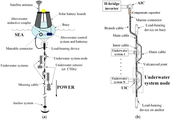
Figure 1.
The composition of a multiple-receiver ICPT system: (a) Mooring buoy; (b) Mooring cable.
Figure 1b reveals the design of the system circuit model with mooring cable. In this special ICPT system, the mooring cable can be divided into three sections: the secondary coil of the abovewater inductive coupler (AIC), the primary coil of underwater inductive couplers (UICs) and the main cable used for transmitting power between the AIC and UICs. The mooring cable is a closed cable as the branch cable is connected with the abovewater controller through the marine connector, and it is wrapped by a shielding layer. Therefore the self-inductance of the mooring cable is a constant and will not be affected by seawater ([21], pp. 7–8). It is important to calculate the resonant capacitor in the resonant state. Moreover, we have measured the self-inductance of the mooring cable in the sea at different frequencies, and compared with that in the air. The results are listed in Table 1. The number of underwater system nodes is determined by the specific application. Usually, the distance between any underwater system nodes is long (more than 3 m), and the mutual inductance between UICs can be ignored.

Table 1.
The self-inductance of mooring cable in different frequency.
An H-bridge inverter is utilized to convert the DC power generated by the battery into a high-frequency rectangular wave. Four quality field effect transistors (QFETs) FQA38N30 (Fairchild Semiconductor, San Francisco, CA, USA) constitute the H-bridge structure as shown in Figure 2a. Two complementary pulse width modulation (PWM) waves with dead band time are generated by the microcontroller unit, and the QFETs are driven through two driver chips IR2110 (Infineon, Neubiberg, Germany). Through the H-bridge inverter, the DC power can be inverted to rectangular wave with variable frequency. Based on Faraday’s law, a high frequency magnetic field is generated in the AIC, and the power is transmitted by the mooring cable. Through the vulcanized joints, the main cable is divided into inner cable and outer cable. UICs are mounted on the inner cable and underwater systems can obtain power from the mooring cable based on Faraday’s law as well. Finally, a full-bridge rectifier and a step-down regulator are applied to convert AC power to DC to charge the super-capacitors in each underwater system. Underwater sensors, such as conductivity-temperature-depth sensors (CTDs), can obtain power from super-capacitors and measure parameters at any time. Figure 2b shows the composition of the underwater system. In general, a super-capacitor charging system can be regarded as a variable load with time. Considering the influence of step-down regulators and rectifiers [22], the equivalent load resistance of underwater system is:
where is the duty-cycle of the step-down regulator, which is equal to 0.75 in this system. is the equivalent resistance of super-capacitor charging system, the range of is from 83 Ω to 434 Ω by experiments. From (1), the range of is from 120 Ω to 625 Ω.
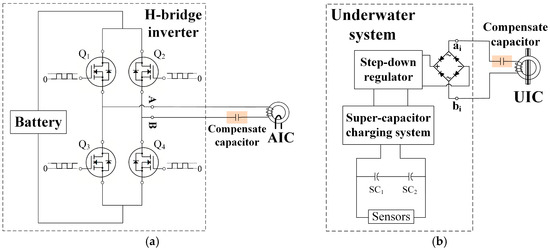
Figure 2.
Important compositions of a multiple-receiver ICPT system for mooring buoy: (a) H-bridge inverter; (b) Underwater system.
AIC and UICs have the same structure, which is shown in Figure 3. A toroidal ferrite magnetic core is cut symmetrically in order to conveniently mount on the inner cable. The parameters of the inductive coupler are listed in Table 2. Using a special sealing device, the inductive coupler is completely isolated from seawater, and the coupling coefficient is measured as 0.97.
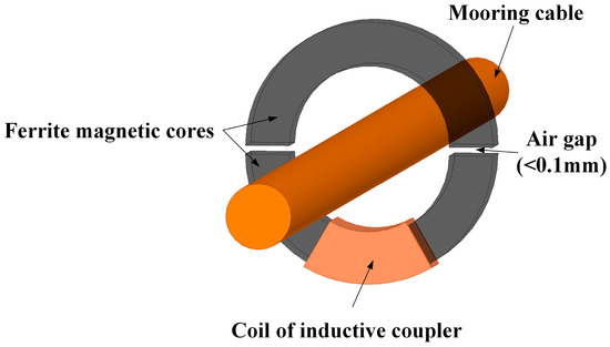
Figure 3.
The structure of the inductive coupler.
Table 2.
Parameters of the inductive coupler.
In order to analyze the multiple-receiver ICPT system for mooring buoys, definitions of some key parameters are tabulated in Table 3. The symbol is the number of receivers in the range of 1 to n.
Table 3.
Definitions of parameters.
3. Double-Receiver ICPT System for Mooring Buoy
A model of double-receiver ICPT system for mooring buoy is shown in Figure 4. It is divided into four parts: one transmitter (TX), one mooring cable, and two receivers (RX1 and RX2). Using one AIC and two UICs, TX, RX1 and RX2 are coupled to the mooring cable with mutual inductances of , and respectively. The coupling coefficient between the AIC’s coils is:
and the coupling coefficient between the UICs’ coils is:
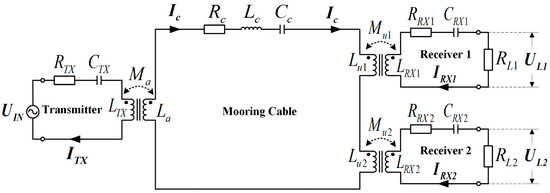
Figure 4.
Model of a double-receiver ICPT system for mooring cable.
Since the distance between two receivers is sufficiently long, the mutual inductance between RX1 and RX2 can be ignored.
In Figure 4, is the input voltage with the frequency between and shown in Figure 2a. is the angular frequency, which is equal to ; and are the voltage to the loads. , , and are the current of TX, mooring cable, RX1 and RX2 respectively; and are the gain of voltage and defined as and ; and are the active power delivered to two equivalent loads and . Finally, the power transfer efficiency can be calculated as a ratio between the total active power received by equivalent loads and the apparent power supplied by the source [23].
The equivalent impedance of each loop can be described as , where is the resistance and is the reactance. is the resistance of the coil, while the equivalent series resistance of the capacitor is ignored because it is generally small in network [24]. Using to substitute , and , the circuit’s current , and are contacted with the input voltage employing by Kirchhoff’s voltage law (KVL):
where:
3.1. Compensate for Coils Inductance of Receivers
Solving (4) gives the relationship:
In the double-receiver ICPT system for mooring buoy, the UICs are the same, including magnetic cores and coils. Therefore, the parameters of each UIC are equal:
As shown in the Figure 4 and Equation (7), the resistance , and the reactance . Normally, the resonant angular frequency and the normalized angular frequency of RX are defined as:
and, the equivalent impedance of coil in receivers:
According to the definition of and and hypothesize , the voltage division ratio between two receivers can be obtained as:
In order to achieve the load-independent voltage ratio, an appropriate operating angular frequency will be chosen.
Parameters of receivers are talented in Table 4. The voltage division ratio between two receivers , which is a function of the normalized angular frequency of RX is shown in Figure 5. On the one hand, the voltage division ratio between two receivers is close to 1 when . In other words, the operating angular frequency equals the resonant angular frequency of RX. That means the voltage to different equivalent loads in different receivers is nearly equivalent as the receiver’s coil work in the resonant state. On the other hand, the voltage division ratio between two receivers is closer to 1 as the resistance of coils decrease.
Table 4.
Parameters of receivers.
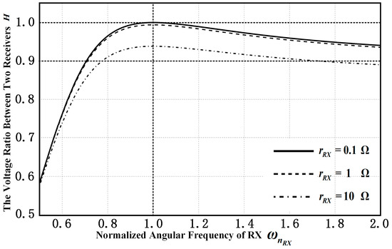
Figure 5.
The voltage ratio between two receivers versus the normalized angular frequency of RX.
3.2. Compensate for Coils Inductance of Tranmitter and Mooring Cable
Ensuring that the voltage across the equivalent load is approximately equal by compensating for coils inductance of receivers, the most important characteristic of the ICPT system for mooring buoys is promoting the output power received by underwater systems and the power transfer efficiency, which are defined as:
where means the conjugate of . Solving (4) and under the condition of , the voltage to equivalent loads are obtained as:
where:
and the output power received by underwater systems and the power transfer efficiency can be described by following equation:
It can be observed that the output power and the power transfer efficiency are related to and . As definition from (17) and (18), is a constant and is function of the reactance of coil in transmitter and of mooring cable . When the inductive couplers are determined, parameters of coils in transmitter and receivers as well as mooring cable, such as the resistances (, , , ) and the mutual inductances (,) are affirmative. and are expressed as follows:
Similarly, the resonant angular frequency and the normalized angular frequency in the transmitter and mooring cable are defined as:
and the reactance can be represented as:
According to (17)–(20), the output power and the power transfer efficiency can be written as:
where:
From (25)–(34), and are functions of two variables and as follows:
where and .
Since can be adjusted easily in the system of a mooring buoy, a suitable input voltage can be chosen according to actual demand power since . Therefore, the power transfer efficiency is attracting more attention in this situation. In order to achieve the maximum of the power transfer efficiency , the method of getting the maximum is used as follows. Solving the equations:
Using (37) to get a stationary point and obtain:
To check the point is whether the extreme point or not, the functions , and are calculated. And then obtain
Obviously, all parameters are positive, so as well as . According to the necessary and sufficient condition of maximum value of two variable function, the stationary point is the maximum point and correspondingly ([25], pp. 946–950).
Parameters of transmitter and mooring cable are tabulated in Table 5. Figure 6 is drawn to verify the maximum point. On the one hand, the relationship between the power transfer efficiency and the normalized angular frequency of mooring cable is shown in Figure 6a. For different , the can be obtained at different correspondingly. Comparing these local maximum points for each curve, the absolute maximum point can be found as and and the maximum efficiency is 60.85%. On the other hand, Figure 6b depicts the relationship between the power transfer efficiency and the normalized angular frequency of transmitter. This time, is a discrete parameter while take a continuous value from 0.5 to 2. It is clearly that the maximum obtained at and as the same of Figure 6a. Analyzing of these two graphs, efficiency has an absolute maximum at and . From (24), in that condition, and the method of getting the maximum is verified. In addition, ensuring is more important than to achieve higher efficiency by comparing these two graphs.
Table 5.
Parameters of transmitter and mooring cable.
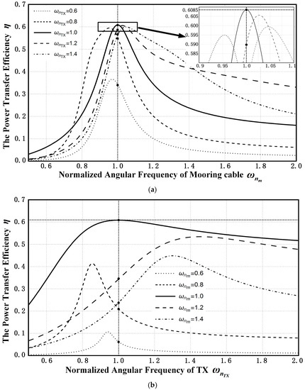
Figure 6.
The power transfer efficiency versus different normalized angular frequency: (a) Normalized angular frequency of mooring cable; (b) Normalized angular frequency of TX.
4. Multiple-Receiver ICPT System for Mooring Buoy
Here, the multiple-receiver ICPT system for a mooring buoy, which is similar to a two-receiver system, is shown as Figure 7. In this model, receivers are mounted on the mooring cable while the power is provided by one transmitter. is the equivalent load resistant in receiver , as well as and are the parameters of receiver . The mutual inductance for UICs is defined as and they are identical in order to simplified analysis, while the coupling coefficient between inductive coupler’s coils are:
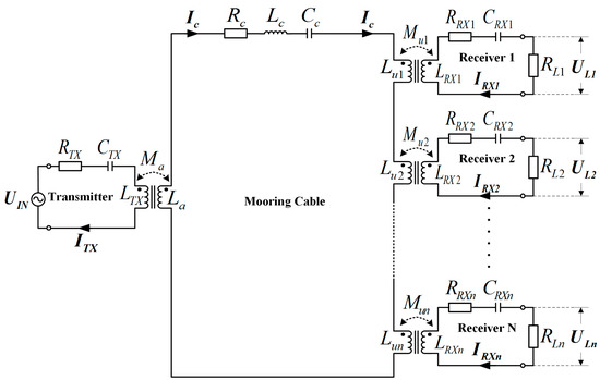
Figure 7.
Model of a multiple-receiver ICPT system for mooring cable.
The KVL is applied to multiple-receiver system to get the voltage division ratio between two arbitrary receivers, the output power and the power transfer efficiency, where and .
Similarly, ensuring identical voltage to different loads in different receivers is the first task. From (44), as , where the resistances of coils are too small to the equivalent loads. In that case, the (42) can be simplified as:
where is defined as the sum of the resistance of coils and the resistance of equivalent loads , for the range of is from 1 to . Based on (46), the voltage to equivalent loads is calculated as:
where:
And the output power and the power transfer efficiency are obtained:
Pay attention to this: when , (47)–(51) are identical with (16)–(20). From (51), is the function of and and can be described as:
where:
It is similar to (36). Based on the method of getting the maximum, circuits of the transmitter and the mooring cable are working at full resonance state, meaning and , the maximum power transfer efficiency can be obtained
Meanwhile, experiments are carried out in Section 5 for three-receivers to verify the theory of the multiple-receiver ICPT system for mooring buoys.
5. Experimental Results and Discussion
5.1. Experimental Setup
A special three-receiver ICPT system for mooring cables, shown as Figure 8, was built and tested to verify the above analysis. One AIC and three UICs were mounted on a special mooring cable with a length of 30 m. The parameters of this system were measured by an inductance-capacitance-resistance (LCR) tester and listed in Table 6. A DC power supply, which can provide 24 V/5 A to replace the battery in the buoy, was used as the source voltage. Since the H-bridge structure was used to provide a high frequency signal, the signal generated from the inverter was a square wave. The Fourier series of a square wave is [10]:
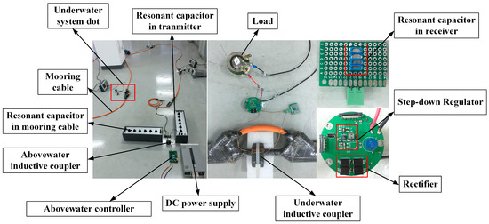
Figure 8.
Experimental setup.
Table 6.
Measured parameters of the three-receiver ICPT system for mooring buoy.
Since the amplitude decreases rapidly with increasing frequency and the system has good filtration characteristics when working in the resonant state, the fundamental frequency is considerated without other harmonic frequency signal. In this case V, where the frequency was chosen as rad/s. In applications, underwater sensors are always driven by DC power. Thus, the rectifier and the step-down regulator were used to convert high frequency signal from UIC’s secondary coil to DC power, in the following paper is the equivalent load of super-capacitor charging system. The relationship of and the equivalent load of underwater system is shown in Equation (1).
Waveforms of voltage to underwater systems were observed by oscilloscopes, and the current in the mooring cable was measured by a current probe. To calculate the power transfer efficiency, wattmeters were used to measure the power of super-capacitor charging system . The input power of the overall system can be calculated by the voltage and current, which were displayed on the DC power supply.
5.2. Results and Discussion
Figure 9 shows the relationship between the voltage division ratio and the equivalent load of the super-capacitor charging system where Ω and Ω. Since the range of is from 83 Ω to 434 Ω, when the receivers work in resonant status. On the other words, the voltage of underwater system with different equivalent loads of super-capacitor charging system can be kept steady as the above analysis.
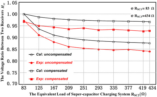
Figure 9.
The relationship between the voltage division ratio and the equivalent load of super-capacitor charging system .
Moreover, the relationship between the power transfer efficiency and the equivalent load of super-capacitor charging system is shown in Figure 10. From (53)–(57), the efficiency will be influenced when the equivalent load of super-capacitor charging system changes because of the process of super-capacitor charging. Since and were constant, the efficiency decreased from 50.3% to 42.8% with a change of the load resistance from 83 Ω to 434 Ω.
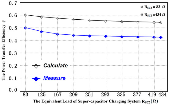
Figure 10.
The relationship between the power transfer efficiency and the equivalent load of super-capacitor charging system .
Figure 11 displays the maximum efficiency can be obtained when the transmitter and the mooring cable work in resonant status. When the operating frequency deviated from the resonant frequency, which was 20 kHz, the efficiency reduced obviously.
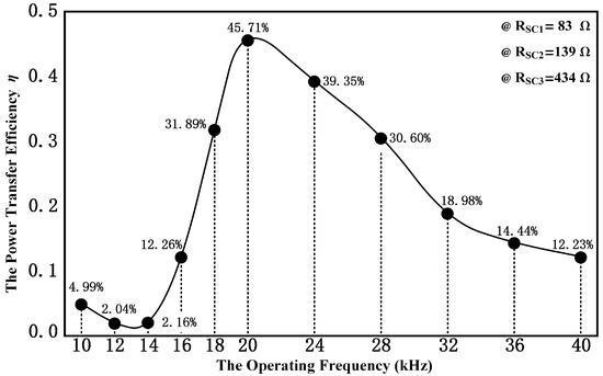
Figure 11.
The power transfer efficiency versus the operating frequency.
Finally, an intuitive phenomenon is shown in Figure 12. Waveforms of voltage to underwater systems and the current in mooring cable were measured within different three compensation: compensated receivers, compensated mooring cable and with all loops compensated. The test points of voltage are and , which are shown in Figure 2b. Table 7 summarizes the power of equivalent loads of super-capacitor charging system and the power transfer efficiency in those three conditions. Comparing with the method of compensating all loops, the power transfer efficiency was too low when receivers were compensated only, while the voltage to different equivalent loads of super-capacitor charging system were uneven when the mooring cable was compensated only. The result of this experiment verified the mentioned theory.
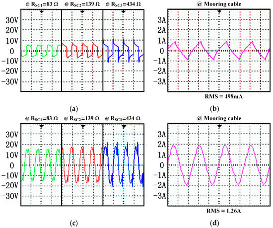
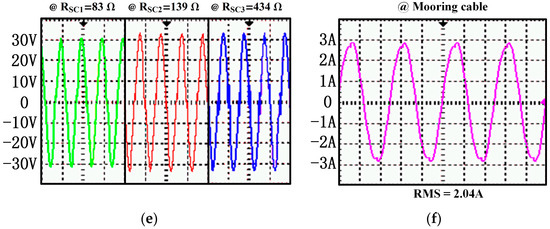
Figure 12.
Waveforms measured by oscilloscopes: (a) The waveform of voltage to underwater systems by compensating receivers; (b) The waveform of current in mooring cable by compensating receivers; (c) The waveform of voltage to underwater systems by compensating mooring cable; (d) The waveform of current in mooring cable by compensating mooring cable; (e) The waveform of voltage to underwater systems by compensating all loops; (f) The waveform of current in mooring cable by compensating all loops.
Table 7.
Experiment result for different compensation.
According to the experimental tests in this Section, the highest efficiency of the three-receiver ICPT system for mooring buoys is 45.71% while the theoretical value is 58.48% because of the filtration characteristic and losses of AC-DC converters.
6. Conclusions
A multiple-receiver ICPT system for mooring buoys was proposed in this paper. The structure of the mooring cable and inductive couplers were introduced firstly. Then, the circuit model of a two-receiver ICPT system for mooring buoys was analyzed to achieve identical voltage of underwater systems to different loads by using compensation in receivers. On that basis, higher power transfer efficiency can be obtained with compensating in the transmitter and mooring cable, since the system is working in a resonant status. Furthermore, the analysis can be extended to multiple-receiver ICPT systems. The results were validated by means of theoretical calculations and the practical experiments. Based on the research in this paper, the multiple-receiver ICPT system for mooring buoys can be applied to measure real-time profile data of oceans.
Acknowledgments
All works of this project received support as follows: State Oceanic Administration P.R.C. and the project Nos. is “cxsf2014-6” and “2014405006-3”, Tianjin Oceanic Administration and the project No. is “KJXH2012-11”, Ministry of Science and Technology, and Human Resources Department of Qingdao Oceantec Valley Core Region Administration and the project No. is “201503001”, Qingdao National Labboratory for Marine Science and Technology and the project No. is “ZR2016WH01”.
Author Contributions
Jiayi Xu calculated the model, conceived the experiments and wrote the paper; Xingfei Li conceived the project and provided guidance; Jiayi Xu and Ziming Xie designed and performed the experiment; Huilin Zhang analyzed the data; Tengfei Wu proposed key suggestions for improving this paper; Cheng Fang contributed analysis and measuring tools. All authors read and approved the manuscript.
Conflicts of Interest
The authors declare no conflict of interest.
References
- Charette, M.A.; Smith, W.H.F. The volume of earth’s ocean. Oceanography 2010, 23, 112–114. [Google Scholar] [CrossRef]
- Yoshioka, D.; Sakamoto, H.; Ishihara, Y.; Matsumoto, T.; Timischl, F. Power feeding and data-transmission system using magnetic coupling for an ocean observation mooring buoy. IEEE Trans. Magn. 2007, 37, 2663–2665. [Google Scholar] [CrossRef]
- Huang, Y.G.; Fang, C.; Li, X.F. Contactless power and data transmission for underwater sensor nodes. EURASIP J. Wirel. Commun. Netw. 2013, 2013, 81. [Google Scholar] [CrossRef]
- Fang, C.; Li, X.; Xie, Z.; Xu, J.; Xiao, L. Design and optimization of an inductively coupled power transfer system for the underwater sensors of ocean buoys. Energies 2017, 10, 84. [Google Scholar] [CrossRef]
- Boys, J.T.; Covic, G.A.; Reen, A.W.G. Stability and control of inductively coupled power transfer systems. IEE Proc. Electr. Power Appl. 2000, 147, 37–43. [Google Scholar] [CrossRef]
- Elliott, G.A.J.; Covic, G.A.; Kacprzak, D.; Boys, J.T. A new concept: Asymmetrical pick-ups for inductively coupled power transfer monorail systems. IEEE Trans. Magn. 2006, 42, 3389–3391. [Google Scholar] [CrossRef]
- Kissin, M.L.G.; Covic, G.A.; Boys, J.T. Steady-state flat-pickup loading effects in polyphase inductive power transfer systems. IEEE Trans. Ind. Electron. 2011, 58, 2274–2282. [Google Scholar] [CrossRef]
- Pantic, Z.; Bai, S.; Lukic, S.M. ZCS LCC-compensated resonant inverter for inductive-power-transfer application. IEEE Trans. Ind. Electron. 2011, 58, 3500–3510. [Google Scholar] [CrossRef]
- Zhang, W.; Wong, S.C.; Tse, C.K.; Chen, Q. Analysis and comparison of secondary series and parallel compensated inductive power transfer systems operating for optimal efficiency and load-independent voltage-transfer ratio. IEEE Trans. Power Electron. 2014, 29, 2979–2990. [Google Scholar] [CrossRef]
- Sohn, Y.H.; Bo, H.C.; Lee, E.S.; Lim, G.C. General unified analyses of two-capacitor inductive power transfer systems: Equivalence of current-source SS and SP compensations. IEEE Trans. Power Electron. 2015, 30, 6030–6045. [Google Scholar] [CrossRef]
- Esteban, B.; Sid-Ahmed, M.; Kar, N.C. A comparative study of power supply architectures in wireless EV charging systems. IEEE Trans. Power Electron. 2015, 30, 6408–6422. [Google Scholar] [CrossRef]
- Wesemann, D.; Witte, S.; Michels, J.S. Effects of multiple loads in a contactless, inductively coupled linear power transfer system. In Proceedings of the International Conference on Electrical and Electronics Engineering, Bursa, Turkey, 5–8 November 2009; pp. I-54–I-59. [Google Scholar]
- Liao, Y.H.; Hsu, C.C. A novel AC/DC bridgeless and contactless electrical energy transmission system for multi-load applications. IEEE Trans. Ind. Appl. 2016, 52, 1148–1156. [Google Scholar]
- Casanova, J.J.; Zhen, N.L.; Lin, J. A loosely coupled planar wireless power system for multiple receivers. IEEE Trans. Ind. Electron. 2009, 56, 3060–3068. [Google Scholar] [CrossRef]
- Choi, M.; Jang, T.; Jeong, J.; Jeong, S.; Blaauw, D.; Sylvester, D. A resonant current-mode wireless power receiver and battery charger with −32 dBm sensitivity for implantable systems. IEEE J. Solid-State Circuits 2016, 51, 2880–2892. [Google Scholar] [CrossRef]
- Lu, F.; Zhang, H.; Hofmann, H.; Mi, C. A dynamic charging system with reduced output power pulsation for electric vehicles. IEEE Trans. Ind. Electron. 2016, 63, 6580–6590. [Google Scholar] [CrossRef]
- Van Der Pijl, F.F.; Ferreira, J.A.; Bauer, P.; Polinder, H. Design of an inductive contactless power system for multiple users. In Proceedings of the 2006 IEEE Industry Applications Conference 41st IAS Annual Meeting, Tampa, FL, USA, 8–12 October 2006; pp. 1876–1883. [Google Scholar]
- Liu, X.; Hui, S.Y. Optimal design of a hybrid winding structure for planar contactless battery charging platform. IEEE Trans. Power Electron. 2008, 23, 455–463. [Google Scholar]
- Kim, J.; Son, H.C.; Kim, D.H.; Park, Y.J. Impedance matching considering cross coupling for wireless power transfer to multiple receivers. Wirel. Power Transf. 2013, 226–229. [Google Scholar]
- Kim, J.; Kim, D.H.; Park, Y.J. Analysis of capacitive impedance matching networks for simultaneous wireless power transfer to multiple devices. IEEE Trans. Ind. Electron. 2015, 62, 2807–2813. [Google Scholar] [CrossRef]
- Harry, H. Calculation of Inductance in Inductance, 1st ed.; Yuan, L., Ed.; National Defense Industry Press: Beijing, China, 1960; pp. 7–8. [Google Scholar]
- Zhong, W.X.; Hui, S.Y.R. Maximum energy efficiency tracking for wireless power transfer systems. IEEE Trans. Power Electron. 2015, 30, 4025–4034. [Google Scholar] [CrossRef]
- Kurs, A.; Karalis, A.; Moffatt, R.; Joannopoulos, J.D.; Fisher, P.; Soljacic, M. Wireless power transfer via strongly coupled magnetic resonances. Science 2007, 317, 83–86. [Google Scholar] [CrossRef] [PubMed]
- Deng, Q.; Liu, J.; Czarkowski, D.; Kazimierczuk, M.K. Frequency-dependent resistance of litz-wire square solenoid coils and quality factor optimization for wireless power transfer. IEEE Trans. Ind. Electron. 2016, 63, 2825–2837. [Google Scholar] [CrossRef]
- Stewart, J. Calculus (Early Transcendentals), 7th ed.; Covello, L., Ed.; Pacific Grove Ca Brooks/Cole Publishing Company: Belmont, CA, USA, 2010; pp. 946–950. [Google Scholar]
© 2017 by the authors. Licensee MDPI, Basel, Switzerland. This article is an open access article distributed under the terms and conditions of the Creative Commons Attribution (CC BY) license (http://creativecommons.org/licenses/by/4.0/).