Abstract
DC distributed systems are highly reliable and efficient means of delivering DC power or adopting renewable energy resources. However, DC distributed systems are prone to instability and dynamic performance degradation due to the negative incremental input impedance of DC-DC converts. In this paper, we propose a generic method to eliminate the impact of the negative input impedance on DC systems by shaping the source output impedance such that its bode-plot is restricted in the area that is contained below the product of the source’s duty ratio and its characteristic impedance. The performance deterioration originates whenever the output impedance of the source exceeds, in magnitude, the input impedance of the load converter due to deficiency in stability margins. Hence, confining the impedance in the proposed region helps decouple the interaction between the converters and preserve their own dynamic performances. The proposed method was proven by analytical analysis, time-based simulation, and practical experiments. All of their outcomes were in agreement, proving the effectiveness of the proposed method in preserving the dynamic performance of distributed systems.
1. Introduction
DC distributed power systems are a remarkable application of power electronics and include a wide range of applications, such as in DC microgrids, motor drive systems, hybrid vehicles, aircrafts, ships, submarines, and satellites [1,2]. Most such applications are size-limited, so they require highly reliable power sources with high efficiency and power density based on DC distributed systems, to fulfill their power requirement [3]. A typical distributed DC system consists of a DC-DC load converter connected in series with a DC-DC source converter or an input filter, as illustrated in Figure 1 [4], which is also referred to as a cascaded DC system [5]. Each converter in cascaded systems represents a module that can be designed individually and then integrated with the rest of the components of the system [6]. Thus, cascaded systems are modular, scalable, and capable of meeting various load requirements, which adds to their attractiveness.
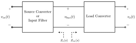
Figure 1.
A typical cascaded system configuration illustrating the source output impedance () and the load input impedance ().
Despite these appealing characteristics of cascaded DC systems, they are susceptible to dynamic performance degradation and instability problems. These problems arise because the load converter tightly regulates its output current or voltage, regardless of the voltage or current variations at the DC bus [7,8,9]. As a consequence, the load converter supplies its load with constant power, so the load converter acts as a power sink attached to the source [10,11]. The small-signal ac analysis of DC-DC converters shows that they have negative input impedance within the bandwidth of their controllers. Therefore, the source converter or the input filter sees the load converter as a negative impedance [12], whereas they are designed to supply non-negative resistive loads [13].
The performance of cascaded systems was first investigated by R.D. Middlebrook in the 1970s. He studied a cascaded system that consisted of a load converter with an input filter. His study concluded that adding the input filter reduces the relative stability margins of the load converter. If the output impedance magnitude () of the filter exceeded the input impedance of the load (), the system would become unstable [14]. On the other hand, represents the closed-loop output impedance, if the source was a DC-DC converter. The ratio of the impedances is referred to as the minor loop gain (), and plays an important role in stability analysis of the overall system.
Several approaches and criteria have been proposed in the literature to ensure stability and proper dynamic performance of cascaded systems. R.D. Middlebrook proposed a criterion that confines the polar plot of within a circle with a radius of in order to ensure stability without degradation in the dynamic performance, where is the gain margin of [14]. The criterion is artificially stringent [8]; it requires high capacitance at the DC bus to be fulfilled. Therefore, other criteria such as gain margin phase margin (GMPM) [15], the opposing argument [16], Energy Source Analysis Consortium (ESAC) [17], three-steps [18], and passivity-based [19] were introduced to relax the conservativeness of the Middlebrook criterion, or to expand its approach to cover a load system that consists of multiple load modules. All criteria are sufficient to ensure stability and/or dynamic performance [20]. Applying the Nyquist criterion to is the only necessary and sufficient condition to ensure both stability and dynamic performance, because all criteria presume that every converter in the system is standalone stable except the three-steps criterion, which defines its minor loop gain differently. Since every converter is standalone stable, the polar plot of must not encircle ()—in the complex plane— in order to ensure stability [21].
The Middlebrook, opposing argument, GMPM, and ESAC are design-oriented criteria [8]. They assume that the output impedance of the source converter is known; hence, the load system must be designed accordingly [22]. This assumption limits the modularity feature of cascaded systems because the dynamic performance would not be guaranteed for any other load converters. Thus, passive damping methods were introduced to damp cascaded systems using bulky passive components connected to the DC bus [7]. Nevertheless, they incur extra power loss, and increase both the system size and weight. As a result, the efficiency, reliability, and power-density of the cascaded systems are compromised.
In order to tackle the drawbacks of passive damping methods, active damping methods have become a popular substitute. The system stability and/or dynamic performance are preserved by modifying the control loop of the source or the load converters. These methods do not typically incur extra power losses; however, some of them reduce the power-density of cascaded systems, such as the solution proposed in [23]. Several noticeable limitations or disadvantages are observed in the proposed solutions in the literature, which can be classified into ensuring stability with poor dynamics (i.e., long settling time) [24], limiting the controller application to a single converter topology (e.g., buck converters) [25,26], and inability to handle multiple converter load systems [27,28,29,30].
In this paper, we propose an active damping method that preserves both the stability and dynamic performance of cascaded systems. The approach is compatible with any minimum-phase DC-DC converter configuration and with any linear feedback control scheme. It is based on shaping the output impedance of the source converter such that its bode-plot is consistently less than the region below the product of the source characteristic impedance and its duty ratio. In addition, a quantifiable approach is proposed to shrink the impedance in that area in order to preserve the dynamic performance without artificial conservativeness.
This paper discusses the dynamic performance of cascaded systems in Section 2. Then, the proposed controller is demonstrated in Section 3. Section 4 illustrates the proposed reshaping method of the source output impedance. Next, a prototype cascaded system is analytically discussed in Section 5, and the analytical results are validated by simulations and experiments in Section 6. Finally, Section 7 sums up the main conclusions and outcomes.
2. Analysis of Cascaded System Dynamics
2.1. Dynamic Performance
The impact of the negative input impedance on cascaded systems can be studied using the canonical model [12] of a single-load-single-source, as shown in Figure 1. For such a system, the input-to-output voltage relationship can be described as
where is the input voltage of the source converter, is the output voltage of the load converter, and and are the input-to-output voltage transfer functions of the source and the load converters, respectively. and denote the voltage loop gains of the source and load converters, respectively. Interconnecting the converters adds more poles to the system due to the added term () in Equation (1), which alters the overall dynamic response of the system [31]. According to Equation (1), if , each converter of the cascaded system will operate as it was individually designed. Hence, the Middlebrook criterion mathematically describes the change in the load converter control-to-output transfer function () as:
where is the source-affected control-to-output transfer function of the load, and is the load input open-loop impedance. In order to minimize the loading impact and eliminate the source-load dynamic coupling,
should hold for the entire range of frequency according to the Middlebrook criterion. Consequently, the extra poles in (1) will be eliminated and . Thus, each converter will operate as initially designed [32]. The terms and are approximately equal to each other within the load controller bandwidth () [33,34]. Diminishing would preserve the dynamic performance of the load converter.
2.2. Impedance Interaction and Instability
is crucial to ensuring both stability and dynamic performance. In order to ensure the stability of the system, () in (1) must have no zeros in the right-half-plane (RHP). These undesirable zeros would occur [20] if and only if:
where and are the phase angles of source output and load input impedances, respectively. Figure 2 shows typical plots of and for kHz. Any impedance overlap that occurs within the controller bandwidth would satisfy (4) because and , which implies that the overall cascaded system will have unstable poles.
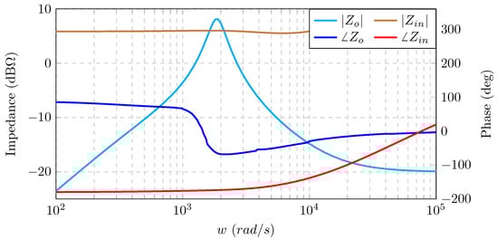
Figure 2.
Typical plots of the source output impedance and the load input impedance , depicting an impedance interaction.
2.3. The Source Performance
The Middlebrook criterion was initially developed to study the impact of the input filter on the performance of DC-DC converters. Replacing the filter with a source DC-DC converter has an impact on the load converter, as described in (2). On the other hand, the loop gain of the source converter is modified by the load converter, due to the loading impact given by [32].
where is the loaded loop gain of the source converter. Similarly, diminishing would preserve the dynamic performance of the source because . In (5), will have RHP poles if and only if satisfies (4).
3. The Proposed Controller
In order to preserve the dynamic performance of voltage mode controlled converters in cascaded systems, the control loop should not change the relationship between the reference voltage () and the output voltage of the converter (), so their relationship has to be preserved as
where is the controller transfer function, and is the pulse-width modulator. In addition, the controller must be capable of actively shaping the output impedance in order to eliminate the impedance interaction between the source and the load converters. Thus, we used the controller topology that is introduced in [35,36], which modified a conventional control scheme, as in Figure 3a, to the controller that is shown in Figure 3b. Then, we modified it to comply with our proposal.
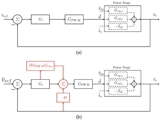
Figure 3.
The block diagram of (a) the conventional controller; and (b) the modified controller emphasizing the modifications in red. PWM: pulse-width modulator.
The output voltage of a standalone converter implementing this controller (displayed in Figure 3b) is expressed as:
where H is the transfer function that is used to shape , and is derived using the open-loop output impedance () as . The variations in the input voltage () can be ignored, because the source voltage is assumed to be ideal. It is noteworthy that we aim to preserve (7), because once the source converter is loaded, the dynamics of the system will be changed by substituting (5) into (7), resulting in the following:
The dynamics of the system in (6) would have been modified if is violated according to (8). In order to eliminate the interaction, we propose to shape the output impedance according to:
where is the reshaped output impedance of the source, and is a constant (its selection method is illustrated in the next section). Reducing as proposed in (9) is challenging because () in (8) is a transfer function whose magnitude should be converted into a constant that equals . Choosing is not a practical choice because the reciprocation results in a transfer function that has more zeros than poles; is a strictly proper transfer function for any DC-DC converter. A transfer function of more zeros than poles is non-realistic. In control theory, such transfer functions describe non-causal systems because their current output depends on their future outcomes. To overcome this impediment, we propose to realize within a certain frequency band using low-pass filters. The transfer function of a low-pass filter () is described [37] as:
where is the cut-off frequency of the filter and is a constant that dictates the order of the low-pass filter to be used. The order of the filter is chosen to ensure as a strictly proper transfer function. For instance, a buck converter has two storage elements (a capacitor and an inductor), so its will be of second order; must be at least equal to 2. Other converters, like the minimum-phase fourth-order buck DC-DC converter [38] have four storage elements; therefore, must be at least 4. Setting:
and then substituting (11) in (8) changes the dominator of the impedance () to:
which can be interpreted as:
Thus, the output voltage of the proposed controller can be re-expressed as:
Figure 4a shows the reshaped output impedance (), using a low-pass filter with rad/s, subjected to different values of . With these proposed modifications to the controller, the magnitude of the source output impedance can be precisely controlled within the filter bandwidth; however, beyond , the magnitude of consistently converges to coincide with the magnitude of .
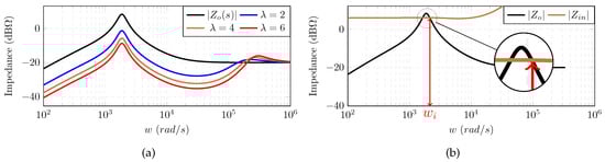
Figure 4.
(a) The shaped output impedance magnitudes using a low-pass filter with rad/s compared to the original output impedance ; and (b) demonstrates the selection of .
Thus, in order to effectively reshape such that the source and the load converters are decoupled, should be greater than , as shown in Figure 4b. Otherwise the shaping will fail to improve the dynamic performance. Ultimately, the implemented controller with the proposed modifications is shown in Figure 5.
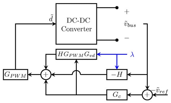
Figure 5.
The proposed controller, emphasizing the modification to the controller in blue.
4. Impedance Reshaping for Decoupling the Source-Load Interaction
The impedance overlap in cascaded systems tends to occur in the vicinity of the peak impedance of the source converter [10]. The dynamic response of the system is compromised due to the impedance interaction around that region. The peak impedance occurs either at the cut-off frequency of the source controller () due to low phase margins, or at the source resonant frequency () if the the bandwidth of the controller was less than the resonance frequency of the converter. In the latter case, the peaking is more severe because DC-DC converters are designed to be highly efficient, which lightly damps the converter. The peaking of the output impedance can be expressed [39] as:
where and are the phase and the gain margins of the source controller, respectively. A low gain or phase margin causes severe peaking, as depicted in Figure 6. For instance, a phase margin of adds dB to the output impedance, while a gain margin of 5 dB adds dB.
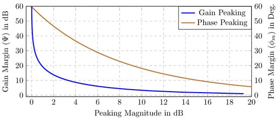
Figure 6.
The peaking caused by the low relative stability margins.
Reducing the magnitude of below to ensure stability is mathematically quantifiable because , within the load controller bandwidth, can be described as [40]:
where is the DC bus voltage, and is the power consumed by the load. Hence, the system will be stable as long as . However, the system dynamic performance would still be compromised if , so we are proposing a method to quantify (≪). The earlier mentioned criteria are used to design the load input impedance. Yet, we propose to shape the output impedance of the source converter to be confined in the region that is below the characteristic impedance of the source converter (), as demonstrated in Figure 7. Shrinking the impedance in the proposed region ensures the dynamic performance of the system, regardless of the attached load. The peaking is more pronounced as the relative stability margins decrease; as a result, the peak impedance will exceed the stability limit. The dynamic performance can be ensured if , so can be reduced to the proposed region of Figure 7 by dividing by:
where is the reduction factor in the magnitude of , and is the peak impedance of . Hence, equating the dominators of ()—which falls in the proposed region—with (9) yields:
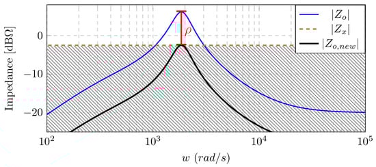
Figure 7.
Plots of and showing the reduction factor with the shaped impedance , where is proposed to be in the hatched area.
Mathematical Validation of Performance Preservation
The shaped output impedance of the source can be expressed as:
As a result, the new minor loop gain () is given by:
so substituting (21) in (5) modifies to as follows:
where is the reshaped loop gain by implementing the proposed shaping in (18).
In addition, the characteristic equation can be rewritten using (18) as:
By inspecting the second term of the denominator, the term , and hence, . As a result, , which validates the proposed shaping method.
5. Theoretical Analysis
The effectiveness of the proposed solution to retain the dynamic performance of cascaded systems has been examined using a prototype that consists of two buck converters connected in series, as shown in Figure 8. The source converter tightly regulates the bus voltage at 7 V, while the load converter was designed to supply a resistive load of 16 W, with an output voltage of 4 V. was chosen to be 1 V. Each converter was devised to be standalone stable, as the polar plots of their voltage loop gains, and , imply in Figure 9. However, cascading the converters was not possible, because the overall system would suffer from instability as impedance overlap occurred, as shown in Figure 10a.
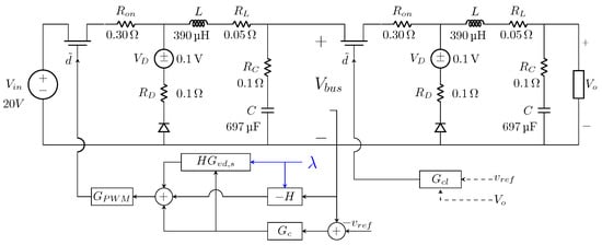
Figure 8.
The prototype cascaded system used for analysis, simulation, and experiment.
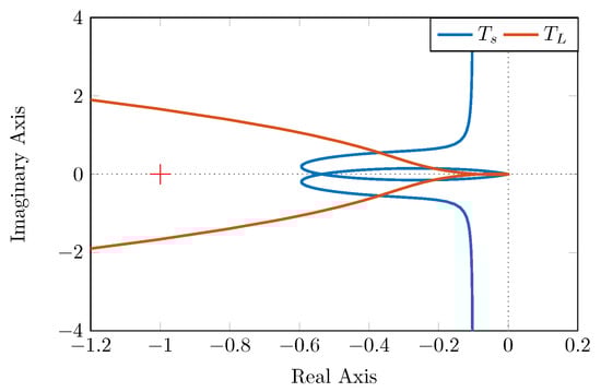
Figure 9.
The loop gains of the source and the load, showing their standalone stability.
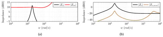
Figure 10.
The impedance analysis of the prototype: (a) showing the interaction between and ; and (b) comparing with the shaped impedance .
Impedance Reshaping and Performance Improvement
In order to preserve both the stability and the dynamic performance of cascaded systems, we propose to shape according to (20). The characteristic impedance of the source converter is , and the peak impedance of the source is dB, which corresponds to . Thus, the resultant divisor factor , using (18), is , which yields . Using Figure 10a, was found to be rad/s, so was set to rad/s. As buck converters have two storage elements, was chosen to be 2 in order to guarantee that H is invertible. Plugging and in (10) gives:
so H, using (11), will be:
As a result, the shaped output impedance of the source converter () is substantially reduced compared to , which emphasizes the ability of the proposed method to decouple the impedances, as shown in Figure 10b.
In order to show the improvement in the dynamic performance, Figure 11 compares the unity feedback closed loop response of to its counterpart . The response of closely tracks its reference response, which highlights the effectiveness of the proposed shaping to stabilize and improve the dynamic performance of cascaded systems.
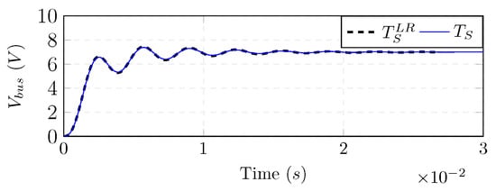
Figure 11.
The unity feedback step response of compared to .
6. Simulation and Experiment Case Studies
6.1. Time-Domain Simulations
The system illustrated in Figure 8 was simulated using PLECS Standalone Package (Plexim, Zurich, Switzerland) in order to evaluate the effectiveness of the proposed controller. Two test cases were carried out. The first test was conducted while the system was at the verge of instability; the load converter was supplying 8 W. Once the system reached steady state, the other 8 W load was added at s. The second test was conducted by starting the system while the load converter was supplying the 16 W in order to compare its response to the theoretical response of .
The system equipped with the conventional controller (as in Figure 3a) was tested in order to demonstrate the impact of the negative input impedance on the system dynamics. For the first test, the system was stable at the start-up with compromised dynamic response because the settling time was compared to in Figure 11. Connecting the other 8 W destabilized the bus voltage permanently, as shown in Figure 12a. Then, the second test was run; Figure 12b shows that the system was also unstable. These tests agree with the analytical analysis, which expected the instability of the system using the conventional controller.
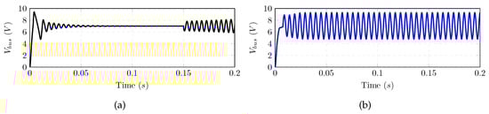
Figure 12.
The instability of the system with the conventional controller: (a) sequential loading; and (b) full loading.
The system was then equipped with the proposed controller as in Figure 5 or Figure 8. The first test was conducted, and the system reached the steady state in . In addition, increasing the output power by 8 W had negligible impact on the system as Figure 13a depicts. Conducting the second test, as shown in Figure 13b, shows that the system response was similar to the of in Figure 11, which proves the effectiveness of the proposed reshaping to stabilize and improve the dynamic performance of cascaded systems.
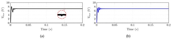
Figure 13.
The improved dynamic response using the proposed method: (a) sequential loading; and (b) full loading.
6.2. Experimental Cases
The prototype cascaded system was physically built as shown in Figure 14. The digital controller platform NIcRio 9024 (National Instruments, Austin, TX, USA) was used to control the output voltages of the converters, with a sampling rate of 30 Ksample/s. Similar to the simulation, the system with the conventional controller was tested using the two test procedures, where denotes the DC bus voltage. Increasing the load sequentially—as in the first test—destabilized the bus voltage as soon as the load power reached 16 W, as shown in Figure 15a. A similar result was yielded by starting up the system supplying the entire load, as shown in Figure 15b. Hence, the determined impact of the negative input impedance is obvious.
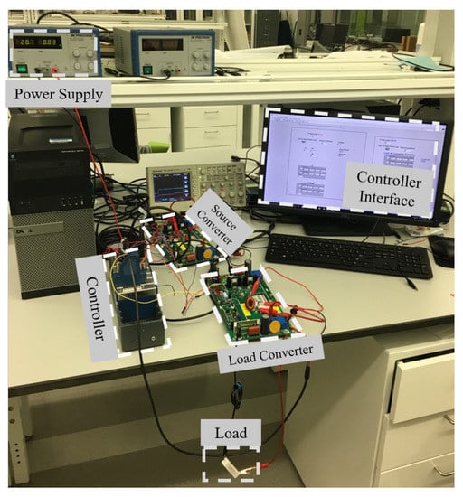
Figure 14.
Experimental prototype set-up.
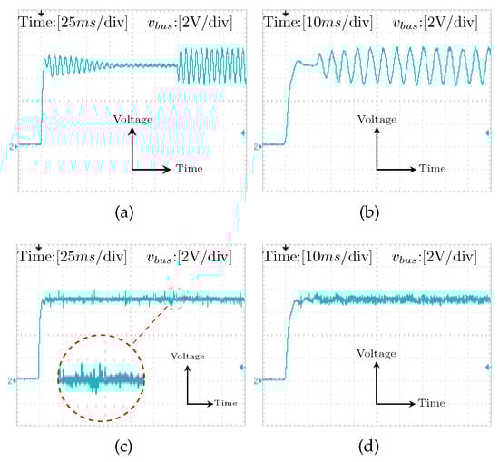
Figure 15.
Experimental results: (a) The instability using the conventional controller by sequential loading; (b) The instability at full load with the conventional controller; (c) The improved performance using the proposed controller with sequential loading; and (d) The response of the system at full loading using the proposed controller.
The proposed controller was implemented to demonstrate its effectiveness in preserving the dynamic performance of the cascaded system. The first test was run, and Figure 15c shows the improvement in the response at the start up, while increasing the load had no impact on the stability of the system. Moreover, the second test was conducted, and the response of the system at the start-up while supplying the entire load was identical to the simulated and theoretical responses of as Figure 15d depicts. Hence, the experimental results have proven the efficacy of the proposed shaping in preserving the dynamic response of cascaded systems.
7. Conclusions
In this paper, we proposed an active damping method to stabilize and retain the dynamic performance of cascaded systems by reshaping the impedance of the source converter. The magnitude of the shaped impedance was absolutely restricted to be in the region limited by the source characteristic impedance in order to prevent dynamic performance degradation. The proposed method is compatible with any linearized feedback control scheme and any DC-DC converter topology. The mathematical approach was developed in order to evaluate every parameter required to shrink the impedance of the source in the proposed region.
A prototype DC cascaded system was built and analyzed, where the performance of the system with and without the proposed method were compared. Analytical analyses, time-domain simulations, and practical experiments have proven the ability of the proposed method to decouple the interaction of the source and the load converters, and hence preserve their dynamic performances. In contrast, the conventional control method suffered from permanent oscillations at the DC bus.
Author Contributions
The authors have participated equally in this work. Analyses, simulations, and experiments were conducted and analyzed by both of the authors.
Conflicts of Interest
The authors declare no conflict of interest.
References
- Dragicevic, T.; Lu, X.; Vasquez, J.C.; Guerrero, J.M. DC microgrids—Part I: A review of control strategies and stabilization techniques. IEEE Trans. Power Electron. 2016, 31, 4876–4891. [Google Scholar] [CrossRef]
- Xu, C.D.; Cheng, K.W.E. A survey of distributed power system—AC versus DC distributed power system. In Proceedings of the 2011 4th International Conference on Power Electronics Systems and Applications, Hong Kong, China, 8–10 June 2011. [Google Scholar]
- Luo, S. A review of distributed power systems part I: DC distributed power system. IEEE Aerosp. Electron. Syst. Mag. 2005, 20, 5–16. [Google Scholar] [CrossRef]
- Du, W.; Zhang, J.; Zhang, Y.; Qian, Z. Stability criterion for cascaded system with constant power load. IEEE Trans. Power Electron. 2013, 28, 1843–1851. [Google Scholar] [CrossRef]
- Ahmadi, R. Dynamic modeling, stability analysis, and controller design for DC distribution systems. Ph.D. Thesis, Missouri University of Science and Technology, Rolla, MO, USA, 2013. [Google Scholar]
- Riccobono, A.; Santi, E. Comprehensive review of stability criteria for DC power distribution systems. IEEE Trans. Ind. Appl. 2014, 50, 3525–3535. [Google Scholar] [CrossRef]
- Cespedes, M.; Xing, L.; Sun, J. Constant-power load system stabilization by passive damping. IEEE Trans. Power Electron. 2011, 26, 1832–1836. [Google Scholar] [CrossRef]
- Sudhoff, S.D.; Corzine, K.A.; Glover, S.F.; Hegner, H.J.; Robey, H.N. DC link stabilized field oriented control of electric propulsion systems. IEEE Trans. Energy Convers. 1998, 13, 27–33. [Google Scholar] [CrossRef]
- Emadi, A.; Ehsani, M.; Miller, J.M. Vehicular Electric Power Systems: Land, Sea, Air, and Space Vehicles; Marcel Dekker: New York, NY, USA, 2004. [Google Scholar]
- Basso, C.P. Designing Control Loops for Linear and Switching Power Supplies: A Tutorial Guide; Artech House: Boston, MA, USA, 2012. [Google Scholar]
- Ioinovici, A. Power Electronics and Energy Conversion Systems; Wiley Academic: Hoboken, New York, NJ, USA, 2013. [Google Scholar]
- Erickson, R.W.; Dragan, M. Fundamentals of Power Electronics; Kluwer Academic: Secaucus, NJ, USA, 2001. [Google Scholar]
- Ang, S.S. Power-Switching Converters; Dekker, M., Ed.; Marcel Dekker Inc.: New York, NY, USA, 1995. [Google Scholar]
- Middlebrook, R.D. Input filter considerations in design and application of switching regulators. In Proceedings of the IEEE Industry Applications Society Annual Meeting, Chicago, IL, USA, 11–14 October 1976. [Google Scholar]
- Wildrick, C.M.; Lee, F.C.; Cho, B.H.; Choi, B. A method of defining the load impedance specification for a stable distributed power system. In Proceedings of the 24th Annual IEEE Power Electronics Specialists Conference (PESC ’93 Record), Seattle, WA, USA, 20–24 June 1993; pp. 826–832. [Google Scholar]
- Feng, X.; Ye, Z.; Xing, K.; Lee, F.C.; Borojevic, D. Impedance specification and impedance improvement for DC distributed power system. In Proceedings of the 30th Annual IEEE Power Electronics Specialists Conference (PESC), Charleston, SC, USA, 1 July 1999; Volume 2, pp. 889–894. [Google Scholar]
- Sudhoff, S.D.; Glover, S.F.; Lamm, P.T.; Schmucker, D.H.; Delisle, D.E. Admittance space stability analysis of power electronic systems. IEEE Trans. Aerosp. Electron. Syst. 2000, 36, 965–973. [Google Scholar]
- Wang, X.; Yao, R.; Rao, F. Three-step impedance criterion for small-signal stability analysis in two-stage DC distributed power systems. IEEE Power Electron. Lett. 2003, 1, 83–87. [Google Scholar] [CrossRef]
- Riccobono, A.; Santi, E. A novel Passivity-Based Stability Criterion (PBSC) for switching converter DC distribution systems. In Proceedings of the 2012 Twenty-Seventh Annual IEEE Applied Power Electronics Conference and Exposition (APEC), Orlando, FL, USA, 5–9 February 2012; pp. 2560–2567. [Google Scholar]
- Hankaniemi, M. Dynamical Profile of Switched-Mode Converter—Fact or Fiction? Ph.D. Thesis, University of Tampere, Tampere, Finland, 2007. [Google Scholar]
- Suntio, T. Dynamic Profile of Switched-Mode Converter: Modeling, Analysis and Control; Wiley-VCH: Weinheim, Germany, 2009. [Google Scholar]
- Sudhoff, S.D.; Crider, J.M. Advancements in generalized immittance based stability analysis of DC power electronics based distribution systems. In Proceedings of the 2011 IEEE Electric Ship Technologies Symposium, Alexandria, VA, USA, 10–13 April 2011. [Google Scholar]
- Zhang, X.; Ruan, X.; Kim, H.; Tse, C.K. Adaptive active capacitor converter for improving stability of cascaded DC power supply system. IEEE Trans. Power Electron. 2013, 28, 1807–1816. [Google Scholar] [CrossRef]
- Wu, M.; Lu, D.D.C. A novel stabilization method of LC input filter with constant power loads without load performance compromise in DC microgrids. IEEE Trans. Ind. Electron. 2015, 62, 4552–4562. [Google Scholar] [CrossRef]
- Cai, W.; Yi, F.; Cosoroaba, E.; Fahimi, B. Stability optimization method based on virtual resistor and nonunity voltage feedback loop for cascaded DC-DC converters. IEEE Trans. Ind. Appl. 2015, 51, 4575–4583. [Google Scholar] [CrossRef]
- Zhang, L.; Ren, X.; Ruan, X. A bandpass filter incorporated into the inductor current feedback path for improving dynamic performance of the front end DC-DC converter in two-stage inverter. IEEE Trans. Ind. Electron. 2014, 61, 2316–2325. [Google Scholar] [CrossRef]
- Ahmadi, R.; Ferdowsi, M. Improving the performance of a line regulating converter in a converter-dominated DC microgrid system. IEEE Trans. Smart Grid 2014, 5, 2553–2563. [Google Scholar] [CrossRef]
- Zhang, X.; Zhong, Q.C.; Ming, W.L. Stabilization of a cascaded DC converter system via adding a virtual adaptive parallel impedance to the input of the load converter. IEEE Trans. Power Electron. 2016, 31, 1826–1832. [Google Scholar] [CrossRef]
- Zhang, X.; Ruan, X.; Zhong, Q.C. Improving the stability of cascaded DC/DC converter systems via shaping the input impedance of the load converter with a parallel or series virtual impedance. IEEE Trans. Ind. Electron. 2015, 62, 7499–7512. [Google Scholar] [CrossRef]
- Ahmadi, R.; Ferdowsi, M. Controller design method for a cascaded converter system comprised of two DC-DC converters considering the effects of mutual interactions. In Proceedings of the 2012 Twenty-Seventh Annual IEEE Applied Power Electronics Conference and Exposition (APEC), Orlando, FL, USA, 5–9 February 2012; pp. 1838–1844. [Google Scholar]
- Pidaparthy, S.K.; Choi, B. Stability analysis of PWM converters connected to general load subsystems. In Proceedings of the 2015 9th International Conference on Power Electronics and ECCE Asia (ICPE-ECCE Asia), Seoul, Korea, 1–5 June 2015; pp. 1033–1040. [Google Scholar]
- Li, P.; Lehman, B. Performance prediction of DC-DC converters with impedances as loads. IEEE Trans. Power Electron. 2004, 19, 201–209. [Google Scholar] [CrossRef]
- Rivetta, C.H.; Emadi, A.; Williamson, G.A.; Jayabalan, R.; Fahimi, B. Analysis and control of a buck DC-DC converter operating with constant power load in sea and undersea vehicles. IEEE Trans. Ind. Appl. 2006, 42, 559–572. [Google Scholar] [CrossRef]
- Zamierczuk, M.K.; Cravens, R.C.; Reatti, A. Closed-loop input impedance of PWM buck-derived DC-DC converters. In Proceedings of the IEEE International Symposium on Circuits and Systems (ISCAS ’94), London, UK, 30 May–2 June 1994; Volume 6, pp. 61–64. [Google Scholar]
- Cao, L.; Loo, K.H.; Lai, Y.M. Systematic derivation of a family of output-impedance shaping methods for power converters—A case study using fuel cell-battery-powered single-phase inverter system. IEEE Trans. Power Electron. 2015, 30, 5854–5869. [Google Scholar] [CrossRef]
- Cao, L.; Loo, K.H.; Lai, Y.M. Output-impedance shaping of bidirectional DAB DC-DC converter using double-proportional-integral feedback for near-ripple-free DC bus voltage regulation in renewable energy systems. IEEE Trans. Power Electron. 2016, 31, 2187–2199. [Google Scholar] [CrossRef]
- Manolakis, D.G.; Ingle, V.K. Applied Digital Signal Processing: Theory and Practice; Cambridge University Press: Cambridge, UK, 2011. [Google Scholar]
- Veerachary, M. Analysis of minimum-phase fourth-order buck DC-DC converter. IEEE Trans. Ind. Electron. 2016, 63, 144–154. [Google Scholar] [CrossRef]
- Wildrick, C.M. Stability of Distributed Power Supply Systems. Ph.D. Thesis, Virginia Polytechnic Institute and State University, Blacksburg, VA, USA, 1993. [Google Scholar]
- Ahmadi, R.; Paschedag, D.; Ferdowsi, M. Analyzing stability issues in a cascaded converter system comprised of two voltage-mode controlled DC-DC converters. In Proceedings of the 2011 Twenty-Sixth Annual IEEE Applied Power Electronics Conference and Exposition (APEC), Fort Worth, TX, USA, 6–11 March 2011; pp. 1769–1775. [Google Scholar]
© 2017 by the authors. Licensee MDPI, Basel, Switzerland. This article is an open access article distributed under the terms and conditions of the Creative Commons Attribution (CC BY) license (http://creativecommons.org/licenses/by/4.0/).