
Sustainability of the Renewable Energy Extraction Close to the Mediterranean Islands


Abstract
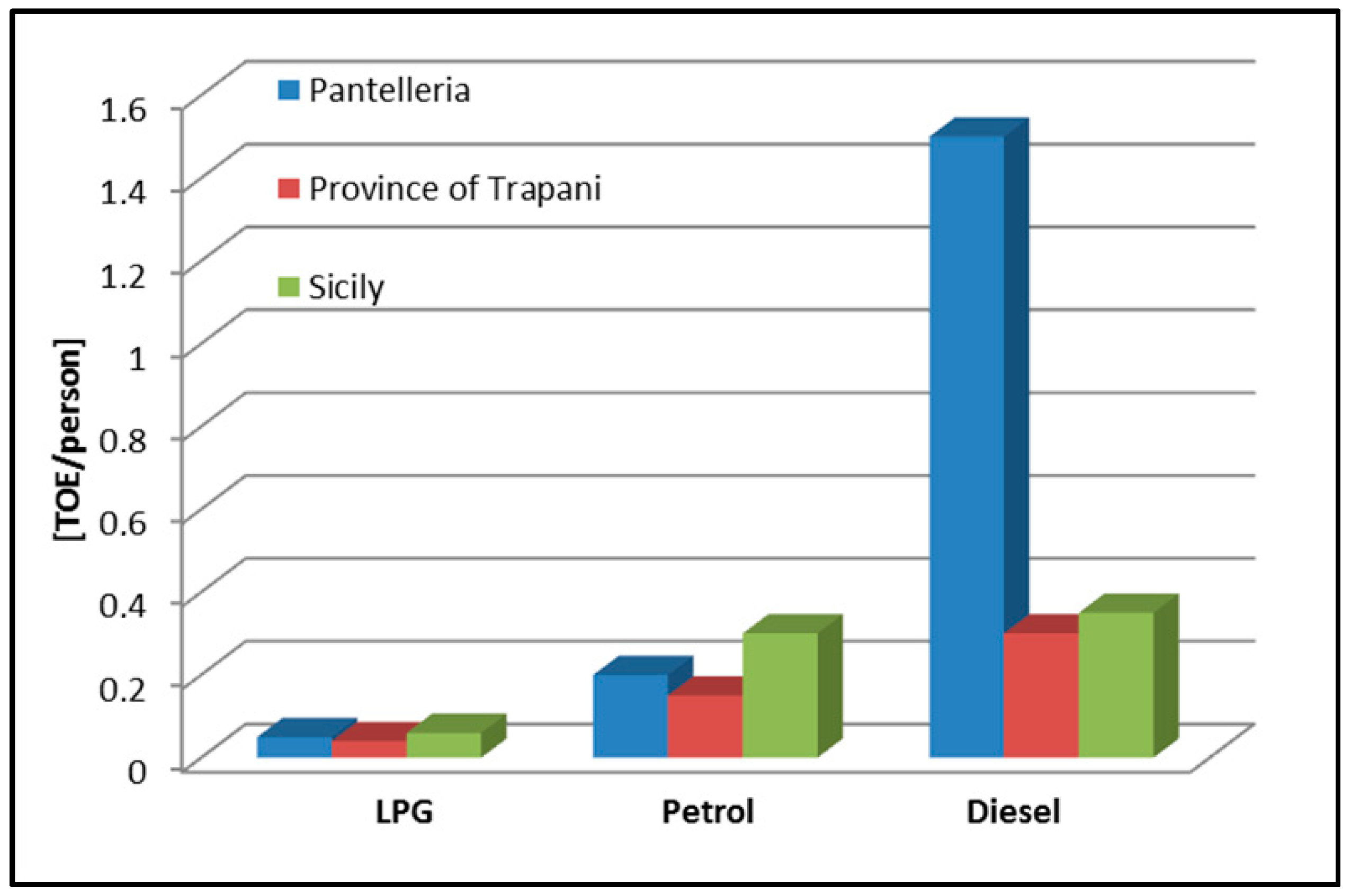
:1. Introduction
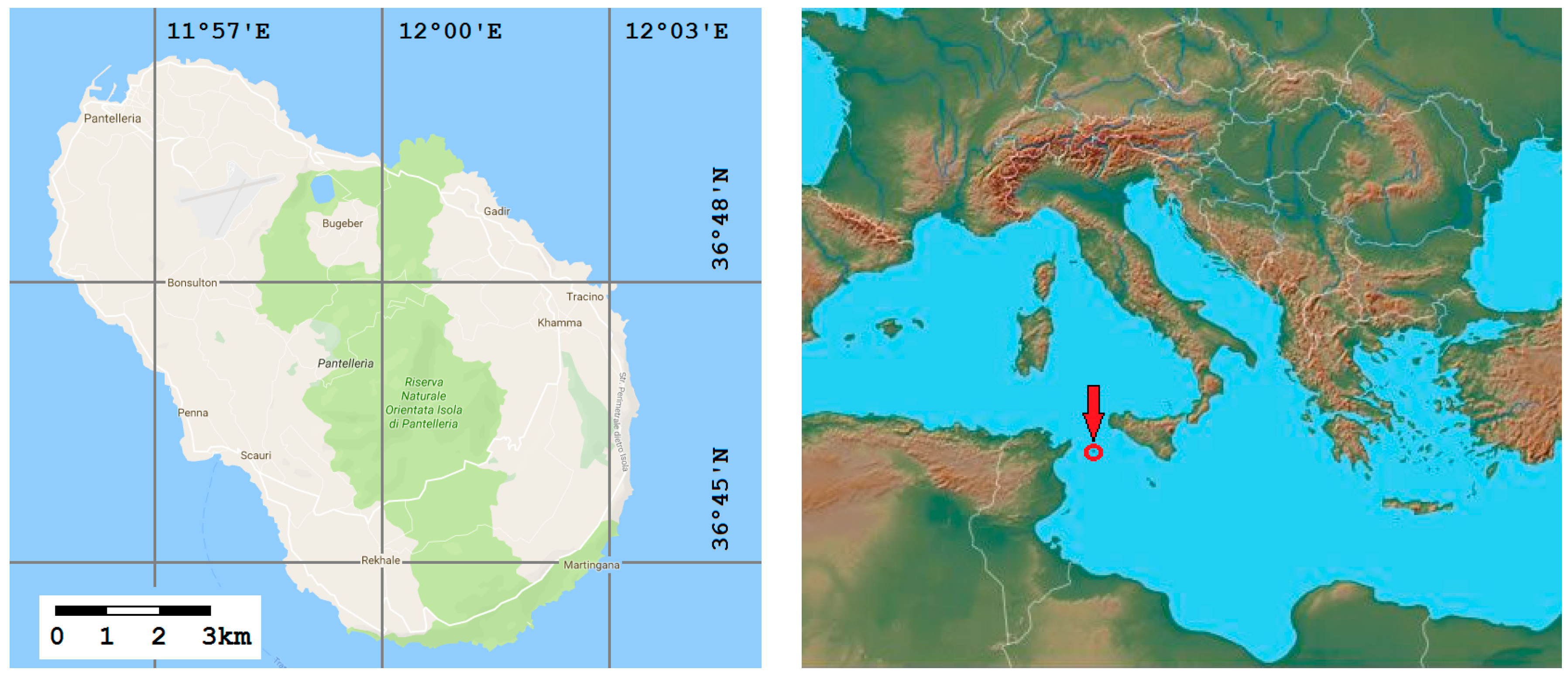
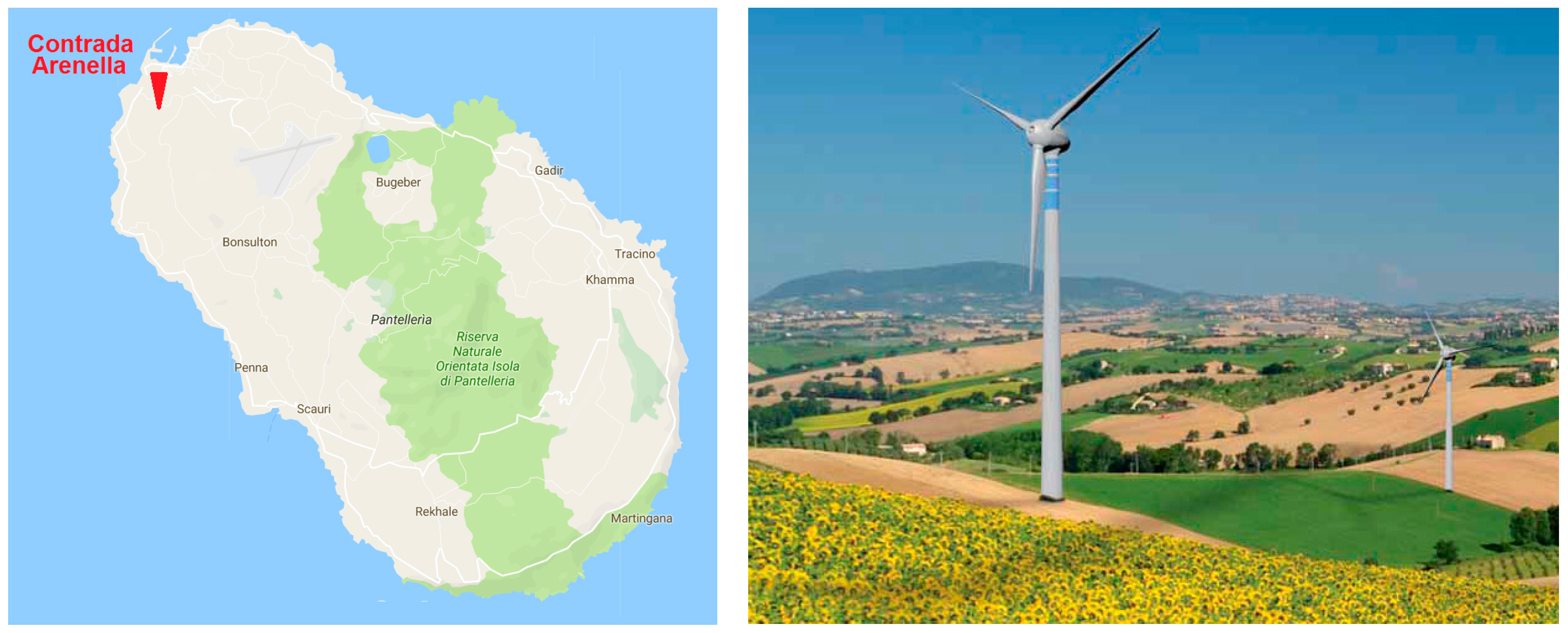
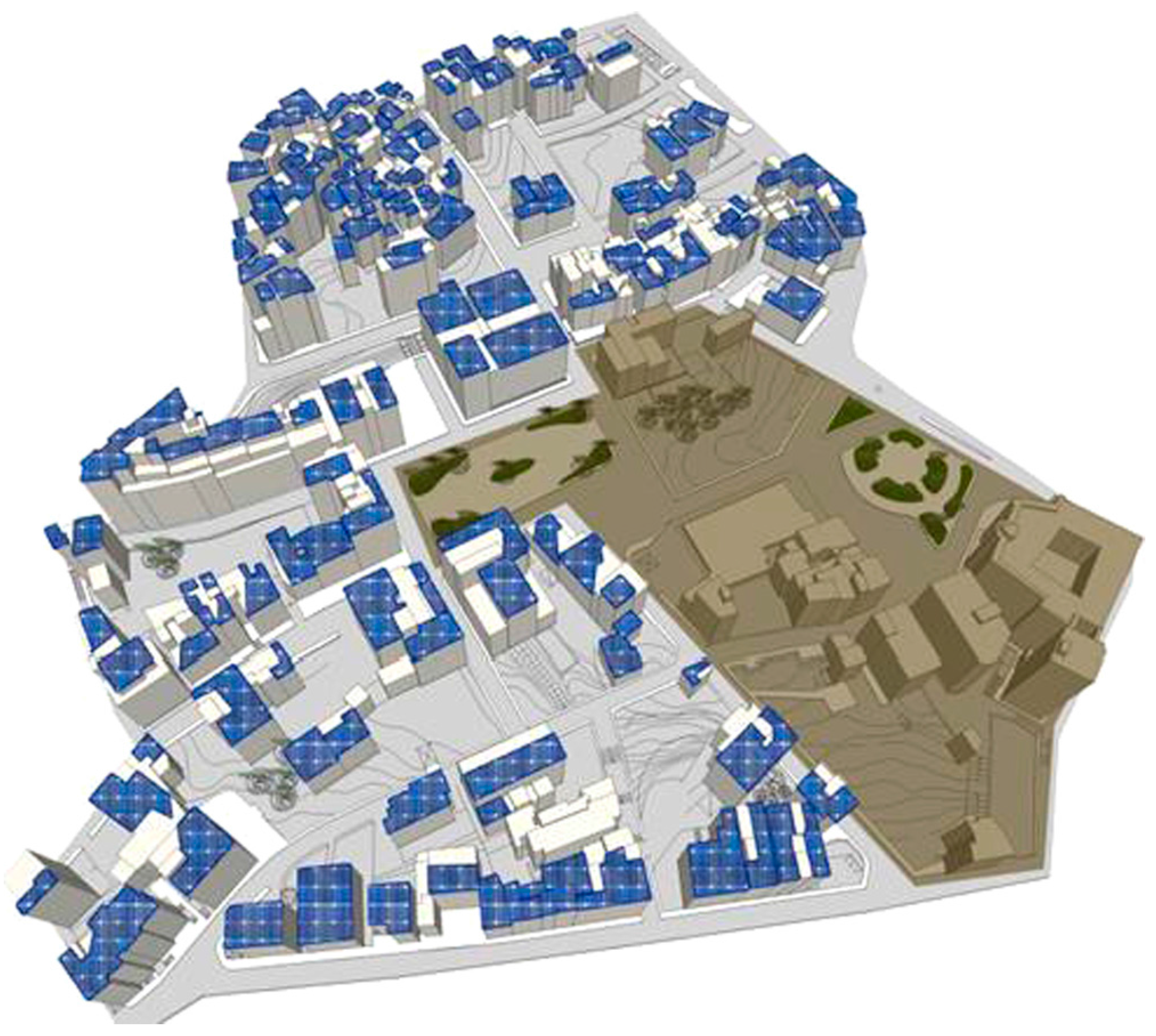
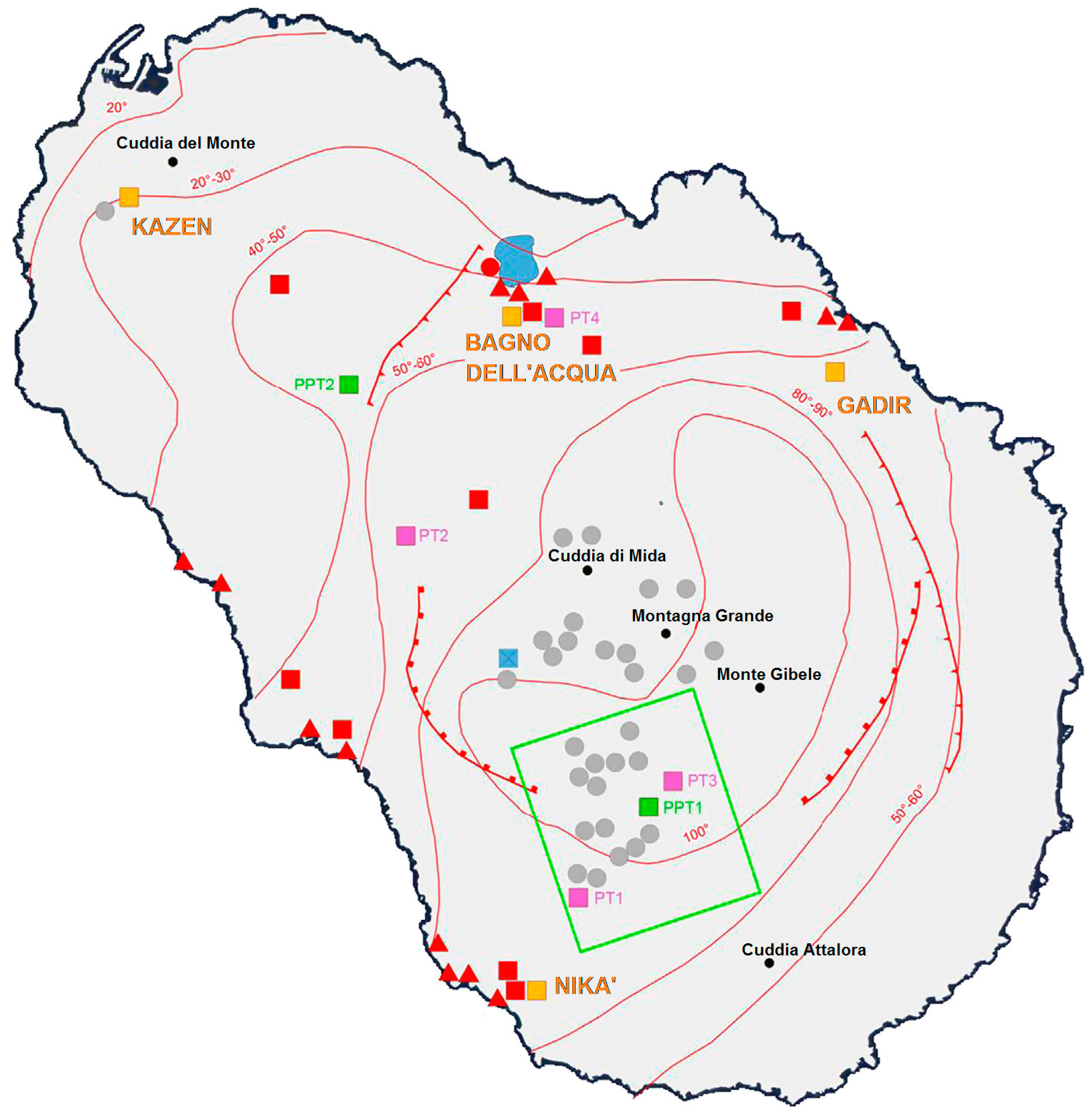
2. Pantelleria’s Environmental Policies and Landscape
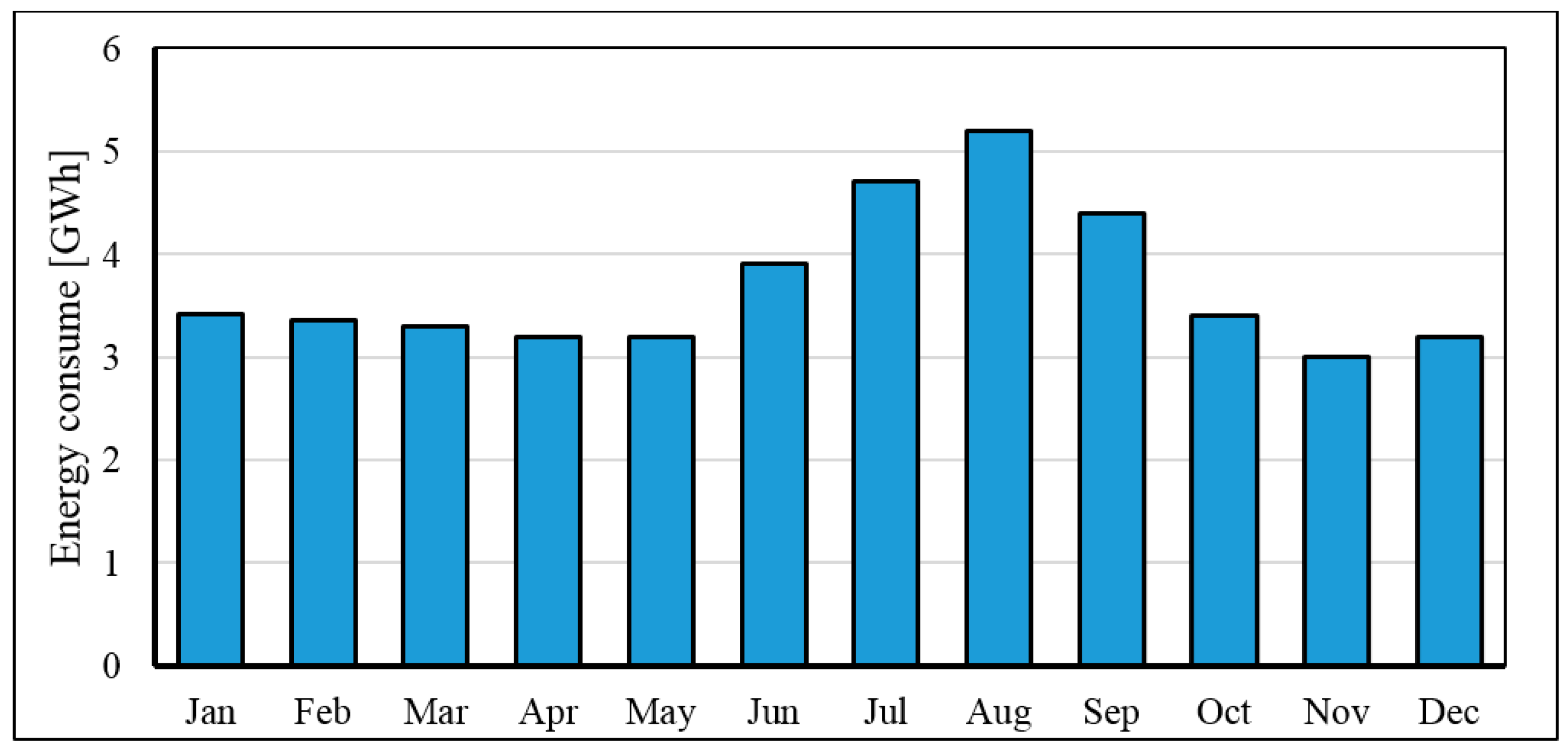
3. Electrical Energy Production
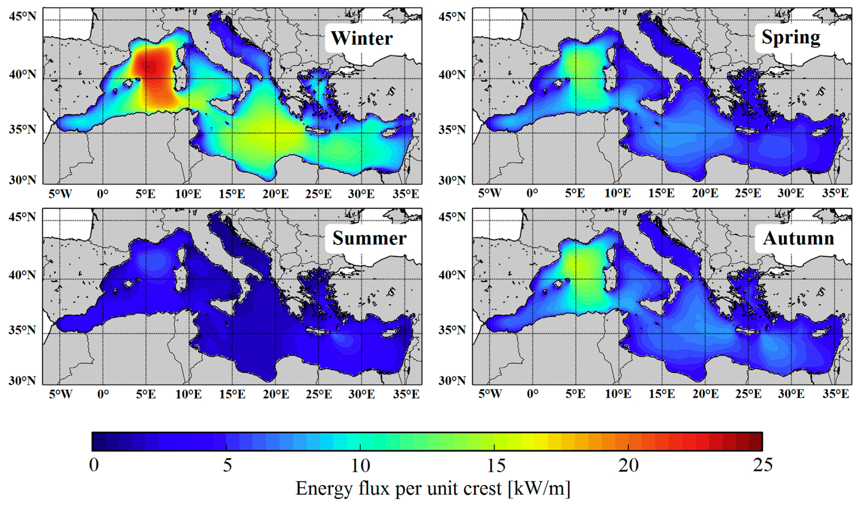
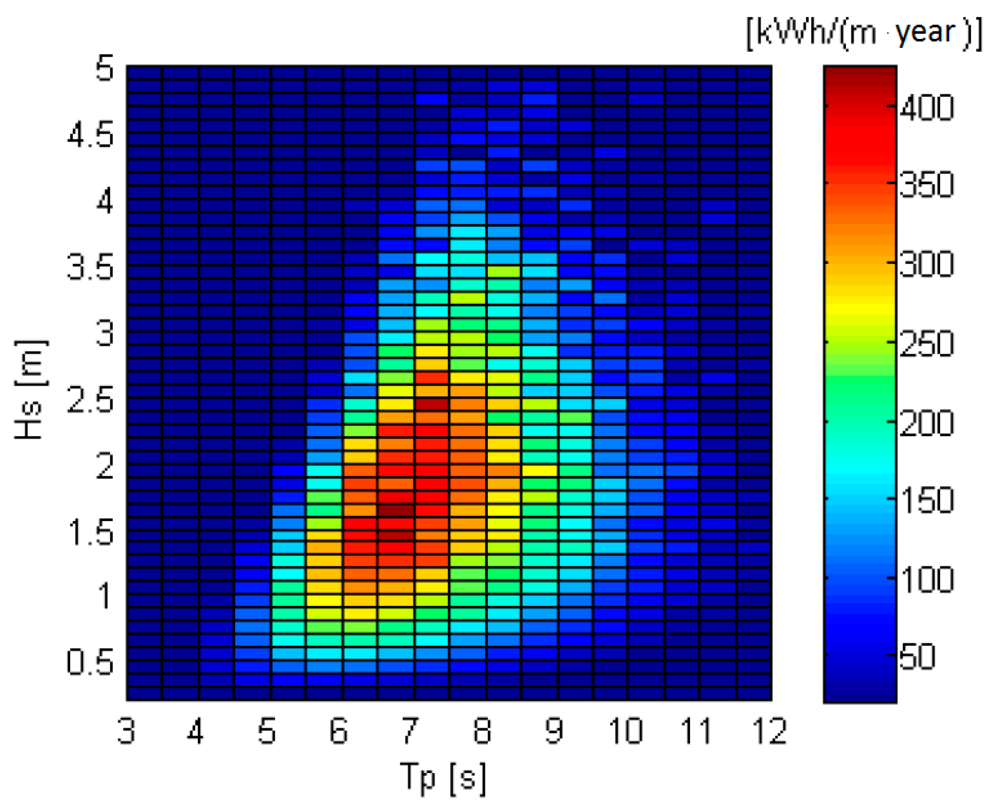
4. Seawave Energy Resource
5. Mathematical Modeling
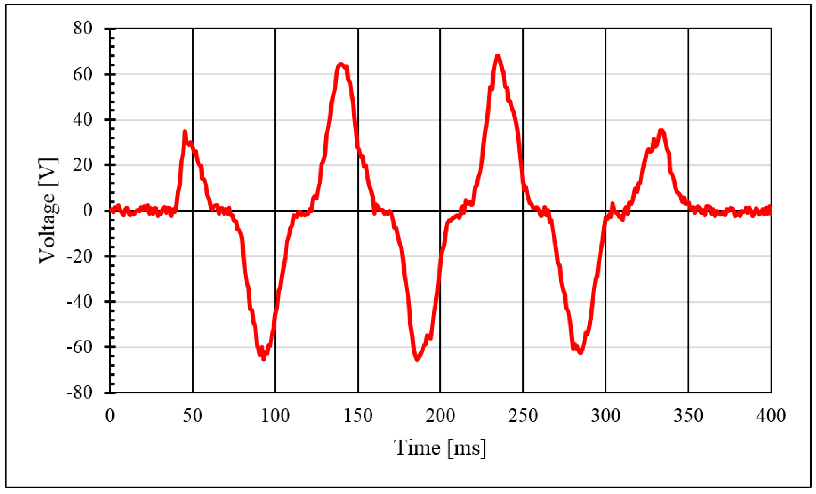
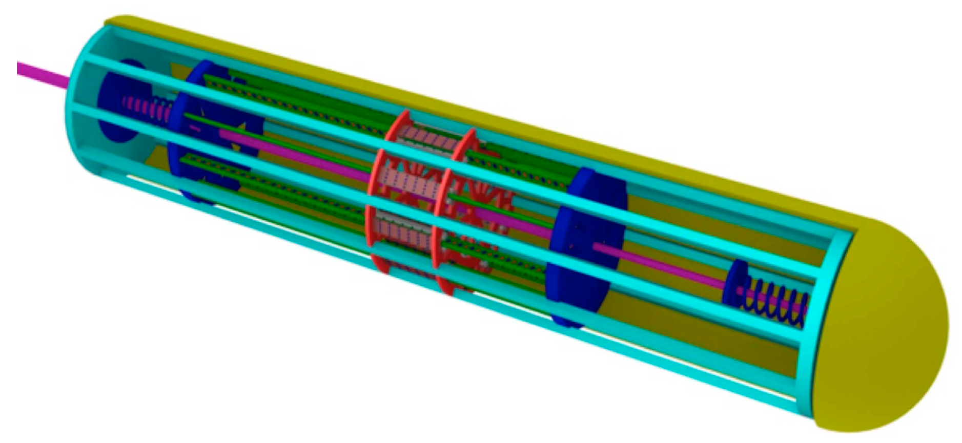
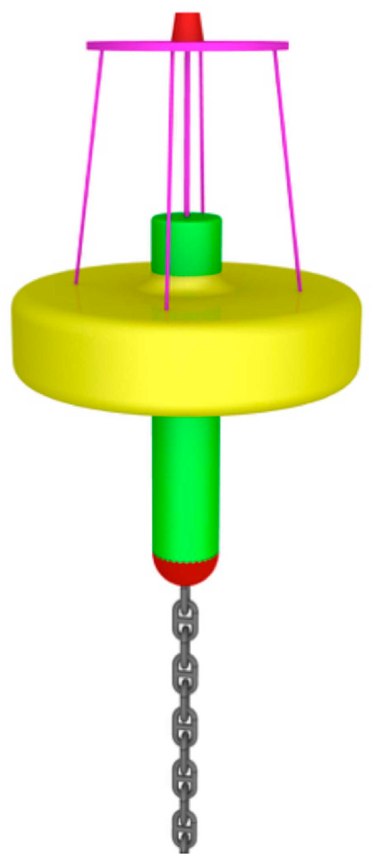
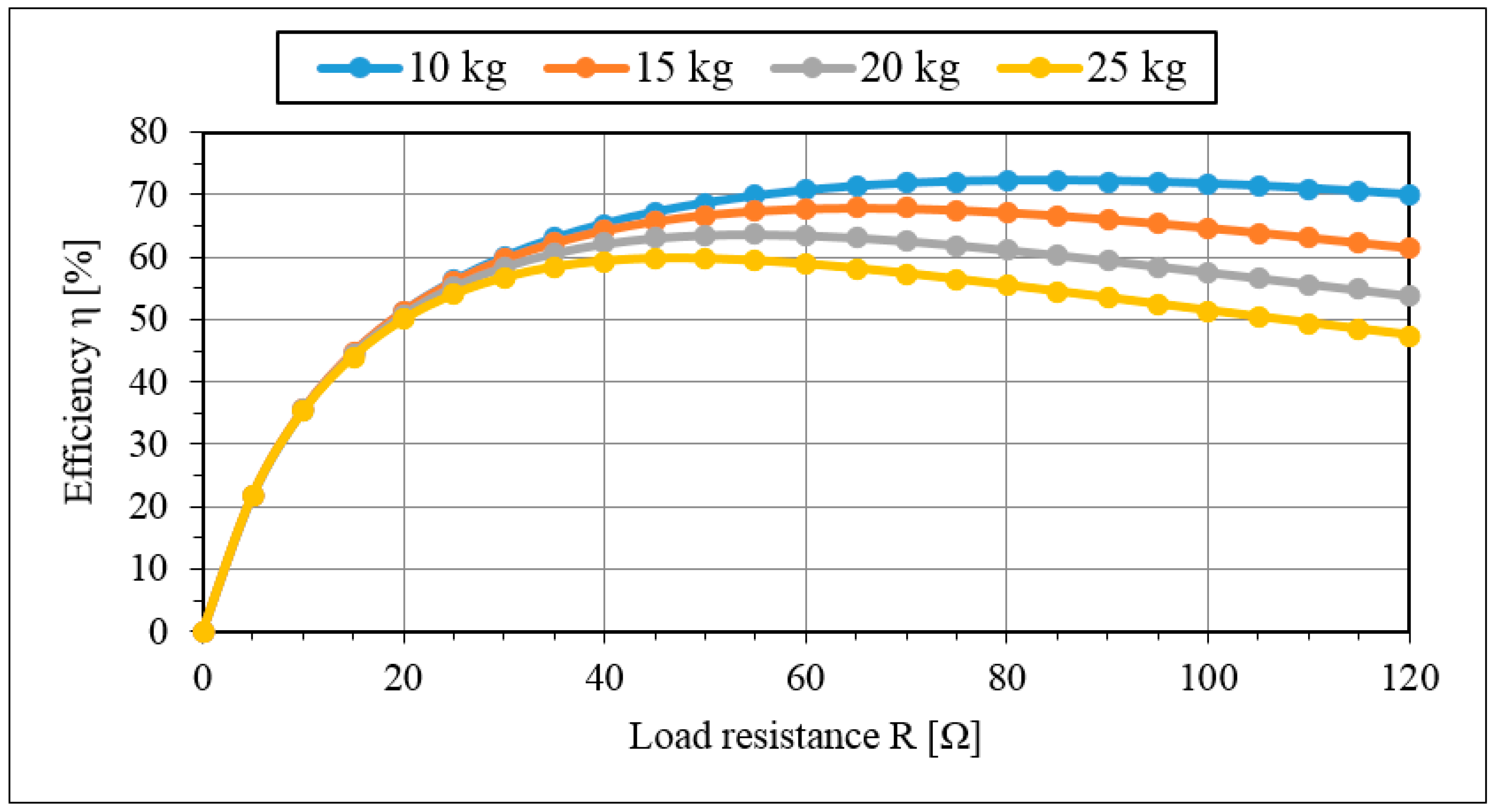
6. DEIM Point Absorber
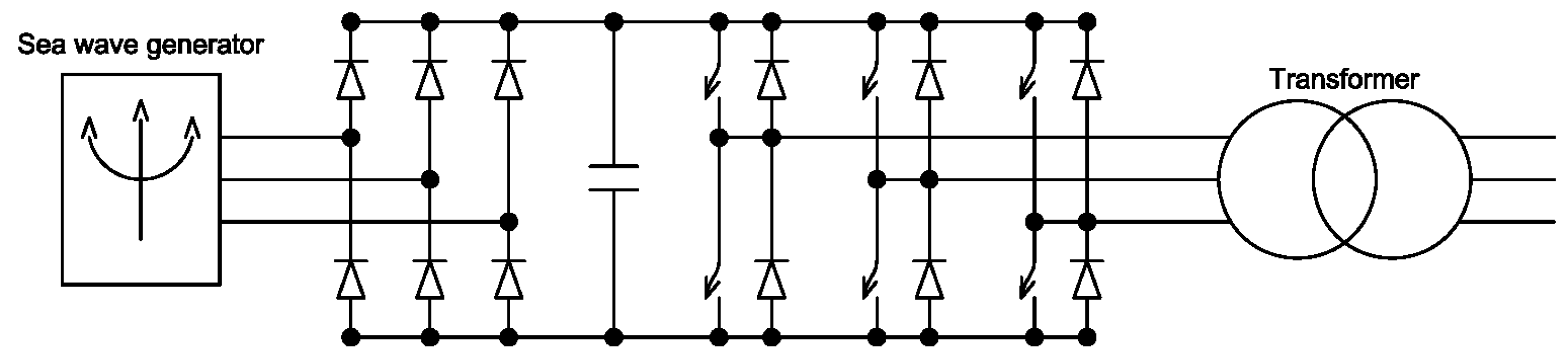
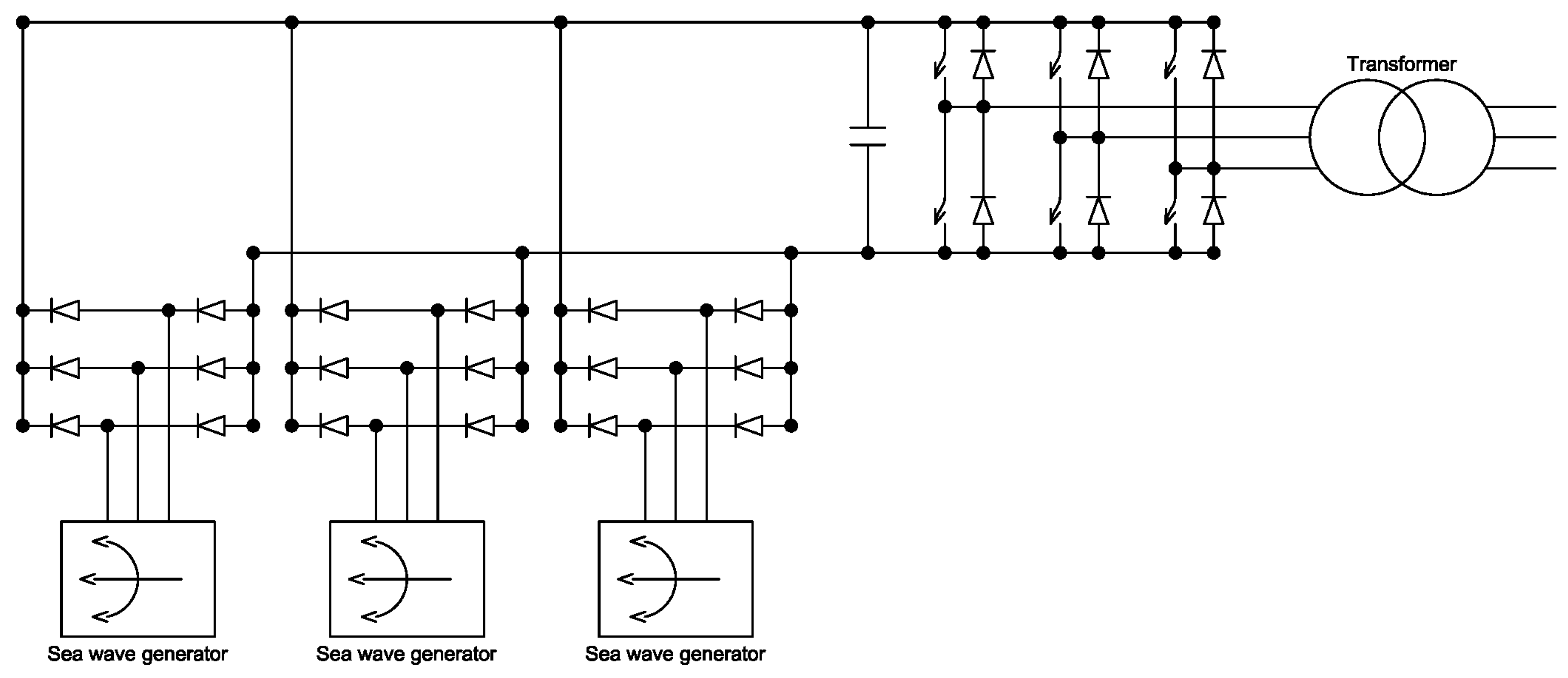
7. Interconnection Solutions
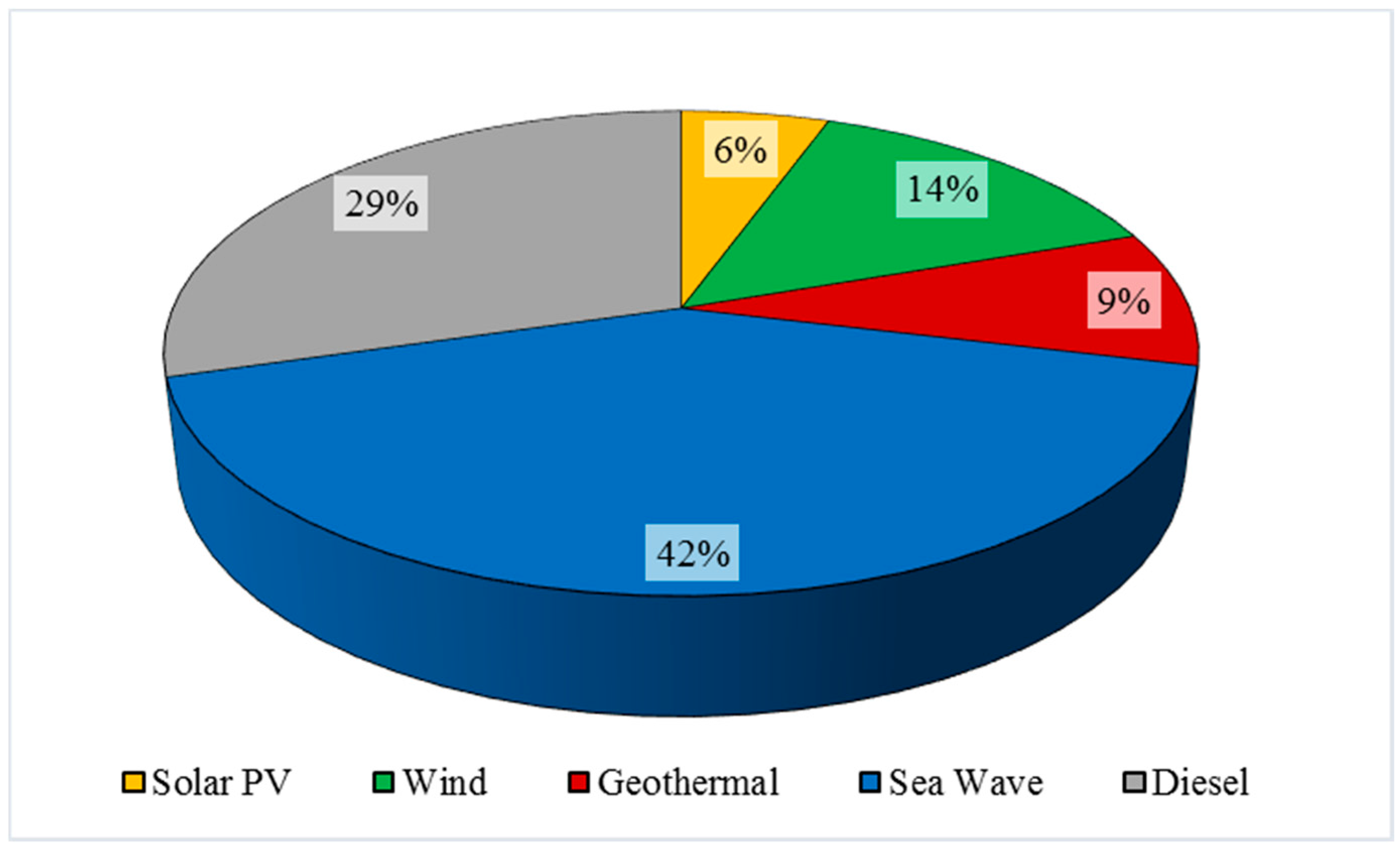
8. Scenarios
8.1. Solar Source
8.2. Wind Source
8.3. Geothermal Source
8.4. Wave Source
9. Conclusions
Conflicts of Interest
Abbreviations
| Significant height of sea waves | |
| Peak period of sea waves | |
| Main direction of sea waves | |
| Total mass of power take off system | |
| Mass of the fluid, displaced by the buoy | |
| Vertical position of the floating buoy, measured from the equilibrium condition | |
| Vertical speed of the floating buoy | |
| Vertical velocity of the free water surface | |
| Vertical acceleration of the floating buoy | |
| Sum of the hydrodynamic forces applied to the power take off system | |
| Sum of the resistance forces applied to the power take off system | |
| Electromagnetic braking force | |
| Elastic force of the spring system | |
| Radiation damping coefficient | |
| Viscous damping coefficient | |
| Sea water density | |
| Water plane area of the body at rest | |
| Gravitational acceleration constant | |
| Amplitude of the excitation force | |
| Wave height | |
| Wave frequency | |
| Wave angular phase | |
| Elastic stiffness constant of the spring | |
| Voltage generated in the stator | |
| Magnetic field evaluated in stator tooth | |
| Width of a stator tooth | |
| d | Width of the stator stack |
| p | Total number of poles |
| Number of slots per pole and phase | |
| c | Number of coils in a slot |
| Pole width | |
| δ | Load angular phase |
| Output voltage in the electrical generator | |
| Output current in the electrical generator | |
| Time derivative of the current | |
| Internal resistance of the windings | |
| Load resistance | |
| Circuit inductance | |
| Output power of the electrical generator |
References
- Di Dio, V.; Franzitta, V.; Milone, D.; Pitruzzella, S.; Trapanese, M.; Viola, A. Design of Bilateral Switched Reluctance Linear Generator to Convert Wave Energy: Case Study in Sicily. Adv. Mater. Res. 2013, 860, 1694–1698. [Google Scholar] [CrossRef]
- Franzitta, V.; Milone, A.; Milone, D.; Pitruzzella, S.; Trapanese, M.; Viola, A. Experimental Evidence on the Thermal Performance of Opaque Surfaces in Mediterranean Climate. Adv. Mater. Res. 2014, 860, 1227–1231. [Google Scholar] [CrossRef]
- Franzitta, V.; Rizzo, G. Renewable energy sources: A Mediterranean perspective. In Proceedings of the 2010 2nd International Conference on Chemical, Biological and Environmental Engineering, Cairo, Egypt, 2–4 November 2010; pp. 48–51.
- Franzitta, V.; Milone, D.; Trapanese, M.; Viola, A.; di Dio, V.; Pitruzzella, S. Energy and Economic Comparison of Different Conditioning System among Traditional and Eco-Sustainable Building. Appl. Mech. Mater. 2013, 394, 289–295. [Google Scholar] [CrossRef]
- Cannistraro, G.; Cannistraro, M.; Cannistraro, A.; Galvagno, A.; Trovato, G. Reducing the Demand of Energy Cooling in the CED, ‘Centers of Processing Data’, with Use of Free-Cooling Systems. Int. J. Heat Technol. 2016, 34, 498–502. [Google Scholar] [CrossRef]
- Franzitta, V.; Curto, D.; Rao, D. Energetic Sustainability Using Renewable Energies in the Mediterranean Sea. Sustainability 2016, 8, 1164. [Google Scholar] [CrossRef]
- Gestore Servizi Energetici. Rapporto Statistico—Energia da Fonti Rinnovabili—Anno 2013; Gestore Servizi Energetici (GSE): Rome, Italy, 2015. [Google Scholar]
- Cagninei, A.; Raffero, M.; Bracco, G.; Giorcelli, E.; Mattiazzo, G.; Poggi, D. Productivity analysis of the full scale inertial sea wave energy converter prototype: A test case in Pantelleria Island. J. Renew. Sustain. Energy 2015, 7, 61703. [Google Scholar] [CrossRef]
- Bueno, C.; Carta, J.A. Wind powered pumped hydro storage systems, a means of increasing the penetration of renewable energy in the Canary Islands. Renew. Sustain. Energy Rev. 2006, 10, 312–340. [Google Scholar] [CrossRef]
- Franzitta, V.; Curto, D.; Rao, D.; Milone, D. Near zero energy island with sea wave energy: The case study of Pantelleria in Mediterranean Sea. In Proceedings of the OCEANS 2016, Shanghai, China, 10–13 April 2016; pp. 1–5.
- Sanseverino, E.R.; Sanseverino, R.R.; Favuzza, S.; Vaccaro, V. Near zero energy islands in the Mediterranean: Supporting policies and local obstacles. Energy Policy 2014, 66, 592–602. [Google Scholar] [CrossRef]
- Piano D’azione per L’energia Sostenibile del Comune di Pantelleria. Available online: http://www.smartisland.eu/images/documenti_report/Pantelleria_Paes.pdf (accessed on 9 December 2016).
- Cannistraro, G.; Cannistraro, M.; Piccolo, A.; Restivo, R. Potentials and Limits of Oxidative Photocatalysisand Possible Applications in the Field of Cultural Heritage. Adv. Mater. Res. 2013, 787, 111–117. [Google Scholar] [CrossRef]
- Cannistraro, G.; Cannistraro, M. Hypothermia Risk, Monitoring and Environment Control in Operating Rooms. Int. J. Heat Technol. 2016, 34, 165–171. [Google Scholar] [CrossRef]
- Tuttitalia.it. Popolazione Pantelleria 2001–2015. Statistiche Demografice. 2016. Available online: http://www.tuttitalia.it/sicilia/31-pantelleria/statistiche/popolazione-andamento-demografico/ (accessed on 13 November 2016).
- Cosentino, V.; Favuzza, S.; Graditi, G.; Ippolito, M.G.; Massaro, F.; Sanseverino, E.R.; Zizzo, G. Smart renewable generation for an islanded system. Technical and economic issues of future scenarios. Energy 2012, 39, 196–204. [Google Scholar] [CrossRef]
- Viola, A.; Franzitta, V.; Trapanese, M.; Curto, D. Nexus Water & Energy: A Case Study of Wave Energy Converters (WECs) to Desalination Applications in Sicily. Int. J. Heat Technol. 2016, 34, S379–S386. [Google Scholar]
- Peviani, M.; Carli, F.; Bonamano, S. Mappa del Potenziale Energetico dal Moto Ondoso Nelle Coste Italiane; Ricerca Sistema Energetico (RSE): Milan, Italy, 2011. [Google Scholar]
- Booij, N.; Ris, R.C.; Holthuijsen, L.H. A third-generation wave model for coastal regions: 1. Model description and validation. J. Geophys. Res. Ocean. 1999, 104, 7649–7666. [Google Scholar] [CrossRef]
- Liberti, L.; Sann, G.; Carillo, A. Wave energy potential in the Mediterranean, the case of Pantelleria. In Proceedings of the OWEMES (Offshore Wind and Other Marine Renewable Energies) 2012, Rome, Italy, 5–7 September 2012.
- Franzitta, V.; Trapanese, M.; Giaconia, C.; Ferrara, P.; Viola, A. Design and experimental test of a low costweather buoy. In Proceedings of the 2013 MTS (Marine Technology Society)/IEEE (Institute of Electrical and Electronics Engineers) OCEANS, Bergen, Norway, 10–13 June 2013; pp. 1–5.
- Mattiazzo, G.; Giorcelli, E.; Poggi, D.; Sannino, G.; Carillo, A. Progettazione di un Sistema di Produzione di Energia da Moto Ondoso in Scala Reale; Agenzia nazionale per le nuove tecnologie, l’energia e lo sviluppo economico sostenibile (ENEA): Rome, Italy, 2013. [Google Scholar]
- Lockett, F.P. Mathematical modelling of wave energy systems. Renew. Energy 1996, 9, 1213–1217. [Google Scholar] [CrossRef]
- Franzitta, V.; Viola, A.; Trapanese, M. Design of a transverse flux machine for power generation from seawaves. J. Appl. Phys. 2014, 115, 17E712. [Google Scholar] [CrossRef]
- Bonanno, A.; Franzitta, V.; Muzio, F.P.; Trapanese, M. A multiphysics approach to the design of a seawave energy conversion system. In Proceedings of the 2008 IEEE International Conference on Sustainable Energy Technologies, Singapore, 24–27 November 2008; pp. 665–668.
- McCabe, A.P.; Aggidis, G.A. Optimum mean power output of a point-absorber wave energy converter in irregular waves. Proc. Inst. Mech. Eng. Part A J. Power Energy 2009, 223, 773–781. [Google Scholar] [CrossRef]
- Munson, B.R.; Young, D.F.; Okiishi, T.H.; Huebsch, W.W. Fundamentals of Fluid Mechanics, 6th ed.; Wiley: Somerset, NJ, USA, 2009. [Google Scholar]
- McCormick, M.E. Ocean Engineering Mechanics; Cambridge University Press: Cambridge, UK, 2009. [Google Scholar]
- Thorburn, K.; Leijon, M. Farm size comparison with analytical model of linear generator wave energy converters. Ocean Eng. 2007, 34, 908–916. [Google Scholar] [CrossRef]
- Trapanese, M.; Franzitta, V.; Viola, A. A dynamic model for hysteresis in magnetostrictive devices. J. Appl. Phys. 2014, 115, 1–4. [Google Scholar] [CrossRef]
- Miceli, R.; Trapanese, M. Evaluation of the power quality from a seawave power farm for different interconnection schemes. In Proceedings of the OCEANS 2007, Aberdeen, UK, 18–21 June 2007; pp. 1–4.
- Bozzi, S.; Miquel, A.; Antonini, A.; Passoni, G.; Archetti, R. Modeling of a Point Absorber for Energy Conversion in Italian Seas. Energies 2013, 6, 3033–3051. [Google Scholar] [CrossRef]
- ANSYS Inc. AQWA User Manual—Release 14.5. Available online: https://cyberships.files.wordpress.com/2014/01/wb_aqwa.pdf (accessed on 9 December 2016).
- Falnes, J. Ocean Waves and Oscillating Systems: Linear Interactions Including Wave-Energy Extraction; Cambridge University Press: Cambridge, UK, 2002. [Google Scholar]
- Milone, D.; Pitruzzella, S.; Franzitta, V.; Viola, A.; Trapanese, M. Energy savings through integration of the illumination natural and artificial, using a system of automatic dimming: Case study. Appl. Mech. Mater. 2013, 372, 253–258. [Google Scholar] [CrossRef]
- Franzitta, V.; di Dio, V.; Viola, A.; Giaconia, C.; Ferrara, P.; Trapanese, M. Experimental results of a low cost weather buoy. In Proceedings of the 2013 OCEANS, San Diego, CA, USA, 23–27 September 2013.
- Silva, D.; Rusu, E.; Soares, C. Evaluation of Various Technologies for Wave Energy Conversion in the Portuguese Nearshore. Energies 2013, 6, 1344–1364. [Google Scholar] [CrossRef]
- Rusu, E. Evaluation of the Wave Energy Conversion Efficiency in Various Coastal Environments. Energies 2014, 7, 4002–4018. [Google Scholar] [CrossRef]
- Vantorre, M.; Banasiak, R.; Verhoeven, R. Modelling of hydraulic performance and wave energy extraction by a point absorber in heave. Appl. Ocean Res. 2004, 26, 61–72. [Google Scholar] [CrossRef]
- Polinder, H.; Damen, M.E.C.; Gardner, F. Linear PM Generator System for Wave Energy Conversion in the AWS. IEEE Trans. Energy Convers. 2004, 19, 583–589. [Google Scholar] [CrossRef]
- Boscaino, V.; Cipriani, G.; Curto, D.; di Dio, V.; Franzitta, V.; Trapanese, M.; Viola, A. A small scale prototype of a wave energy conversion system for hydrogen production. In Proceedings of the IECON 2015 41st Annual Conference of the IEEE Industrial Electronics Society, Yokohama, Japan, 9–12 November 2015.
- Franzitta, V.; Milone, A.; Milone, D.; Pitruzzella, S.; Trapanese, M.; Viola, A. A Case Study to Evaluate the Indoor Global Quality. Adv. Mater. Res. 2013, 864, 1054–1058. [Google Scholar] [CrossRef]
- Aerogeneratore ItalTech 50 kW—DataSheet. 2016. Available online: http://www.italtechwind.it/it/utility/pdf/aerogeneratore_italtechwind_60kw.pdf (accessed on 20 January 2017).
- Mattia, M.; Bonaccorso, A.; Guglielmino, F. Ground deformations in the Island of Pantelleria (Italy): Insights into the dynamic of the current intereruptive period. J. Geophys. Res. 2007, 112, B11406. [Google Scholar] [CrossRef]
- Gianelli, G.; Grassi, S. Water–rock interaction in the active geothermal system of Pantelleria, Italy. Chem. Geol. 2001, 181, 113–130. [Google Scholar] [CrossRef]


| Parameter | Value |
|---|---|
| Average annual solar radiation | 1.69 MWh/(m2·year) |
| Minimum daily solar radiation (January) | 1.90 kWh/(m2·day) |
| Maximum daily solar radiation (July) | 7.20 kWh/(m2·day) |
| Parameter | Value |
|---|---|
| Rated power | 50 kW |
| Cut-in speed | 3 m/s |
| Cut-off speed | 25 m/s |
| Rotor diameter | 18 m |
| Rotor surface | 254 m2 |
| Hub height | 25 m |
| Rotational speed | 25–70 rpm |
| Parameter | Value |
|---|---|
| Available flow | 4 t/h |
| Temperature | 250 °C |
| Pressure | 13.5 bar |
| Enthalpy | 2929.9 kJ/kg |
| Parameter | Value |
|---|---|
| Steam flow | 2.7 t/h |
| Condensing pressure | 0.05 bar |
| Isentropic Efficiency | 0.8 |
| Organic Efficiency | 0.96 |
| Power output | 500 kW |
| Annual working hours | 8000 h/y |
| Annual electrical production | 4 GWh |
| Sources | Annual Electrical Production | Avoided CO2 Emissions |
|---|---|---|
| Solar Photovoltaic | 2440 | 1952 |
| Wind | 6250 | 5000 |
| Geothermal | 4000 | 3200 |
| Sea Wave | 18,396 | 14,717 |
| Diesel | 14,764 | - |
© 2017 by the authors. Licensee MDPI, Basel, Switzerland. This article is an open access article distributed under the terms and conditions of the Creative Commons Attribution (CC BY) license ( http://creativecommons.org/licenses/by/4.0/).
Share and Cite
Franzitta, V.; Curto, D. Sustainability of the Renewable Energy Extraction Close to the Mediterranean Islands. Energies 2017, 10, 283. https://doi.org/10.3390/en10030283
Franzitta V, Curto D. Sustainability of the Renewable Energy Extraction Close to the Mediterranean Islands. Energies. 2017; 10(3):283. https://doi.org/10.3390/en10030283
Chicago/Turabian StyleFranzitta, Vincenzo, and Domenico Curto. 2017. "Sustainability of the Renewable Energy Extraction Close to the Mediterranean Islands" Energies 10, no. 3: 283. https://doi.org/10.3390/en10030283
APA StyleFranzitta, V., & Curto, D. (2017). Sustainability of the Renewable Energy Extraction Close to the Mediterranean Islands. Energies, 10(3), 283. https://doi.org/10.3390/en10030283