Experimental and Finite Element Analysis to Investigate the Vibration of Oblique-Stud Stator Frame in a Large Hydropower Generator Unit


Abstract
:1. Introduction
2. Field Experimental Tests
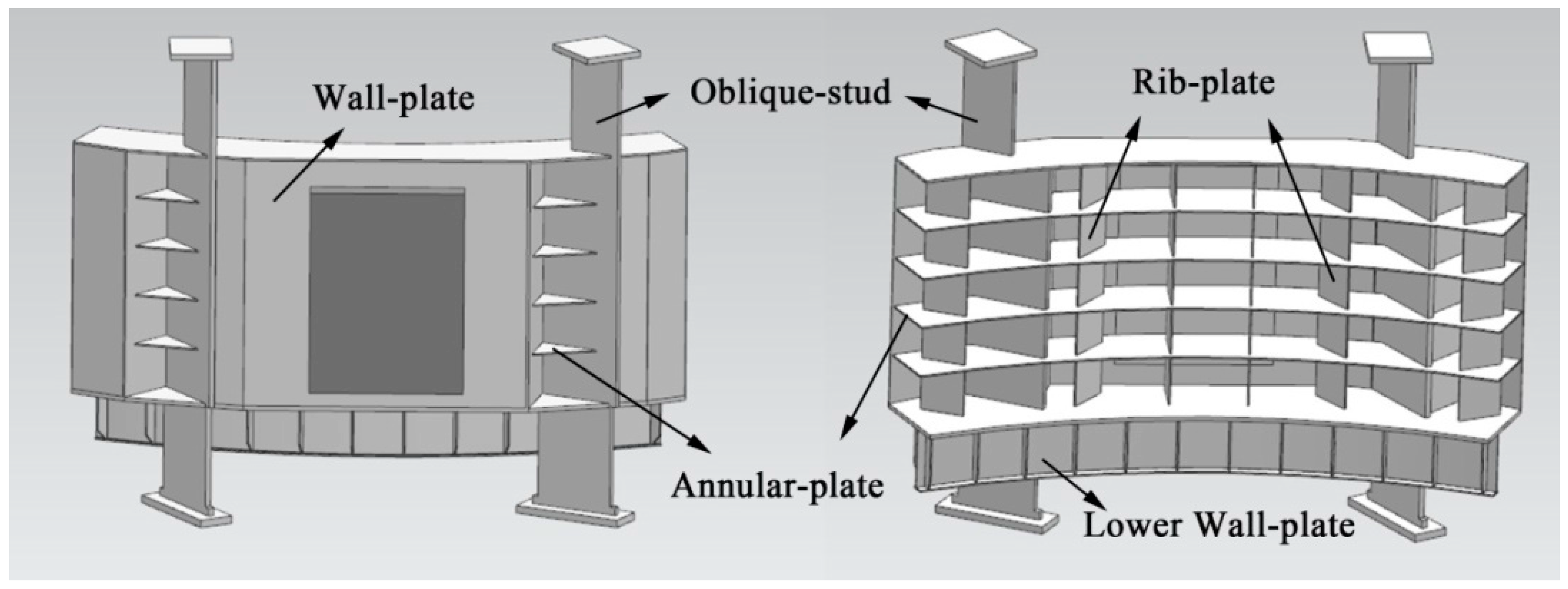
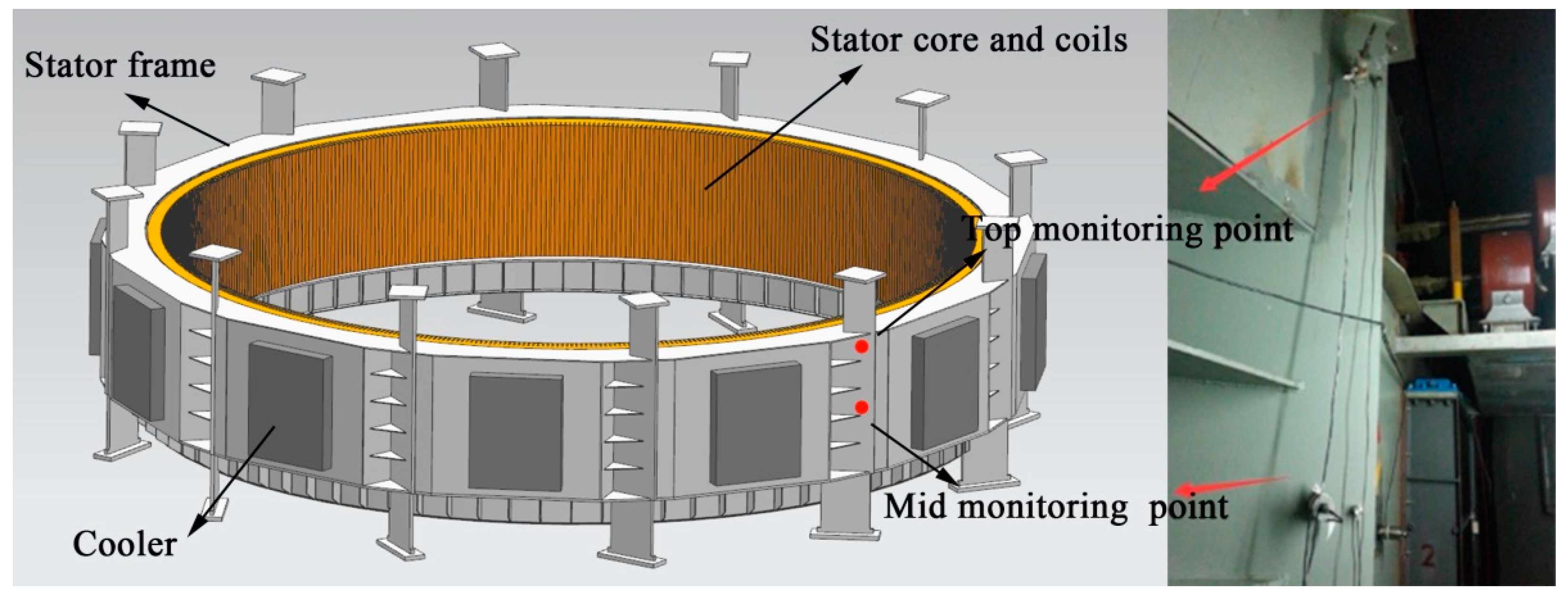
2.1. The Investigated Stator Frame
2.2. Three Sets of Experimental Tests
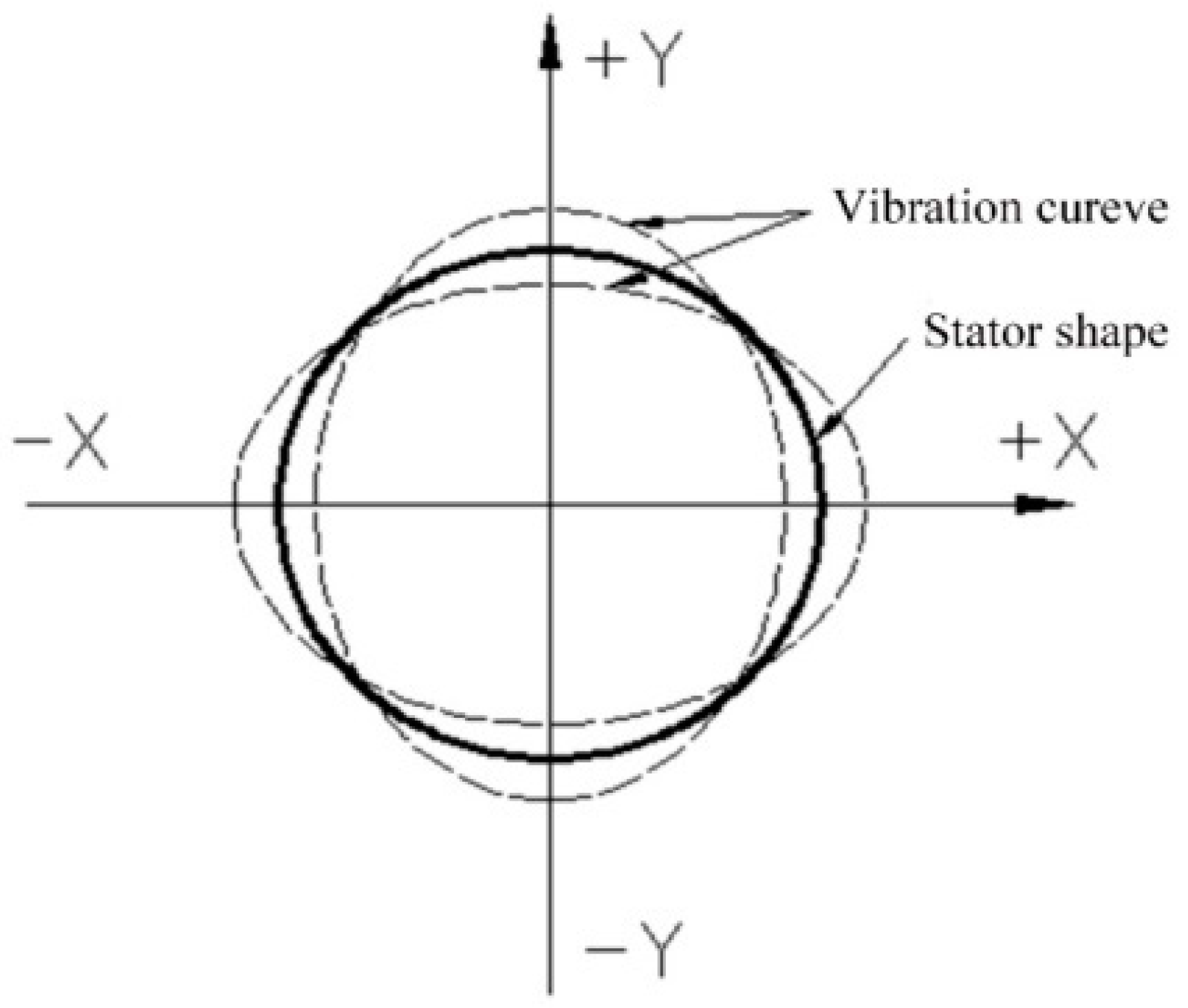
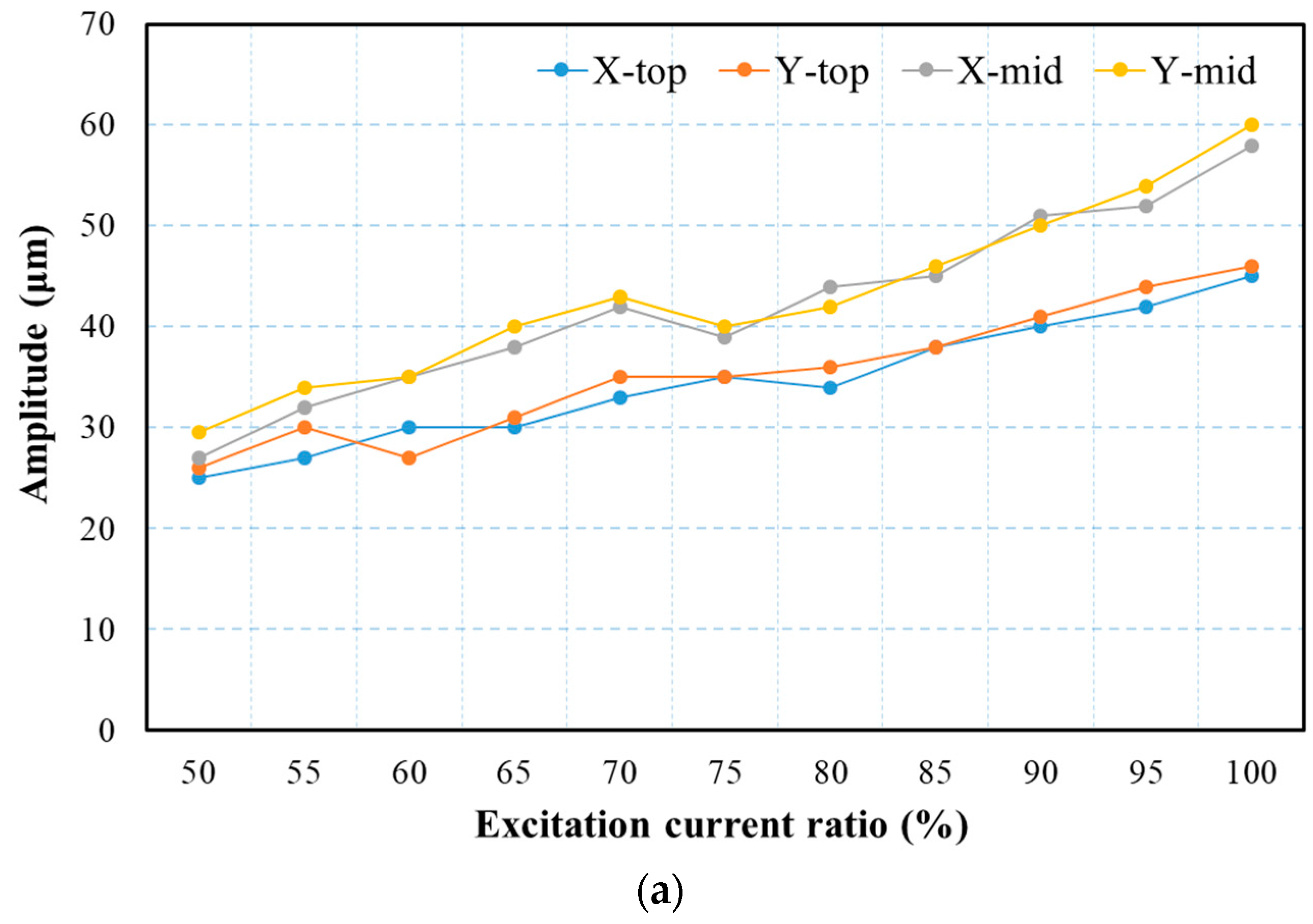
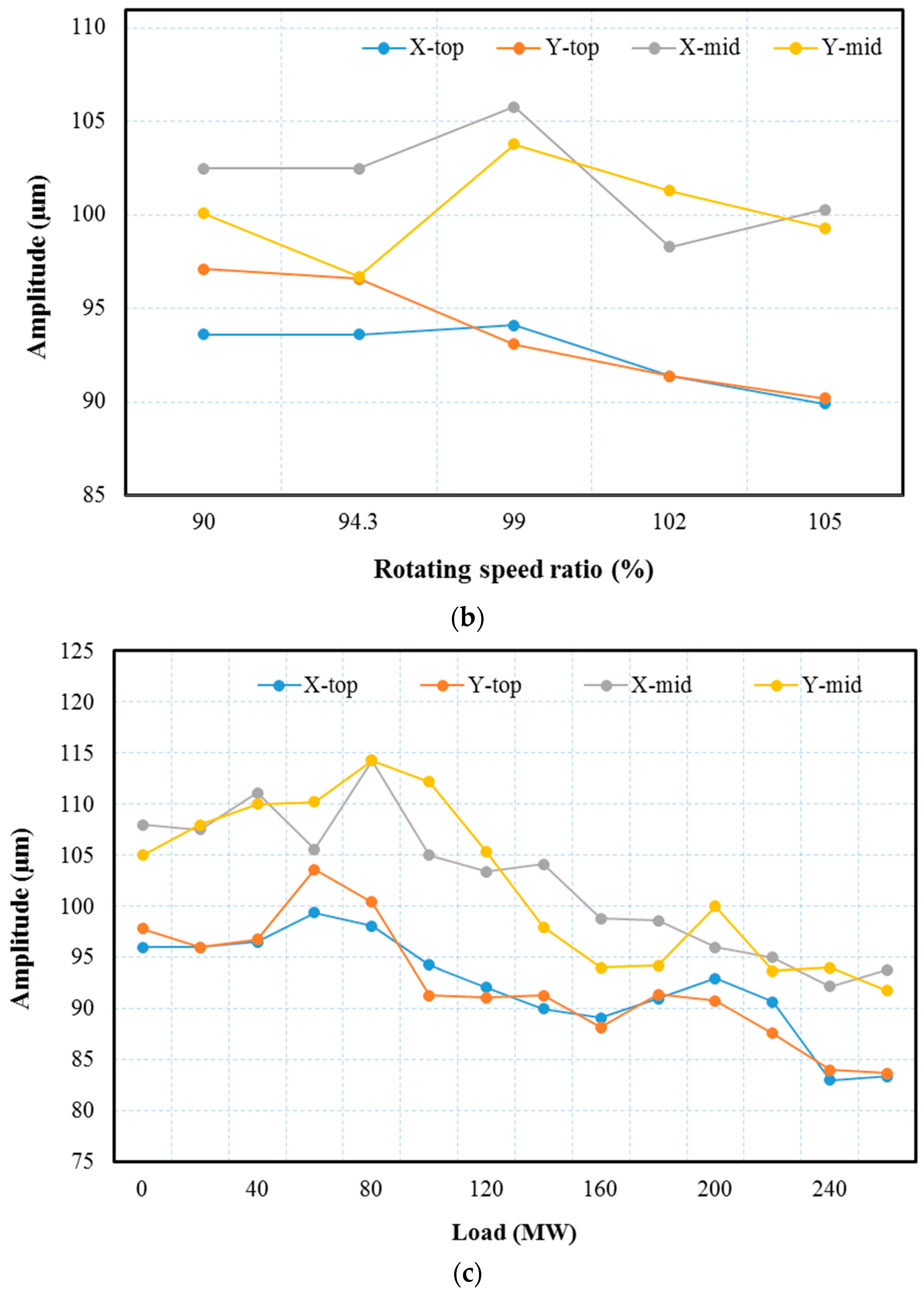
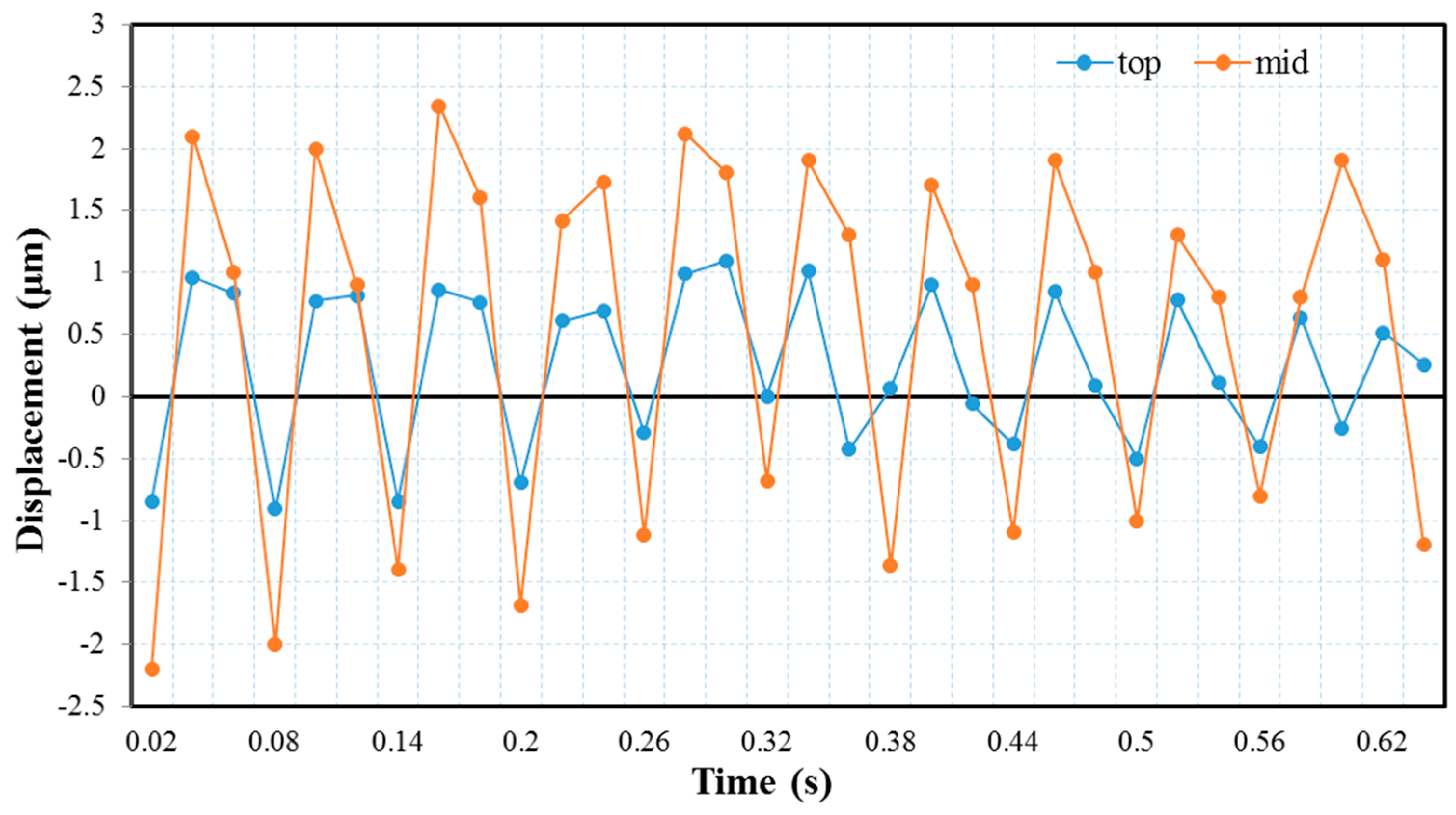
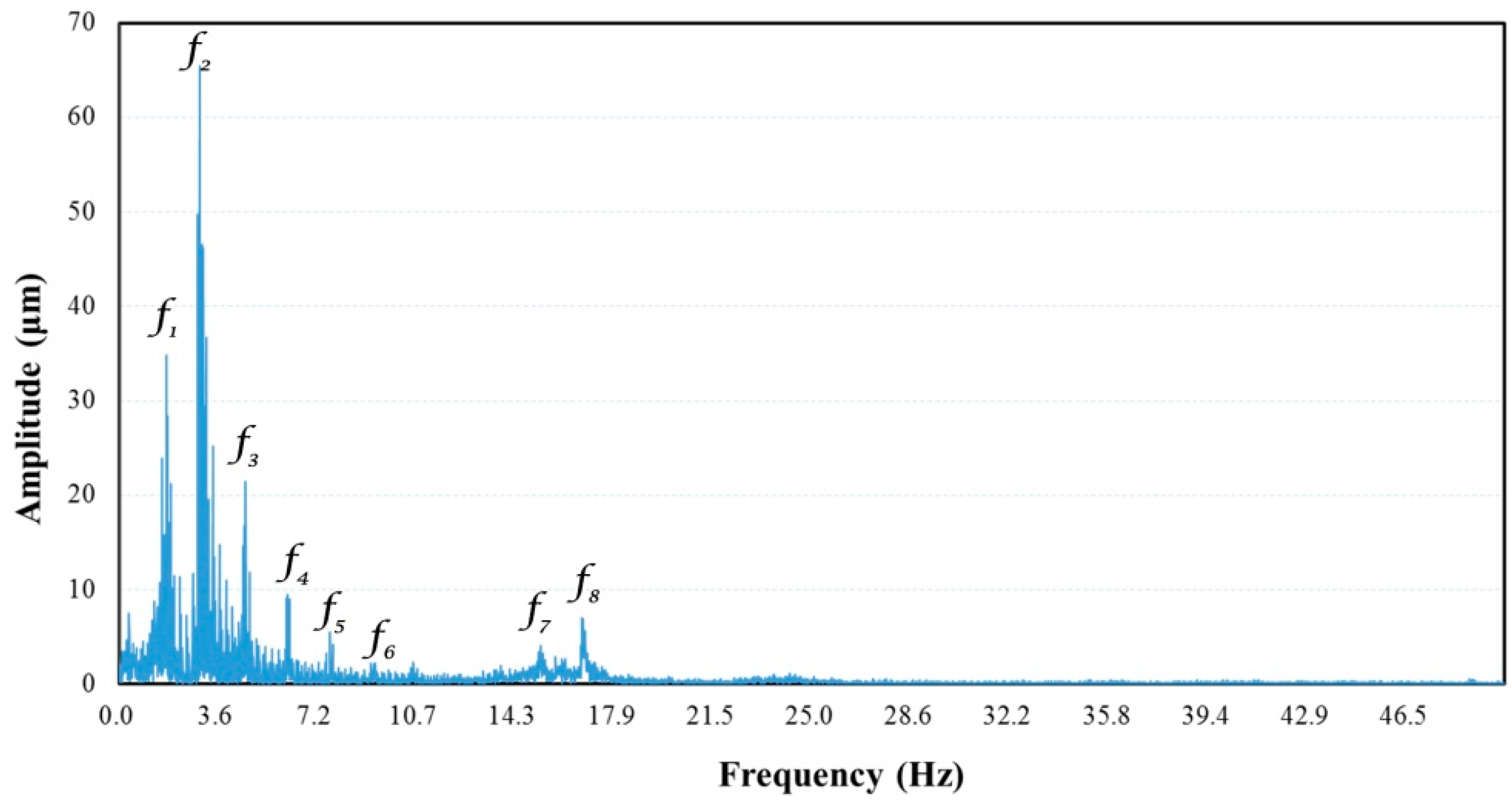
2.3. Results of the Experimental Tests
3. Finite Element Analysis
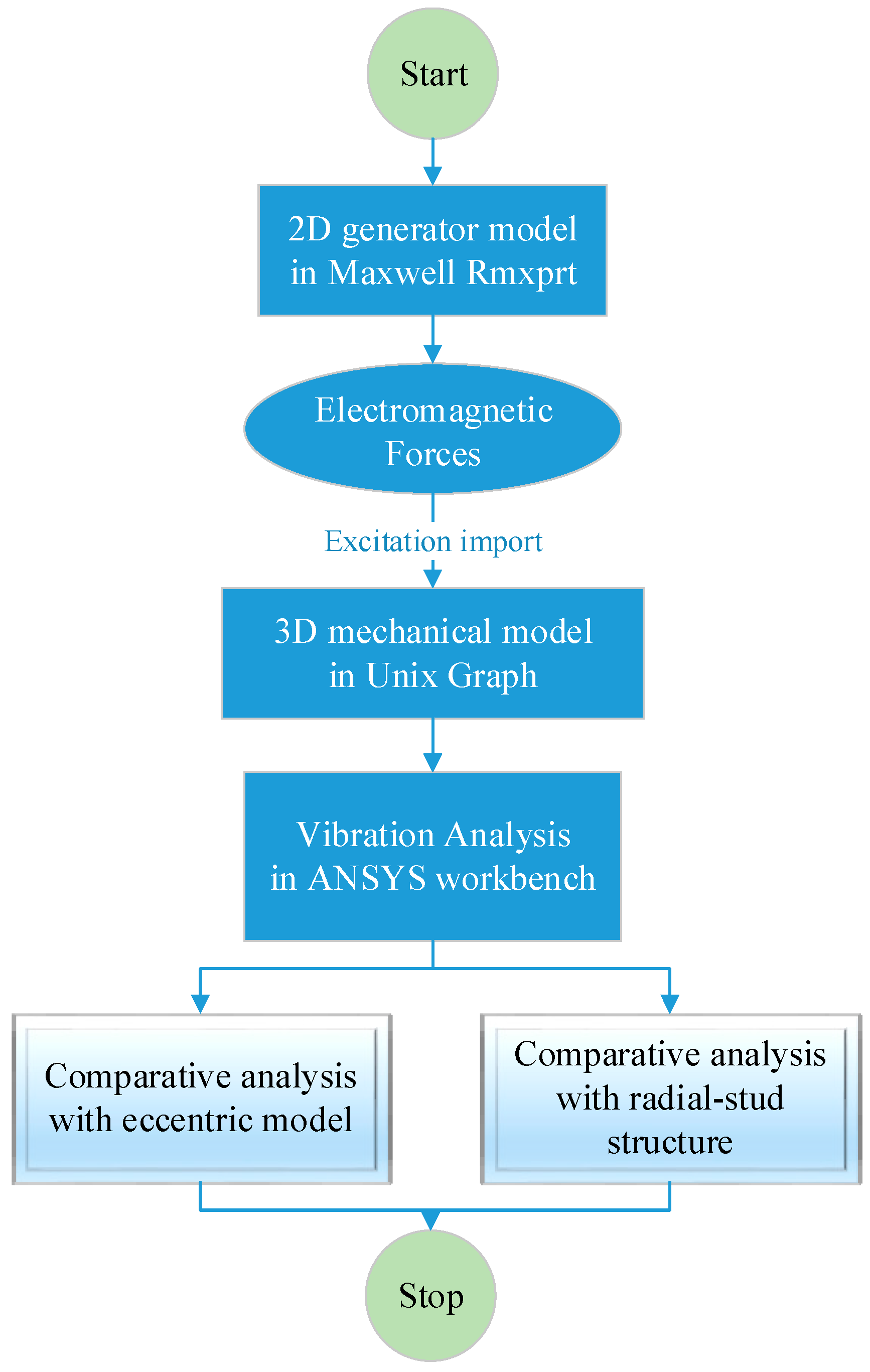
3.1. Methodology
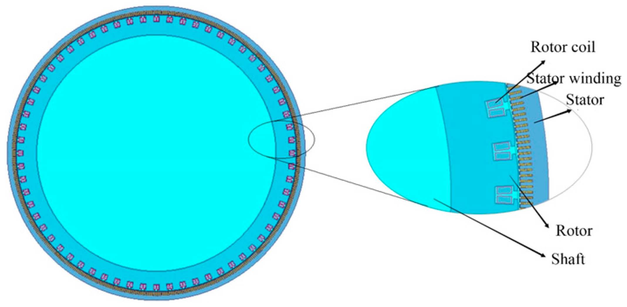
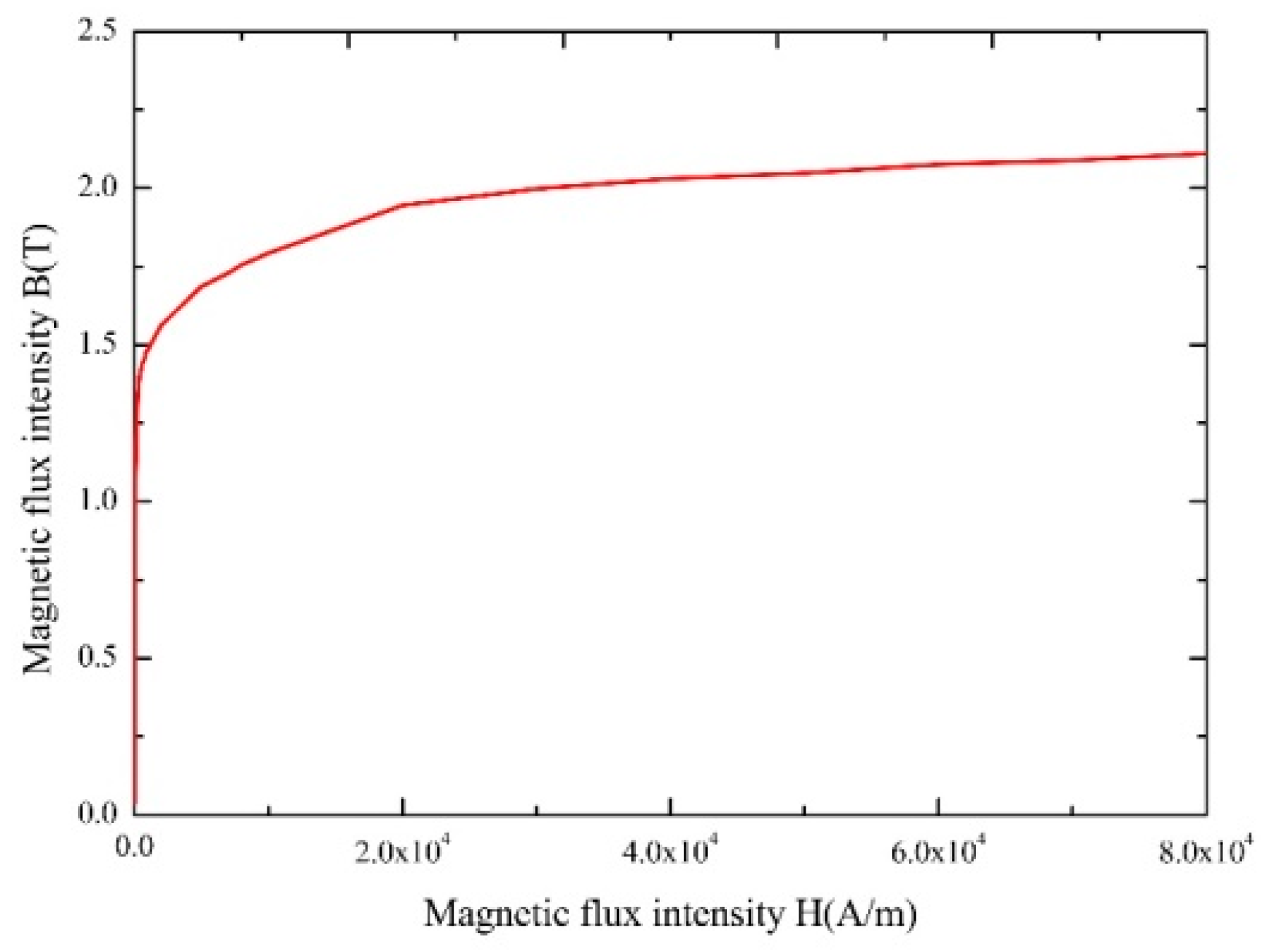
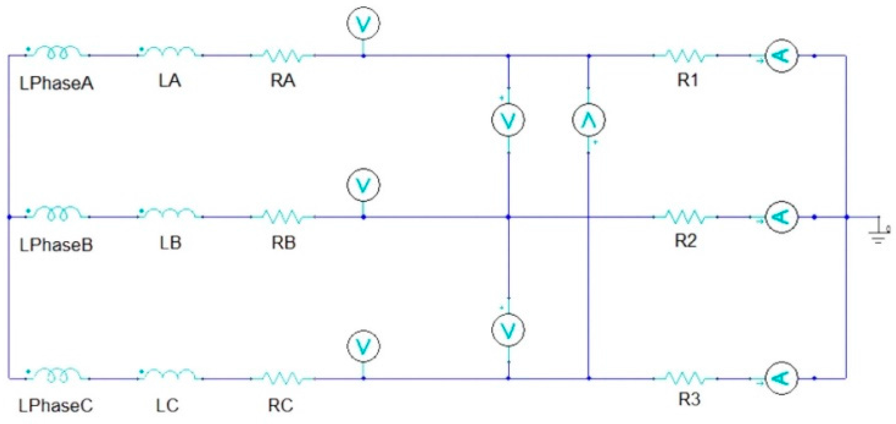
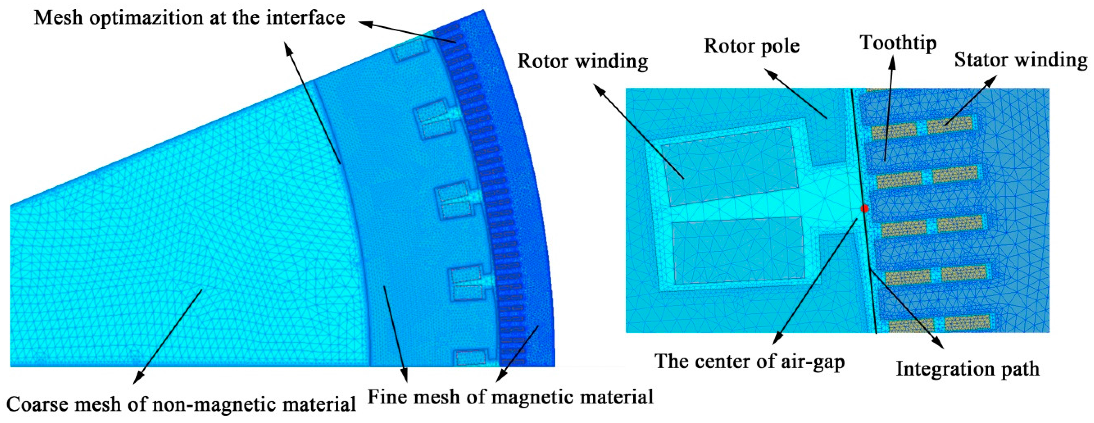
3.2. A 2D Generator Model for Electromagnetic Analysis
3.3. A 3D Stator Model for Mechanical Analysis
4. Comparative Analyses of Different Models
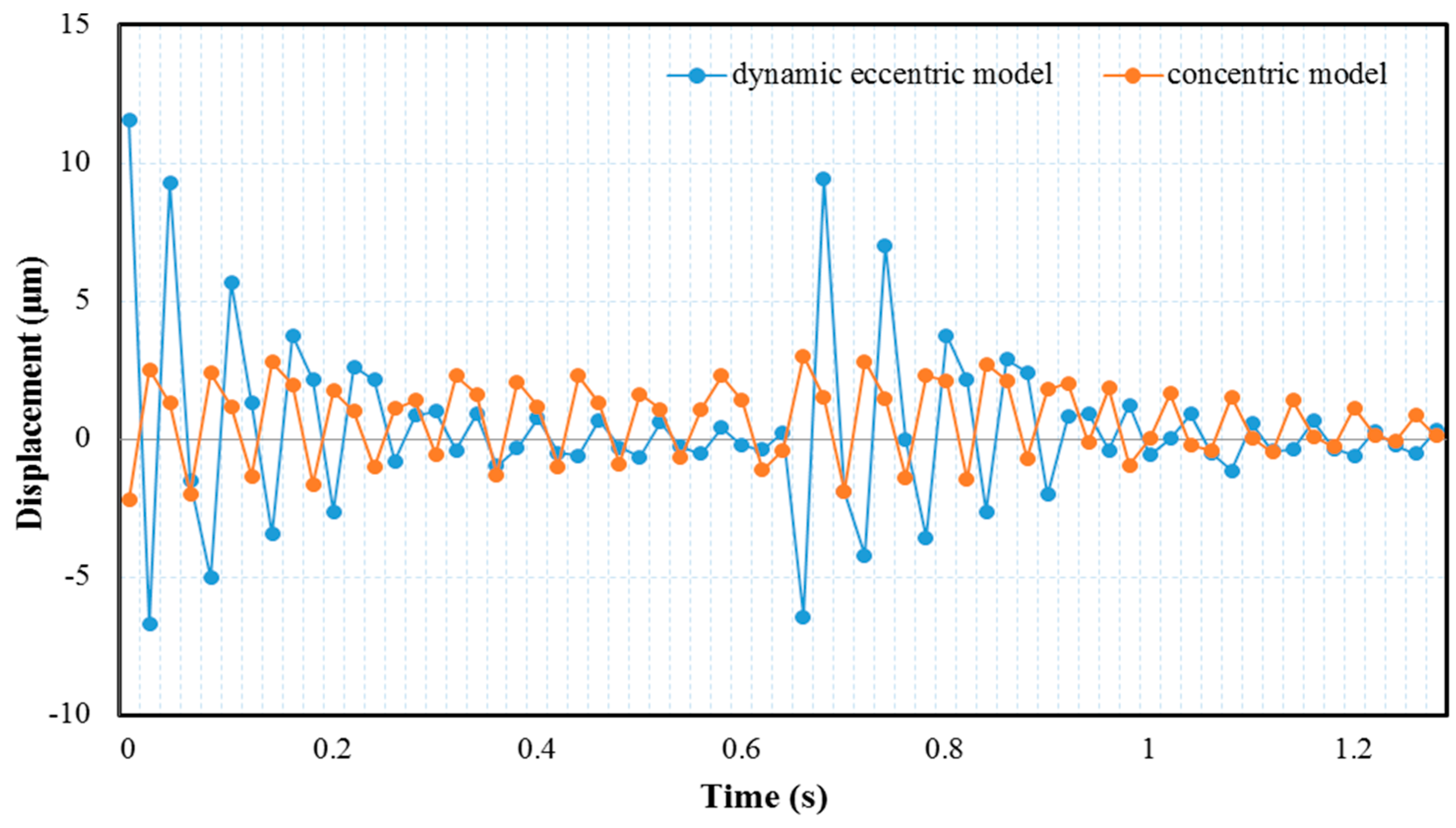
4.1. Eccentric Rotor–Stator Model
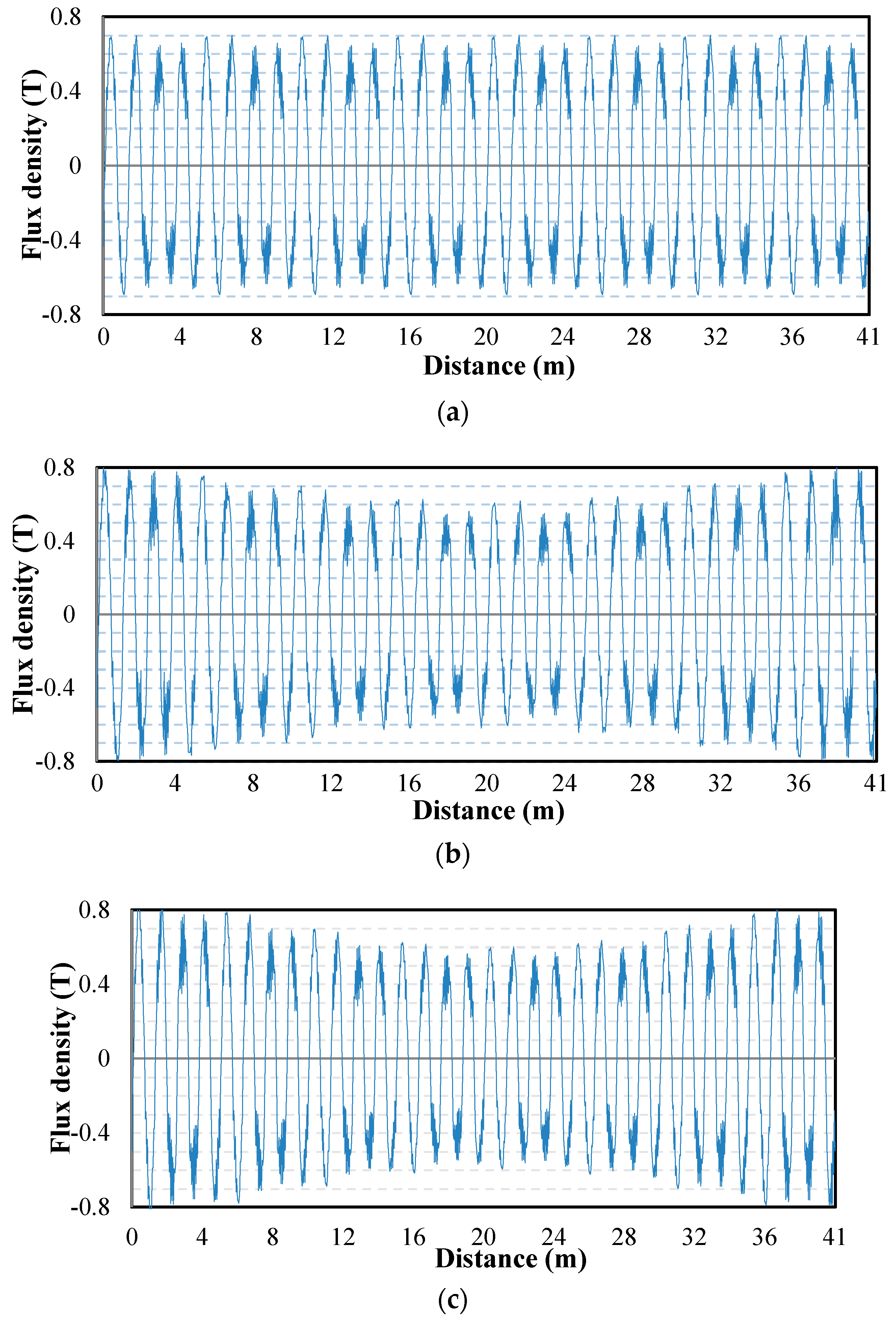
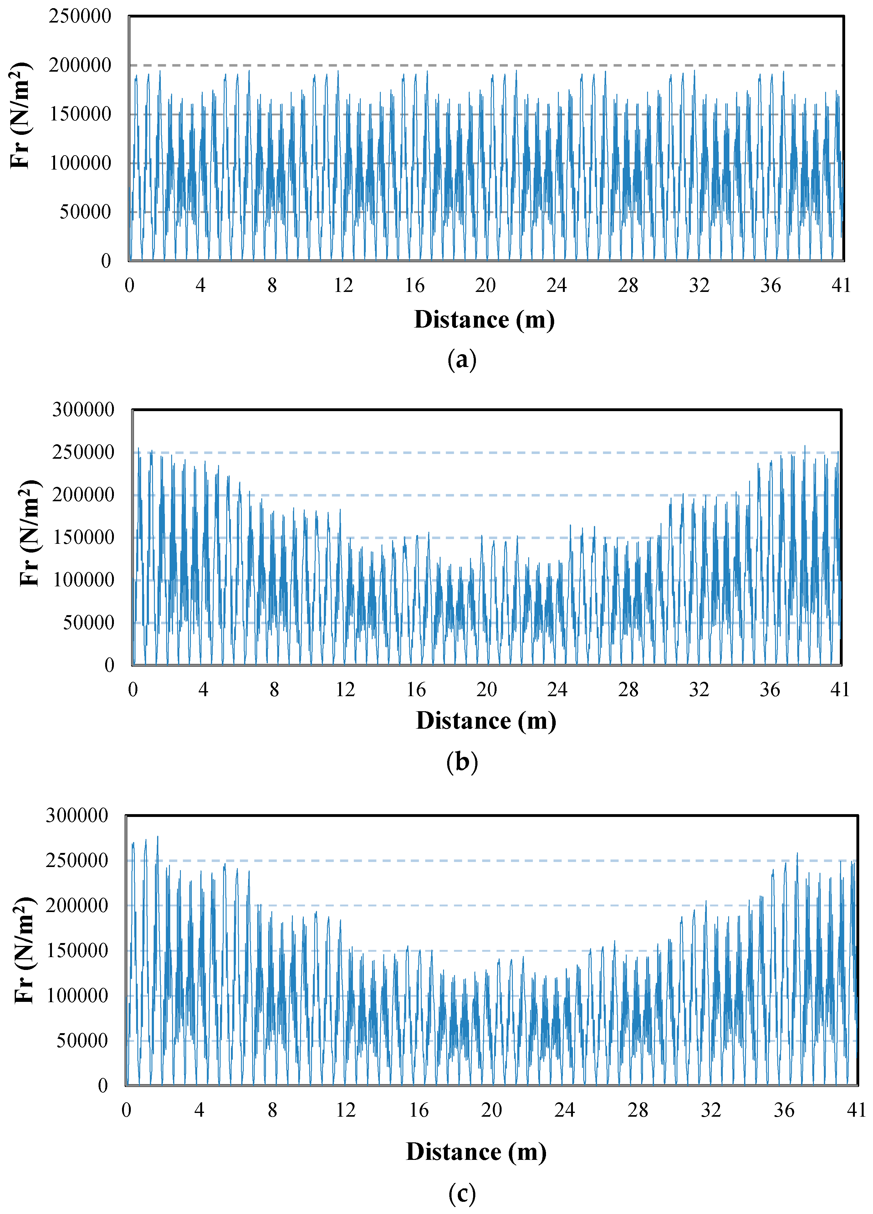
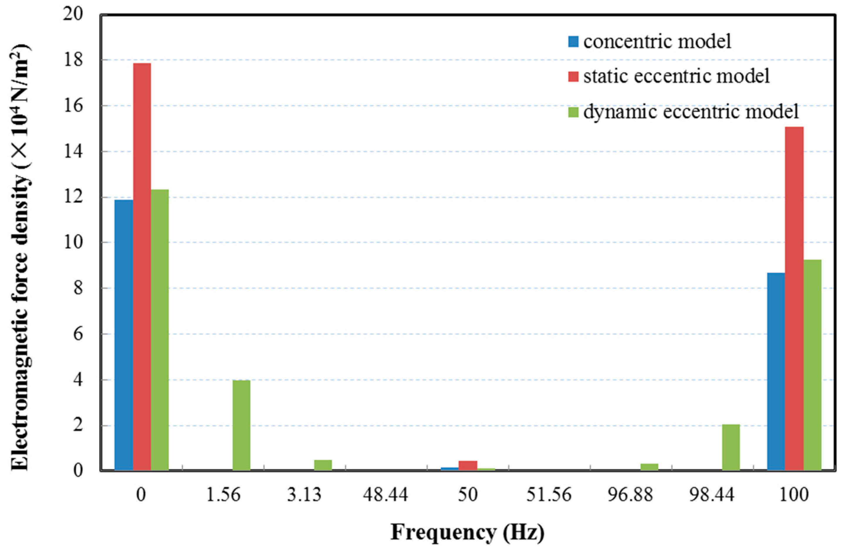
4.1.1. Electromagnetic Field Analysis
4.1.2. Transient Structure Analysis
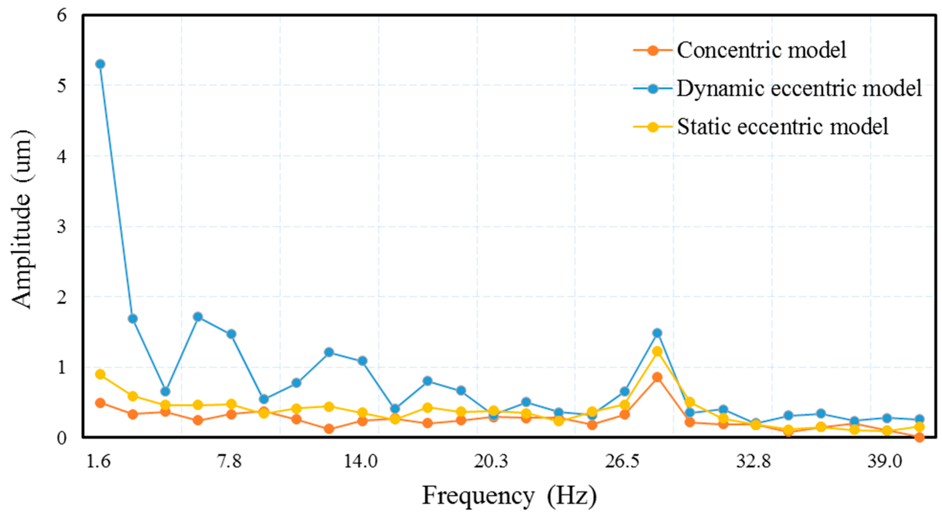
4.1.3. Harmonic Response Analysis
4.2. Structural Comparative Analysis
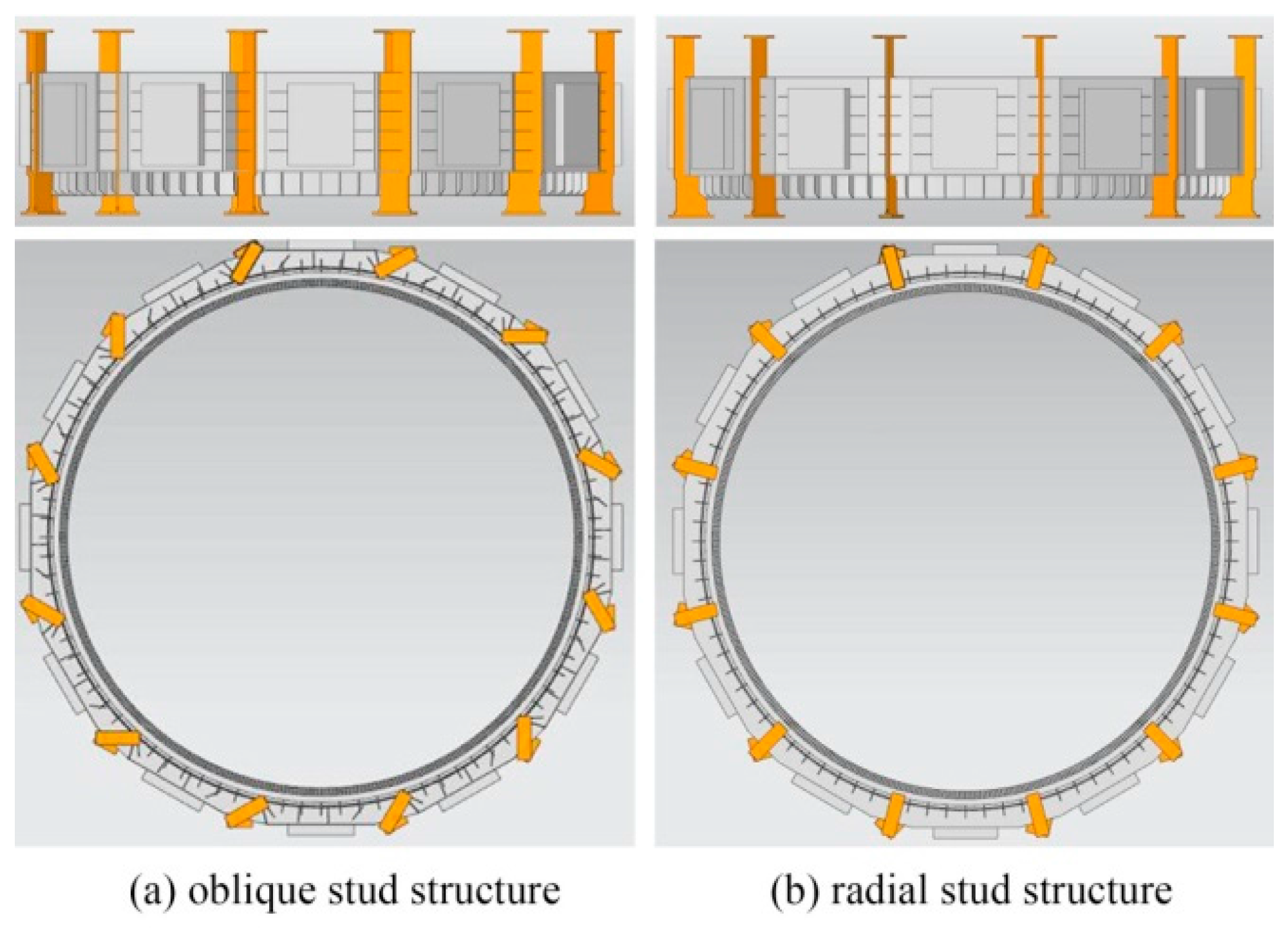
4.2.1. Simulation of Different Structures
4.2.2. Research of Different Structures
5. Conclusions
Acknowledgments
Author Contributions
Conflicts of Interest
References
- Martinez, J.; Belahcen, A.; Detoni, J.G. A 2D magnetic and 3D mechanical coupled finite element model for the study of the dynamic vibrations in the stator of induction motors. Mech. Syst. Signal Process. 2016, 66–67, 640–656. [Google Scholar] [CrossRef]
- Donát, M.; Dušek, D. Eccentrically mounted rotor pack and its influence on the vibration and noise of an asynchronous generator. J. Sound Vib. 2015, 344, 503–516. [Google Scholar] [CrossRef]
- Sathyan, S.; Belahcen, A.; Kataja, J.; Vaimann, T.; Sobra, J. Computation of Stator Vibration of an Induction Motor using Nodal Magnetic Forces. In Proceedings of the 2016 XXII International Conference on Electrical Machines, Lausanne, Switzerland, 4–7 September 2016. [Google Scholar]
- Bazan, G.H.; Scalassara, P.R. Stator fault analysis of three-phase induction motors using information measures and artificial neural networks. Electr. Power Syst. Res. 2017, 143, 347–356. [Google Scholar] [CrossRef]
- Glowacz, A.; Glowacz, W.; Glowacz, Z.; Kozik, J. Early fault diagnosis of bearing and stator faults of the single-phase induction motor using acoustic signals. Measurement. 2017, 113, 1–9. [Google Scholar] [CrossRef]
- Lashkari, N.; Poshtan, J.; Azgomi, H.F. Simulative and experimental investigation on stator winding turn and unbalanced supply voltage fault diagnosis in induction motors using Artificial Neural Networks. ISA Trans. 2015, 59, 334–342. [Google Scholar] [CrossRef] [PubMed]
- Dorrell, D.G.; Smith, A.C. Calculation of UMP in induction motors with series or parallel winding connections. IEEE Trans. Energy Convers. 1994, 9, 304–310. [Google Scholar] [CrossRef]
- Smith, A.C.; Dorrell, D.G. Calculation and measurement of unbalanced magnetic pull in cage induction motors with eccentric rotors. IEEE Proc. Electr. Power Appl. 1996, 143, 193–201. [Google Scholar] [CrossRef]
- Guo, D.; Chu, F.; Chen, D. The unbalanced magnetic pull and its effects on vibration in a three-phase generator with eccentric rotor. J. Sound Vib. 2002, 254, 297–312. [Google Scholar] [CrossRef]
- Fonteyn, K.; Belahcen, A.; Kouhia, R.; Rasilo, P.; Arkkio, A. FEM for Directly Coupled Magneto-Mechanical Phenomena in Electrical Machines. IEEE Trans. Magn. 2010, 46, 2923–2926. [Google Scholar] [CrossRef]
- Lin, R.; Arkkio, A. 3-D Finite Element Analysis of Magnetic Forces on Stator End-Windings of an Induction Machine. IEEE Trans. Magn. 2008, 44, 4045–4048. [Google Scholar]
- Xu, Y.; Li, Z. Computational Model for Investigating the Influence of Unbalanced Magnetic Pull on the Radial Vibration of Large Hydro-Turbine Generators. J. Vib. Acoust. 2012, 134. [Google Scholar] [CrossRef]
- Talas, P.; Toom, P. Dynamic Measurement and Analysis of Air Gap Variations in Large Hydroelectric Generators. IEEE Trans. Power Appar. Syst. 1989, PAS-102, 3098–3106. [Google Scholar] [CrossRef]
- Adamowski, J.C.; Souza, A.T.; Pérez, N.; Lima, A.A.; Oda, P.D.; Tiba, H.H. Ultrasonic dynamic air-gap monitoring system for large hydro-generators. In Proceedings of the 2013 IEEE International Ultrasonics Symposium, Prague, Czech Republic, 21–25 July 2013. [Google Scholar]


| Parameter | Value |
|---|---|
| Radius of rotor (mm) | 6430 |
| Outer diameter of stator (mm) | 13,700 |
| Inner diameter of stator (mm) | 12,900 |
| Height of stator core (mm) | 2340 |
| No. of parallel branches of stator winding | 4 |
| No. of stator’s slots | 528 |
| No. of poles | 64 |
| Rotate speed (r/min) | 93.75 |
| Item | Simulation | Experiment | Error |
|---|---|---|---|
| Peak of line voltage | 21.87 kV | - | - |
| Peak of line current | 14.72 kA | - | - |
| Voltage | 15.44 kV | 15.76 kV | 2.0% |
| Current | 10.41 kA | 10.1826 kA | 2.2% |
| Power | 250.6 MW | 250.1 MW | 0.33% |
| Item | Material | ρ (kg/m−3) | E (× Pa) | μ (-) |
|---|---|---|---|---|
| Stator core | Silicon steel 50W250 | 7650 | 1.9 | 0.28 |
| Coils | Red Cooper | 3580 | 1.5 | 0.34 |
| Stator frame | Steel Q235A | 7850 | 2.1 | 0.3 |
| Cooler | Aluminum alloy | 2770 | 0.71 | 0.33 |
| Mode | Natural Frequency | Description |
|---|---|---|
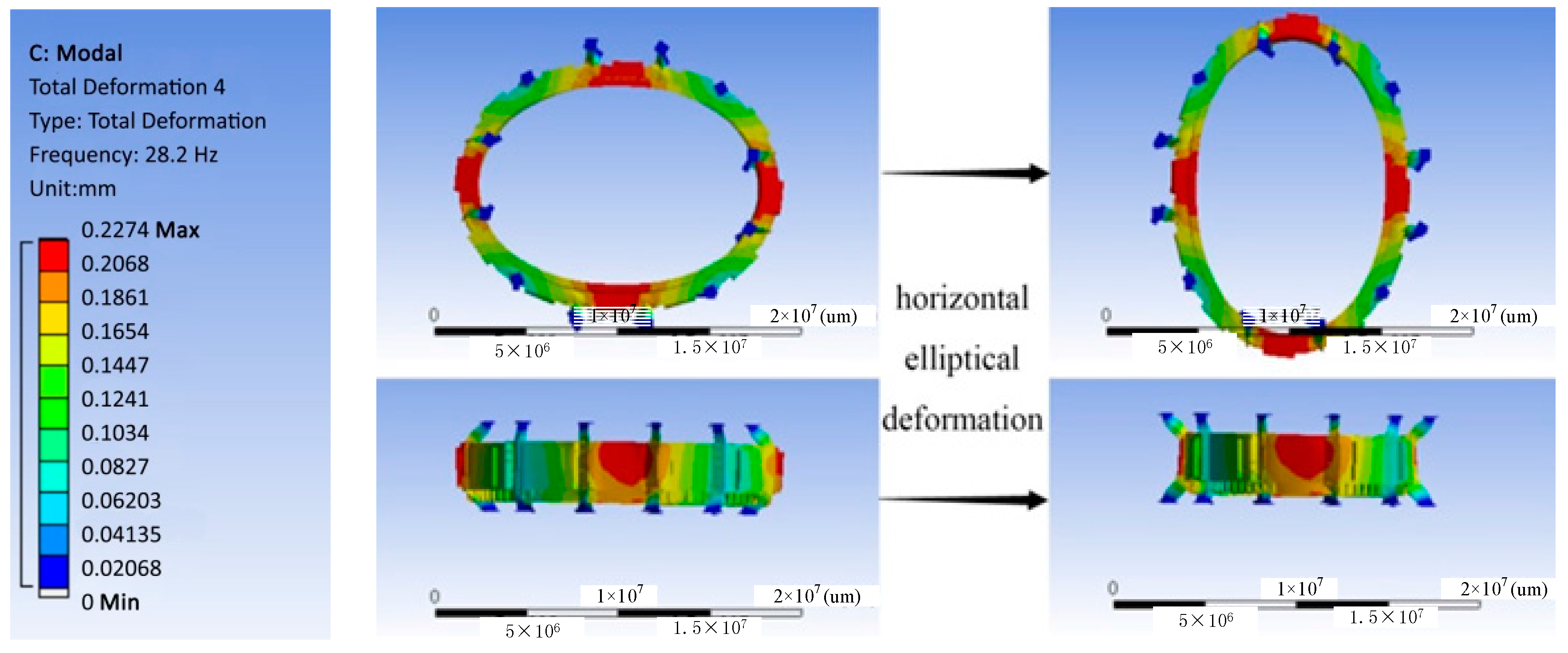
| 1 | 28.2 Hz | Horizontal elliptical deformation |
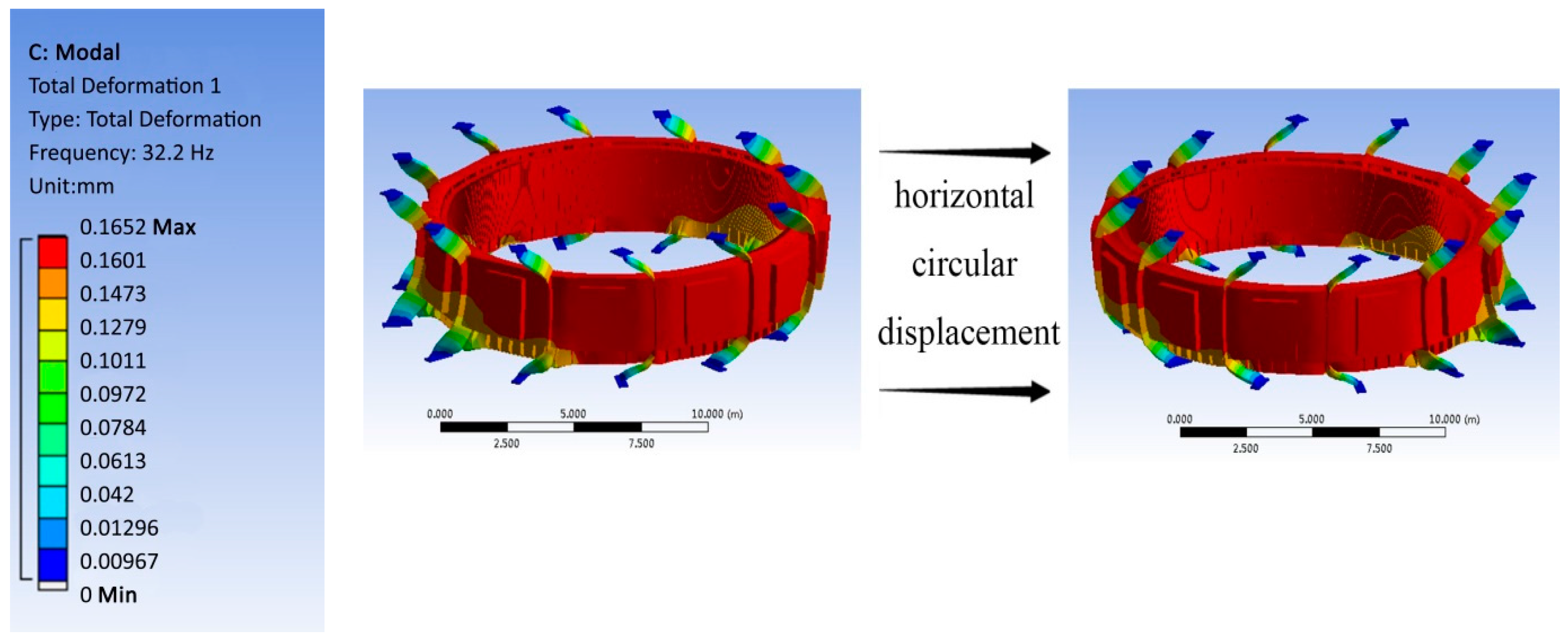
| 2 | 29.6 Hz | Horizontal circular displacement |
| 3 | 41.4 Hz | Horizontal triangular tensile deformation |
| 4 | 52.1 Hz | Horizontal quadrangular tensile deformation |
| Item | The Studied Stator Frame | Contrast Model |
|---|---|---|
| Structures | Oblique-stud structure | Radial-stud structure |
| Characteristic | flexible | rigid |
| Natural frequency of 1st mode | 28.2 Hz | 32.2 Hz |
| Description of 1st mode shape | Horizontal elliptical deformation | Horizontal circular displacement |
| Maximum amplitude | 2.1 µm | 1.4 µm |
| Station | No. of Unit | Capacity (MW) | Vibration Amplitude (µm) | Type |
|---|---|---|---|---|
| Three Gorges | 15 | 700 | 18 | rigid |
| 24 | 700 | 50 | flexible | |
| Laxiwa | 1 | 700 | 120 | flexible |
| Goupitan | 3 | 600 | 60 | rigid |
| 4 | 600 | 200 | flexible | |
| pubugou | 1 | 600 | 6 | rigid |
| 4 | 600 | 28 | rigid |
© 2017 by the authors. Licensee MDPI, Basel, Switzerland. This article is an open access article distributed under the terms and conditions of the Creative Commons Attribution (CC BY) license (http://creativecommons.org/licenses/by/4.0/).
Share and Cite
Zhou, J.; Peng, X.; Li, R.; Xu, Y.; Liu, H.; Chen, D. Experimental and Finite Element Analysis to Investigate the Vibration of Oblique-Stud Stator Frame in a Large Hydropower Generator Unit. Energies 2017, 10, 2175. https://doi.org/10.3390/en10122175
Zhou J, Peng X, Li R, Xu Y, Liu H, Chen D. Experimental and Finite Element Analysis to Investigate the Vibration of Oblique-Stud Stator Frame in a Large Hydropower Generator Unit. Energies. 2017; 10(12):2175. https://doi.org/10.3390/en10122175
Chicago/Turabian StyleZhou, Jianzhong, Xuanlin Peng, Ruhai Li, Yanhe Xu, Han Liu, and Diyi Chen. 2017. "Experimental and Finite Element Analysis to Investigate the Vibration of Oblique-Stud Stator Frame in a Large Hydropower Generator Unit" Energies 10, no. 12: 2175. https://doi.org/10.3390/en10122175
APA StyleZhou, J., Peng, X., Li, R., Xu, Y., Liu, H., & Chen, D. (2017). Experimental and Finite Element Analysis to Investigate the Vibration of Oblique-Stud Stator Frame in a Large Hydropower Generator Unit. Energies, 10(12), 2175. https://doi.org/10.3390/en10122175