Abstract
The purpose of this research is to develop a new torque vectoring differential (TVD) for vehicle applications and investigate its effect on vehicle dynamic control. TVD is a technology that is able to distribute the engine torque to the left and right driving wheels at different ratios so that the yaw motion control can be realized. Attention has been paid to this technology in recent years because of its potential to improve the vehicle performance and driving safety. In this study, a new TVD design with a Ravigneaux gearset was developed. This new design is able to use only one pair of gearsets to generate two different speed ratios, and the weight and volume of the system can be reduced. To execute the research, current TVD designs were analyzed and their design principles were clarified. Next, a new TVD design with Ravigneaux gearset was proposed. Then the connecting manner and the gear ratio of the Ravigneaux gearset were discussed. The dynamic equation of the system was then derived and the operation of the system was simulated in a MATLAB program. Further simulation was performed with a vehicle dynamic model in SimulationX to demonstrate the effect of the new system. The results of this study show the potential of building a new TVD with a Ravigneaux gearset and can be helpful for further system development.
1. Introduction
Vehicle dynamic control is an essential task for improving driving performance and vehicle safety. Different control strategies such as direct yaw-moment control (DYC) have been proposed and well-discussed in the past [1,2]. Various systems, e.g., electronic stability program (ESP) [3], four-wheel steering (4WS) [4] have been developed to realize vehicle dynamic control in practical applications. Torque vectoring is a new technology that has been drawing the attention of the car industry in recent years. It is employed in automobile differentials and is able to distribute different driving torque values to different wheels so that traction distribution can be realized. Because of the operation of transferring the torque instead of diminishing the torque on the wheels, better system efficiency can be achieved. The torque vectoring technology becomes more competitive than the brake-based systems.
Different torque vectoring differential (TVD) patents have been revealed by car companies and suppliers, such as Ford, ZF, and Honda recently [5,6,7,8,9]. Most general designs consist of two pairs of gearsets in different speed ratios, and utilize clutches, brakes, or motors to control the direction of the transferred wheel torque [10,11,12,13,14]. However, the two pairs of gearsets or motors in current designs result in heavier system weight and larger space requirements. In this paper, a new TVD design with Ravigneaux gearset is proposed. This design is able to use only one pair of gearsets to generate two different speed ratios, and the weight and volume of the system can be reduced.
The research process of this study is described as follows. Firstly, the current TVD designs are analyzed and their design principle is understood. A new TVD design with Ravigneaux gearset is proposed. Then the connecting manner and gear ratio of the Ravigneaux gearset is discussed. The dynamic equation of the system is then derived and the operation of the system is simulated in a MATLAB program (The MathWorks, Inc., Natick, MA, USA). Further simulation is performed with vehicle dynamic model in SimulationX (ESI ITI GmbH, Dresden, Germany) to demonstrate the effect of the new system to vehicle dynamics. The results of this study are summarized in the conclusions.
2. Current Torque Vectoring Differential
Two current TVD designs are under investigation in this section to understand the design principles of the systems. The schematic diagrams of the superposition-clutch TVD (SPC-TVD) and the stationary-clutch TVD (STC-TVD) [15] are illustrated in Figure 1, and their system configurations transferred by means of a function power graph (FPG) [16] are shown in Figure 2. In Figure 1 and Figure 2, DG denotes the differential gearset; W1 and W2 are the left and right wheels; C1 and C2 are clutches; B1 and B2 are brakes; G, G0, G1 and G2 are gear pairs; PG1 and PG2 are planetary gearsets; IN is the input of the engine power.
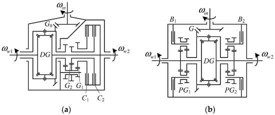
Figure 1.
Schematic diagrams of current torque vectoring differential (TVD) designs: (a) superposition-clutch (SPC)-TVD and (b) stationary-clutch (STC)-TVD [15].
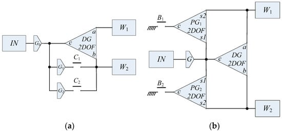
Figure 2.
System configurations of current TVD designs: (a) SPC-TVD and (b) STC-TVD.
In Figure 2, the SPC-TVD consists of two gear pairs (G1 and G2), and two clutches (C1 and C2). When C1 is engaged, the speed ratio of the left and right wheels is decided by the gear ratio of G1. Similarly, when C2 is engaged, the speed ratio of the two wheels is decided by the gear ratio of G2. With the different gear ratios of G1 and G2, tire slip ratio of the two tires can be controlled with different engagements of the clutches, so that different traction distributions can be achieved and the torque vectoring effect can be realized.
A similar operation principle is also observed from the STC-TVD design, in which two planetary gearsets PG1 and PG2 are involved, and two brakes B1 and B2 are used to select the direction of the torque vectoring effect. When B1 is engaged, the speed ratio of the left and right wheels is decided by the gear ratio of PG1. On the other hand, when B2 is engaged, the speed ratio of the two wheels is decided by the gear ratio of PG2.
According to the two current TVD designs discussed above, a TVD can be developed when two gear ratios between the left and right wheels are achievable, and the two ratios can be selected by controlling the engagement of the clutches or brakes. This is the design principle of the TVD understood by the authors and will be used for further TVD development in the later part of this study.
3. Design of New Torque Vectoring Differential
It is found that the STC-TVD uses two planetary gearsets in order to acquire the two different speed ratios between the two wheels. However, this may cause the system to require more space and have a heavier weight. Since the Ravigneaux gearset can reduce one ring gear compared to the two planetary gearsets design, there is a potential to reduce the space and weight of the STC-TVD design. Therefore, the authors of this study propose a new TVD design which involves a Ravigneaux gearset, and the new system is named Ravigneaux TVD (Rav-TVD) in this research.
Here, the feasible configuration of a Rav-TVD is discussed. The Ravigneaux gearset is a two degrees-of-freedom (DoF) mechanism which has four links, i.e., ring gear, carrier, large sun gear, and small sun gear, to connect to other devices. The twelve possible configurations of a Rav-TVD are listed in Table 1. In order to achieve the torque vectoring effect, the two brakes B1 and B2 have different effects on the speed relation between the input IN and the wheel W1. This means when the B1 engagement makes the input IN rotate faster than the wheel W1, then the B2 engagement should make IN rotate slower than W1. According to Table 1, configurations 1, 2, 4, and 6 satisfy this requirement and can be developed as a TVD. Since the gear ratio of the Ravigneaux gearset in configuration 2 is the most practical in realistic applications, configuration 2 is considered to be the most feasible configuration for a Rav-TVD, and was further investigated in this study.

Table 1.
Possible arrangements of a Ravigneaux TVD (Rav-TVD).
The configuration of the Rav-TVD is shown in Figure 3a and its schematic diagram is shown in Figure 3b. The Ravigneaux gearset is denoted as a square in the sketch of system configuration, and the four corners of the square are marked with the corresponding gears. The r is the ring gear, c is the carrier, ss is the small sun gear, and sl is the large sun gear. The Rav-TVD connects the ring gear to the input and differential carrier. The large sun gear is connected to wheel W1 and one of the differential shafts. The small sun gear and the carrier of the Ravigneaux gearset are connected to brakes individually so that different torque vectoring effects can be controlled by the engagement of the brakes.
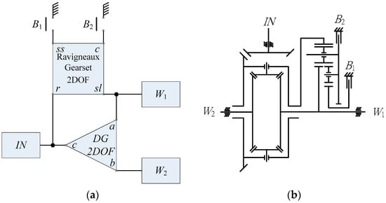
Figure 3.
(a) System configuration and (b) Schematic diagram of the Rav-TVD.
The speed relation between each gear in the Ravigneaux gearset can be visualized in the lever diagram as shown in Figure 4, and can be calculated via Equations (1) and (2) [17,18], in which ωr, ωc, ωsl, and ωss are the rotating speed of the ring gear, carrier, large sun gear, and small sun gear, respectively. iss is the gear ratio between the ring gear and the small sun gear, as presented in Equation (3), and isl is the gear ratio between the ring gear and the large sun gear, as shown in Equation (4), where Zr, Zss and Zsl are the number of teeth on the ring gear, small sun gear, and large sun gear respectively. The constraint of iss and isl is indicated in Equation (5).
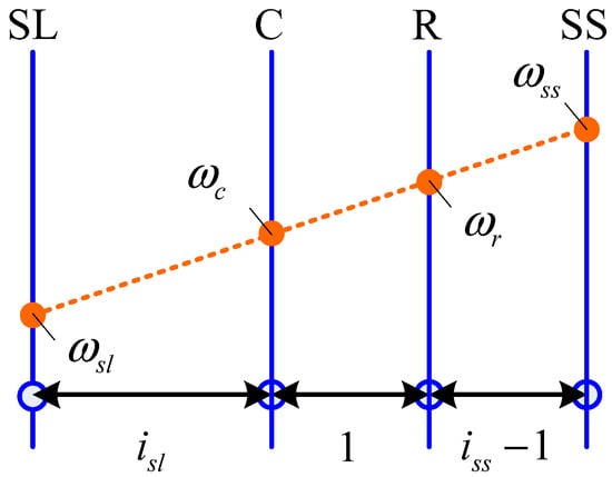
Figure 4.
Lever diagram of a Ravigneaux gearset.
To operate the Rav-TVD, when the brake B1 is engaged, a braking force will be applied to the small sun gear and reduce its speed; according to the lever diagram, this operation results in a trend such that the speed of the large sun gear (wheel W1) will be faster than the ring gear (Input IN), and hence the wheel W1 will rotate faster than the wheel W2. On the other hand, when the brake B2 is engaged, a braking force will be applied to the carrier, and the speed of the large sun gear (wheel W1) will be slower than the ring gear (Input IN). Thus, the wheel W1 will rotate slower than the wheel W2. With the opposite speed trends between the two wheels controlled by the two brakes, the torque vectoring effect can be realized by the Rav-TVD.
4. Modeling
The dynamic equation of the Rav-TVD is a combination of the dynamic equations of a Ravigneaux gearset and a conventional differential. The dynamic equation of a Ravigneaux gearset is shown in Equation (6), where I is the inertia, R the radius, the rotational acceleration, T the applied torque of each gear in the Ravigneaux gearset, and F1 and F2 respectively are the internal forces between the ring gear and the planet gears, and between the planet gears and the large and small sun gears. To establish the Rav-TVD model, parameters in Equation (6) were replaced with the parameters of the Rav-TVD system according to the connection relation introduced in the previous section. The dynamic model of the Rav-TVD is shown in Equation (7).
To have a preliminary insight of the system, a simulation program was developed based on Equation (7) and written in the MATLAB program to demonstrate the operation of the Rav-TVD. In the simulation, the torque on the input shaft Tin and the two wheels Tw1 and Tw2 are set to be constant. The braking torque Tb1 or Tb2 are initially zero and will be applied to the system at 1–2 s. The speed of the input shaft, the two wheels and the two brake discs were recorded. The parameters of this simulation are arranged in Table 2.
Table 2.
Parameters of the MATLAB simulation.
The results of the MATLAB simulation are shown in Figure 5. Figure 5a is the case when B1 is engaged at 1–2 s and B2 is not activated. When B1 is engaging, the wheel speed of W1 becomes faster than W2 and the speed difference constantly increases when B1 is activated. Figure 5b shows the case when B2 is engaged at 1–2 s when B1 is not activated. In this case, an opposite situation happens for the two wheels’ speeds, and W1 becomes slower than W2. According to these results, the proposed Rav-TVD can control the speed ratio between the two wheels symmetrically with different engagement of the brakes, and the design requirement of a TVD mentioned previously is fulfilled.
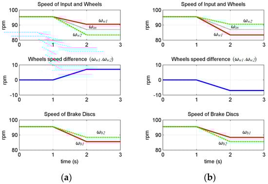
Figure 5.
Operation of the Rav-TVD while (a) B1 is engaged and (b) B2 is engaged.
5. Simulation Results
In this section, to demonstrate the torque vectoring effect of TVDs and its influence while turning in vehicle applications, the SPC-TVD and the Rav-TVD systems were built and applied to a vehicle dynamic model that was compared with a solid axle (SA) and an open differential (OD) in the simulation software called SimulationX. SimulationX is software provides a modeling platform and libraries with customizable elements and tools which can be used for system development and analysis, and it is one of the most popular software in the field of multi-physics modeling and simulation. In automotive technology, for examples, transmission elements (e.g., clutches [19,20,21], continuously variable transmissions [22,23]), hydraulic systems [24,25,26,27], powertrain drivelines [28,29,30], and hybrid transmissions [31,32,33] etc. have been surveyed and modeled based on SimulationX. In addition to computer-aided engineering (CAE) analysis, computer aided design (CAD) with three-dimensional (3D) solid modeling for vehicles has also been established [34,35].
Figure 6 shows the interface of SimulationX and a vehicle dynamic model with a steering control for front wheels, and an OD for rear wheels. In the diagram view of our model, connection lines can be categorized into three types: (a) Signal Blocks (blue lines for control signals), (b) 1D Mechanics (black lines for power transmission), and (c) Multi-Body System Mechanics (yellow lines for 3D vehicle that can be visualized in the 3D view). Due to the convenience of the SimulationX-based model, only the transmission part needs to be altered. For example, a vehicle dynamic model for a SA can be established easily by directly removing the differential element. In this simulation, the vehicle dynamics of the same vehicle equipped with different transmissions (SA, OD, SPC-TVD, and Rav-TVD) are investigated, where the vehicle is assumed be to a rear-wheel-drive vehicle. The simulation scenario is that the vehicle is driven, starting from 0 km/h at −6 s (time = −6 s) at first and accelerated to a constant speed at 60 km/h before 0 s (time < 0 s). Then, a P controller (Proportional controller) is used to maintain the vehicle speed at 60 km/h during the entire process (time > 0 s). More detailed numerical data is shown in Table A1 of Appendix A.
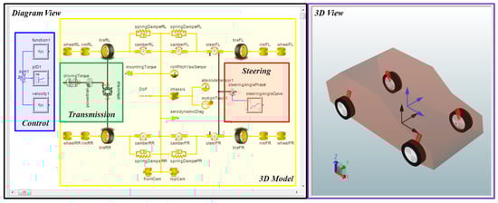
Figure 6.
The interface and vehicle dynamic model for the open differential (OD) in SimulationX.
Figure 7 shows the traction, normal force, tire speed of rear tires, and the vehicle trajectory for SA and OD cases while a 5-degree constant steering angle to the left is applied to the front wheels at 0.2 s (time = 0.2 s). Both SA and OD models show the normal forces are shifted from the inside (rear left, RL) tire to the outside (rear right, RR) tire due to the centrifugal force while cornering (Figure 7a). The traction of the inside tire is always larger than the outside tire; this causes the difficulty while turning for the SA model, whereas the differential function is achieved such that both rear tires always share the similar traction forces for the OD model (Figure 7b). As a result, the vehicle with an OD will slow down the inside tire and accelerate the outside tire, making a turn easier than the one with an SA (Figure 7c), and it has a smaller turning radius for better cornering ability (Figure 7d).
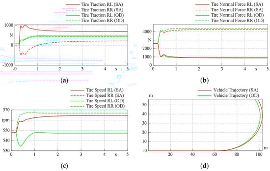
Figure 7.
The influence to vehicle turning of the solid axle (SA) and OD models, (a) tire traction; (b) tire normal force; (c) tire speed; (d) vehicle trajectory.
Next, one of the current TVD designs (SPC-TVD) was selected to understand what the torque vectoring effect is and how this effect influences the vehicle while turning. A vehicle dynamic model of the SPC-TVD shown in Figure 8 was transferred from the system configuration of the SPC-TVD shown in Figure 2a, and the only difference compared to the OD model was the transmission as shown in the diagram view. Except for the open differential, two clutches and two pairs of gearsets were added in the SPC-TVD for torque distributions.
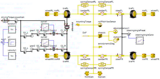
Figure 8.
The vehicle dynamic model for the SPC-TVD in SimulationX.
In this simulation, the scenario was similar to the SA and OD models. However, in order to examine the torque vectoring effect, the steering angle was fixed to zero all the time, and three cases were simulated: (a) no actuation (NA) in the SPC-TVD will happen, (b) the clutch C1 will start to be engaged at 0.2 s, and (c) the clutch C2 will start to be engaged at 0.2 s, where the speed of the vehicle is still maintained at 60 km/h over the whole process, and the simulation results including the traction of tires and the trajectory of the vehicle are recorded and illustrated in Figure 9. As shown in the simulated results, there was no turning maneuver observed when no clutch was engaged (Figure 9a). In the case of C1 engaged (Figure 9b), the traction of the inside (rear left) tire was transferred to the outside (rear right) tire, causing a torque moment to the vehicle body, and the vehicle began to turn left. Conversely, in the case of C2 engaged (Figure 9c), a similar phenomenon occurred but in the opposite direction, and the vehicle began to turn right. According to this simulation, the torque vectoring effect of the SPC-TVD was demonstrated, and the effect of the C1 and C2 engagement was shown to be opposite to the vehicle behavior (Figure 9d). Therefore, this effect could also be observed for the vehicle during cornering, while a 5-degree constant steering angle to the left was applied to the front wheels, where the curves of NA, C1, and C2 engaged cases shown in Figure 9e were denoted as neutral-steering (NS), over-steering (OS), and under-steering (US).
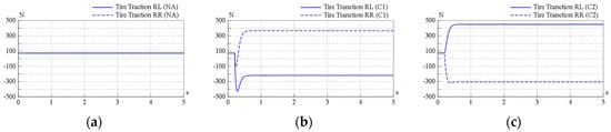
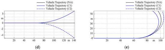
Figure 9.
Torque vectoring effect and influence of the vehicle turning of the SPC-TVD model, (a) no engagement; (b) C1 is engaged; (c) C2 is engaged; (d) without steering; (e) with a 5-degree constant steering angle.
In Figure 10, the Rav-TVD model was also transferred from the system configuration, as shown in Figure 3a, where the transmission was a differential plus one pair of the Ravigneaux gearset with two brakes (B1 and B2). The scenario was the same as in the SPC-TVD simulation, under the same vehicle speed (60 km/h) without steering for the whole process, and the three cases were: (a) no brake in the Rav-TVD will be engaged, (b) the brake B1 will start to be engaged at 0.2 s, and (c) the brake B2 will start to be engaged at 0.2 s. Figure 11 shows the simulated results for the Rav-TVD model that also had the ability to adjust the torque distributions during cornering. Therefore, the vehicle during a NS condition could be shifted to a US or OS condition by generating a torque vectoring effect to conquer or facilitate the steering maneuver. Finally, four vehicle dynamic models (SA, OD, SPC-TVD, and Rav-TVD) were put together for comparison of cornering ability, as shown in Figure 12. All of the vehicles could be observed clearly from the top view of the 3D illustration, and the trajectories showed that the SPC-TVD with the smallest turning radius had the best performance. Although the cornering ability of Rav-TVD was not as good as the SPC-TVD, however, it was still better than the SA and OD.
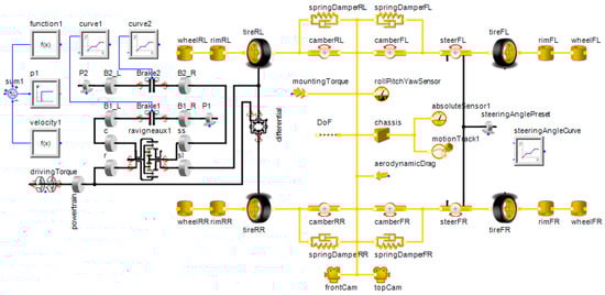
Figure 10.
The vehicle dynamic model for the Rav-TVD in SimulationX.
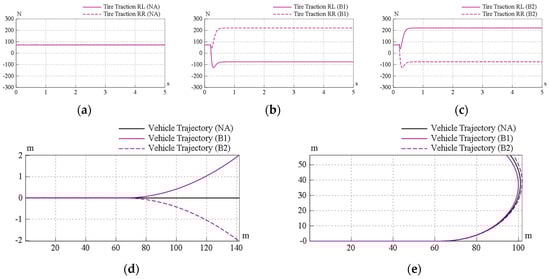
Figure 11.
Torque vectoring effect and influence of vehicle turning of the Rav-TVD model, (a) no engagement; (b) B1 is engaged; (c) B2 is engaged; (d) without steering; (e) with a 5-degree constant steering angle.
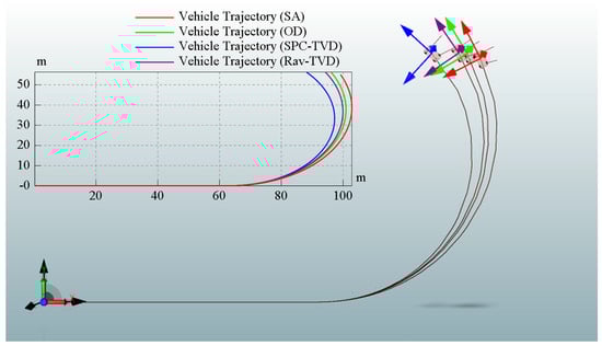
Figure 12.
Comparison of cornering for the SA, OD, SPC-TVD, and Rav-TVD models.
6. Analysis of the Numerical Simulation
In order to verify the soundness of the simulation model and understand the vehicle performance, numerical simulation with different design parameters were demonstrated. The Rav-TVD model with the original design parameters (Table A1) was selected as a benchmark, and then the simulation results with different design parameter values (gear ratios of the Ravigneaux gearset, Max. press-on force of the brakes, vehicle speed, and steering angle) were adjusted to compare. First, for the gear ratios of the Ravigneaux gearset, the values of isl and iss were changed with a variation (±10%) from the benchmark value 1.5 and 2.0. With the same scenario in previous section (for the case of steering angle = 0 degree), the simulated results are shown in Figure 13. Also, for the Max. press-on force of the brakes B1 and B2, the values were changed with a variation (±10%) from the benchmark value 7200 N, and the simulated results are shown in Figure 14. The results at t = 5 s among these parameters are collected and listed in Table 3, and iss had the largest increment and decrement on the y-direction displacement of the vehicle trajectory. As a result, adjusting the gear ratio of ring gear and small sun gear was the most efficient way to change the torque vectoring effect.
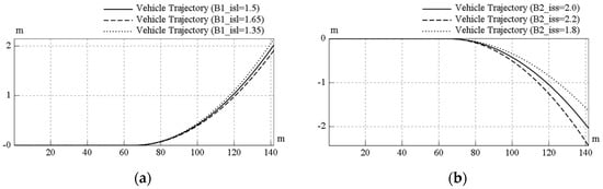
Figure 13.
Sensitivity analysis of the Rav-TVD model for different gear ratios: (a) isl and (b) iss.
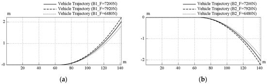
Figure 14.
Sensitivity analysis of the Rav-TVD model for different Max. press-on forces: (a) brake B1 and (b) brake B2.
Table 3.
Sensitivity analysis for the Rav-TVD model.
In Figure 15, the original vehicle speed (60 km/h) of the Rav-TVD model was changed to 30 km/h and 75 km/h. The simulation time was also extended to 475 s to make sure that the vehicle trajectory was a circular shape after one of the brakes was engaged at t = 0.2 s. This means the Rav-TVD provided the same torque vectoring effect on vehicle to make a turn. The simulated results showed that the radius of curvature of the vehicle trajectory differed from vehicle speed; the higher vehicle speed, the larger the radius of curvature. On the other hand, the parameter of constant steering angle also varied, and the original steering angle (5 degree) is already shown in Figure 11e. Under the same vehicle speed (60 km/h), different steering angles such as 1 degree and 3 degrees were also simulated, and shown in Figure 16a,b. Finally, Table 4 shows the calculated radius of curvatures from the vehicle trajectories for different conditions. In addition, a higher vehicle speed (90 km/h) and a larger steering angle (7 degree) have also been simulated; however, the vehicles flipped and turned over during torque vectoring due to the larger centrifugal force while cornering. Nevertheless, the vehicle dynamics model still had good stability, agility, and safety for most situations.
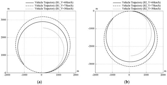
Figure 15.
Vehicle dynamics of the Rav-TVD model for different vehicle speeds while (a) B1 is engaged and (b) B2 is engaged.
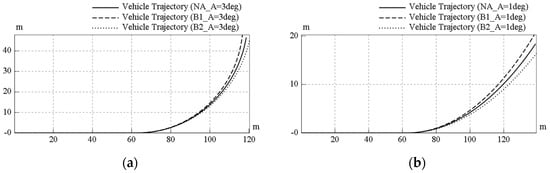
Figure 16.
Vehicle dynamics of the Rav-TVD model for different steering angle: (a) 3 degrees and (b) 1 degree.
Table 4.
Vehicle dynamics of the Rav-TVD model for different conditions.
In this section, four design parameters were selected for a sensitivity analysis and for vehicle dynamics. From the viewpoint of the mechanical dimensions of the Ravigneaux gearset, the gear ratios (isl and iss) directly affected the characteristics of the torque vectoring effect. For example, after selecting the size of the ring gear, a gearset combined by a larger large sun gear (smaller isl) and a smaller small sun gear (larger iss) had more torque vectoring power. From the viewpoint of press-on force of the brakes, the force is proportional to the torque applied on brake. Therefore, the larger press-on force, the larger the torque that is transmitted to the other side to make a turn. From the viewpoint of the vehicle trajectory, the radius of curvature is changed from various vehicle speeds and steering angles; the higher the speed or the smaller the steering angle, the lager the radius of curvature of the vehicle trajectory. Moreover, the vehicle dynamics of this model showed vehicle stability, agility, and safety at speeds under 75 km/h, and at steering angles below 5 degrees.
7. Conclusions
The development of a new vehicle component design and torque vectoring differential is demonstrated in this paper. First, the design principles of current TVDs are clarified, and their system configurations transferred from schematic diagrams are illustrated. Second, the new TVD design, which consists of a Ravigneaux gearset and two brakes, is introduced, and the feasible configuration of the Rav-TVD is discussed. Next, the interface of SimulationX software is introduced, and examples of the solid axle and open differential have been demonstrated. Due to the convenience of the system configuration, SimulationX-based models for the same vehicle equipped with different transmissions (SA, OD, SPC-TVD, and Rav-TVD) are established intuitively and directly. Simulations have been performed to show the operation of the system and the torque vectoring effects of the SPC-TVD and Rav-TVD have been demonstrated. According to the simulation results, both the SPC-TVD and Rav-TVD are able to obtain different traction distributions when different clutches or brakes are engaged, and can be used for DYC for vehicle applications. Furthermore, the cornering ability of four transmissions are simulated and compared, and numerical simulations for the Rav-TVD model have been analyzed.
In summary, our mechanical design, the Rav-TVD, has the potential for torque vectoring ability. The vehicle dynamics can also be improved with the system to fulfil driving requirements such as stability and agility, and better driving safety and performance are considered to be realizable with the new Rav-TVD design for vehicle applications.
Acknowledgments
This study is sponsored by Industrial Technology Research Institute (ITRI) of Taiwan under the Project No. F301ARY310. The technical support from Giant Lion Know-How Co., Ltd. is highly appreciated.
Author Contributions
I-Ming Chen conceived and designed the Rav-TVD system. I-Ming Chen and Yu-Fan Chen ran the simulation, and wrote the paper. Joshua Chang assisted the research. Tyng Liu is the supervisor of I-Ming Chen, Yu-Fan Chen, and Joshua Chang; he is the principal investigator who directed this research. All authors reviewed the manuscript.
Conflicts of Interest
The authors declare no conflict of interest.
Nomenclature
| DYC | direct yaw-moment control |
| ESP | electronic stability program |
| 4WS | four-wheel steering |
| TVD | torque vectoring differentials |
| DG | differential gearset |
| SPC-TVD | superposition clutch TVD |
| STC-TVD | stationary clutch TVD |
| Rav-TVD | Ravigneaux TVD |
| FPG | function power graph |
| DoF | degree-of-freedom |
| SA | solid axle |
| OD | open differential |
| P controller | Proportional controller |
| NA | no actuation |
| CAE | computer-aided engineering |
| CAD | computer aided design |
| 3D | three-dimensional |
| RL | rear left |
| RR | rear right |
| NS | neutral-steering |
| OS | over-steering |
| US | under-steering |
| Subscripts | |
| W1, W2 | left and right wheels |
| C1, C2 | clutches |
| B1, B2 | brakes |
| G, G0, G1, G2 | gear pairs |
| PG1, PG2 | planetary gearsets |
| IN | input of the engine power |
| r | ring gear |
| c | carrier |
| ss | small sun gear |
| sl | large sun gear |
Appendix A
Table A1.
Parameter value settings in the SimulationX model.
Table A1.
Parameter value settings in the SimulationX model.
| Parameters | Value |
|---|---|
| 1. Dimensions of the original Rav-TVD | |
| Radii of ring gear Rr | 60 mm |
| Radii of large sun gear Rsl | 40 mm |
| Radii of small sun gear Rss | 30 mm |
| 2. Dimensions of the original vehicle | |
| Mass | 1200 kg |
| Wheel radius (unloaded) | 310 mm |
| Tire width | 210 mm |
| Wheel base | 2.6 m |
| Truck width | 1.8 m |
| Inertia of the wheel | 0.3381 kg·m2 |
| Inertia of the powertrain | 1 kg·m2 |
| Rolling resistance coefficient of the tire | 0.01 |
| Aerodynamic drag coefficient Cd | 0.3 |
| Air density ρ | 1.204 kg/m³ |
| Frontal area of the vehicle A | 1.5 m² |
| 3. Setting of the original system parameters | |
| Gear ratio of ring gear and large sun gear isl (Rr/Rsl) | 1.5 |
| Gear ratio of ring gear and small sun gear iss (Rr/Rss) | 2.0 |
| Max. press-on force of the brakes B1 & B2 (Corresponding braking torque) | 7200 N (230 N·m) |
| Vehicle speed | 60 km/h |
| Steering angle (starts at t = 0.2 s) | 5 degree |
References
- Shibahata, Y.; Shimada, K.; Tomari, T. Improvement of vehicle maneuverability by direct yaw moment control. Veh. Syst. Dyn. 1993, 22, 465–481. [Google Scholar] [CrossRef]
- Geng, C.; Mostefai, L.; Denaï, M.; Hori, Y. Direct yaw-moment control of an in-wheel-motored electric vehicle based on body slip angle fuzzy observer. IEEE Trans. Ind. Electron. 2009, 56, 1411–1419. [Google Scholar] [CrossRef] [Green Version]
- Yim, S.; Park, Y.; Yi, K. Design of active suspension and electronic stability program for rollover prevention. Int. J. Automot. Technol. 2010, 11, 147–153. [Google Scholar] [CrossRef]
- Furukawa, Y.; Yuhara, N.; Sano, S.; Takeda, H.; Matsushita, Y. A review of four-wheel steering studies from the viewpoint of vehicle dynamics and control. Veh. Syst. Dyn. 1989, 18, 151–186. [Google Scholar] [CrossRef]
- Shibahata, Y. Torque Distributing Mechanism in Differential. U.S. Patent No. 5387161, 7 February 1995. [Google Scholar]
- Richardson, J.A. Speed Reduction Gearset and Torque Split Differential Mechanism. U.S. Patent No. 5,643,129, 1 January 1997. [Google Scholar]
- Gumpoltsberger, G.; Baasch, D. Transmission for Distributing a Drive Torque. U.S. Patent No. 7,056,252, 6 June 2006. [Google Scholar]
- Gradu, M. Differential with Torque Vectoring Capabilities. U.S. Patent No. 7,238,140, 3 July 2007. [Google Scholar]
- Platt, W. Continuously Variable Torque Vectoring Axle Assembly. U.S. Patent No. 7,951,035, 31 May 2011. [Google Scholar]
- Wheals, J.C.; Baker, H.; Ramsey, K.; Turner, W. Torque vectoring AWD driveline: Design, simulation, capabilities and control (No. 2004-01-0863). SAE Tech. Pap. 2004. [Google Scholar] [CrossRef]
- Kakalis, L.; Cheli, F.; Sabbioni, E. The Development of a Brake based Torque Vectoring System for a Sport Vehicle Performance Improvement. In Proceedings of the 6th International Conference on Informatics in Control, Automation and Robotics, Intelligent Control Systems and Optimization, Milan, Italy, 2–5 July 2009; pp. 298–304. [Google Scholar]
- Lin, C.; Xu, Z. Wheel torque distribution of four-wheel-drive electric vehicles based on multi-objective optimization. Energies 2015, 8, 3815–3831. [Google Scholar] [CrossRef]
- De Pinto, S.; Camocardi, P.; Sorniotti, A.; Gruber, P.; Perlo, P.; Viotto, F. Torque-Fill Control and Energy Management for a Four-Wheel-Drive Electric Vehicle Layout With Two-Speed Transmissions. IEEE Trans. Ind. Appl. 2017, 53, 447–458. [Google Scholar] [CrossRef]
- De Novellis, L.; Sorniotti, A.; Gruber, P.; Shead, L.; Ivanov, V.; Hoepping, K. Torque vectoring for electric vehicles with individually controlled motors: State-of-the-art and future developments. In Proceedings of the 26th Electric Vehicle Symposium, Los Angeles, CA, USA, 6–9 May 2012. [Google Scholar]
- Deur, J.; Ivanović, V.; Hancock, M.; Assadian, F. Modeling and analysis of active differential dynamics. J. Dyn. Syst. Meas. Control 2010, 132, 061501. [Google Scholar] [CrossRef]
- Chen, I.M.; Yang, T.H.; Liu, T. Function Power Graph A Novel Methodology for Powertrain and Hybrid System Conceptual Design and Analysis. In Proceedings of the 14th IFToMM World Congress, Taipei, Taiwan, 25–30 October 2015; pp. 544–552. [Google Scholar]
- Wang, C.; Zhao, Z.; Zhang, T.; Dai, X.; Yuan, X. Development of a compact compound power-split hybrid transmission based on altered Ravigneaux gear set. SAE Tech. Pap. 2014. [Google Scholar] [CrossRef]
- Zhang, Y.; Ma, X.; Yin, C.; Yuan, S. Development and Simulation of a Type of Four-Shaft ECVT for a Hybrid Electric Vehicle. Energies 2016, 9, 141. [Google Scholar] [CrossRef]
- Zhao, L.; Zhou, Y.; Zheng, L. Modeling and simulation of AMT clutch actuator based on simulationX. In Proceedings of the CiSE 2009. International Conference on Computational Intelligence and Software Engineering, Wuhan, China, 11–13 December 2009; pp. 1–5. [Google Scholar]
- Chen, L.; Xi, G.; Yin, C.L. Model referenced adaptive control to compensate slip-stick transition during clutch engagement. Int. J. Automot. Technol. 2011, 12, 913–920. [Google Scholar] [CrossRef]
- Guo, W.; Wang, S.H.; Su, C.G.; Li, W.Y.; Xu, X.Y.; Cui, L.Y. Method for precise controlling of the at shift control system. Int. J. Automot. Technol. 2014, 15, 683–698. [Google Scholar] [CrossRef]
- Farkas, Z.; Jóri, I.J.; Kerényi, G. The Application and Modelling Possibilities of CVT in Tractor. In Proceedings of the 5th International Conference Multidisciplinary, Baia Mare, Romania, 23–24 May 2003; pp. 145–150. [Google Scholar]
- Ji, J.; Jang, M.J.; Kwon, O.E.; Chai, M.J.; Kim, H.S. Power transmission dynamics in micro and macro slip regions for a metal v-belt continuously variable transmission under external vibrations. Int. J. Automot. Technol. 2014, 15, 1119–1128. [Google Scholar] [CrossRef]
- Kim, D.M.; Kim, S.C.; Noh, D.K.; Jang, J.S. Jerk phenomenon of the hydrostatic transmission through the experiment and analysis. Int. J. Automot. Technol. 2015, 16, 783–790. [Google Scholar] [CrossRef]
- Tang, P.; Wang, S.; Liu, Y.; Xu, X. Analysis of the oil pressure rule during the shift process of automatic transmission. In Proceedings of the 2010 Seventh International Conference on Fuzzy Systems and Knowledge Discovery (FSKD), Yantai, China, 10–12 August 2010; Volume 1, pp. 109–113. [Google Scholar]
- Pengxiang, T.; Shuhan, W.; Xiangyang, X.; Wenyong, L.; Lin, S.; Guoru, Z. Notice of Retraction Design of system pressure valve of 8-speed automatic transmission. In Proceedings of the 2010 International Conference on Computer Application and System Modeling (ICCASM), Taiyuan, China, 22–24 October 2010; Volume 4. [Google Scholar]
- Wang, S.H.; Xu, X.Y.; Liu, Y.F.; Dai, Z.K.; Tenberge, P.; Qu, W. Design and dynamic simulation of hydraulic system of a new automatic transmission. J. Cent. South Univ. Technol. 2009, 16, 697–701. [Google Scholar] [CrossRef]
- Wei, G.; Xiangyang, X.; Yongxin, C.; Yang, Y. Simulation of powertrain and dynamics of automobile based on SimulationX. In Proceedings of the 2011 6th IEEE Conference on Industrial Electronics and Applications (ICIEA), Beijing, China, 21–23 June 2011; pp. 2326–2330. [Google Scholar]
- Dai, Z.; Liu, Y.; Xu, X.; Wang, S. The Application of Multi-domain Physical System Simulation Method in the Study of Automatic Transmissions. In Proceedings of the WCSE’09. WRI World Congress on Software Engineering, Xiamen, China, 19–21 May 2009; Volume 2, pp. 504–508. [Google Scholar]
- Belmon, L.; Yan, J.; Abel, A. Modelling and Simulation of DCT Gearshifting for Real-Time and High-Fidelity Analysis. In Proceedings of the FISITA 2012 World Automotive Congress, Beijing, China, 27–30 November 2013; pp. 399–411. [Google Scholar]
- Li, W.; Abel, A.; Todtermuschke, K.; Zhang, T. Hybrid vehicle power transmission modeling and simulation with simulationX. In Proceedings of the ICMA 2007, International Conference on Mechatronics and Automation, Harbin, China, 5–8 August 2007; pp. 1710–1717. [Google Scholar]
- Ma, X.; Zhang, Y.; Yin, C. Kinematic Study and Mode Analysis of a New 2-Mode Hybrid Transmission. In Proceedings of the FISITA 2012 World Automotive Congress, Beijing, China, 27–30 November 2013; pp. 309–318. [Google Scholar]
- Abel, A.; Adir, A.; Blochwitz, T.; Greenberg, L.; Salman, T. Development and verification of complex hybrid systems using synthesizable monitors. In Proceedings of the Haifa Verification Conference, Haifa, Israel, 5–7 November 2013; pp. 182–198. [Google Scholar]
- Bös, M. Subsystem- and full-vehicle-simulation of mobile machines using Simulation X. In Proceedings of the 15th ITI Symposium, Dresden, Germany, 14–15 November 2012. [Google Scholar]
- Tüschen, T. SIMULATORS–‘auto. mobile-driving simulator’–suspensions design of a wheel-based driving simulator. In Proceedings of the 7th International Munich Chassis Symposium 2016, Munich, Germany, 14–15 June 2016; Springer Fachmedien Wiesbaden: Wiesbaden, Germany, 2017; pp. 411–434. [Google Scholar]
© 2017 by the authors. Licensee MDPI, Basel, Switzerland. This article is an open access article distributed under the terms and conditions of the Creative Commons Attribution (CC BY) license (http://creativecommons.org/licenses/by/4.0/).