Article

Unified Brake Service by a Hierarchical Controller for Active Deceleration Control in an Electric and Automated Vehicle

1
State Key Laboratory of Automotive Safety and Energy, Tsinghua University, Beijing 100084, China
2
China national institute of standardization, Beijing 100191, China
*
Author to whom correspondence should be addressed.
Energies 2017, 10(12), 2052; https://doi.org/10.3390/en10122052
Submission received: 2 November 2017 / Revised: 20 November 2017 / Accepted: 20 November 2017 / Published: 4 December 2017
(This article belongs to the Special Issue The International Symposium on Electric Vehicles (ISEV2017))

Abstract

:
Unified brake service is a universal service for generating certain brake force to meet the demand deceleration and is essential for an automated driving system. However, it is rather difficult to control the pressure in the wheel cylinders to reach the target deceleration of the automated vehicle, which is the key issue of the active deceleration control system (ADC). This paper proposes a hierarchical control method to actively control vehicle deceleration with active-brake actuators. In the upper hierarchical, the target pressure of wheel cylinders is obtained by dynamic equations of a pure electric vehicle. In the lower hierarchical, the solenoid valve instructions and the pump speed of hydraulic control unit (HCU) are determined to satisfy the desired pressure with the feedback of measured wheel cylinder pressure by pressure sensors. Results of road experiments of a pure electric and automated vehicle indicate that the proposed method realizes the target deceleration accurately and efficiently.

1. Introduction

Automated driving is a big trend on the evolutions of traditional internal combustion vehicles [1,2]. On such an automated vehicle, body motions, such as acceleration, deceleration and steering, are controlled by machines, not the driver. Unified brake service (UBS) aims to realize the target deceleration requested from the intelligent or automated driving systems [3,4,5,6,7] and becomes a base of many Advance Driver Assist Systems (ADAS) such as Lane Keeping Assist (LKA), Adaptive Cruiser Control (ACC), Automatic Emergency Brake (AEB) and Active Deceleration Control (ADC) [8,9,10,11]. Generally, many of these intelligent systems have the demand of putting the brakes on the wheels, which may result in conflicting objects of target wheel pressures and the repetitive design of the wheel pressures controller. A promising solution is to build the unified brake service for providing the universal wheel brake of the vehicle. In this paper, it is our goal to provide such a unified brake service for active deceleration control of an electric and automated sport utility vehicle.
The key issue of building the unified brake service is to provide the accurate pressure of the wheel cylinders [12,13,14]. However, it is no easy work to get the real-time information of all of the wheel pressure. There are several studies dedicated to this topic and researchers have made some progress in this area [15,16,17]. However, pressure estimation is very difficult and sometimes not suitable for pressure control due to estimation error. An alternative way is to measure the wheel pressure straightforwardly with pressure sensors [18,19,20]. The costs of the pressure sensors are affordable when it comes to an automated driving system [21,22].
Many actuators have been developed to control the wheel pressures. A traditional electro-hydraulic brake (EHB) can be applied for vehicle dynamic control including deceleration [23,24]. A magnetorheological and wedge mechanism-based brake-by-wire system is proposed to harvest brake energy [25]. Other actuators such as an electro-mechanical brake (EMB) and in-wheel motor are the potential technics to provided a unified brake service [26,27,28,29].
In this paper, a hierarchical control method is proposed to control vehicle deceleration in an active and timely manner. In the upper hierarchical control, the target pressure of wheel cylinders is obtained to satisfy the desired deceleration. In detail, the target pressure consists of two parts, namely, the base pressure and the compensation pressure. The base pressure is derived from dynamic equations of a pure electric vehicle as the feedforward control loop. The compensation pressure is calculated by a Proportion-Integration-Differentiation (PID) controller with the feedback of the value of real deceleration measured by the longitudinal acceleration sensor. In the lower hierarchical control, the target duty cycle of solenoid valve in Pulse-Width Modulation (PWM) control mode and the target pump speed of hydraulic control unit are obtained to meet the demanded pressure. Similarly, these target values consist of two parts: the base values and the compensation values. The base values are calibrated by massive onboard vehicle tests. The compensation values are calculated by a feedback controller with the real-time values of wheel cylinder pressure from pressure sensors.
The rest of the paper is organized as follows. Section 2 introduces the whole control architecture of ADC in general and the upper hierarchical controller in detail. Section 3 describes how to design the upper hierarchical controller with verifications of onboard vehicle tests. Results and analysis of on-road experiments are given in Section 4. At last, the conclusions are presented in Section 5.

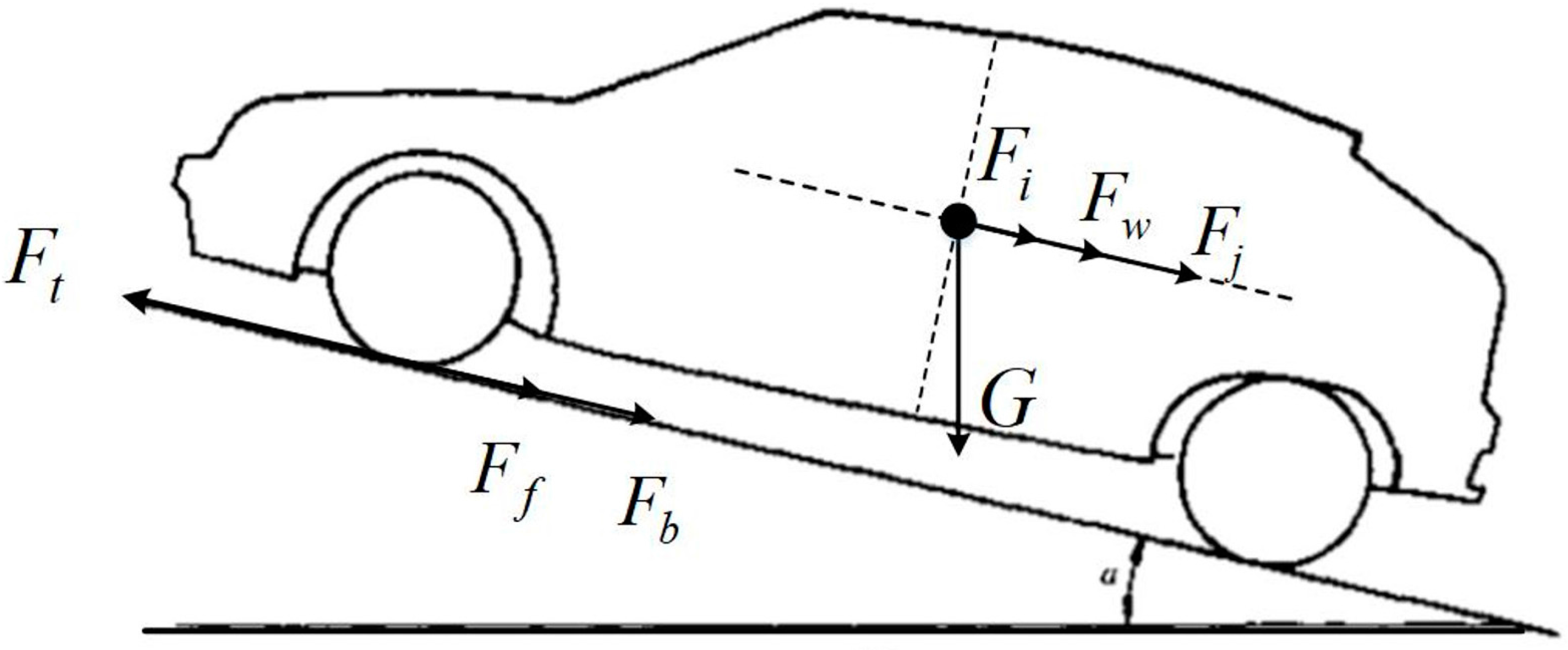
2. Dynamic Model of Electric Vehicle

Longitudinal motion of a pure electric vehicle is shown in Figure 1. In addition, the equilibrium equation is as follows:
F t = F f + F w + F i + F j + F b ,
where F t is the motor drive force, F f is the tire resistant force, F w is the air drag force, F i is the slope resistant force, F j is the acceleration force, and F b is the active brake force.
Expanding Equation (1), we get:
T tq i g i 0 η T r = G f + C D A 21.15 u 2 + G i + δ m d u d t + K P b a s e ,
where T tq is the motor torque, i g is the transmission ratio of gear box, i 0 is the final ratio, η T is the coefficient of powertrain efficiency, r is the effective radius of tire, G is vehicle gravity, C D is the coefficient of air drag, A is the frontal area, u is vehicle velocity, i is gradient of road, δ is the coefficient of equivalent inertia of the vehicle, m is the total mass, d u / d t is the desired longitudinal acceleration, K is the coefficient of brake torque, and P a i m is base pressure.

3. Design of the Hierarchical Controller

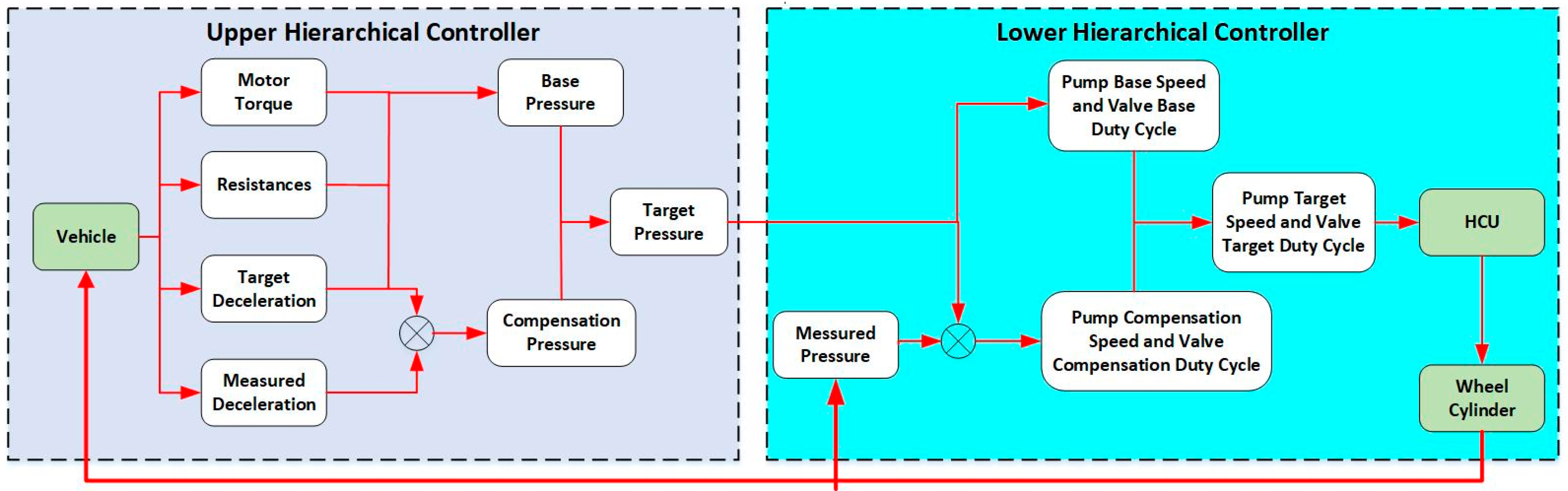
3.1. The Layout of the Whole Control Architecture

The sketch of the control architecture of ADC system is presented in Figure 2. The whole scheme can be divided into two blocks: the upper hierarchical controller blocks and the lower hierarchical controller blocks. Firstly, the active safety systems or driver assist systems call for a target deceleration to control the vehicle motion or avoid collision. Then, the upper hierarchical controller calculates the target wheel pressure to cater to the desired longitudinal deceleration of the vehicle body. The lower hierarchical controller, which is the core of the unified pressure brake services, gives appropriate instructions to the solenoid valve and the hydraulic pump to meet the demand pressure. Finally, a suitable amount of brake fluid flows into the wheel cylinders to decelerate the vehicle.

3.2. Design of Upper Hierarchical Controller

The upper hierarchical controller deduces the base pressure from the equilibrium equation of vehicle longitudinal dynamics, which is a feedforward control loop. This control method is direct but not accurate due to model nonlinearity and uncertainty. A feedback control loop is integrated to ensure the accurate and fast control of vehicle deceleration. Thus, the compensation pressure is calculated by a PID controller. In addition, the target pressure is the result of base pressure and compensation pressure.
Reshaping Equation (2), we get Equation (3):
P b a s e = 1 K [ T tq i g i 0 η T r G f C D A 21.15 u 2 G i δ m d u d t ] .
Hence, the base pressure is derived to meet with the desired deceleration and the feedforward loop is setup in this controller.
To track the target deceleration accurately and in time, a PID controller is designed utilizing information of vehicle longitudinal deceleration from the accelerometer mounted on the mass center. Taking the error between the target deceleration and the measured deceleration as control input, the PID controller is as follows:
P c o m = K p × e + K i × e d t + K d × e ˙ ,
where the control output P c o m is compensation pressure, and e is the error between the target deceleration and the measured deceleration. e d t denotes the integration of variable e . Similarly, e ˙ is the differential of variable e . The PID parameters, namely K p , K i , K d , are calibrated by onboard vehicle tests.
As is presented in Figure 1, the target wheel pressure P t a r , which is the output of the upper hierarchical controller, is the sum of base pressure and compensation pressure:
P t a r = P b a s e + P c o m .

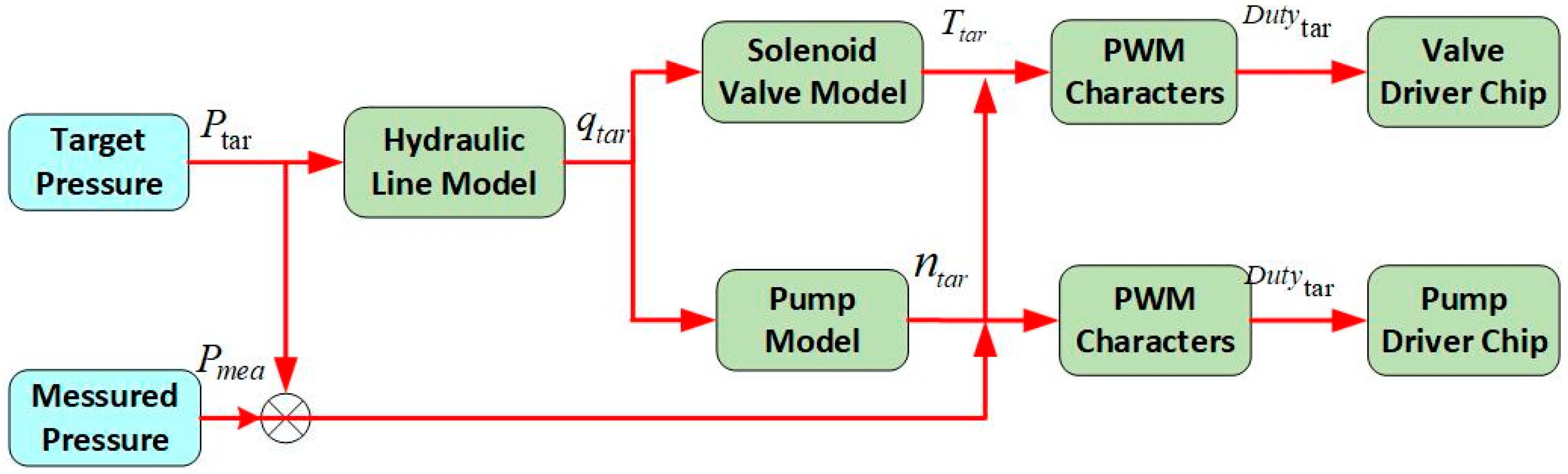
3.3. Design of Lower Hierarchical Controller

The actuator of the ADC system is similar to that of Electronics Stability Control (ESC). It is called an Electronic and Hydraulic Control Unit (EHCU), which is composed of two main parts, namely, the Electronic Control Unit (ECU) [30] and Hydraulic Control Unit (HCU) [31], as is shown in Figure 3. The proposed controller is run on the embedded chip of the ECU we designed and ECU executes the instruction of the duty of pump and solenoid valves to control HCU. Thus, the HCU regulates the hydraulic pressure of each wheel in the brake system actively. Furthermore, five pressure sensors are also adopted in the project to provide real-time information about pressure. Four sensors are mounted on each wheel of the vehicle while the left one is set on the main container of the brake system, as is depicted in Figure 4.
The lower hierarchical controller aims to realize the desired wheel pressure by adjusting the duty cycle of solenoid valve and pump speed. In the feedforward loop, the base values of valve duty and pump speed are calibrated by massive onboard vehicle tests. In the pressure increment test, only the pump works and the drive current of the valve is cut off. Thus, the valve duty is 0 and the pump duty varies from 0% to 100%. On the contrary, in the pressure decrement test, the pump is shut down and only the valve is activated. In this case, the pump duty is set to be zero and the valve duty varies from 0% to 100%. In this way, the increment rate and decrement rate of pressure are determined. The results are presented in Table 1.
Due to the complexity and nonlinearity of hydraulic system, it is not easy to track the desired pressure without error. Thus, a feedback controller is built with the real-time information of wheel cylinder pressure, and the compensation values are calculated by this controller to fix the model error. The structure of the lower hierarchical controller is shown in Figure 5.
The hydraulic model is simplified as follows:
Δ P = K × Δ t = { K i n c × Δ t ,     Δ P > 0 0 ,                    Δ P = 0 K d e c × Δ t .     Δ P < 0 ,
where Δ P is the difference between the target pressure and the measured pressure. In other words, Δ P = P t a r P m e a . Δ t is the control cycle, and it equals 10 ms in our controller. K i n c is the increment rate of pressure. K d e c is the decrement rate of pressure.
A lookup table is setup in the lower controller to find the relationship between the pressure rate and the duty cycle of valves and pump. When the pressure rate K is calculated, a suitable set of valve duty D v a l v e _ b a s e and pump duty D p u m p _ b a s e will be found to satisfy the target pressure.
To eliminate the model error, compensation duty cycle of are added as feedbacks, which are calibrated by experiments. In addition, they are ruled by Equation (7):
{ D v a l v e _ c o m = K v a l v e × Δ P D p u m p _ c o m = K p u m p × Δ P .
As is presented in Figure 4, the target duty cycle of valve and pump, which are the output of the lower hierarchical controller, are the sum of base duty and compensation duty:
{ D v a l v e _ t a r = D v a l v e _ b a s e + D v a l v e _ c o m D p u m p _ t a r = D p u m p _ b a s e + D p u m p _ c o m .

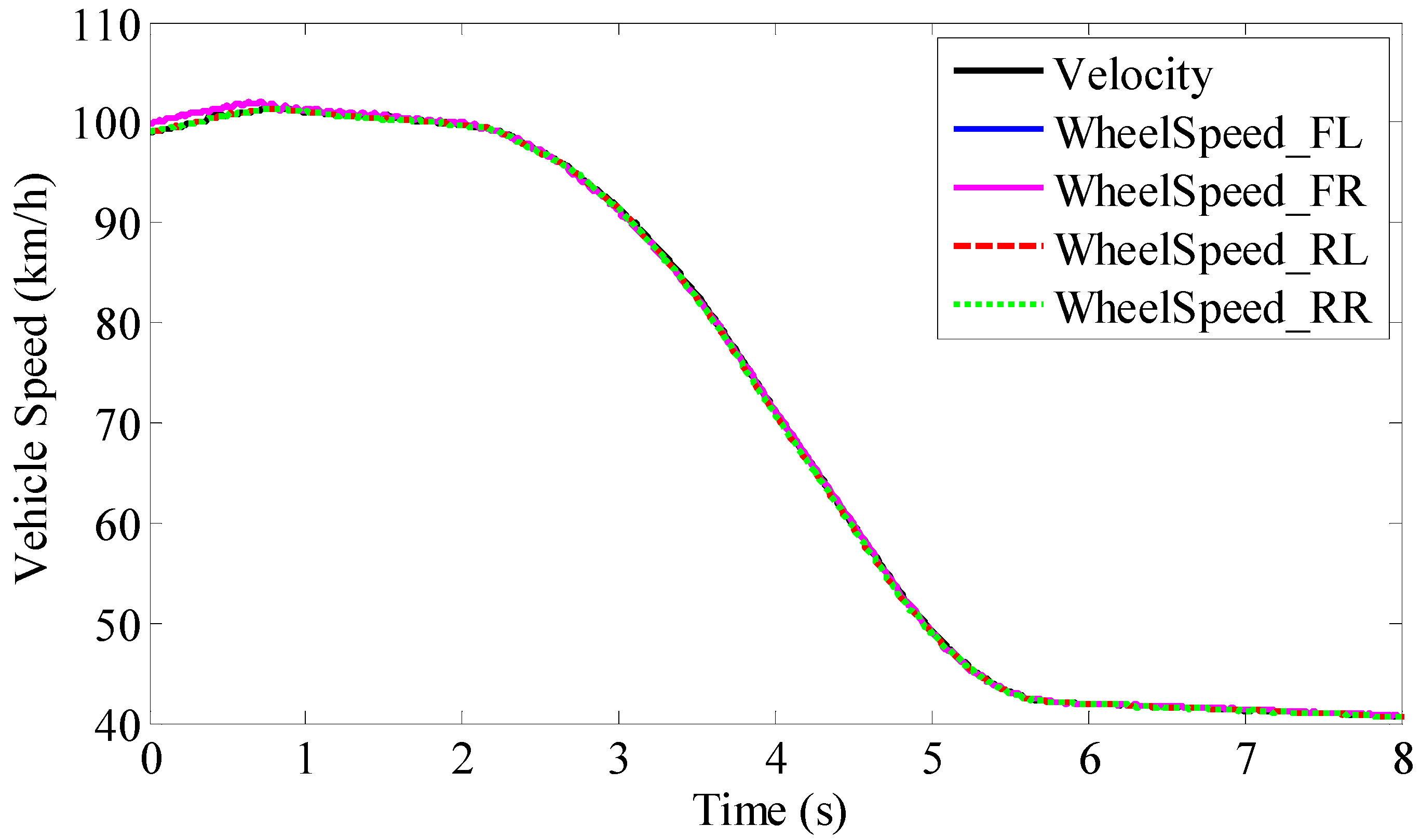
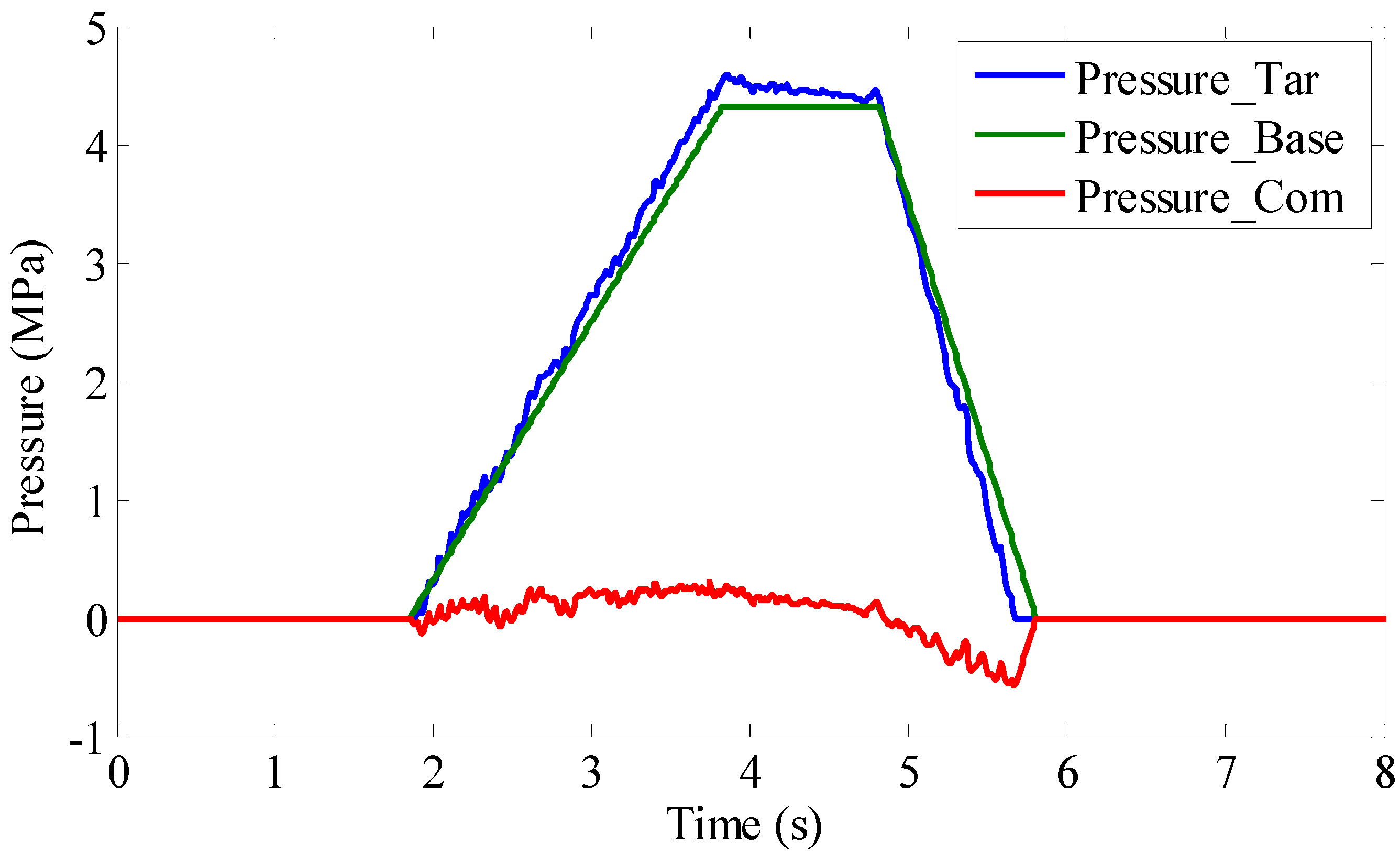
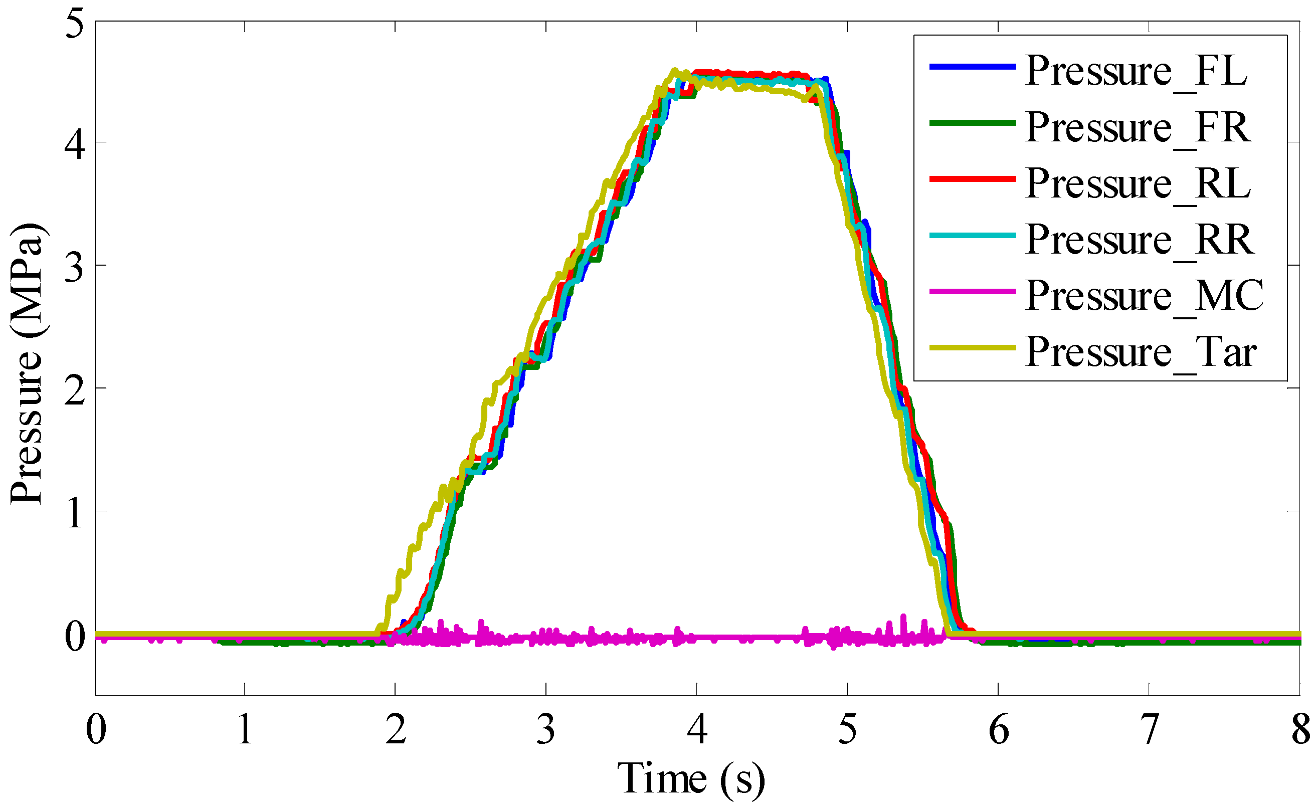
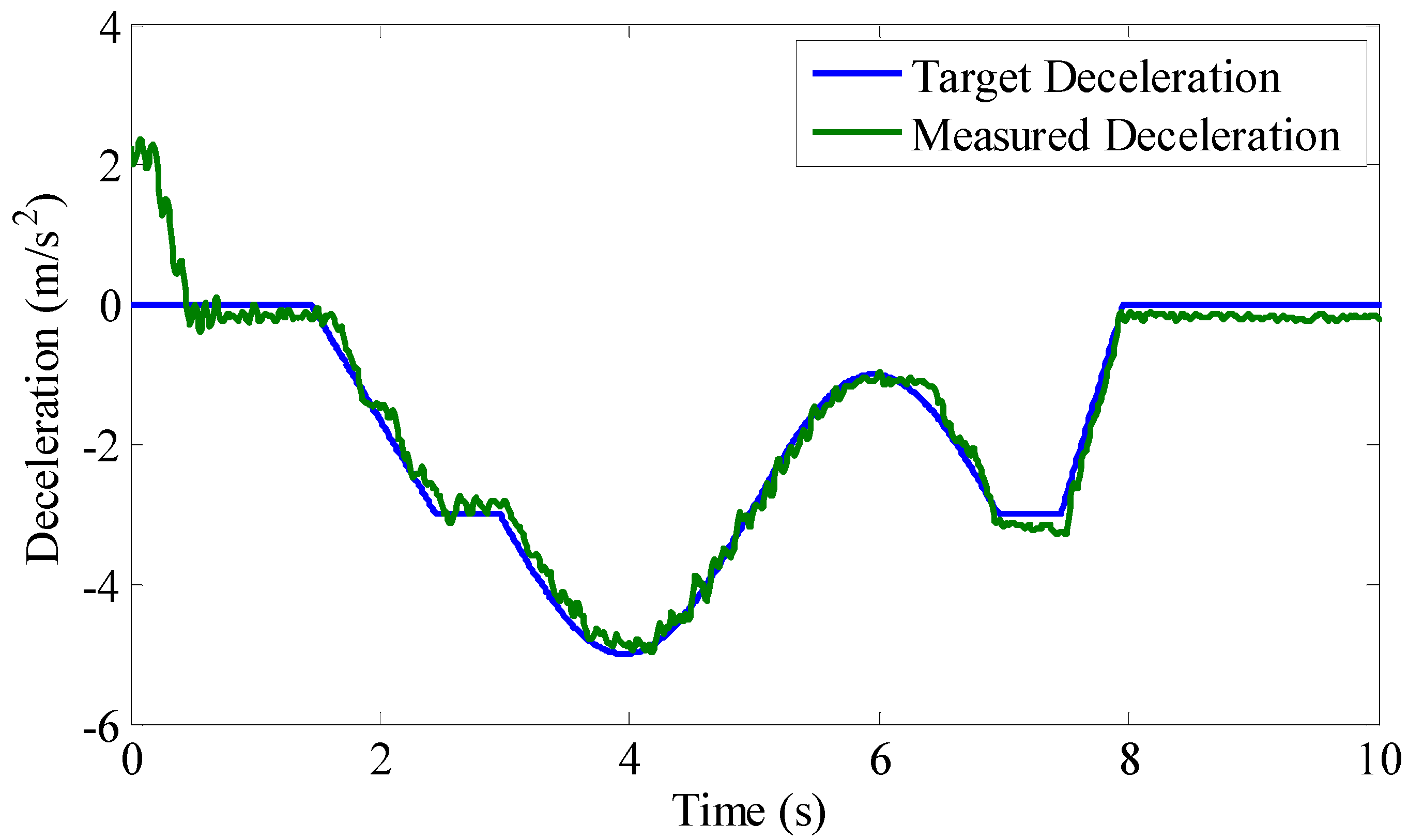
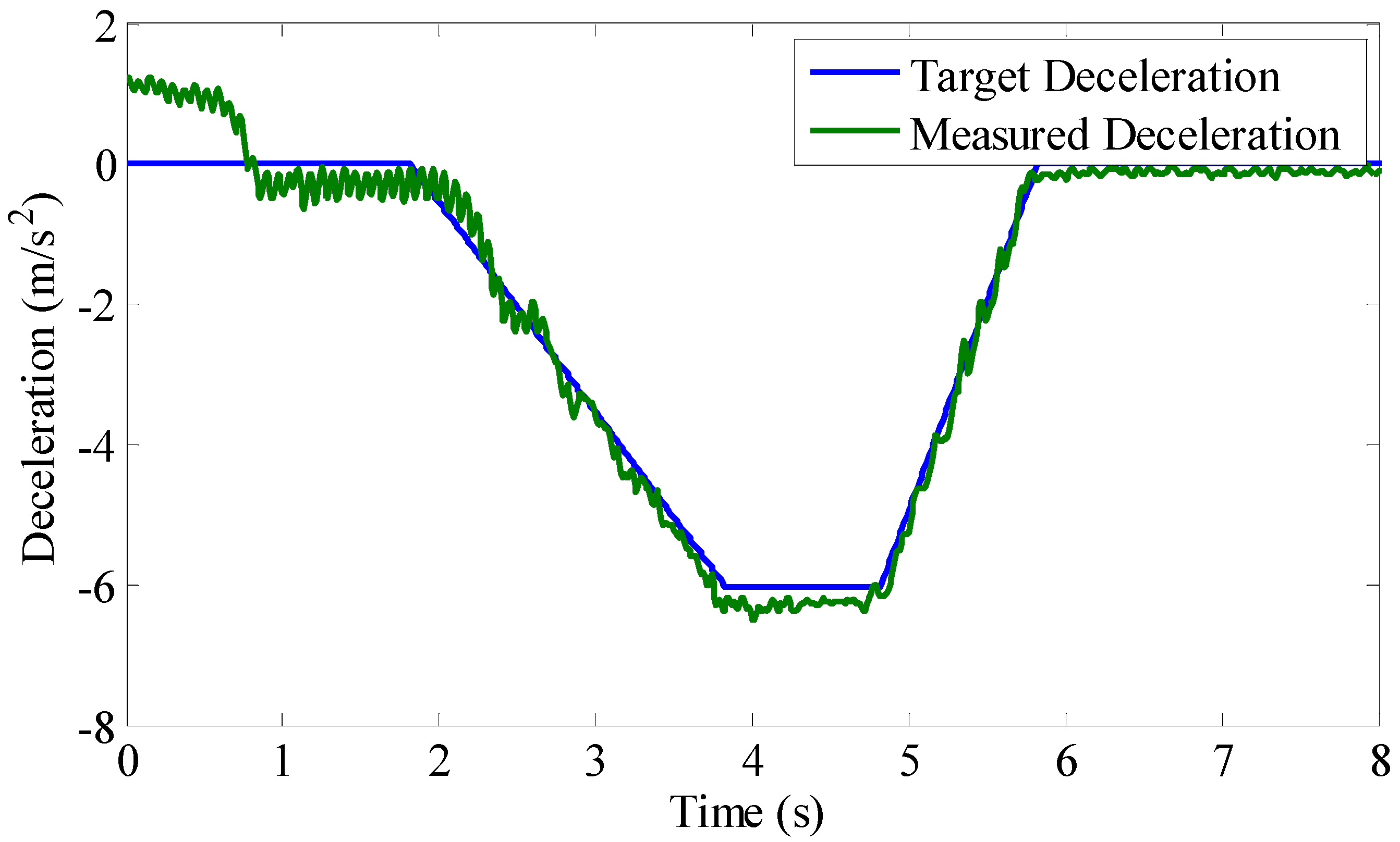
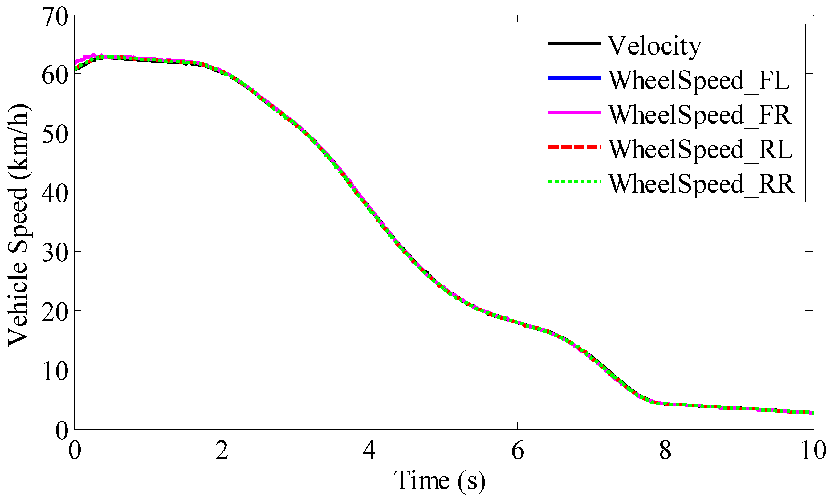
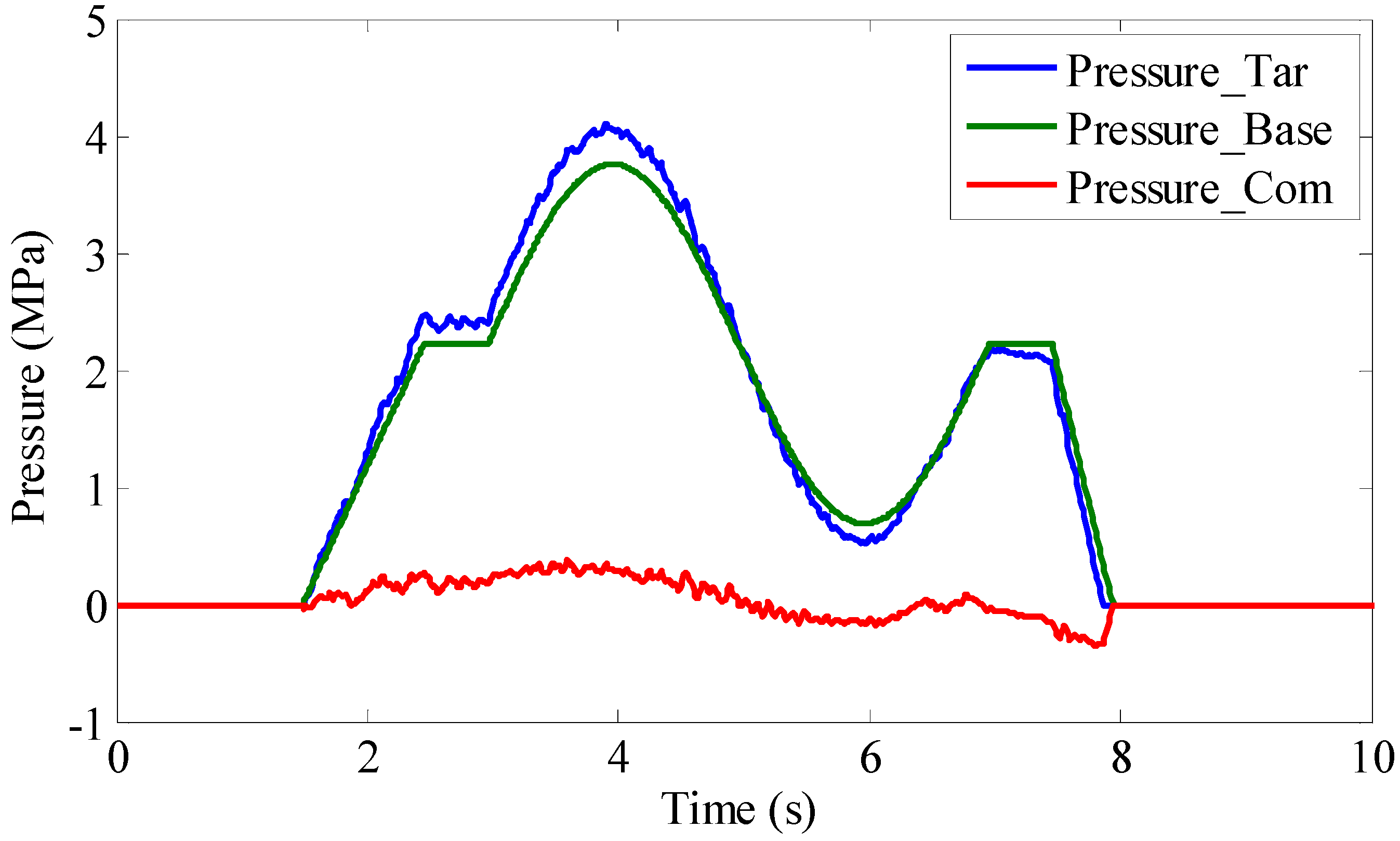
4. Results and Analysis of Vehicle Experiments

A number of on-road tests were conducted on a pure electric and automated sport utility vehicle (SUV) (see Figure 6) to verify the performance of the proposed controller. This SUV has been modified to install an electronic and hydraulic control unit (EHCU), which is the hardware platform of our active deceleration control system. From the picture, it can be seen that the EHCU is mounted on the engine comportment with the steel support. The HCU is connected to the brake system with pipes and the ECU is connected to the controller area network and on-board sensors by wires. The vehicle parameters are shown in Table 2.
Two typical scenarios are implemented on a straightforward road, namely, the ladder deceleration test and the sinusoidal deceleration test. The ladder deceleration test, as the name suggested, has a ladder-shaped desired deceleration, with a variety of initial velocity and deceleration. This test aims to simulate the typical bake behavior of most drivers in the traffic of relatively good quality. Due to space limitation, a ladder test with an initial speed of 100 km/h and max target deceleration of −5 m/s2 is chosen in this paper. Similarly, the sinusoidal deceleration test has a sinusoidal-shaped deceleration with different speeds and deceleration. This test is conducted to simulate the aggressive brake of driver in the traffic. In addition, a sinusoidal-shaped with an initial speed of 60 km/h, and the max target deceleration of −5 m/s2 is also selected as an example to analyze the performance of active deceleration control system. The test results of two tests are shown in figures below.
The example of ladder deceleration test uses data that were measured over a time span of 8 s with a sampling period of 10 ms. Figure 7 shows the speed of each wheel and the vehicle velocity during the test, which were reduced steadily and smoothly when the wheel pressure applied. Figure 8 shows the outcome of the upper controller, the target pressure of each wheel. In our on-road tests, it was found that the base pressure made a contribution of about 80% of the final target pressure on average, leaving the remaining 20% of the compensation pressure. Results of the lower controller are shown in Figure 9. The pressure of each wheel cylinder tracks the target pressure well thanks to the feedforward of the pressure model and the feedback of pressure sensors. The delay of pressure response is less than 300 ms on average, although there is a little lag at the beginning of pressure control due to the actuator gaps of the brake system. By calculating the Root-Mean-Square Deviation (RMSD) and the Normalized Root-Mean-Square Deviation (NRMSD) of the measured value versus the target value as given in Table 3, it is found that the real wheel pressure agreed with the target value precisely and in time.
The targets and results of the active deceleration control system are shown in Figure 10, which depicts the target deceleration and the measured deceleration. In the first second, the vehicle was accelerated by driver so that the entrance condition of active deceleration control was not qualified and the active deceleration control didn’t work. In the next 1 s, the sport utility vehicle was sliding with a deceleration of −0.2 m/s2 and the active brake control system didn’t intervene because the target value is zero. After 2 s, the amplitude of target deceleration increased to a maximum value of 6 m/s2 and held on for 1 s and then decreased to zero. Under the control of an active brake system, the measured deceleration of vehicle tracked the target curve well with an average time delay of less than 100 ms. By considering the root-mean-square deviation (RMSD) and the normalized root-mean-square deviation (NRMSD) as given in Table 3, it can be concluded that the real vehicle deceleration tracked the target value in an accurate and timely manner.
In the example of sinusoidal deceleration test, the active deceleration control system was triggered by the driver at around 1 s with an initial speed of 60 km/h and the target deceleration was sent on a controller area network (CAN) bus in a sinusoidal shape with a frequency of 0.25 Hz and amplitude of 2 m/s2, as is shown in Figure 11. In Figure 12, the base pressure calculated by the upper controller took a main part in the final target pressure, leaving the PID pressure to compensate the model error. In Figure 13, the system pumped suitable pressure up to 4 Mpa to the wheel cylinders swiftly and independently to meet the brake demand. In addition, the RMSD and NRMSD of this test are shown in Table 4. As a result, the real deceleration of vehicle body followed the target deceleration quite well, even at a sharp corner in the target deceleration curve (see Figure 14), showing a good quality of pressure execution during the much more random deceleration test, with the proof of the analysis data in Table 4. Compared with the ladder test, the compensation pressure in the sinusoidal test played a more important role on the outcome of the upper controller because the brake demand in the sinusoidal test is more dynamic.
In general, the proposed hierarchical controller tracked the target deceleration in an accurate and timely manner, while keeping directional stability of the vehicle. During the stage of deceleration, vehicle speed decreased smoothly while the driver felt comfortable and easy. Once the car stopped, the measured deceleration returned to a default value of zero.

5. Conclusions

In this paper, a hierarchical control method is proposed for unified brake service to meet the demand of the active deceleration control of an electric and automated sport utility vehicle. In the upper hierarchical controller, the desired pressure of wheel cylinders is calculated to satisfy the target deceleration from the vehicle, while the solenoid valve instructions and the pump speed of HCU are determined to realize the target pressure in the lower controller. The actuator of the active deceleration control system, EHCU, was installed on the brake system of the tested vehicle with an extra equipment of pressure sensors of each wheel. Results of on-road vehicle tests show good performance of the proposed method, with the proof of the analysis data of RMSD and NRMSD. The hydraulic pressure is well applied to the wheel cylinders in an accurate and timely manner due to the feedforward of pressure model and feedback of pressure sensors. Furthermore, in future work, the unified brake service will be applied widely to driver assistant systems such as AEB to check the performance of the controller in severe brake cases and improve the robustness of the active deceleration controller.

Acknowledgments

This project was supported by the National Science Fund of China (Grant No. 51375009).

Author Contributions

Yahui Liu conceived the whole control architecture of the active dceleration controller; Yuliang Nie designed the detiled upper and lower hierarchical controller; Shuo Cheng and Yuliang Nie performed the experiments; Mingming Mei analyzed the data; Lingyun Xiao contributed reagents/materials/analysis tools; Yahui Liu wrote the paper.

Conflicts of Interest

The authors declare no conflict of interest.

References

  1. McGehee, D.V.; Brewer, M.; Schwarz, C.; Smith, B.W. Review of Automated Vehicle Technology: Policy and Implementation Implications; Iowa Department of Transportation: Ames, IA, USA, 2016.
  2. Buechel, M.; Frtunikj, J.; Becker, K.; Sommer, S.; Buckl, C.; Armbruster, M.; Marek, A.; Zirkler, A.; Klein, C.; Knoll, A. An automated electric vehicle prototype showing new trends in automotive architectures. In Proceedings of the 2015 IEEE 18th International Conference on Intelligent Transportation Systems, Las Palmas, Spain, 15–18 September 2015; pp. 1274–1279. [Google Scholar]
  3. Li, L.; Lu, Y.; Wang, R.; Chen, J. A Three-Dimensional Dynamics Control Framework of Vehicle Lateral Stability and Rollover Prevention via Active Braking With MPC. IEEE Trans. Ind. Electron. 2017, 64, 3389–3401. [Google Scholar] [CrossRef]
  4. Tchamna, R.; Youn, E.; Youn, I. Combined control effects of brake and active suspension control on the global safety of a full-car nonlinear model. Veh. Syst. Dyn. 2014, 52, 69–91. [Google Scholar] [CrossRef]
  5. Chen, J.; Song, J.; Li, L.; Ran, X.; Jia, G.; Wu, K. A novel pre-control method of vehicle dynamics stability based on critical stable velocity during transient steering maneuvering. Chin. J. Mech. Eng. 2016, 29, 475–485. [Google Scholar] [CrossRef]
  6. Li, B.; Rakheja, S. Jackknifing Prevention of Tractor-Semitrailer Combination Using Active Braking Control; SAE Technical Paper; SAE International: Warrendale, PA, USA, 2015.
  7. Wu, J.; Cheng, S.; Liu, B.; Liu, C. A Human-Machine-Cooperative-Driving Controller Based on AFS and DYC for Vehicle Dynamic Stability. Energies 2017, 10, 1737. [Google Scholar] [CrossRef]
  8. Bengler, K.; Dietmayer, K.; Farber, B.; Maurer, M.; Stiller, C.; Winner, H. Three decades of driver assistance systems: Review and future perspectives. IEEE Intell. Transp. Syst. Mag. 2014, 6, 6–22. [Google Scholar] [CrossRef]
  9. McCall, J.C.; Trivedi, M.M. Video-based lane estimation and tracking for driver assistance: Survey, system, and evaluation. IEEE Trans. Intell. Transp. Syst. 2006, 7, 20–37. [Google Scholar] [CrossRef]
  10. Vahidi, A.; Eskandarian, A. Research advances in intelligent collision avoidance and adaptive cruise control. IEEE Trans. Intell. Transp. Syst. 2003, 4, 143–153. [Google Scholar] [CrossRef]
  11. Coelingh, E.; Eidehall, A.; Bengtsson, M. Collision warning with full auto brake and pedestrian detection-a practical example of automatic emergency braking. In Proceedings of the 13th International IEEE Conference on Intelligent Transportation Systems, Funchal, Portugal, 19–22 September 2010. [Google Scholar]
  12. Pan, N.; Yu, L.; Wang, Z.; Ma, L.; Song, J.; Zhang, Y.; Wei, W. Design, Modeling and Simulation of a New Compact Electro-Hydraulic Brake System; SAE Technical Paper; SAE International: Warrendale, PA, USA, 2014.
  13. Lv, C.; Zhang, J.; Li, Y.; Sun, D.; Yuan, Y. Hardware-in-the-loop simulation of pressure-difference-limiting modulation of the hydraulic brake for regenerative braking control of electric vehicles. Proc. Inst. Mech. Eng. Part D 2014, 228, 649–662. [Google Scholar] [CrossRef]
  14. Axin, M.; Eriksson, B.; Krus, P. Flow versus pressure control of pumps in mobile hydraulic systems. Proc. Inst. Mech. Eng. Part I 2014, 228, 245–256. [Google Scholar] [CrossRef]
  15. Chen, J.; Song, J.; Li, L.; Jia, G.; Ran, X.; Yang, C. UKF-based adaptive variable structure observer for vehicle sideslip with dynamic correction. IET Control Theory Appl. 2016, 10, 1641–1652. [Google Scholar] [CrossRef]
  16. Jiang, G.; Miao, X.; Wang, Y.; Chen, J.; Li, D.; Liu, L.; Muhammad, F. Real-time estimation of the pressure in the wheel cylinder with a hydraulic control unit in the vehicle braking control system based on the extended Kalman filter. Proc. Inst. Mech. Eng. Part D 2017, 231, 1340–1352. [Google Scholar] [CrossRef]
  17. Yao, J.; Zhang, Y.; Wang, J. Research on algorithm of braking pressure estimating for anti-lock braking system of motorcycle. In Proceedings of the 2016 IEEE International Conference on Aircraft Utility Systems (AUS), Beijing, China, 10–12 October 2016; pp. 586–591. [Google Scholar]
  18. Wu, D.; Ding, H.; Guo, K.; Wang, Z. Experimental Research on the Pressure Following Control of Electro-Hydraulic Braking System; SAE Technical Paper; SAE International: Warrendale, PA, USA, 2014.
  19. Lv, C.; Wang, H.; Cao, D. High-Precision Hydraulic Pressure Control Based on Linear Pressure-Drop Modulation in Valve Critical Equilibrium State. IEEE Trans. Ind. Electron. 2017, 64, 7984–7993. [Google Scholar] [CrossRef]
  20. Wang, J.; Jiu, J.; Nogi, M.; Sugahara, T.; Nagao, S.; Koga, H.; He, P.; Suganuma, K. A highly sensitive and flexible pressure sensor with electrodes and elastomeric interlayer containing silver nanowires. Nanoscale 2015, 7, 2926–2932. [Google Scholar] [CrossRef] [PubMed]
  21. Kumar, A.; Yadav, S.; Agarwal, R. Design and development of a pressure transducer for high hydrostatic pressure measurements up to 200 MPa. J. Inst. Eng. 2017, 98, 413–420. [Google Scholar] [CrossRef]
  22. Zhao, X.; Li, L.; Song, J.; Li, C.; Gao, X. Linear control of switching valve in vehicle hydraulic control unit based on sensorless solenoid position estimation. IEEE Trans. Ind. Electron. 2016, 63, 4073–4085. [Google Scholar] [CrossRef]
  23. Li, L.; Jia, G.; Chen, J.; Zhu, H.; Cao, D.; Song, J. A novel vehicle dynamics stability control algorithm based on the hierarchical strategy with constrain of nonlinear tyre forces. Veh. Syst. Dyn. 2015, 53, 1093–1116. [Google Scholar] [CrossRef]
  24. Di Cairano, S.; Tseng, H.E.; Bernardini, D.; Bemporad, A. Vehicle yaw stability control by coordinated active front steering and differential braking in the tire sideslip angles domain. IEEE Trans. Control Syst. Technol. 2013, 21, 1236–1248. [Google Scholar] [CrossRef]
  25. Yu, L.; Ma, L.; Song, J.; Liu, X. Magnetorheological and Wedge Mechanism-Based Brake-by-Wire System with Self-Energizing and Self-Powered Capability by Brake Energy Harvesting. IEEE/ASME Trans. Mechatron. 2016, 21, 2568–2580. [Google Scholar] [CrossRef]
  26. He, X.; Yang, K.; Ji, X.; Liu, Y.; Deng, W. Research on Vehicle Stability Control Strategy Based on Integrated-Electro-Hydraulic Brake System; SAE Technical Paper 2017-01-1565; SAE International: Warrendale, PA, USA, 2017.
  27. Li, L.; Li, X.; Wang, X.; Liu, Y.; Song, J.; Ran, X. Transient switching control strategy from regenerative braking to anti-lock braking with a semi-brake-by-wire system. Veh. Syst. Dyn. 2016, 54, 231–257. [Google Scholar] [CrossRef]
  28. Ahn, J.K.; Jung, K.H.; Kim, D.H.; Jin, H.B.; Kim, H.S.; Hwang, S.H. Analysis of a regenerative braking system for hybrid electric vehicles using an electro-mechanical brake. Int. J. Automot. Technol. 2009, 10, 229–234. [Google Scholar] [CrossRef]
  29. Nam, K.; Fujimoto, H.; Hori, Y. Lateral stability control of in-wheel-motor-driven electric vehicles based on sideslip angle estimation using lateral tire force sensors. IEEE Trans. Veh. Technol. 2012, 61, 1972–1985. [Google Scholar]
  30. Kaiser, M. Electronic Control Unit (ECU). Gasoline Engine Management; Springer Fachmedien Wiesbaden: Wiesbaden, Germany, 2015; pp. 254–259. [Google Scholar]
  31. Merritt, H.E. Hydraulic Control Systems; John Wiley & Sons: Hoboken, NJ, USA, 1967. [Google Scholar]
Figure 1. Vehicle dynamic model.
Energies 10 02052 g001
Figure 2. The sketch of the control architecture of active deceleration control.
Energies 10 02052 g002
Figure 3. The actuator of the active deceleration control system.
Energies 10 02052 g003
Figure 4. The pressure sensors mounted on each wheel and the main container pressure sensor.
Energies 10 02052 g004
Figure 5. The structure of the lower hierarchical controller.
Energies 10 02052 g005
Figure 6. The hardware platform of ADC and the electric and automated vehicles for road test.
Energies 10 02052 g006
Figure 7. The longitudinal speed of the vehicle in a ladder deceleration test.
Energies 10 02052 g007
Figure 8. The composition of target wheel pressure in a ladder deceleration test.
Energies 10 02052 g008
Figure 9. The measured pressure of four wheels and the main container in a ladder deceleration test.
Energies 10 02052 g009
Figure 10. The target deceleration and measured deceleration of vehicle in a ladder deceleration test.
Energies 10 02052 g010
Figure 11. The longitudinal speed of vehicle in a sinusoidal deceleration test.
Energies 10 02052 g011
Figure 12. The composition of target wheel pressure in a sinusoidal deceleration test.
Energies 10 02052 g012
Figure 13. The measured pressure of four wheels and the main container pressure in a sinusoidal deceleration test.
Energies 10 02052 g013
Figure 14. The deceleration of vehicle in a sinusoidal deceleration test.
Energies 10 02052 g014
Table 1. Results of pressure rate tests.
DutyIncrement Rate of PumpDecrement Rate of Valve
0%0 Mpa/s−0.2 Mpa/s
25%5.24 Mpa/s−13.61 Mpa/s
50%10.36 Mpa/s34.36 Mpa/s
75%13.67 Mpa/s−52.18 Mpa/s
100%15.18 Mpa/s−82.52 Mpa/s
Table 2. The parameters of the tested vehicle.
ParametersValues
Vehicle mass (m)1689 kg
Wheel base (T)2490 mm
Transmission ratio ( i g )1.0
The final ratio ( i 0 )7.2
Radius of wheels (r)307 mm
Coefficient of brake torque to pressure of front wheels (Kf)286 Nm/Mpa
Coefficient of brake torque to pressure of rear wheels (Kr)135 Nm/Mpa
Table 3. Root-mean-square deviation (RMSD) and normalized root-mean-square deviation (NRMSD) in a ladder test.
StateRMSDNRMSD
Deceleration0.226 m/s23.65%
Pressure0.245 Mpa5.33%
Table 4. RMSD and NRMSD in a sinusoidal test.
StateRMSDNRMSD
Deceleration0.181 m/s23.63%
Pressure0.197 Mpa4.69%

