Hybrid Electromagnetic and Triboelectric Nanogenerators with Multi-Impact for Wideband Frequency Energy Harvesting

Abstract
:1. Introduction
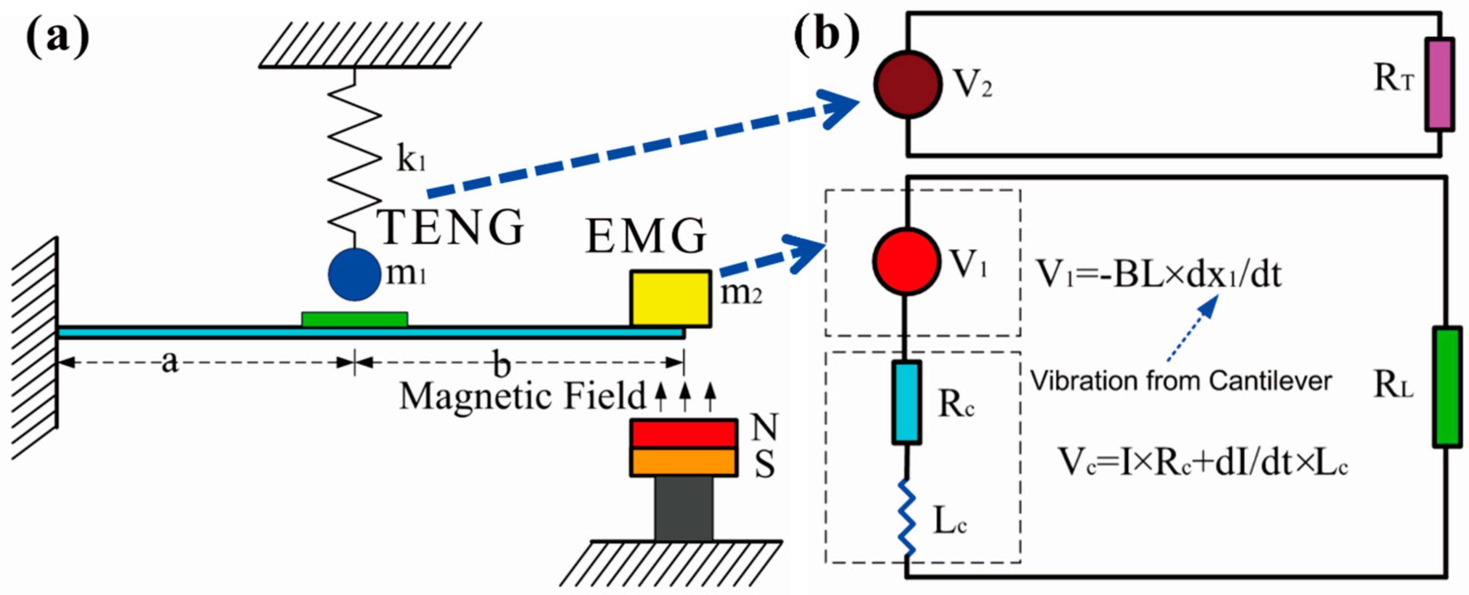
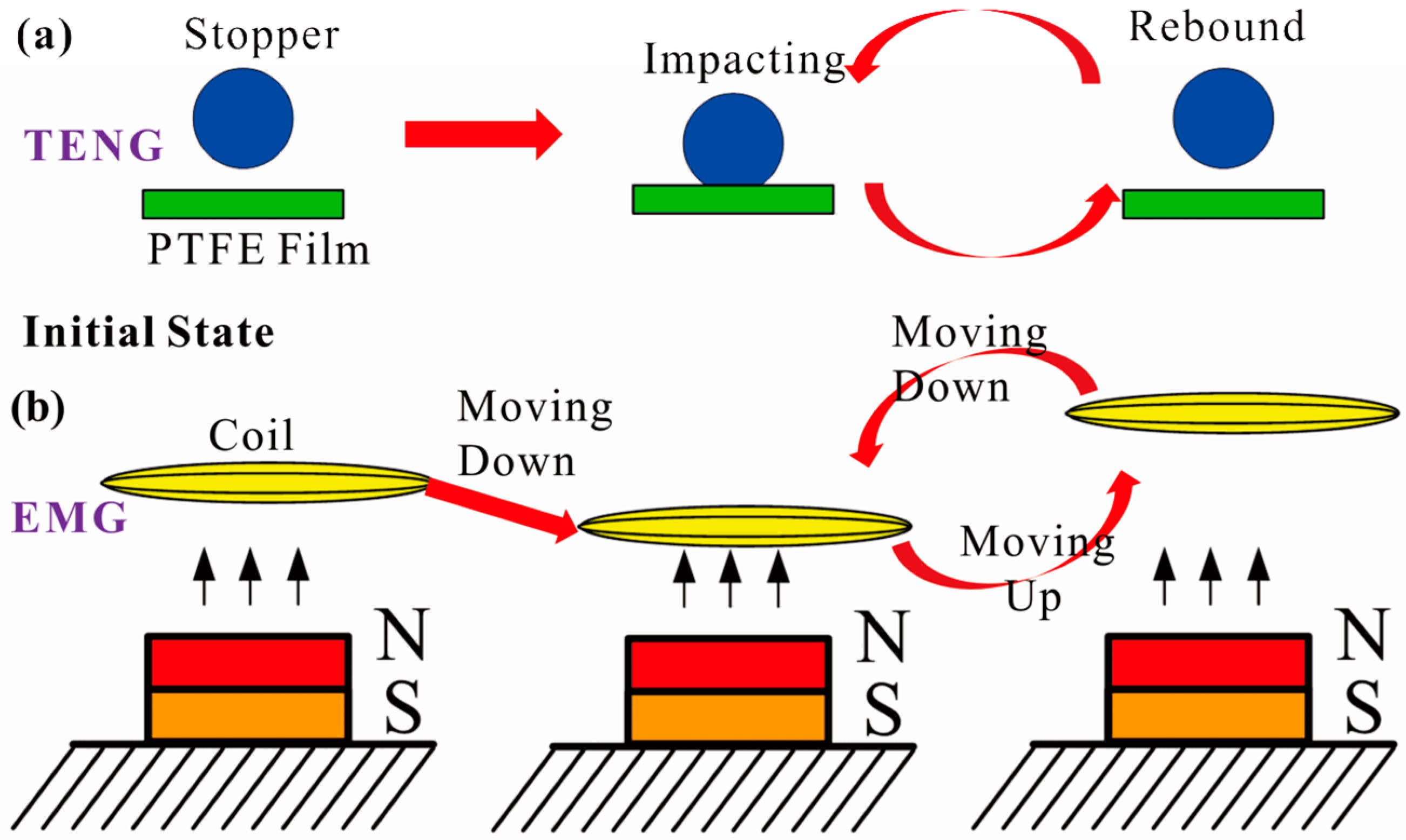
2. System and Design
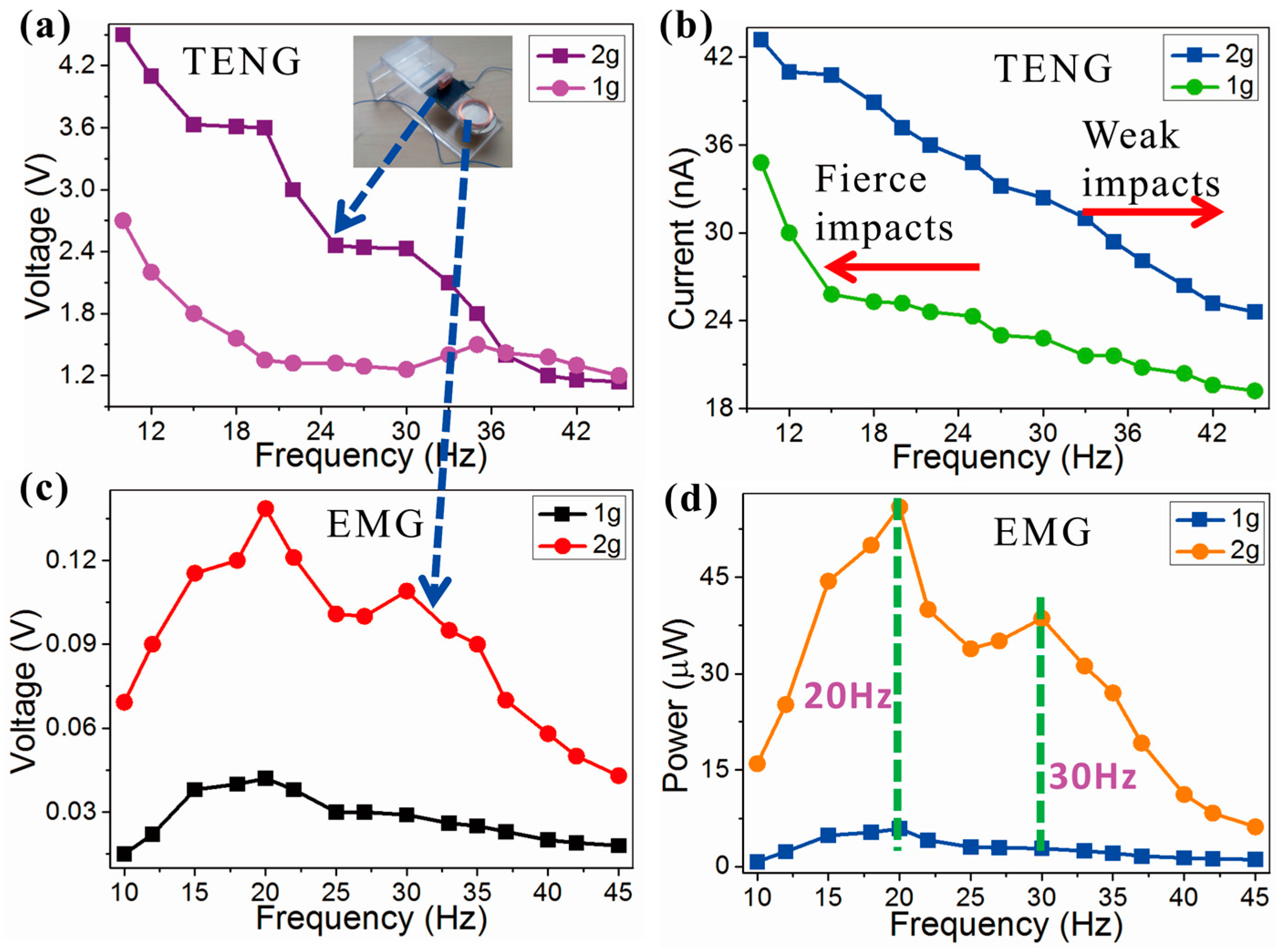
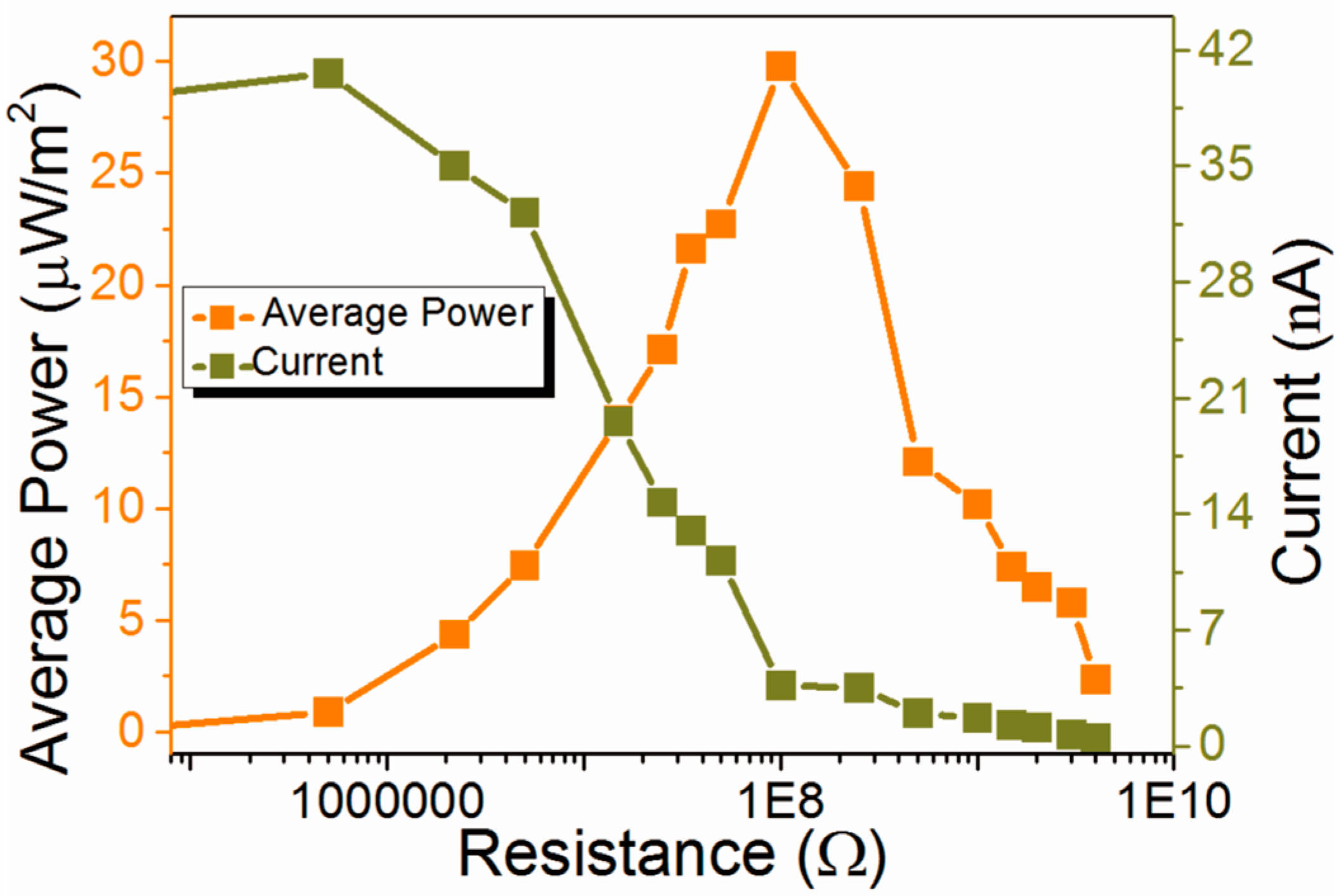
3. Results and Discussion
4. Conclusions
Acknowledgments
Author Contributions
Conflicts of Interest
References
- Ando, B.; Baglio, S.; Trigona, C.; Dumas, N.; Latorre, L.; Nouet, P. Nonlinear mechanism in MEMS devices for energy harvesting applications. J. Micromech. Microeng. 2010, 20, 125020. [Google Scholar] [CrossRef]
- Younis, M.I.; Ouakad, H.M.; Alsaleem, F.M.; Ronald Miles, M.; Cui, W. Nonlinear dynamics of MEMS arches under harmonic electrostatic actuation. J. Microelectromech. Syst. 2010, 19, 647–656. [Google Scholar]
- Kim, J.E.; Kim, Y.Y. Power enhancing by reversing mode sequence in tuned mass-spring unit attached vibration energy harvester. AIP Adv. 2013, 3, 072103. [Google Scholar] [CrossRef]
- Qiu, J.; Feng, Z.C. Parameter dependence of the impact dynamics of thin plates. Comput. Struct. 2000, 75, 491–506. [Google Scholar] [CrossRef]
- Umeda, M.; Nakamura, K.; Ueha, S. Analysis of the transformation of mechanical impact energy to electric energy using piezoelectric vibrator. Jpn. J. Appl. Phys. 1996, 35, 3267–3273. [Google Scholar] [CrossRef]
- Yang, Y.; Zhang, H.; Zhong, X.; Yi, F.; Yu, R.; Zhang, Y.; Wang, Z.L. Electret film enhanced triboelectric nanogenerator matrix for self-powered instantaneous tactile imaging. ACS Appl. Mater. Interfaces 2014, 6, 3680–3688. [Google Scholar] [CrossRef] [PubMed]
- Zhang, X.; Wu, L.; Sessler, G.M. Energy harvesting from vibration with cross-linked polypropylene piezoelectrets. AIP Adv. 2015, 5, 077185. [Google Scholar] [CrossRef]
- Zhang, W.M.; Meng, G.; Wei, K.X. Dynamics of nonlinear coupled electrostatic micromechanical resonators under two-frequency parametric and external excitations. Shock Vib. 2010, 17, 759–770. [Google Scholar] [CrossRef]
- Li, S.; Crovetto, A.; Peng, Z.; Zhang, A.; Hansen, O.; Wang, M.; Wang, F. Bi-resonant structure with piezoelectric PVDF films for energy harvesting from random vibration sources at low frequency. Sens. Actuators A Phys. 2016, 247, 547–554. [Google Scholar] [CrossRef]
- Helseth, L.E.; Guo, X.D. Triboelectric motion sensor combined with electromagnetic induction energy harvester. Sens. Actuators A 2016, 246, 66–72. [Google Scholar] [CrossRef]
- Berdy, D.F.; Srisungsitthisunti, P.; Jung, B.; Xu, X.; Rhoads, J.F.; Peroulis, D. Low-frequency meandering piezoelectric vibration energy harvester. IEEE Trans. Ultrason. Ferroelectr. Freq. Control 2012, 59, 846–858. [Google Scholar] [CrossRef] [PubMed]
- Challa, V.R.; Prasad, M.G.; Shi, Y.; Fisher, F.T. A vibration energy harvesting device with bidirectional resonance frequency tunability. Smart Mater. Struct. 2008, 17, 015035. [Google Scholar] [CrossRef]
- Chen, L.; Jiang, W. A piezoelectric energy harvester based on internal resonance. Acta Mech. Sin. 2015, 31, 223–228. [Google Scholar] [CrossRef]
- Abed, I.; Kacem, N.; Bouhaddi, N.; Bouazizi, M.L. Multi-modal vibration energy harvesting approach based on nonlinear oscillator arrays under magnetic levitation. Smart Mater. Struct. 2015, 25, 025018. [Google Scholar] [CrossRef]
- Olszewski, O.Z.; Houlihan, R.; Mathewson, A.; Jackson, N. A low frequency MEMS energy harvester scavenging energy from magnetic field surrounding an AC current-carrying wire. J. Phys. Conf. Ser. 2016, 757, 012039. [Google Scholar] [CrossRef]
- Yang, B.; Lee, C. Non-resonant electromagnetic wideband energy harvesting mechanism for low frequency vibrations. Microsyst. Technol. 2010, 16, 961–966. [Google Scholar] [CrossRef]
- Yuksek, N.S.; Feng, Z.C.; Almasri, M. Broadband electromagnetic power harvester from vibrations via frequency conversion by impact oscillations. Appl. Phys. Lett. 2014, 105, 113902. [Google Scholar] [CrossRef]
- Salauddin, M.; Halim, M.A.; Park, J.Y. A magnetic-spring-based, low-frequency vibration energy harvester comprising a dual halbach array. Smart Mater. Struct. 2016, 25, 095017. [Google Scholar] [CrossRef]
- Jung, S.M.; Yun, K.S. Energy-harvesting device with mechanical frequency-up conversion mechanism for increased power efficiency and wideband operation. Appl. Phys. Lett. 2010, 96, 111906. [Google Scholar] [CrossRef]
- Mahmoudi, S.; Kacem, N.; Bouhaddi, N. Enhancement of the performance of a hybrid nonlinear vibration energy harvester based on piezoelectric and electromagnetic transductions. Smart Mater. Struct. 2014, 23, 075024. [Google Scholar] [CrossRef]
- Guo, H.; Wen, Z.; Zi, Y.; Yeh, M.H.; Wang, J.; Zhu, L.; Wang, Z.L. A water-proof triboelectric-electromagnetic hybrid generator for energy harvesting in harsh environments. Adv. Energy Mater. 2016, 6, 1501593. [Google Scholar] [CrossRef]
- Han, M.; Zhang, X.; Liu, W.; Sun, X.; Peng, X.; Zhang, H. Low-frequency wide-band hybrid energy harvester based on piezoelectric and triboelectric mechanism. Sci. China Technol. Sci. 2013, 56, 1835–1841. [Google Scholar] [CrossRef]
- Halim, M.A.; Park, J.Y. Piezoceramic based wideband energy harvester using impact-enhanced dynamic magnifier for low frequency vibration. Ceram. Int. 2015, 41, S702–S707. [Google Scholar] [CrossRef]
- Halim, M.A.; Khym, S.; Park, J.Y. Frequency up-converted wide bandwidth piezoelectric energy harvester using mechanical impact. J. Appl. Phys. 2013, 114, 044902. [Google Scholar] [CrossRef]
- Halim, M.A.; Kim, D.H.; Park, J.Y. Low frequency vibration energy harvester using stopper-engaged dynamic magnifier for increased power and wide bandwidth. J. Electr. Eng. Technol. 2016, 11, 707–714. [Google Scholar] [CrossRef]
- Fan, F.R.; Tang, W.; Yao, Y.; Luo, J.; Zhang, C.; Wang, Z.L. Complementary power output characteristics of electromagnetic generators and triboelectricgenerators. Nanotechnology 2014, 25, 135402. [Google Scholar] [CrossRef] [PubMed]
- Zhang, K.W.; Wang, X.; Yang, Y.; Wang, Z.L. Hybridized electromagnetic–triboelectric nanogenerator for scavenging biomechanical energy for sustainably powering wearable electronics. ACS Nano 2015, 9, 3521–3529. [Google Scholar] [CrossRef] [PubMed]
- Salauddin, M.; Park, J.Y. A handy motion driven hybrid energy harvester: Dual halbach array based electromagnetic and triboelectric generators. J. Phys. Conf. Ser. 2016, 773, 012004. [Google Scholar] [CrossRef]
- Gupta, R.K.; Shi, Q.F.; Dhakar, L.; Wang, T.; Heng, C.H.; Lee, C.K. Broadband energy harvester using Non-linear polymer spring and electromagnetic/triboelectric hybrid mechanism. Sci. Rep. 2017, 7, 41396. [Google Scholar] [CrossRef] [PubMed]
- Salauddin, M.; Rasel, M.; Kim, J.W.; Park, J.Y. Design and experiment of hybridized electromagnetic-triboelectric energy harvester using halbach magnet array from handshaking vibration. Energy Convers. Manag. 2017, 153, 1–11. [Google Scholar] [CrossRef]
- Hassan, O.A. A simplified structural analysis of statically indeterminate continuous thick beams. Int. J. Mech. Eng. Educ. 2016, 44, 257–271. [Google Scholar] [CrossRef]
- Niu, S.M.; Wang, S.H.; Lin, L.; Liu, Y.; Zhou, Y.S.; Hua, Y.F.; Wang, Z.L. Theoretical study of contact-mode triboelectric nanogenerators as an effective power source. Energy Environ. Sci. 2013, 6, 3576–3583. [Google Scholar] [CrossRef]


| Modeling Parameters | Symbols | System | Unit |
|---|---|---|---|
| Cantilever Beam Length | L | 6 | cm |
| Cantilever Beam Width | W | 2 | cm |
| Cantilever Beam Thickness | H | 1 | mm |
| Young’s Module | E | 3 | GPa |
| Oscillator Resonant Frequency | f1 | 8 | Hz |
| Cantilever Resonant Frequency | f2 | 74.5 | Hz |
| Coil Turns | N | 100 | 1 |
| Coil Mass | m | 2.1 | g |
| Coil Resistance | Rc | 40 | Ω |
| Load Resistance | Rl | 40 | Ω |
| Oscillator Mass | m1 | 1.9 | g |
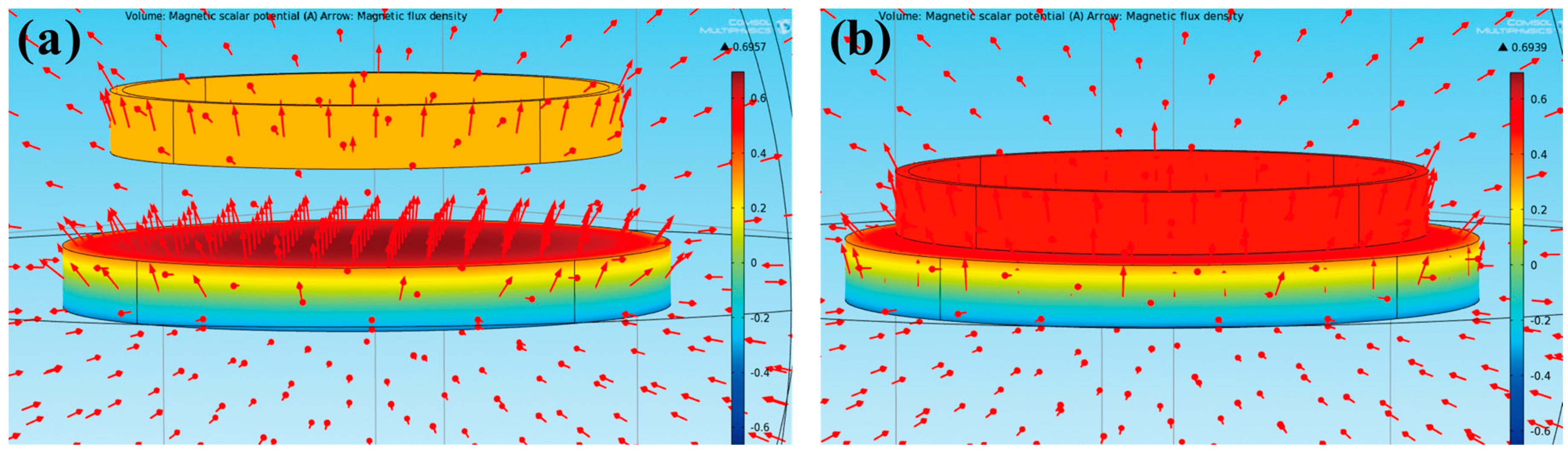
| Magnetic Flux | B | 0.695 | T |
| Magnetic Flux Coefficient on y | cm | 0.0175 | T/mm |
© 2017 by the authors. Licensee MDPI, Basel, Switzerland. This article is an open access article distributed under the terms and conditions of the Creative Commons Attribution (CC BY) license (http://creativecommons.org/licenses/by/4.0/).
Share and Cite
Zhu, J.; Wang, A.; Hu, H.; Zhu, H. Hybrid Electromagnetic and Triboelectric Nanogenerators with Multi-Impact for Wideband Frequency Energy Harvesting. Energies 2017, 10, 2024. https://doi.org/10.3390/en10122024
Zhu J, Wang A, Hu H, Zhu H. Hybrid Electromagnetic and Triboelectric Nanogenerators with Multi-Impact for Wideband Frequency Energy Harvesting. Energies. 2017; 10(12):2024. https://doi.org/10.3390/en10122024
Chicago/Turabian StyleZhu, Jianxiong, Aochen Wang, Haibing Hu, and Hua Zhu. 2017. "Hybrid Electromagnetic and Triboelectric Nanogenerators with Multi-Impact for Wideband Frequency Energy Harvesting" Energies 10, no. 12: 2024. https://doi.org/10.3390/en10122024
APA StyleZhu, J., Wang, A., Hu, H., & Zhu, H. (2017). Hybrid Electromagnetic and Triboelectric Nanogenerators with Multi-Impact for Wideband Frequency Energy Harvesting. Energies, 10(12), 2024. https://doi.org/10.3390/en10122024