1. Introduction
Energy has always played an important role in the survival of mankind, the development of societies and economies, and the strengthening of national security, among others [
1]. Given its abundant supply all over the world and its good comprehensive utilization performance, oil shale is an unconventional oil and gas resource that has been widely utilized as a supplement to conventional energy resources [
2,
3,
4,
5]. Oil shale is mainly extracted via open cast mining and underground mining, both of which are classified as excavation mining methods. Open-cast mining requires a large amount of arable land and can greatly damage the environment, while underground mining in thin oil shale deposits is usually expensive [
3,
6,
7,
8]. With the emergence of the in-situ mining method, oil shale can directly produce shale oil and gas underground, thereby reducing environmental pollution. The in-situ mining method is best used for extracting high-grade oil shale deposits because of its comprehensive benefits [
9].
In addition to the aforementioned methods, borehole hydraulic mining technology may also be used for extracting underground oil shale and is ideally used for extracting deep and low-grade oil shale deposits [
9,
10,
11,
12].
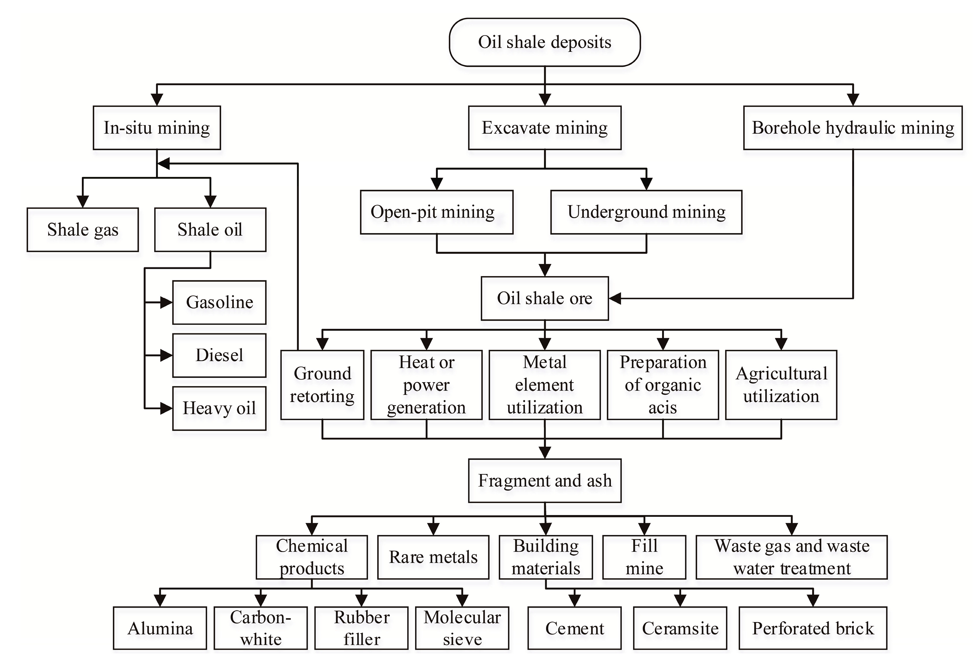
Figure 1 shows the oil shale mining and comprehensive utilization methods. The nozzle is an important executive component in borehole hydraulic mining of oil shale as its jet hydraulic characteristics can directly influence the mining effect. The mining parameters also play crucial roles in the mining process. This study aims to determine the optimal structure of straight cone nozzles and the optimal parameters for borehole hydraulic mining of Huadian oil shale in China.
2. Overview of the Borehole Hydraulic Mining Technology
In borehole hydraulic mining, hydraulic coal mining and high-pressure jet grouting technologies follow the same basic principles of using high-pressure jets to break the ore bed or the rock and soil mass [
13,
14,
15]. Borehole hydraulic mining technology is used for the in-situ mining of underground ore. This technology does not need to remove the overlying strata and offers many other advantages, such as its simple and easy operation, safety, reliability, and role in economic and environmental protection. Therefore, borehole hydraulic mining technology has a very important application value and prospect in engineering practice.
Figure 2 presents a schematic diagram of the borehole hydraulic mining technology.
Using borehole hydraulic mining technology for mining underground oil shale usually involves three steps. First, a borehole must be drilled from the ground down, through the oil shale bed, by using a rig and bit. Second, a hydraulic monitor and other hydraulic mining equipment must be placed down into the borehole from the ground, where the high-pressure pump is then turned on to deliver high-pressure water from the ground, flowing downward along the center hole of the hydraulic monitor. The nozzle is connected to the end of the hydraulic monitor, whereupon the high-pressure water jet ejected by the nozzle can break the underground oil shale bed into several small pieces and then peel them off from the parent rock to produce a mixed solid–liquid, two-phase, flowable ore slurry at the bottom of the borehole. Third, a pneumatic or hydraulic lifting device should be used to lift the ore slurry to the surface.
The breaking of the oil shale into small pieces is the most critical step in the whole process as it ensures the smooth operation of the other mining steps. The effective distance of the high-pressure water jet to break the oil shale can directly determine the effective exploitation of underground oil shale deposits.
3. Design Principles of Straight Cone Nozzle
The straight cone nozzle is a high efficiency nozzle with an excellent jet performance. Apart from its flow coefficient—which can reach as high as 0.98, the straight cone nozzle may be applied for high-pressure jet grouting, firefighting, and hydraulic coal mining, among others [
14,
15,
16,
17]. This type of nozzle may also be used under an injection pressure ranging from 10–60 MPa (maximum pump pressure), which is exactly the driving pressure range of the water jet during the hydraulic mining process, making the straight cone nozzle frequently used in hydraulic mining operations [
16,
17]. Several researchers have carried out studies on the structural optimization of the straight cone nozzle based on numerical simulation by FLUENT software. However, their results and conclusions have not been verified by other experiments [
18,
19,
20]. In addition, there have been no reports on experimental research using a high-pressure water jet, produced by a straight cone nozzle, to break oil shale.
3.1. Structural Parameters of the Straight Cone Nozzle
The straight cone nozzle was invented by the former Soviet Union scholar G. P. Nikonov. The basic characteristics of this nozzle include a contraction angle of
θ = 13° and a cylinder length to outlet diameter ratio (length to diameter ratio) of
l/
d = 2–4. However, the structural parameters of the straight cone nozzle may change under some application conditions [
16,
17]. From the aspect of nozzle manufacturing, a smaller contraction angle corresponds to a more challenging manufacturing process.
In some ways, the structure of the conical nozzle is quite similar to the straight cone nozzle. Their main difference, however, is the structure of the exit section. The conical nozzle has no the exit section. According to previous research [
16,
17], under the same operating conditions, the parameters of the straight cone nozzle and the conical nozzle are also the same, but the former has better jet performance.
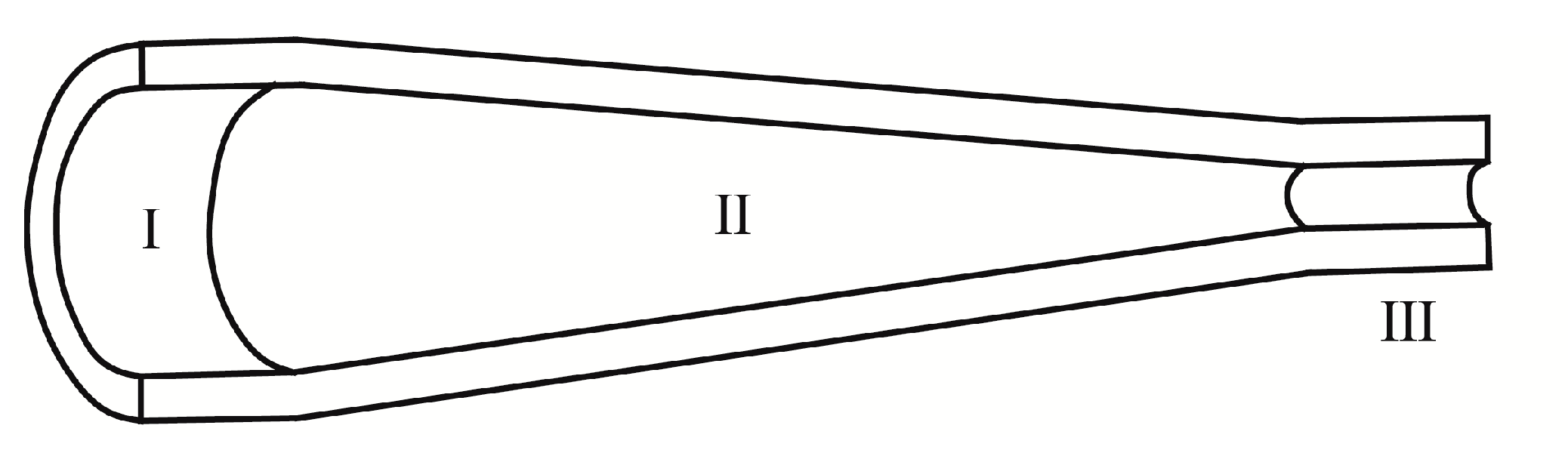
Figure 3 presents a cutaway view of the 3D model of the straight cone nozzle. The straight cone nozzle can be divided into three parts: the access section (I), the contraction section (II), and the exit section (III). The access section is connected to a high-pressure pipeline.
Figure 4 presents a schematic diagram of the straight cone nozzle structure.
The structural parameters of the straight cone nozzle mainly include the inlet diameter, outlet diameter, length of the contraction section, length of the exit section, and length of the access section (
l’, it has no direct effect on the jet performance of the nozzle, and its value can be matched by the length of the connecting section of the high-pressure pipeline). The structural design of the straight cone nozzle must comply with the following equation:
where
D is the inlet diameter,
d is the outlet diameter,
L is the length of the contraction section,
l is the length of the exit section, and
θ is the contraction angle.
3.2. Basic Principle of the Orthogonal Experimental Design
An orthogonal experimental design can be applied in the scientific arrangement and analysis of multifactor experiments through the rational use of the orthogonal table [
21,
22,
23]. The orthogonal table may also be called an orthogonal array, which is written as
Ln(
mk), where
n is the number of rows in the orthogonal table that indicates the number of experiments to be arranged,
k is the number of columns in the orthogonal table that indicates the number of factors, and
m is the number of levels of each factor in the orthogonal table. The orthogonal table is the basic tool of this experimental design which follows a notion of balanced distribution and applies combinatorial mathematics theory to create a mathematical form. The same notion is placed at the core of the orthogonal table [
21].
The process of orthogonal experimental design can be divided into two parts: the experimental design and the data processing [
21,
22,
23]. The experimental design follows five basic steps: (1) clarify the purpose of the experiment and determine the evaluation index, (2) select the factors and determine their level, (3) reasonably complete the type of orthogonal table and the design of the header, (4) clarify the experimental scheme, perform the experiments, and obtain the results, and (5) perform a statistical analysis of the experimental results, conduct validation experiments, and conduct further analyses.
3.3. Structural Design of the Straight Cone Nozzle Based on the Orthogonal Experimental Design
First, the appropriate orthogonal table must be selected. According to its structural characteristics, the straight cone nozzle mainly includes three factors, with each factor having three levels.
Table 1 lists all factors and levels of the orthogonal experimental design of the straight cone nozzle. Given that this orthogonal experiment comprises three levels, the
Ln(3
k) is used as the orthogonal table. Moreover, given that the experiment only has three factors and does not consider the interaction among them, an orthogonal table of
m ≥ 3 is chosen and the
L9(3
4) is used as the smallest orthogonal table of
Ln(3
k) to satisfy the condition
m ≥ 3. As such, the orthogonal table
L9(3
4) is chosen to design the straight cone nozzle structure.
Second, the table header design of the orthogonal experiment must be evaluated. Given that the interaction among different factors is not considered in the experimental design, those factors that are arranged at the position corresponding to the column number above the orthogonal table
L9(3
4) are only needed to determine the table header design required for the orthogonal experiment.
Table 2 lists the contents of the table header. The empty column, also known as the error column, does not place a factor or an interaction and does not affect the results of the orthogonal experimental design. The table must have at least one empty column [
23].
Third, the orthogonal experimental design scheme of the straight cone nozzle must be determined.
Table 3 presents the final orthogonal experimental design scheme. Nine different design schemes are obtained. In addition, by taking into account the dimensions of high-pressure hoses and the machining method of the straight cone nuzzle in this experimental study, the parameters of the straight cone nozzle include the inlet diameter (
D) set as 19 mm, and the length of the access section (
l’) set as 32 mm.
4. Multifunctional Experimental Device for Testing the Performance of High-Pressure Water Jet Breaking Oil Shale
To optimize the structure of the straight cone nozzle and the parameters of the borehole hydraulic mining technology through laboratory experiments, the multifunctional experimental device was independently developed by us to test the performance of the high-pressure water jet breaking oil shale.
Figure 5 shows the multifunctional experimental device, which mainly comprises five systems: the experimental bench, the power system of the water jet, the control and detection system, the fastening and motion system, and the fluid circulation system [
13,
24].
Table 4 lists the main functions and components of these five systems. The rated pressure of the high-pressure pump is 15 MPa and the maximum injection distance can be adjusted to 930 mm.
5. Experimental Study of the Jet Performance of the Straight Cone Nozzle Breaking Oil Shale
5.1. Experimental Research on the Jet Performance of the Straight Cone Nozzle
The jet performance of the straight cone nozzles with different structures was evaluated based on the high-pressure water jet’s impact force under the same experimental conditions.
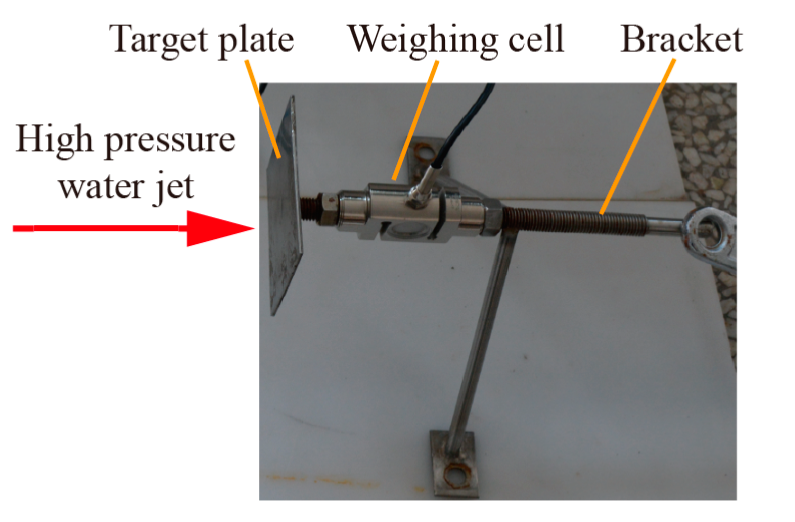
Figure 6 shows the detection mechanism of the water jet’s impact force, which is fixed in the angle-adjustable sample basket and is mainly composed of a target plate, weighing cell, and bracket. When the high-pressure water jet impacts the target plate, the weighing cell can be used to detect the real-time value of the water jet impact force.
Figure 7 shows the force analysis model of the high-pressure water jet impact on the target plate.
The injection angle of the high-pressure water jet is computed as the angle between the direction of injection and the vertical axis of the target plate. The high-pressure water jet impact force on the target plate can be calculated as follows:
where
F is the high-pressure water jet impact force on the target plate,
Fn is the component force of
F in the vertical direction of the target plate,
φ is the angle between the high-pressure water jet and the target plate,
ρ is the density of water,
Q is the flow of water, and
u is the velocity of the high-pressure water jet.
When
φ = 90° is the maximum value of
F, the corresponding injection angle is 0°. The high-pressure water jet cutting and breaking depth of the material is inversely proportional to the injection angle. Under certain operating conditions, the maximum cutting and breaking depth can be obtained when the high-pressure water jet impacts the surface of the material vertically and while the corresponding injection angle is 0° [
13,
16,
17,
25].
Using the orthogonal experimental design in
Table 3, the jet performance of straight cone nozzles with different structures, when tested under the experimental conditions include that the injection pressure is 15 MPa, injection distance is 930 mm, and injection angle is 0°. The impact force of the high-pressure water jet that is produced by nine groups of straight cone nozzles with different structures is calculated based on the orthogonal experimental design.
Figure 8 shows the related data.
5.2. Analysis of Experimental Results of Jet Performance of the Straight Cone Nozzle
The impact force tested above is subjected to the range analysis.
Table 5 shows the related data.
Table 5 shows a range order of
RA >
RC >
RB. Thus, the factors are arranged as follows from primary to secondary: A (outlet diameter d), C (contraction angle
θ), and B (length to diameter ratio
l/
d). The optimal scheme of the straight cone nozzle is written as A
3B
2C
1, with an outlet diameter of
d = 4 mm, length to diameter ratio of
l/
d = 2.5, and contraction angle of
θ = 60°. This optimal scheme is the structure of the ninth straight cone nozzle based on the orthogonal experimental design.
To verify the appropriateness of the selected factors and levels for the above orthogonal experimental design, and to check whether a better design scheme exists, the factors and levels of the orthogonal experimental design were used as the abscissa, while the average value of the experimental index
ki was used as the ordinate to draw a trend chart of the impact force of the high-pressure water jet produced by straight cone nozzles with different structures.
Figure 9 presents the trend chart.
The maximum impact force of the high-pressure water jet produced by the straight cone nozzle has an outlet diameter of
d = 4 mm, length to diameter ratio of
l/
d = 2.5, and contraction angle of
θ = 60°. The optimal scheme of the straight cone nozzle is still A
3B
2C
1.
Figure 9 shows three main points. First, an increase in outlet diameter
d corresponds to an increase in the impact force of the high-pressure water jet. Second, when the length to diameter ratio
l/
d increases, the impact force of the high-pressure water jet initially increases and then decreases without showing any significant changes. Third, an increase in the contraction angle
θ corresponds to a decrease in the impact force of the high-pressure water jet.
The variance analysis was performed to estimate further the significance of each factor to the experimental results.
Table 6 presents the related data. Factor A (outlet diameter
d) has a very significant influence on the experimental results, while factor C (contraction angle
θ) only has a small influence. Given that the mean square value of factor B (length to diameter ratio
l/
d) is less than that of the empty column, this factor is classified as an error term that has a small influence on the experimental results. Therefore, the primary and secondary orders of each factor, as obtained in the variance analysis, are consistent with the range analysis results.
5.3. Experimental Study of Oil Shale Breaking
The oil shale samples for this study are all taken from Huadian area in Jilin Province, China.
Table 7 shows the mechanical properties of these samples [
26]. It is necessary to note that the mechanical properties of the oil shale in Huadian listed in
Table 7 are based on the cores drilled in the field, but the oil shale samples in laboratory, transported from the field site, will be affected by weathering in transit, and their mechanical properties will be lower than before. In addition, due to oil shale having a very obvious stratification (schistosity) characteristic, it is very difficult to drill the core to test its mechanical properties from the weathered oil shale sample [
13].
The parameters of the borehole hydraulic mining technology mainly include injection pressure (injection flow), injection distance, and injection direction. The external environment of the water jet has a great influence on the broken oil shale. The straight cone nozzle produces a continuous straight water jet according to [
16], and the effective injection distance of the straight cone nozzle is 100 to 150 times longer than the outlet diameter when a non-submerged jet is used. However, the effective injection distance of the straight cone nozzle is only 5 to 8 times longer than the outlet diameter when a submerged jet is used.
Given the inherent spray splash phenomenon and that the duration of the experiment was too short when testing the best-performing jet of the straight cone nozzle (A
3B
2C
1), aspects of the oil shale breaking process remain unclear. Another straight cone nozzle with poor jet performance should be used to break an oil shale sample.
Table 8 presents the structural parameters of the straight cone nozzle, and
Table 9 presents the experimental parameters.
Considering of the schistosity of oil shale and its obvious bedding development, the experiment can be divided into parallel bedding direction impacts and vertical bedding direction impacts.
Figure 10,
Figure 11,
Figure 12 and
Figure 13 show the experimental processes, which can be described as follows. First,
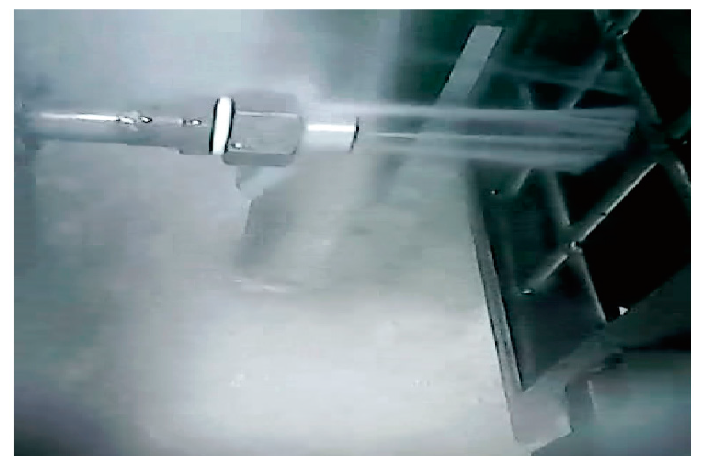
Figure 10 shows whether the surface of the oil shale is impacted by the high-pressure water jet in the parallel or vertical bedding direction. The high-pressure water jet impacts the surface of the oil shale, splashes around, and forms a water mist.
Second, when the jet is in the parallel bedding direction, the high-pressure water jet cuts into the oil shale upon impacting its surface. Instead of splashing around, the jet is reflected back along the crack on a vertical plane, as shown in
Figure 11.
Third, the oil shale is removed from the sample basket and leveled on the ground. When the jet is in the parallel bedding direction, a circular hole emerges from the jet impact point and is treated as the base point. Starting from this base point, the crack extends along the stratification of oil shale upward and downward, and then the oil shale is broken into two parts, as shown in
Figure 12.
Fourth, although a broken pit can be generated at the impact point on the oil shale surface when the water jet is in the direction of the vertical bedding of oil shale, the whole of the oil shale is not completely broken, as shown in
Figure 13.
5.4. Analysis of Experimental Results of Broken Oil Shale
From these results, we can conclude that is easier to break oil shale when the high-pressure water jet is in the parallel bedding direction than when the jet is in the vertical bedding direction of the oil shale. The oil shale’s schistosity structure and obvious bedding characteristics are the main reason for this result. After a circular hole emerges from the jet impact point when the high-pressure water jet is in the parallel bedding direction, the continuous impact of the water jet can produce a strong water wedge effect on the hole, which will be conducive to the extension and connectivity of the crack.
6. Discussion
Based on the orthogonal experimental design, the optimal structural design scheme of the straight cone nozzle is A3B2C1. The oil shale can be easily broken when the jet is in the parallel bedding direction.
These findings have two implications. First, the impact force of the high-pressure water jet produced by the straight cone nozzle varies with its different structures, such that the straight cone nozzle has the optimal structure. Second, the injection direction of the high-pressure water jet influences the oil shale breaking. Therefore, the parameters of the straight cone nozzle and the borehole hydraulic mining technology must be optimized to meet these parameters.
These results and conclusions provide a valuable reference for borehole hydraulic mining of oil shale in Huadian. To enhance the efficiency of borehole hydraulic mining as much as possible, a non-submerged jet should be used, the strength of the pumping slurry in the borehole should be increased, and the mining and pumping slurry should become independent from each other using a butted well (i.e., one end of the well is used for mining, while the other end is used for pumping).
However, this study has some limitations. First, the influence of confining pressure on oil shale breaking by a high-pressure water jet is not considered. Second, the oil shale from Huadian are only used in the breaking experiments, so these findings may not apply for oil shale extracted from other areas.
Further research should keep two main considerations in mind. First, the multifunctional experimental device can be improved to increase the function of confining pressure to the oil shale sample surface, a function that can be achieved by hydraulic pressure or air pressure loading. Second, the oil shale sample for experimental research could be selected from different areas, so that the experimental results and conclusions can be generalized.
The optimal structural parameters of the straight cone nozzle include an outlet diameter of d = 4 mm, a length to diameter ratio of l/d = 2.5, and a contraction angle of θ = 60°. The high-pressure water jet should be parallel to the oil shale bedding during borehole hydraulic mining.
7. Conclusions
- (1)
The self-developed multifunctional experimental device can meet the requirements of the jet characteristics testing of the straight cone nozzles and the oil shale breaking experiments.
- (2)
Based on the comprehensive results of the orthogonal experimental design, range analysis, and variance analysis, the optimal structural parameters of the straight cone nozzle can be obtained as follows: outlet diameter is d = 4 mm, length to diameter ratio is l/d = 2.5, and contraction angle is θ = 60°.
- (3)
To maximize the efficiency of borehole hydraulic mining of oil shale, a non-submerged jet should be placed parallel to the oil shale bedding. The experimental results and conclusions provide valuable scientific references for borehole hydraulic mining of oil shale in Huadian area. Further research may reference these values for the exploitation of oil shale in other areas.
Acknowledgments
This study was supported by the Project of National Natural Science Foundation of China (Grant No. 41602371), the key projects of Sichuan Provincial Department of Education (Grant No. 17ZA0028), the Open Research Project of Ministry of Land and Resources Key Laboratory of Drilling and Exploitation Technology in Complex Condition (Grant No. DET201615), the Open Research Fund Program of Ministry of Education Key Laboratory of Metallogenic Prediction of Nonferrous Metals and Geological Environment Monitoring (Grant No. 2017YSJS03). This support is greatly appreciated.
Author Contributions
For this paper, Jiwei Wen conducted the laboratory tests, analyzed the data and wrote the paper; Chen Chen put forward study ideas and conducted the experiments.
Conflicts of Interest
The content of the paper is original and on behalf of all the authors, I can confirm that this material has not been published elsewhere and the authors have no conflict of interest.
References
- Jiang, Z.M. Reflections on Energy Issues in China. J. Shanghai Jiaotong Univ. 2008, 42, 345–359. [Google Scholar] [CrossRef]
- Liu, Z.J.; Yang, H.L.; Dong, Q.S.; Zhu, J.W.; Guo, W. Oil Shale in China; Petroleum Industry Press: Beijing, China, 2009. [Google Scholar]
- Qian, J.L.; Yin, L. Oil Shale-Supplement Energy Resources for Petroleum; China Petrochemical Press: Beijing, China, 2008. [Google Scholar]
- Brendow, K. Global Oil Shale Issues and Perspectives. Oil Shale 2003, 20, 81–92. [Google Scholar]
- Liu, R.; Liu, Z.J. Oil Shale Resource Situation and Multi-Purpose Development Potential in China and Abroad. J. Jilin Univ. (Earth Sci. Ed.) 2006, 36, 892–898. [Google Scholar]
- Shi, G.Q. Oil Shale and Shale Oil; China Petrochemical Press: Beijing, China, 2009. [Google Scholar]
- Wang, H.Y.; Liu, Z.W.; Ning, N. Oil Shale Resources and Development Technology; Petroleum Industry Press: Beijing, China, 2010. [Google Scholar]
- Valgma, I. Oil Shale Mining-Related Research in Estonia. Oil Shale 2009, 26, 445–450. [Google Scholar] [CrossRef]
- Chen, C.; Sun, Y.H. Mining Mode for Oil Shale. Explor. Eng. (Rock Soil Drill. Tunn.) 2010, 37, 26–29. [Google Scholar]
- Chen, C.; Zhang, Z.P.; Wang, M. New Mining Mode for Oil Shale in Jilin. China Min. Mag. 2007, 16, 55–57. [Google Scholar]
- Yan, X.C.; Chen, C.; Liu, X.P.; Zhang, Q. Physical and Mechanical Parameters of Borehole Hydraulic Mining of Nong’an Oil Shale. Oil Shale 2012, 29, 237–247. [Google Scholar]
- Zhao, G.J.; Chen, C.; Dong, X.J.; Qian, F.; Wang, W.; Gao, S. Application of FLAC3D for Simulation of the Borehole Hydraulic Mining of Nong’an Oil Shale. Oil Shale 2014, 31, 278–288. [Google Scholar] [CrossRef]
- Wen, J.W. Numerical Simulation and Experimental Research on the Jet Devices for Borehole Hydraulic Mining of Oil Shale. Ph.D. Thesis, Jilin University, Changchun, China, June 2014. [Google Scholar]
- Wen, J.W.; Pei, X.J.; Wang, W.C.; He, Z.H. Discussion on Several Problems of High Pressure Jet Grouting in Seepage Prevention and Reinforcement. Explor. Eng. (Rock Soil Drill. Tunn.) 2016, 43, 56–62. [Google Scholar]
- Lu, Y.Y.; Zhou, Z.; Ge, Z.L.; Zhang, X.W.; Li, Q. Research on and design of a self-propelled nozzle for the tree-type drilling technique in underground coal mines. Energies 2015, 8, 14260–14271. [Google Scholar] [CrossRef]
- Xue, S.X. High Pressure Water Jet Technology & Engineering; Hefei University of Technology Press: Hefei, China, 2006. [Google Scholar]
- Sun, J.J. Water Jet Cutting Technology; China University of Mining and Technology Press: Xuzhou, China, 1992. [Google Scholar]
- Zhang, S.C.; Tao, X.H.; Lu, J.S.; Wang, X.J.; Zeng, Z.H. Structure optimization and numerical simulation of nozzle for high pressure water jetting. Adv. Mater. Sci. Eng. 2015, 2015, 732054. [Google Scholar] [CrossRef]
- Yang, G.L.; Zhou, W.H.; Liu, F. Simulation of flow field of high-pressure water jet by nozzles based on FLUENT software. J. Lanzhou Univ. Technol. 2008, 34, 49–52. [Google Scholar]
- Chen, C.; Nie, S.L.; Wu, Z.J.; Li, Z.Y. A study of high pressure water jet characteristics by CFD simulation. Mach. Tool Hydraul. 2006, 2, 103–105. [Google Scholar]
- Ren, L.Q. Experimental Design and Optimization; Science Press: Beijing, China, 2009. [Google Scholar]
- Chen, K. Experimental Design and Analysis; Tsinghua University Press: Beijing, China, 2005. [Google Scholar]
- Li, Y.Y.; Hu, C.R. Experimental Design and Data Processing; Chemical Industry Press: Beijing, China, 2008. [Google Scholar]
- Wen, J.W.; Chen, C. Multifunctional Experimental Device of Teaching Model and Its Application of Water Jet Testing and Breaking Rock. Sci. Technol. Eng. 2017, 17, 168–172. [Google Scholar]
- Frank, M.W. Fluid Mechanics, 7th ed.; McGraw-Hill: New York, NY, USA, 2011. [Google Scholar]
- Liu, X.P.; Chen, C.; Yan, X.C.; Zhang, F.Y. Determination of Physical and Mechanical Properties and Crack Opening Pressure in Huadian of Jilin Province. China Min. Mag. 2013, 22, 83–85. [Google Scholar]
Figure 1.
Oil shale mining and comprehensive utilization methods.
Figure 1.
Oil shale mining and comprehensive utilization methods.
Figure 2.
Schematic diagram of the borehole hydraulic mining technology.
Figure 2.
Schematic diagram of the borehole hydraulic mining technology.
Figure 3.
Cutaway view of the 3D model of the straight cone nozzle.
Figure 3.
Cutaway view of the 3D model of the straight cone nozzle.
Figure 4.
Schematic diagram of the straight cone nozzle structure.
Figure 4.
Schematic diagram of the straight cone nozzle structure.
Figure 5.
The multifunctional experimental device for testing the performance of the high-pressure water jet breaking oil shale.
Figure 5.
The multifunctional experimental device for testing the performance of the high-pressure water jet breaking oil shale.
Figure 6.
The detection mechanism of the water jet impact force.
Figure 6.
The detection mechanism of the water jet impact force.
Figure 7.
The force analysis model of the high-pressure water jet impact on the target plate.
Figure 7.
The force analysis model of the high-pressure water jet impact on the target plate.
Figure 8.
The impact force of the high-pressure water jet produced by the straight cone nozzles with different structures based on the orthogonal experimental design.
Figure 8.
The impact force of the high-pressure water jet produced by the straight cone nozzles with different structures based on the orthogonal experimental design.
Figure 9.
Trend chart of the impact force of the high-pressure water jet produced by straight cone nozzles with different structures.
Figure 9.
Trend chart of the impact force of the high-pressure water jet produced by straight cone nozzles with different structures.
Figure 10.
The initial stage of the oil shale breaking.
Figure 10.
The initial stage of the oil shale breaking.
Figure 11.
The high-pressure water jet cutting into the oil shale sample.
Figure 11.
The high-pressure water jet cutting into the oil shale sample.
Figure 12.
The oil shale sample is broken in the parallel bedding direction.
Figure 12.
The oil shale sample is broken in the parallel bedding direction.
Figure 13.
The oil shale sample produces a broken pit on the surface of the vertical bedding.
Figure 13.
The oil shale sample produces a broken pit on the surface of the vertical bedding.
Table 1.
Factors and levels of the orthogonal experimental design for the structural parameters of the straight cone nozzle.
Table 1.
Factors and levels of the orthogonal experimental design for the structural parameters of the straight cone nozzle.
| Levels | Factors |
|---|
| (A) Outlet Diameter d, mm | (B) Length to Diameter Ratio l/d | (C) Contraction Angle θ, ° |
|---|
| 1 | 2 | 2 | 60 |
| 2 | 3 | 2.5 | 90 |
| 3 | 4 | 3 | 120 |
Table 2.
The table header design of the orthogonal experiment for the structural parameters of the straight cone nozzle.
Table 2.
The table header design of the orthogonal experiment for the structural parameters of the straight cone nozzle.
| Factors | A | Empty Column | B | C |
|---|
| Column number | 1 | 2 | 3 | 4 |
Table 3.
The final orthogonal experimental design scheme of the straight cone nozzle structure parameters.
Table 3.
The final orthogonal experimental design scheme of the straight cone nozzle structure parameters.
| Experimental Number | Factors |
|---|
| A | Empty Column | B | C |
|---|
| 1 | 1 | 1 | 1 | 1 |
| 2 | 1 | 2 | 2 | 2 |
| 3 | 1 | 3 | 3 | 3 |
| 4 | 2 | 1 | 2 | 3 |
| 5 | 2 | 2 | 3 | 1 |
| 6 | 2 | 3 | 1 | 2 |
| 7 | 3 | 1 | 3 | 2 |
| 8 | 3 | 2 | 1 | 3 |
| 9 | 3 | 3 | 2 | 1 |
Table 4.
The main functions and components of the five systems of the multifunctional experimental device.
Table 4.
The main functions and components of the five systems of the multifunctional experimental device.
| Number | Main Systems | Main Functions | Main Components |
|---|
| 1 | Experimental bench | The main frame structure of the experimental device | (1) The upper experimental bench
(2) The lower experimental bench |
| 2 | Power system of the water jet | The power source of the water jet and the executive element | (1) Electric source and electric cables
(2) High-pressure pump
(3) High-pressure hose
(4) Straight cone nozzle |
| 3 | Control and detection system | Changes and controls the working condition of the water jet (such as injection pressure, flow, jet distance, and jet angle) as well as displays, detects, and records the parameters of the water jet in real time (such as injection pressure, flow, and jet impact force) | (1) Frequency counters
(2) Servo motor and servo driver
(3) Synchronous belt and synchronous belt wheel
(4) Sensors (such as turbine flowmeter, pressure transmitter, and weighing cell)
(5) Display instruments (such as flow integrating instrument, intelligent digital display instrument, and force display control instrument)
(6) Communication converter
(7) Data acquisition software and computer |
| 4 | Fastening and motion system | The fastening of the oil shale samples and the target plate, which alternately move backward and forward as well as rotate at angles between 0° and 90° | (1) Linear guides and sliders
(2) Angle-adjustable sample basket
(3) Independent sample basket
(4) Hand wheel and angle-adjusting screw
(5) Oil shale sample fixing and adjusting screw |
| 5 | Fluid circulation system | Ensures water supply, filtration, closed cycle, and drain | (1) Water tank
(2) Hose
(3) Setting tank
(4) Pump
(5) Floor drain |
Table 5.
Range analysis of the impact force of the high-pressure water jet produced by straight cone nozzles with different structures.
Table 5.
Range analysis of the impact force of the high-pressure water jet produced by straight cone nozzles with different structures.
| Experimental Number | Factors | Mean Impact Force of the High-Pressure Water Jet, kg |
|---|
| A | Empty Column | B | C |
|---|
| 1 | 1 | 1 | 1 | 1 | 7.28 |
| 2 | 1 | 2 | 2 | 2 | 6.59 |
| 3 | 1 | 3 | 3 | 3 | 6.42 |
| 4 | 2 | 1 | 2 | 3 | 13.35 |
| 5 | 2 | 2 | 3 | 1 | 16.55 |
| 6 | 2 | 3 | 1 | 2 | 15.56 |
| 7 | 3 | 1 | 3 | 2 | 27.78 |
| 8 | 3 | 2 | 1 | 3 | 26.07 |
| 9 | 3 | 3 | 2 | 1 | 30.94 |
| K1 | 20.29 | 53.78 | 48.91 | 54.77 | N/A |
| K2 | 45.46 | 47.72 | 50.88 | 49.93 | N/A |
| K3 | 84.79 | 49.04 | 50.75 | 45.84 | N/A |
| k1 | 6.763 | 17.927 | 16.303 | 18.257 | N/A |
| k2 | 15.153 | 15.907 | 16.960 | 16.643 | N/A |
| k3 | 28.263 | 16.347 | 16.917 | 15.280 | N/A |
| Range (R) | 21.50 | 2.02 | 0.66 | 2.98 | -- |
| Factors (Primary to secondary) | A C B |
| Optimal scheme | A3B2C1 |
Table 6.
Variance analysis of the impact force of the high-pressure water jet produced by straight cone nozzles with different structures.
Table 6.
Variance analysis of the impact force of the high-pressure water jet produced by straight cone nozzles with different structures.
| Difference Source | Sum of Squares of Deviations | Degree of Freedom | Mean Square Value | F Value | Critical Value | Significance |
|---|
| A | 901.453 | 2 | 450.727 | 408.990 | F0.01(2,4) = 18 | Very significant |
| B | 0.073 | 2 | 0.037 | N/A | N/A | N/A |
| C | 6.887 | 2 | 3.443 | 3.125 | F0.01(2,4) = 18 | Not significant |
| Empty column | 4.335 | 2 | 2.167 | N/A | N/A | N/A |
| Error | 4.408 | 4 | 1.102 | N/A | N/A | N/A |
| Summation | 909.905 | 8 | N/A | N/A | N/A | N/A |
| Factors (Primary to secondary) | A C B |
Table 7.
Mechanical properties of the oil shale in Huadian [
26].
Table 7.
Mechanical properties of the oil shale in Huadian [
26].
| Mechanical Properties | Compressive Strength, MPa | Tensile Strength, MPa | Elastic Modulus, MPa | Poisson Ratio | Internal Friction Angle, ° | Cohesive Force, MPa |
|---|
| Value range | 9 to 19 | 0.8 to 1.5 | 216 to 386 | 0.27 to 0.35 | 15 to 33 | 0.7 to 1.5 |
Table 8.
Structural parameters of the straight cone nozzle for the experimental study of oil shale breaking.
Table 8.
Structural parameters of the straight cone nozzle for the experimental study of oil shale breaking.
| Structural Parameters | Inlet Diameter D, mm | Outlet Diameter d, mm | Length to Diameter Ratio l/d | Contraction Angle, ° |
|---|
| Value | 19 | 2 | 2 | 120 |
Table 9.
The experimental parameters.
Table 9.
The experimental parameters.
| Experimental Parameters | Injection Pressure, MPa | Injection Flow, m3/h | Injection Distance, mm | Injection Angle, ° | External Environment | Jet Type |
|---|
| Value | 15 | 1.45 | 200 | 0 | Air | Non-submerged jet |
© 2017 by the authors. Licensee MDPI, Basel, Switzerland. This article is an open access article distributed under the terms and conditions of the Creative Commons Attribution (CC BY) license (http://creativecommons.org/licenses/by/4.0/).


