Article

Experimental Study on Bluff-Body Stabilized Premixed Flame with a Central Air/Fuel Jet

1
Department of Energy Sciences, LTH, Lund University, SE-22100 Lund, Sweden
2
China Aerodynamics Research and Development Center, Mianyang 621000, China
3
Division of Combustion Physics, LTH, Lund University, SE-22100 Lund, Sweden
*
Author to whom correspondence should be addressed.
Energies 2017, 10(12), 2011; https://doi.org/10.3390/en10122011
Submission received: 28 September 2017 / Revised: 22 October 2017 / Accepted: 10 November 2017 / Published: 1 December 2017
(This article belongs to the Section I: Energy Fundamentals and Conversion)

Abstract

:
Bluff-body flame holders are commonly employed in many industrial applications. A bluff-body is usually adopted to enhance the downstream mixing of the combustion products and the fresh fuel-air mixtures, thus to improve the flame stability and to control the combustion process. In the present paper, flames stabilized by a conical-shape bluff-body flame holder with a central air/fuel jet were studied. Effects of both a central air jet and a central fuel jet on the structures and lean blowout limits of the premixed annular flames, and on the temperature on the upper surface of the bluff-body were investigated and presented. It was revealed that a central jet led to a considerable reduction of the temperature on the upper surface of the bluff-body. It was proposed to be caused by the alternation of flow structures (in the case with a central air jet) altogether with the flame lifting from the burner (in the case with a central fuel jet). Thus, it might be used to solve the problem of the bluff-body with high heat loads in practical applications. The flame stability characteristics, for example the unstable flame dynamics and the lean blowout limits, varied with the injection of an air or fuel jet through the central pipe. Different blowout behaviors, being with or without the occurrence of flame split and flashing, caused by a central air jet were presented in the paper. In addition, when a small amount of central fuel jet (i.e., Uf/Ua = 0.045) was injected into the flow fields, an unsteady circular motion of the flame tip along the outer edge of the bluff-body was observed as well. Whereas, with an increase in the amount of the central fuel jet, the flame detached from the outer edge of the bluff-body and then became much more unstable. With a central air or fuel jet injecting into the flow field, premixed flames stabilized by the bluff-body became more unstable and easier to blowout.

1. Introduction

Premixed flame stabilization is of significant practical and technological interest for various industrial combustion systems, such as in gas turbine combustors, afterburners in jet engine and industrial furnaces [1]. There are two main flame stabilization schemes employed in premixed combustion systems, including the use of a swirling flow and the use of a bluff-body. A bluff-body is adopted in premixed flame stabilization due to its simple geometry, the enhanced mixing of reactants and combustion products altogether with the ease of combustion control. Downstream of the bluff-body, the recirculation of hot gases enhances the re-ignition of reactants and thus to stabilize the flame [2]. The practical importance of a stable flame has given rise to a large number of theoretical and experimental studies about the performance of a bluff-body in stabilizing the flame.
A number of seminal works of bluff-body stabilized premixed flame has been carried out by Zukoski [3,4], Longwell [5,6], Wright [7] and Pan [8]. Researchers concerned mainly on the blowout mechanisms and the lean stabilization limits of flames stabilized by a bluff-body. Lefebvre et al. [9] studied the influences of several operating parameters and bluff-body geometries on the lean blowout performances of flames downstream of a bluff-body. It was recommended by Lefebvre et al. [9] and Barrere and Mestre [10] that the characteristic dimension of a bluff-body flame holder should not be its geometric width, but rather the maximum aerodynamic width of the wake created downstream of it. Flame dynamics downstream of a two-dimensional bluff-body were reviewed by Shanbhogue et al. [11]. Based on the description of the blowout process of flames stabilized by a bluff-body, they concluded that blowout occurs in multiple steps, associated with local extinction along the flame sheet and large scale wake disruption, followed by blowout whose ultimate ‘trigger’ is probably associated with wake cooling and shrinking. Chaparro and Baki [12] studied blowout characteristics of bluff-body stabilized conical premixed flames under inlet velocity modulations using three different bluff-body geometries. Flame blowout features in cases with different upstream flow velocities (5, 10 and 15 m/s) and excitation frequencies (from 0 to 400 Hz) were studied. They concluded that the disk-shape bluff-body better stabilized the flame than the rod-shaped bluff-body. It was caused by the higher degree of flow separation and wake recirculation for the disk-shape flame holder. Chaudhuri et al. [13] examined blowout characteristics of premixed flames anchored downstream of a conical-shape bluff-body when the upstream mixture had spatial gradients and velocity oscillations. They revealed that the blowout limits were higher for the confined flame configuration than the un-confined cases. It was also concluded that the fuel enrichment near the flame stabilization region reduced the base blowout equivalence ratios significantly. Flames stabilized by a bluff-body had the features as flames with a central pilot, under which conditions the outer flow was mainly un-burnt due to the locally fuel-lean conditions. Chaudhuri et al. [14] also proposed the blowout mechanisms of premixed flames anchored by a bluff-body. Different flame shapes, including the conical and the columnar shapes, were observed with the alternation in the equivalence ratio. The local extinction and re-ignition of the flame near blowout were reported as well. Combustion characteristics of premixed hydrogen/air flame in a micro-combustor with a bluff body was studied experimentally and numerically by Jianlong et al. [15]. Effects of bluff-body geometry on the lean stabilization limits of premixed hydrogen/air flame in a micro-combustor were investigated numerically by Fan et al. [16] and Bagheri et al. [17]. Fan et al. [16] reported that different flame blowout limits in cases with different bluff-body geometries were caused by the alternation of recirculation zone and flame stretching. The heat lost to the side wall of the confinement was considered to have negligibly weak influences on the blowout limits of a flame. Moreover, Fan et al. [18] also reported that the flame blowout limits were strongly determined by the solid materials of the bluff-body.
In the diffusion flame stabilizations, bluff-bodies with a central jet are commonly seen. Roquemore et al. [19] studied the flow fields in isothermal and reacting cases downstream of an axisymmetric bluff-body. They obtained mixing features of fuel-air downstream of the bluff-body when a central fuel jet was injected through its center. It was concluded that in the non-reacting cases the flow fields behind the bluff-body were strongly determined by the velocity ratio of the central jet to the annular flow. Schematic of the time-averaged flow fields downstream of a bluff-body (with a central jet) is shown in Figure 1 [19]. With an increase in the velocity ratio of the central jet to the annular flow, the flow fields varied from annular jet dominating to neither jet dominating and finally to central jet dominating. Based on the experimental investigations, three different flame types were reported by Caetano et al. [20] : (1) The fuel jet dominated flame, (2) the lifted flame with an intermittent anchoring region and (3) a fully lifted partially premixed flame. They also observed the similar flow structures as that shown in Figure 1 in both non-reacting and acting flow cases using particle image velocimetry (PIV) measurement. In their examined situations, combustion showed a weak effect on the time-averaged flow fields. On the basis of variances in the velocity ratio of the central jet to the annular air flow, and hence differences in flow fields, Esquiva-Dano et al. [21] reported six patterns of bluff-body stabilized non-premixed flames. They also divided the wake structures downstream of the bluff-body into three regimes based on the number of the stagnation points in the flow field. Flow fields with tow stagnation points (the aft and forward stagnation points) corresponded to annular flow dominating flow field, only one stagnation point indicated neither jet dominated the flow structures while zero stagnation point was in the flow field with central jet dominating. By comparing them with the disk shape flame holder, they claimed that the tulip shape flame holder which caused weaker turbulence downstream of the bluff-body promoted flame stabilization. Schefer et al. [22] investigated the effects of confinement on bluff-body stabilized burner recirculation zone and flame stabilities. It was concluded that when the confinement ratio was low, the recirculation zones and flame stability were not significantly affected by the confinement. They claimed that the fuel concentration in the recirculation zone played an important role in determining the flame behavior. Tang et al. [23] presented an experimental investigation on non-premixed flames stabilized by a bluff-body. The effect of both the annular air and central jet Reynolds numbers were studied and conclusions were made as: Reynolds number of the central fuel jet mostly determined whether the extinction phenomenon appeared, while the annular air Reynolds number affected the configuration of the flame under both stable and unstable conditions.
To the authors’ best knowledge; there are limited numbers of studies concerned with the temperature on the upper surface of the bluff-body. Among the researches, Nishimura et al. [24] studied the temperature fluctuations of the bluff-body stabilized diffusion flames using a fine wire thermocouple. Temperatures along the central axis of the burner, including the temperature on the upper surface of the bluff-body, were reported. Their research focused on the interaction of the unstable flame behavior with the thermal structures. Euler et al. [25,26] captured the temperature on the upper surface of a bluff-body of the Cambridge/Sandia Stratified Swirl Burner, using a laser based thermometry: Laser Induced Phosphor (LIP). It was reported that the burner was operated under an overall adiabatic condition since the heat transfer by the bluff-body was less than 0.5% of the heat from the combustion. They reported that the temperature on the upper surface of the bluff-body strongly affected the flame stabilization and it needed more investigations. In some gas turbine combustion systems, the sever heat load and extremely high temperature on the surface of the bluff-body is the main challenge of a bluff-body burner. The heat load to a bluff-body could strongly affect the stability limits of the premixed flames [27]. Moreover, the bluff-body temperature is important to the lifetime of a combustion system [28]. Practical efforts in order to reduce the heat load to a flame holder are needed.
As summarized above, more investigations about the effects of a central jet on the temperature on the surface of the bluff-body and on the premixed flame stabilization are needed. Emphasis in the present paper is made on the temperature on the upper surface of a bluff-body, on the flame structures, on the flame blowout features of a bluff-body stabilized premixed flame with a central fuel/air jet.

2. Apparatus and Methods

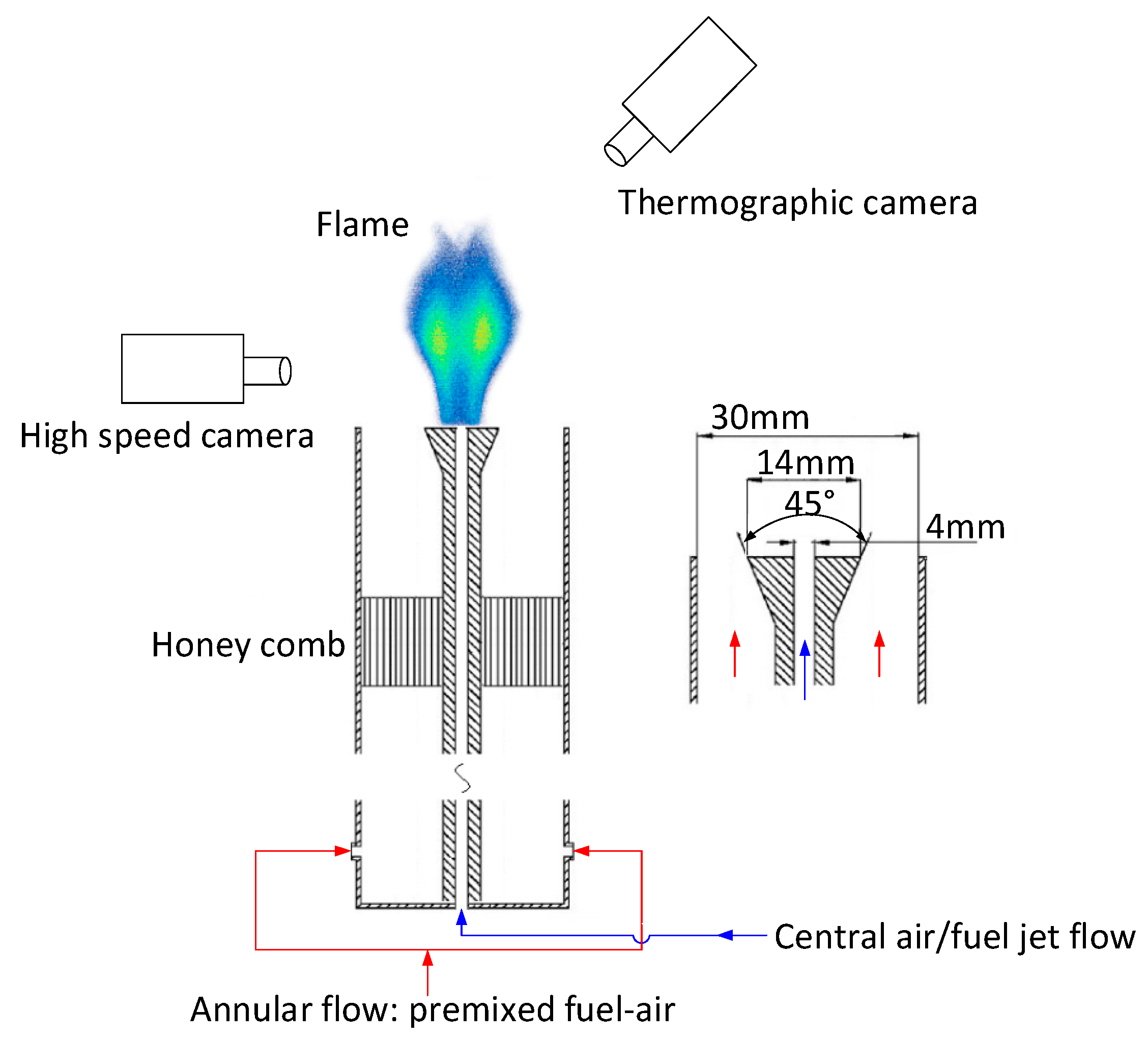
2.1. Experimental Apparatus

As shown schematically in Figure 2, the burner having an annular channel together with a 45° conical-shape bluff-body mounted in its center was employed. The annular channel had an inner diameter of da = 30 mm, while the removable bluff-body having an outer diameter of db = 14 mm and its inner diameter being dj = 4 mm. Fuel (methane) and air was premixed and injected through the annular channel and pure air or fuel flow was fed into the central pipe. About 200 mm upstream of the bluff-body, a ceramic honeycomb was mounted in order to generate a uniform annular flow and to avoid flame flashing back into a further upstream region.
The mass flow rates of the central air/fuel flow together with the fuel flow in the annular flow were controlled by three Bronkhorst mass flow controllers (MFC). An Alicat (MCR 150) MFC controlled the mass flow rate of the annular air flow. The Bronkhorst MFC was calibrated at 300K with an uncertainty of 1%. On the basis of the exit geometry of the burner, the bulk velocity of the premixed annular flow was in the range of 1.85 to 2.77 m/s, while the equivalence ratio being set to between Φ = 0.64 to lean blowout limits. When Φ = 0.64, a stable flame could be obtained. The velocity of the central air jet varied between Ua = 0 and 29 m/s, while the central fuel velocity ranging from Uf = 0 to 1.33 m/s. All experiments were carried out without confinement under atmospheric conditions with the temperature kept constant at 297 ± 3K.

2.2. High-Speed Photography
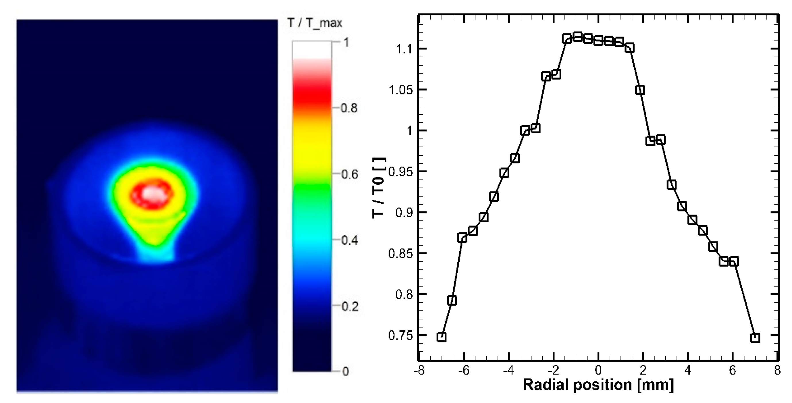
A high-speed photography technique and a thermographic camera were adopted for studying the flame behaviors and the temperature on the upper surface of the bluff-body, respectively. A high-speed CMOS camera (Vision Research Phantom V611) with a resolution of 800 × 1280 pixels and depth of 12 bit was utilized to record the broadband chemiluminescence of the flame. Since the chemiluminescence intensity varied with the equivalence ratio of the annular flow and with the heat release rate from the flame [29,30], the frame recording rate altered according to the signal intensity. During the experiments, the recording rate was set between 200fps to 800fps to study the dynamics of the flame. The low recording rate ensured a long exposure time (Texposure = 1/frecording rate) for obtaining more chemiluminescence signal from for each frame of the flame. Digital image process was fulfilled based on the DaVis (v.8.1.4) software and the in-house developed Matlab code. Time-averaged (within the recording time duration of 2 s) and root mean square (RMS) of the broadband chemiluminescence from the flame were used to study the flame structures and its instabilities.

2.3. Thermography

An infrared thermographic camera (Testo 881-3) was utilized to visualize the temperature distribution on the upper surface of the bluff-body. The burner was un-confined ensuring the measuring of the temperature on the upper surface of the bluff-body practically and trustable. The place of the thermographic camera was shown in Figure 2. The angle between the burner axis and the thermographic camera’s focus plane was approximately 45°. Under ideal conditions, the camera should be placed at the central axis of the burner downstream of the flame, focusing on the bluff-body, or at a 0° to the burner axis. The heat from the combustion, as a consequence, would then damage the camera. Thus, the camera was set at a proper degree from the burner axis downstream of the flame. The thermographic camera had a spatial resolution of 320 × 240 pixels.
Figure 3 shows the typical infrared image of the surface of the bluff-body and its temperature distribution at the symmetric plane along the radial direction. As reported by Euler et al. [25], the temperature peaked in the center of the bluff-body. However, here the high temperature in the central region at –2 mm < r < 2 mm was probably caused by infrared lights reflected from the inner wall of the central fuel injection pipe. Thus, in the study, temperature data in the center injection pipe was deleted in the analysis process. The temperature on the inner edge of the bluff-body was treated as the representative temperature Tedge. The emissivity (ε) of the bluff-body (stainless steel type 301) is found to be varied from 0.54 to 0.63. In the base case without any central jet, setting the emissivity ε = 0.58, the annular flow equivalence ratio Φ = 0.64, Uc = 2.77 m/s and Uj = 0 m/s, the temperature Tedge was approximately 480 K, which was referred to as T0 as the base case in the present study. The ratios of Tedge in different cases to T0 in the base case were used to obtain the cooling effects caused by the injection of a central jet with a minimized error due to the selection of the material emissivity. The error of that temperature ratio, when changing the emissivity from 0.54 to 0.63, was within 2%. Figure 3 shows the ratio of T/T0 along the radius direction on the upper surface of the bluff-body in the base case.
To maintain a thermodynamic equilibrium condition of the bluff-body, the flame was held stable for at least 5 mins, with the maximum temperature being showed in the thermographic camera stayed stable for at least 2 mins. Then, the fuel supply was shut down and the variance of Tedge was recorded, as shown in Figure 4. The flame could radiate infrared light which would strongly affect the thermographic results. Thus, the temperature on the surface of the bluff-body was recorded continually since the flame was ongoing until the flame quenched completely, with a recording rate for the thermographic camera at f = 2 Hz. A typical temperature variance of Tedge during that procedure was shown in Figure 4. When the flame was ongoing, Tedge remained stable, indicating a stable flame and a thermodynamic equilibrium condition on the surface of the bluff-body. At the same time, when the flame was ongoing, it could be found that Tedge was higher due to the infrared light from the flame. Afterwards, when fuel supply was shut down, Tedge dropped considerably. The temperature gradient was sharp initially since a weak flame, which was caused by combustion of the fuel in the supply system downstream of the MFC, remained attached to the bluff-body. When the flame vanished completely, the temperature on the surface of the bluff-body decreased slowly, due to the heat convection from the bluff-body to the environment. As shown in Figure 4, the time when the flame quenched completely was set as the time t = 0 s. After that, the temperature decreased at a rate of less than 4 K/s, which was much lower than that during the fuel shut down procedure. Thus, the representative temperature of the bluff-body Tedge was selected at t < 1 s after the annular flame disappeared completely. The corresponding error due to the temperature recording time selection was within 2%.

3. Results and Discussions

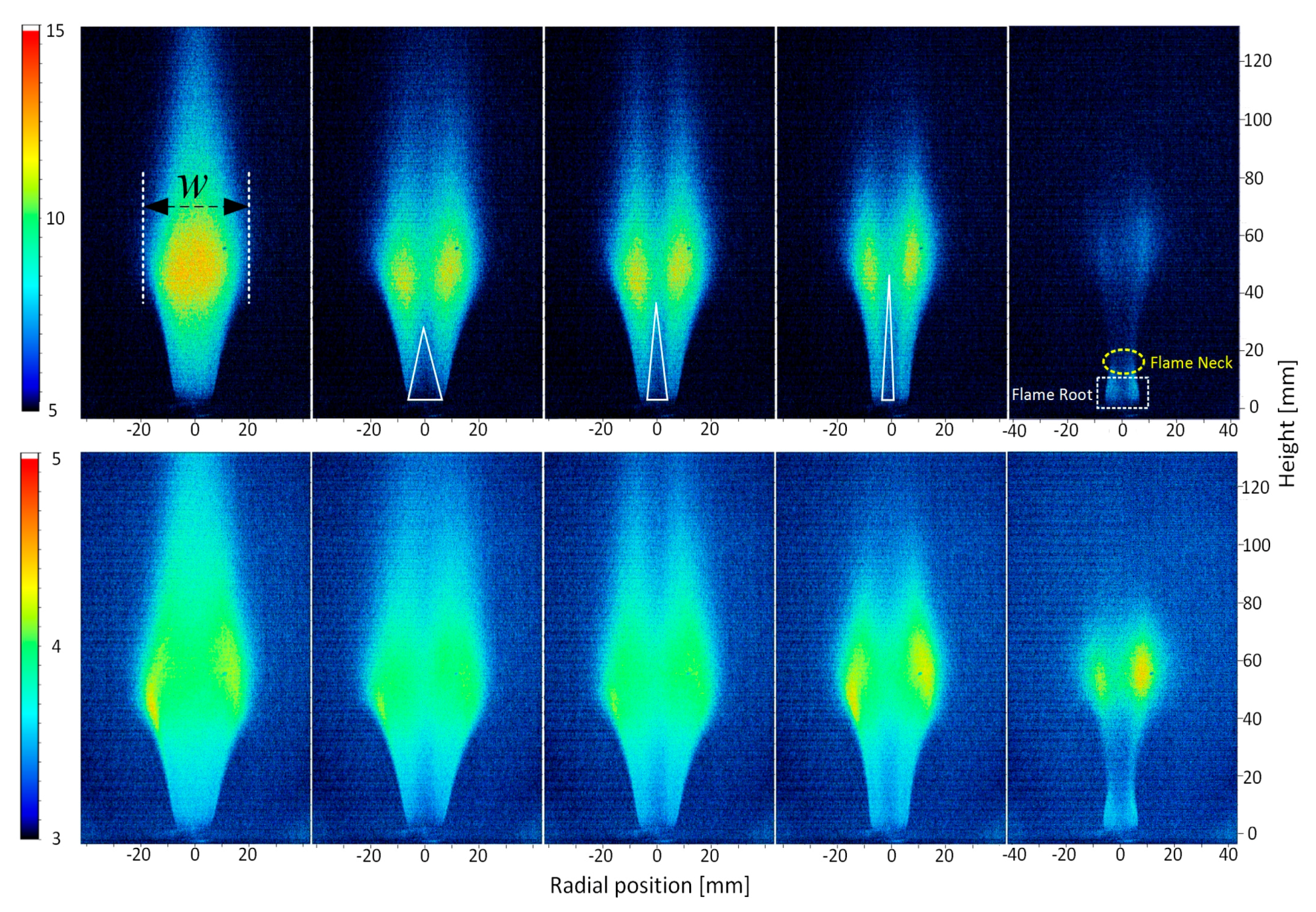
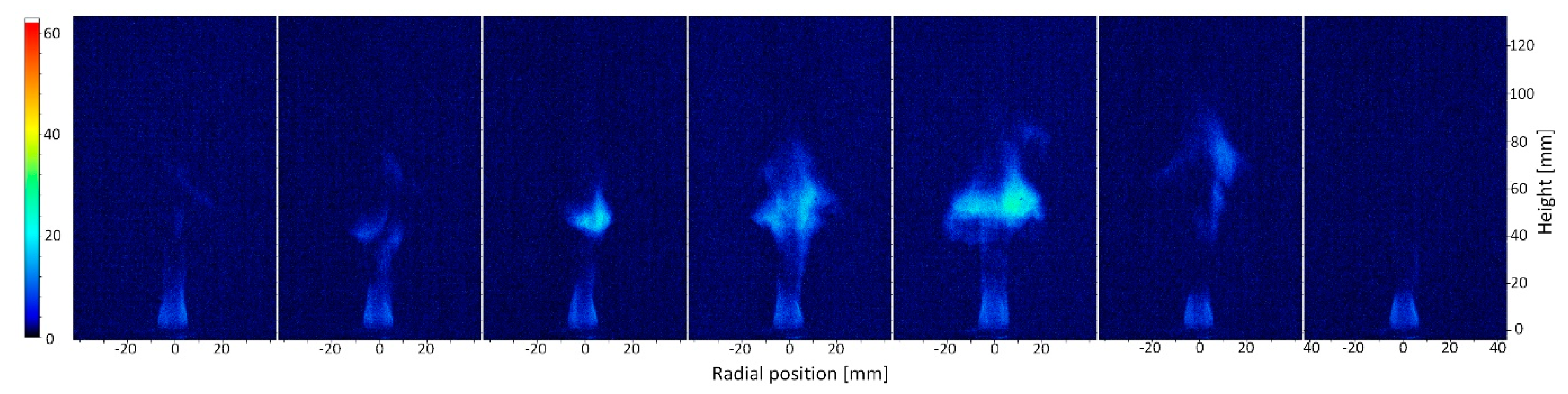
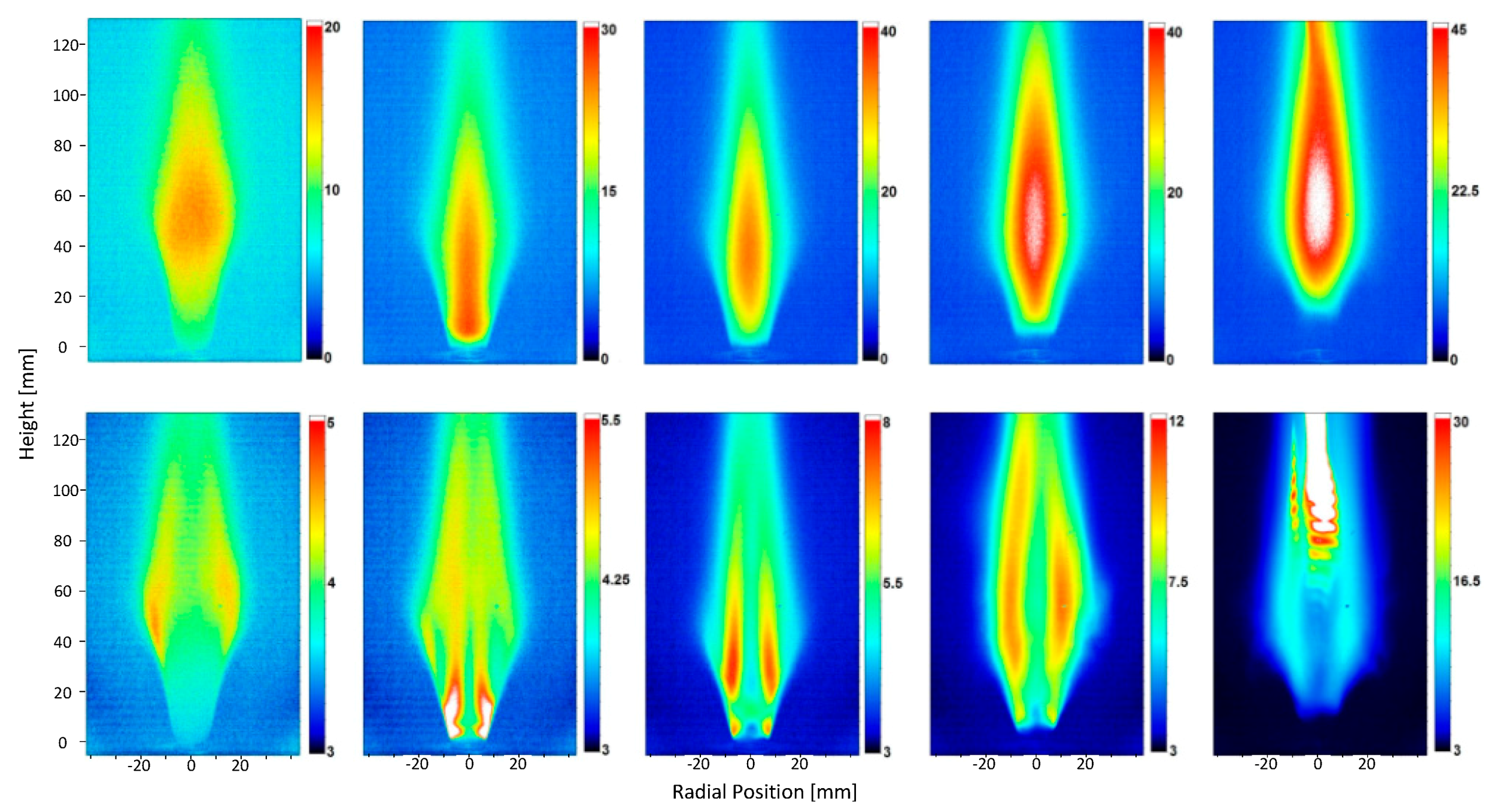
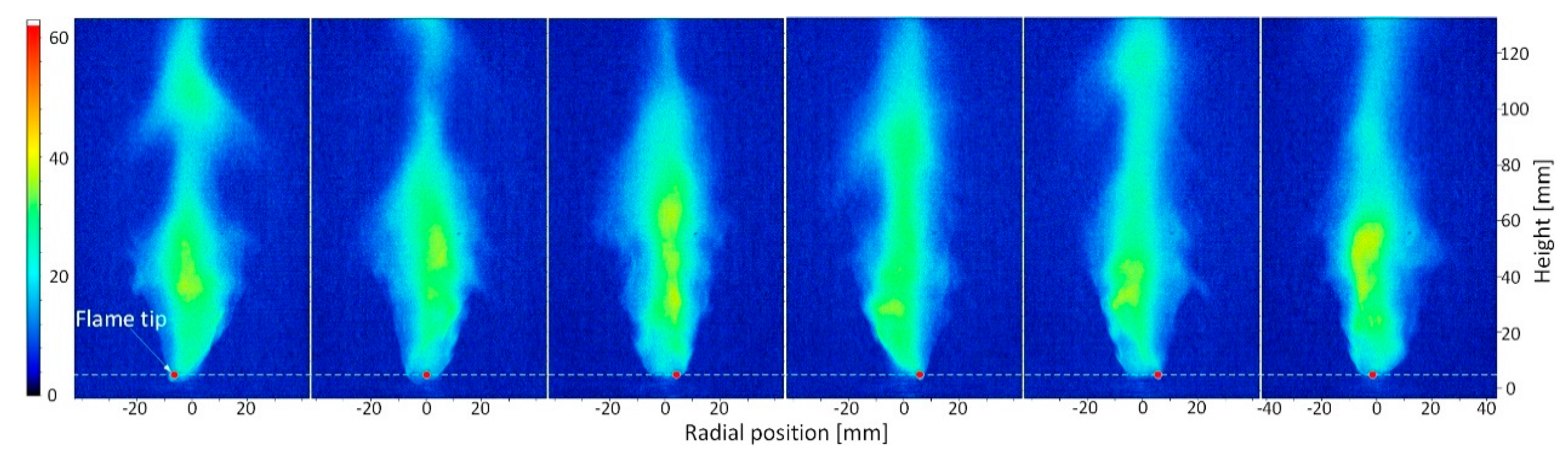
3.1. Flame Structures

With a central air/fuel jet, structures of the flame changed significantly. The time-averaged flame structures and the flame dynamics in case with a central air jet are shown in Figure 5, when holding the frame recording rates at 500 fps. It shows the flame structures under conditions of Uc = 1.85 m/s and Φ = 0.64.
Figure 5 shows that without a central air jet, the heat release zone of the flame peaks on the central axis behind the bluff-body. However, with a central air jet, the heat release zone got apart from the burner axis. When the velocity of the central air jet was low (Ua/Uc = 0.79), the flame width (w, as shown in Figure 5) became broader than that in case without a central air jet. One can note in Figure 1 that, when the flow fields were dominated by the annular flow, the central air jet formed an inner vortex (with an extremely fuel-lean condition) to avoid the flame being attached to the bluff-body. The fresh air inner vortex zone is shown schematically by the white triangle in Figure 5. When the flow fields were dominated by the annular flow, the flame front was found to be attached to the outer edge of the bluff-body, meanwhile the central air penetrated short downstream of the flame holder. That inner vortex layer, which was formed by the fresh and cold air jet through the central pipe, could also reduce the heat convection from the combustion products to the upper surface of the bluff-body. As will be discussed later, it might be the reason for the decrease in the temperature on the surface of the bluff-body.
An increase in the velocity of the central air jet shortened the annular premixed flame; meanwhile the flame width became narrower. The flame was weakened and the size of the heat release zone shrank, with the increase in the velocity of the central air jet. It was caused by the overall reduction in the equivalence ratio in the main flame, with a central air injection. At the same time, with the increase in the mass flow rate of the central air jet, the area of the flame front attached to the surface of the bluff-body became enlarged. The air jet penetrated higher into the main flame zone. The same as shown in Figure 1 and in the literature [19], the flow fields might turn into neither jet dominating, then finally to central jet dominating. Further research about the flow structures and their effects on the bluff-body stabilized flame behaviors will be presented in our future study.
The unstable flame behavior for case in which Ua/Uc = 13.22 is shown in Figure 6. The frame recording rate was set to be lower here (200 fps) due to the weaker light intensity from the flame under globally lean conditions. The interval time between two adjacent images shown in Figure 6 is 25 ms. As shown in Figure 6, the flame neck (where the flame width was narrower than the diameter of the bluff-body) showed up when Ua was high (Ua/Uc = 13.22). When Ua increased to a critical value, the premixed annular flame might be interrupted by the high strain rate at the flame neck region. With a further increase in Ua, flame in the far downstream region extinguished. Whereas, only the flame root which was attached to the bluff-body was maintained. As shown in Figure 6, the flame downstream of the flame neck region extinct and later re-ignited by the stable flame root. Thus, the flame was found to be flashing downstream of the flame neck together with a strong noise sound. The high strain rate (which might be the dominant factor according to Shanbhogue et al. [11]), strong shear stress and the locally lean condition were proposed as the reasons for the flame quenching downstream of the flame neck region. The flame root attaching to the bluff-body, supplied the heat and radical sources to re-ignite the fresh fuel-air mixture downstream which was originated from the annular flow. The flame root was probably stabilized by the recirculation zone of the bluff-body. The behavior of the flame root was not strongly affected by the downstream flame conditions. To be more specific, the flame root could always be stabilized regardless whether the flashing flame downstream was ongoing or being quenched. In addition, in the RMS images in Figure 5, it is noted that the heat fluctuation peaked in the annular flow shear layer under conditions with/without a central air injection. In the region near the bluff-body (h < 20 mm), the flames in all cases were stable. In the region h = 60 mm, the split-flashing flame had the stronger heat fluctuation than that in any other cases. The flame in case with Ua/Uc = 13.22 had high RMS value (but low chemiluminescence intensity value in the time-averaged image) in the region h = 60 mm, indicating the unstable flame tip flashing downstream of the flame neck region.
The injection of a central fuel jet also has strong effects on the flame dynamics and on its time-averaged structures. As shown in Figure 7, with the injection of a central fuel jet, the flame gets detached from the bluff-body. The local fuel-rich condition in the inner vortex caused the flame lifting off from the surface of the bluff-body. The liftoff height increased with the increase in the velocity of the central fuel jet. Since more heat was released with the injection of the central jet fuel, the color scales of the time-averaged flame images in Figure 7 alter with one another. In addition, it was observed that with the increase in the mass flow rate of the central fuel jet, more soot could be formed, thus changing the color of the lean premixed methane-air flame from bluish to yellowish. The yellowish flame behaved more like a diffusion jet flame, with the annular flow acting as the oxidant. Differed from the effects of a central air jet, the central fuel injection remained the peak heat release zone location in the central axis downstream of the bluff-body. The heat release fluctuation peaked in the flame root region (h < 20 mm) under the conditions with a small amount of central fuel injection (Uf/Uc < 0.089). With the increase in the mass flow rate of the central fuel jet, the heat release fluctuation peaked into the jet shear layer.
With the injection of a central fuel jet, another interesting unstable flame behavior was observed, as shown in Figure 8 with the frame recording rate at 800 fps. When a small amount of the central fuel jet (Uf/Uc = 0.045) was injected into the flow field, the flame turned to be unstable, with the flame tip attached to the bluff-body’s outer edge. The attaching point of the flame tip moved circularly along the bluff-body outer edge. This unstable flame behavior was dominated by the central fuel jet, because a change in the equivalence ratio of the annular flow did not significantly alter the flame instability features. The radial position of the unsteady flame tip is shown in Figure 9. A fast Fourier transform (FFT) code in Matlab was used to analyze the oscillations of the flame tip. In Figure 9, one can note that the flame tip alters its position around the axis of the bluff-body at −7 mm < r < 7 mm, indicating the flame tip was attached to the outer edge of the bluff-body. The unstable behavior of the flame tip might be caused by the unstable variance of the local equivalence ratio together with the unstable heat transfer from the flame to the bluff-body. When the flame tip was attached to one point in the outer edge of the bluff-body, more heat was then convected to the bluff-body through that point, thus the local temperature was lowered which might lead to local extinction of the flame. At the same time, the unstable wakes shedding from the bluff-body might also contribute to the instable behavior of the flame tip. The interaction of the wakes with the flame changed the local flow velocity and the local equivalence ratio, which could also result in the flame tip moving along the outer edge of the bluff-body. Another reason might be the effects of gravity in the situation in which a fluid is stratified vertically. The buoyancy force would then destabilize the flame if the direction of the flow is such as to place the low-density combustion products below the high density un-burnt mixtures [31]. The central fuel jet has a lower density than that of the fuel–air mixture in the annular flow which would lead to the buoyancy-driven instabilities.
As shown in Figure 10, the dominate frequency of the oscillation for the flame tip is approximately 20 Hz for case with annular mixture equivalence ratio of Φ = 0.64, the bulk velocity of Uc = 2.77 m/s and Uf/Uc = 0.045. An increase in the mass flow rate of the central fuel jet led to a decrease in the dominant frequency. As shown in Figure 7, the increase in the mass flow rate of the central fuel jet also resulted in an increase of the flame liftoff height, which probably is one of the reasons for the variance of the dominate frequency of the oscillation of the flame tip. When the central fuel flow rate exceeded a critical value, the flame overall acted much more like a diffusion jet flame rather than a bluff-body stabilized premixed flame. As part of future work, a deeper insight in using PIV, Planar Laser Induced Fluorescence (PLIF) and numerical simulations concerning the local equivalence ratio, the heat transfer and the corresponding flow structures will be sought after.

3.2. Blowout Limits

Flame blowout limit is important in evaluating the performance of a flame holder. The blowout limit is the equivalence ratio of the premixed reactants in annular flow at which the flame became visualized absence. The flame blowout limits were captured by reductions in the mass flow rate of the annular fuel flow from a stable flame (i.e., Φ = 0.64) until the flame being vanished. In that process, the mass flow rate of fuel was reduced at a step of 0.04 standard liter per minute, while the mass flow rates of other flows, such as the annular air flow and the central air jet flow, being kept constant. After each step of reducing the annular fuel flow rate, all the flow conditions were kept constant for at least 2 min to achieve a thermal equilibrium before the next fuel-reduction step. The blowout of the annular premixed flame could not be observed with a central fuel injection. This was due to the fact that when the equivalence ratio of the annular flow was reduced to the minimum level, Φ = 0, (pure air in the annular flow), with a central fuel jet, the flame could also be maintained in terms of a bluff-body stabilized diffusion flame. Hence, in the paper only the effects of the central air injection on the flame blowout limits were studied, as shown in Figure 11.
It can be found in Figure 11 that with a central air jet, the flame blowout limits increase as a whole. The increase in flame blowout limits was caused by the changing of flow structures behind the bluff-body. As shown in Figure 1, when the velocity of the central jet was low, the annular flow dominated the flow structures. Then a fresh air layer was formed, as shown in Figure 5. At the same time, a small area of the flame front was attached to the bluff-body. Thus, the flame was extremely unstable and readily to have a blowout. With a further increase in Ua, the flame blowout limits decreased, which might be due to the alternation of the flow structures, from annular flow dominating to neither jet dominating condition, as shown in Figure 1 and Figure 5. The central air jet penetrated more and effects from the central air jet on the near field of the surface of the bluff-body gets weaker. A larger area of the flame front got attached to the surface of the bluff-body, while the flame became somewhat more stable. With a further increase in the velocity of the central air jet, the flame blowout limits increased. It is worth noting here that two different blowout phenomena occurred during the experiments. When Ua/Uc < 5.5, the flame blowout occurred suddenly without the split-flashing flame mode. The entire flame vanished suddenly with a small reduction in the mass flow rate of the annular fuel flow. The flame front that was found to be attached to the bluff-body could not be sustained anymore. When Ua/Uc > 5.5, however, with a reduction in the equivalence ratio of the annular flow, the split-flashing flame (shown in Figure 6) took place before the occurrence of the flame blowout. A further decrease in the mass flow rate of the annular fuel flow quenched the flashing flame downstream of the blue-body firstly, with only the flame root being stabilized. A little further reduction in the mass flow rate of the annular fuel flow finally quenched the flame root. As discussed above, the occurrence of the flame neck was resulted from the penetration of the central air jet. The local flame quenching and re-ignition were supposed to be reasoned by the local high strain rate and the locally fuel-lean condition at the neck region. As shown in Figure 11, when Ua was high (Ua/Uc > 10), higher blowout limits were observed. It might be caused by the enhanced heat convection from the bluff-body to the central jet.

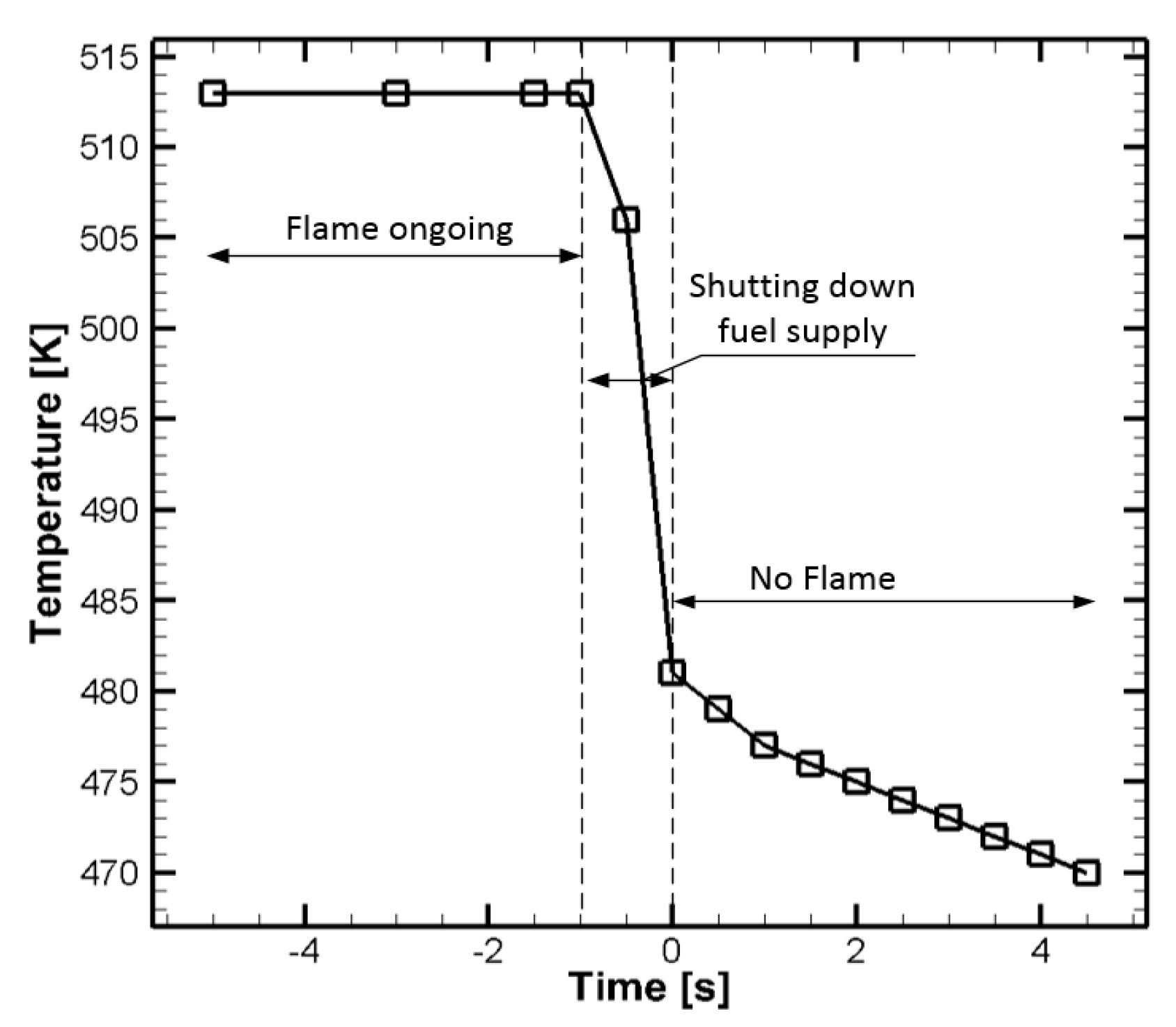
3.3. Bluff-Body Upper Surface Temperature

In this section, results of the temperature on the upper surface of the bluff-body are presented and discussed. Experiments reported here were performed holding the velocity of the premixed annular flow at Uc = 2.77 m/s and the equivalence ratio at Φ = 0.64. Effects of the central air and fuel injections were studied on the basis of experiments with Ua/Uc = 0–7.8 and Uf/Uc = 0–0.36, respectively. The temperature Tedge varied with the injection of a central air/fuel jet, as shown in Figure 12.
When the velocity of a central air injection was low (Ua/Uc ≈ 1), the temperature on the surface of the bluff-body dropped to less than 80% of T0, as shown in Figure 12. For the case in which Ua/Uc ≈ 1, the temperature of the bluff-body was lower than in any other case with a central air jet. That lower temperature was probably produced by the local flow structures downstream of the bluff-body. When Ua/Uc ≈ 1, the flow fields behind the bluff-body were believed to be dominated by the annular channel flow, the same as that shown in Figure 1. A fresh air layer was then formed near the upper surface of the bluff-body. It then could prevent the heat convection from the combustion products to the bluff-body. Afterwards, an increase in the velocity of the central air jet increased the temperature ratio up to approximately 87%. With an increase in the velocity of the central jet flow, the air jet penetrated higher with weakened heat convection from the bluff-body to the central jet. Thus, as shown in Figure 12 (left), when the flow field was central jet dominating, an increase in the velocity of the central air jet did not significantly change the heat load to the surface of the bluff-body, even when the flame was increasingly weakened by the central air injection.
With the injection of a central fuel jet, Tedge decreased significantly, till even less than 75% of T0. The main reason for that lower temperature was the occurrence of flame lifting off from the bluff-body, with the injection of a central fuel jet. As described previously, with a central fuel jet, the time-averaged flame structure appeared a detached pattern from the bluff-body. At the same time, the transient flame structures showed increased flame instabilities. The flame liftoff height increased with the increase in the mass flow rate of the central fuel jet, until flame blowout occurred. Thus, the heat load to the surface of the bluff-body was reduced correspondingly at the same time.
Taking the temperature on the surface of the bluff-body into consideration, a central air jet and a central fuel jet are practical methods to reduce the heat load to the bluff-body in bluff-body stabilized premixed flames. However, the disadvantage with a central air injection is that the flame then becomes more unstable and easier to blowout. A central fuel injection, which acts like a pilot in stabilizing the premixed annular flame, caused a reduction of the heat load to the upper surface of the bluff-body.

4. Conclusions

The effects of a central air/fuel jet on the bluff-body stabilized premixed methane-air flames were studied in the present paper. The temperature on the upper surface of the bluff-body was obtained by a thermographic camera and the flame structures were captured using a high-speed CMOS camera. The conclusions could be made as follows:
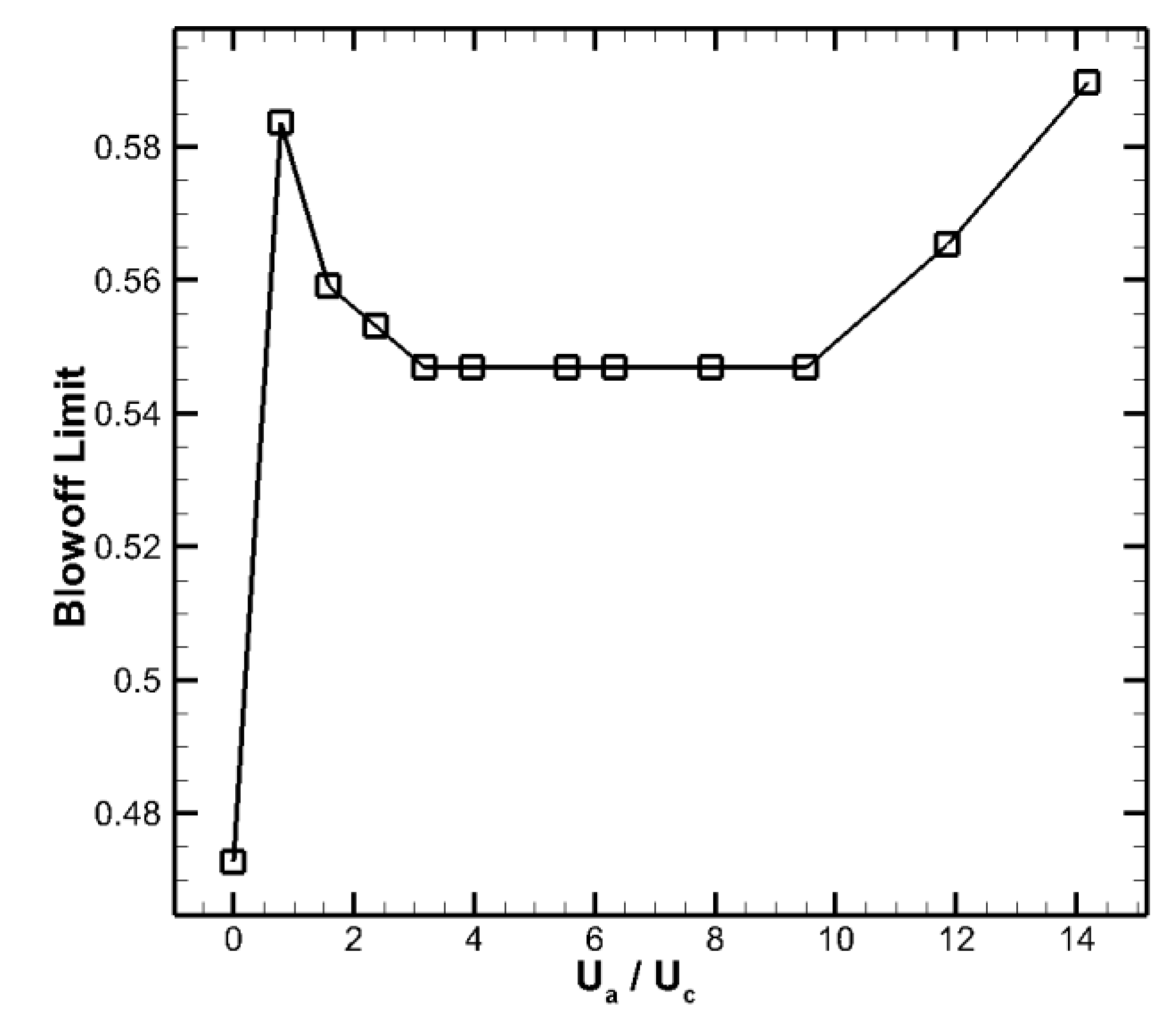
  • A central air jet makes the premixed annular flame more unstable leading to an easier blowout of the annular flame.
  • Two different flame blowout phenomena: With/without the occurrence of split-flashing flame mode, was observed with a central air jet injection.
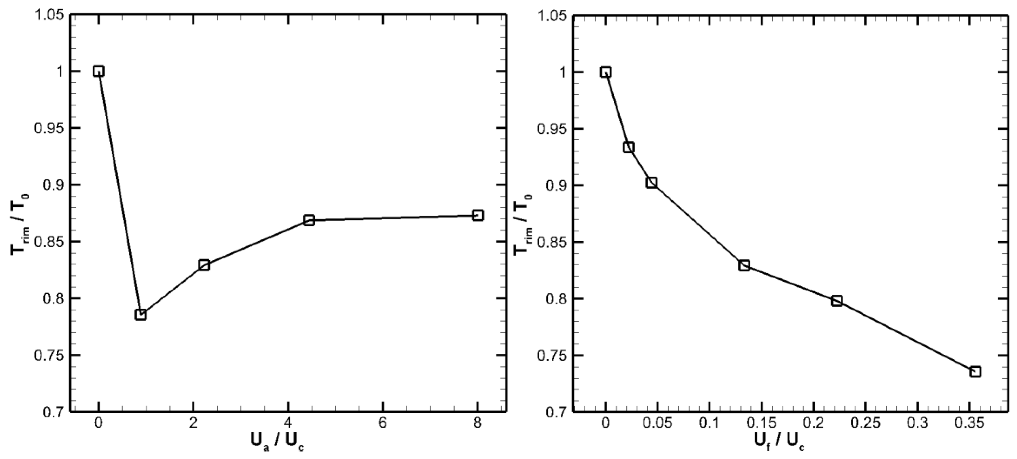
  • With a central air/fuel jet, the temperature on the upper surface of the bluff-body was reduced noticeably.
  • The reduction in the temperature on the surface of the bluff-body with a central fuel injection is found to be caused by the flame lifting off from the bluff-body. The liftoff height increases with the increase in the mass flow rate of the central fuel flow, while the temperature of the bluff-body being decreased correspondingly.
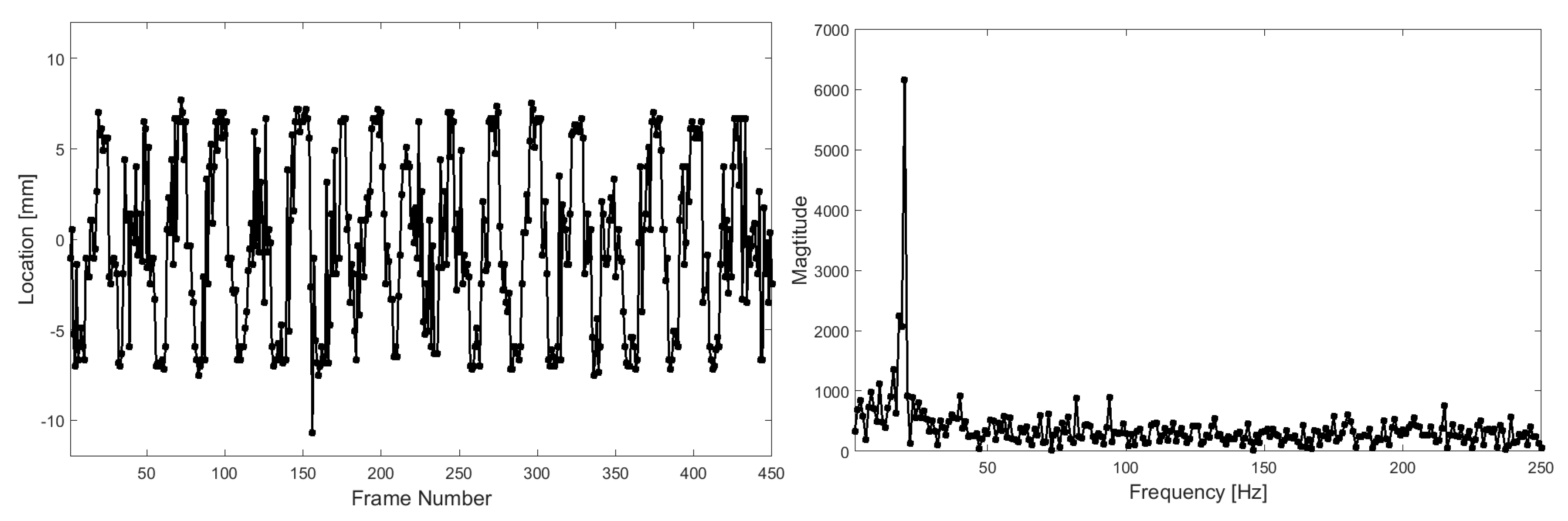
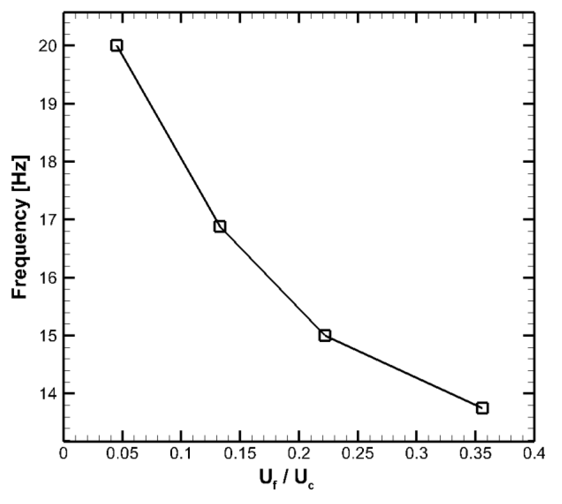
  • Under conditions with a central fuel jet, the annular premixed flame was found unsteadily attached at the outer edge of the bluff-body. That attached point had a circular motion along the outer edge of the bluff-body. The dominant frequency of the oscillation of the flame tip decreased with an increase in the velocity of the central fuel jet.
Further detailed investigations of the flow structures as well as the interactions of a central jet with the annular flame are required.

Acknowledgments

The work was financially supported by the Swedish Energy Agency, the Swedish Research Council (VR) and the European Research Council (Advanced Grant TUCLA program). Yiheng Tong, Shuang Chen and Mao Li would like to thank the financial support from the China Scholarship Council (CSC).

Author Contributions

Yiheng Tong designed the experiments, conducted the data analysis and wrote the paper; Shuang Chen and Zhongshan Li took part in the burner design; Mao Li took part in the experimental work; Zhongshan Li and Jens Klingmann proofread the paper.

Conflicts of Interest

The authors declare no conflicts of interest.

References

  1. Chaudhuri, S.; Cetegen, B.M. Blowoff characteristics of bluff-body stabilized conical premixed flames with upstream spatial mixture gradients and velocity oscillations. Combust. Flame 2008, 153, 616–633. [Google Scholar] [CrossRef]
  2. Guo, P.; Zang, S.; Ge, B. Technical brief: Predictions of flow field for circular-disk bluff-body stabilized flame investigated by large eddy simulation and experiments. J. Eng. Gas Turbines Power 2010, 132, 054503. [Google Scholar] [CrossRef]
  3. Zukoski, E.E.; Marble, F.E. The role of wake transition in the process of flame stabilization on bluff bodies. In AGARD Combustion Researches and Reviews; Butterworths: London, UK, 1955. [Google Scholar]
  4. Zuikoski, E.; Marble, F. Gas Dynamic Symposium on Aerothermochemistry; Northwestern University Press: Evanston, IL, USA, 1955. [Google Scholar]
  5. Longwell, J. Flame Stabilization by Bluff Bodies and Turbulent Flames in Ducts. Symp. (Int.) Combust. 1953, 4, 90–97. [Google Scholar] [CrossRef]
  6. Longwell, J.P.; Frost, E.E.; Weiss, M.A. Flame stability in bluff body recirculation zones. Ind. Eng. Chem. 1953, 45, 1629–1633. [Google Scholar] [CrossRef]
  7. Wright, F. Bluff-body flame stabilization: Blockage effects. Combust. Flame 1959, 3, 319–337. [Google Scholar] [CrossRef]
  8. Pan, J.; Vangsness, M.; Ballal, D. Aerodynamics of Bluff Body Stabilized Confined Turbulent Premixed Flames. J. Eng. Gas Turbines Power 1992, 114, 783–789. [Google Scholar] [CrossRef]
  9. Lefebvre, A.H.; Ballal, D.R. Gas Turbine Combustion; CRC Press: Boca Raton, FL, USA, 2010. [Google Scholar]
  10. Barrere, M.; Mestre, A. Selected Combustion Problems; Stabilisation des Flammes par des Obstacles; Butterworth Scientific Publications: London, UK, 1954. [Google Scholar]
  11. Shanbhogue, S.J.; Husain, S.; Lieuwen, T. Lean blowoff of bluff body stabilized flames: Scaling and dynamics. Prog. Energy Combust. Sci. 2009, 35, 98–120. [Google Scholar] [CrossRef]
  12. Chaparro, A.A.; Cetegen, B.M. Blowoff characteristics of bluff-body stabilized conical premixed flames under upstream velocity modulation. Combust. Flame 2006, 144, 318–335. [Google Scholar] [CrossRef]
  13. Chaudhuri, S.; Cetegen, B.M. Blowoff characteristics of bluff-body stabilized conical premixed flames in a duct with upstream spatial mixture gradients and velocity oscillations. Combust. Sci. Technol. 2009, 181, 555–569. [Google Scholar] [CrossRef]
  14. Chaudhuri, S.; Kostka, S.; Renfro, M.W.; Cetegen, B.M. Blowoff dynamics of bluff body stabilized turbulent premixed flames. Combust. Flame 2010, 157, 790–802. [Google Scholar] [CrossRef]
  15. Wan, J.; Fan, A.; Maruta, K.; Yao, H.; Liu, W. Experimental and numerical investigation on combustion characteristics of premixed hydrogen/air flame in a micro-combustor with a bluff body. Int. J. Hydrogen Energy 2012, 37, 19190–19197. [Google Scholar] [CrossRef]
  16. Fan, A.; Wan, J.; Liu, Y.; Pi, B.; Yao, H.; Liu, W. Effect of bluff body shape on the blow-off limit of hydrogen/air flame in a planar micro-combustor. Appl. Therm. Eng. 2014, 62, 13–19. [Google Scholar] [CrossRef]
  17. Bagheri, G.; Hosseini, S.E.; Wahid, M.A. Effects of bluff body shape on the flame stability in premixed micro-combustion of hydrogen–air mixture. Appl. Therm. Eng. 2014, 67, 266–272. [Google Scholar] [CrossRef]
  18. Fan, A.; Wan, J.; Maruta, K.; Yao, H.; Liu, W. Interactions between heat transfer, flow field and flame stabilization in a micro-combustor with a bluff body. Int. J. Heat Mass Transf. 2013, 66, 72–79. [Google Scholar] [CrossRef]
  19. Roquemore, W.; Tankin, R.; Chiu, H.; Lottes, S. A study of a bluff-body combustor using laser sheet lighting. Exp. Fluids 1986, 4, 205–213. [Google Scholar] [CrossRef]
  20. Caetano, N.R.; da Silva, L.F.F. A comparative experimental study of turbulent non premixed flames stabilized by a bluff-body burner. Exp. Therm. Fluid Sci. 2015, 63, 20–33. [Google Scholar] [CrossRef]
  21. Esquiva-Dano, I.; Nguyen, H.; Escudie, D. Influence of a bluff-body’s shape on the stabilization regime of non-premixed flames. Combust. Flame 2001, 127, 2167–2180. [Google Scholar] [CrossRef]
  22. Schefer, R.; Namazian, M.; Kelly, J.; Perrin, M. Effect of confinement on bluff-body burner recirculation zone characteristics and flame stability. Combust. Sci. Technol. 1996, 120, 185–211. [Google Scholar] [CrossRef]
  23. Tang, H.; Yang, D.; Zhang, T.; Zhu, M. Characteristics of flame modes for a conical bluff body burner with a central fuel jet. J. Eng. Gas Turbines Power 2013, 135, 091507. [Google Scholar] [CrossRef]
  24. Nishimura, T.; Kaga, T.; Shirotani, K.; Kadowaki, J. Vortex structures and temperature fluctuations in a bluff-body burner. J. Vis. 1998, 1, 271–281. [Google Scholar] [CrossRef]
  25. Euler, M.; Zhou, R.; Hochgreb, S.; Dreizler, A. Temperature measurements of the bluff body surface of a swirl burner using phosphor thermometry. Combust. Flame 2014, 161, 2842–2848. [Google Scholar] [CrossRef]
  26. Euler, M.; Zhou, R.; Hochgreb, S.; Dreizler, A. Temperature Measurements of the Bluff Body Surface of Cambridge Stratified Swirl Burner Using Phosphor Thermometry. In Proceedings of the European Combustion Meeting, Lund, Sweden, 25–28 June 2013; p. 33. [Google Scholar]
  27. Russi, M.; Cornet, I.; Cornog, R. The influence of flame holder temperature on flame stabilization. In Symposium (International) on Combustion; Elsevier: Amsterdam, The Netherlands, 1953; pp. 743–748. [Google Scholar]
  28. Lin, C.-X.; Holder, R.J. Reacting turbulent flow and thermal field in a channel with inclined bluff body flame holders. J. Heat Transf. 2010, 132, 091203. [Google Scholar] [CrossRef]
  29. Li, M.; Tong, Y.; Klingmann, J.; Thern, M. Impact of vitiation on a swirl-stabilized and premixed methane flame. Energies 2017, 10, 1557. [Google Scholar] [CrossRef]
  30. Tong, Y.; Li, M.; Thern, M.; Klingmann, J. An experimental study of effects of confinement ratio on swirl stabilized flame macrostructures. In Proceedings of the ASME 2017 Power Conference Joint With ICOPE-17 Collocated with the ASME 2017 11th International Conference on Energy Sustainability, the ASME 2017 15th International Conference on Fuel Cell Science, Engineering and Technology, and the ASME 2017 Nuclear Forum, Charlotte, NC, USA, 26–30 June 2017; American Society of Mechanical Engineers: New York, NY, USA, 2017; p. V001T004A007. [Google Scholar]
  31. Coats, C. Coherent structures in combustion. Prog. Energy Combust. Sci. 1996, 22, 427–509. [Google Scholar] [CrossRef]
Figure 1. A schematic of time-averaged flow fields downstream of a bluff-body with a central jet (reproduced from [19]).
Energies 10 02011 g001
Figure 2. A schematic of the experimental setup and the burner.
Energies 10 02011 g002
Figure 3. Typical infrared image (left) and temperature ratio along the radius direction (right).
Energies 10 02011 g003
Figure 4. Typical temperature changes of Tedge during shutting down the fuel supply.
Energies 10 02011 g004
Figure 5. Time-averaged (upper row) and root mean square (RMS) (lower row) images of the flame structures with a central air jet (from left to right: Ua/Uc = 0, 0.79, 3.94, 7.87 and 13.22).
Energies 10 02011 g005
Figure 6. Flame instability near blowout due to a central air jet injection.
Energies 10 02011 g006
Figure 7. The time-averaged (upper row) and RMS (lower row) images of different flame structures with a central fuel injection (from left to right: Uf/Uc = 0, 0.045, 0.089, 0.22 and 0.36).
Energies 10 02011 g007
Figure 8. Typical flame instable behavior caused by a central fuel jet injection (the flame tip is moving circularly along the outer edge of the bluff-body).
Energies 10 02011 g008
Figure 9. Radial position of flame tip (left) and its FFT results (right).
Energies 10 02011 g009
Figure 10. Effects of a central fuel jet on flame tip instability.
Energies 10 02011 g010
Figure 11. Effects of a central air jet on the flame blowout limits.
Energies 10 02011 g011
Figure 12. Effects of central air (left) and fuel (right) jet on the temperature of bluff-body surface
Energies 10 02011 g012

