1. Introduction
Dryers that commonly employ hot air to promptly remove moisture content at high operating temperature are widespread and used in many industrial processes. In general, the air has to be heated at the traditional dryer inlet in order to increase the temperature and reduce the relative humidity of air, so that the water contained in the substance can be more easily vaporized because of the large gradient of water concentration between the hot air and the substance. The heating of inflow air for drying consumes a lot of energy, especially when drying in humid regions.
Reducing the relative humidity of air at the inlet using desiccant is one of the effective ways to reduce the energy consumption while drying. Zouaoui et al. [
1] mentioned that dehumidification by adsorption is a physical process resulting from the pressure difference of water vapor between the desiccant surface and the surrounding air. Silica gel is one of the common adsorbents because of its numerous advantages such as larger pores, larger surface area, and excellent dehumidification capability [
1]. In fact, desiccant devices using silica gel as an absorbent have been widely used for dehumidification in many industrial areas [
2] in addition to its use in air conditioning systems coupling with a heat source [
3,
4,
5].
In 1932, Miller [
6] proposed a patent that claimed an adsorption system using silica gel as an absorbent. Ahlberg [
7] investigated the adsorption rate of water using silica gel of different diameters under various air conditions. Rosen [
8] investigated the effect of species transfer within the boundary layer on the diffusion of the substance into the absorbent using an isothermal model. The findings of the study conducted by Antonson and Dranoff [
9] showed that the measured results agreed well with the theoretical results under isothermal adsorption. Barlow [
10] investigated the flow of an absorbed substance within the boundary layer. Haul and Stremming [
11] indicated that the effect of temperature on the transient adsorption curve of the absorbent could not be neglected when the concentration variation of the absorbed substance was slight. Sun and Besant [
12] proposed a fundamental theory of the heat and species transfer of the silica gel in humid air. They found that the time delay of the contact between the interior surface of silica gel and the humid air had to be considered, so that the prediction based on the transient model would be consistent with the measured data.
In addition, since increasing the surface area of the desiccant contributes to the faster adsorption of water vapor in the air, using a desiccant wheel and a desiccant-coated heat exchanger are two familiar approaches to achieve higher surface area of the desiccant. Neti and Wolfe [
13] investigated the effectiveness of the heat and species transfer of a desiccant wheel using silica gel as an absorbent at a wind speed ranging from 0.5 m/s to 2.5 m/s, an ambient temperature ranging from 20 °C to 30 °C, and at a relative humidity ranging from 30% to 100%. Yuan et al. [
14] spread silica gel on the metal surface of a cross-flow heat exchanger for air dehumidification. They also developed a mathematical model to analyze the water vapor transfer between the desiccant and the humid air. The experimental results in Reference [
14] also revealed that the cross-flow plate-type heat exchanger coated with desiccant enhanced the dehumidification by a factor of 12.4%. Ge et al. and Jiang et al. [
15,
16] coated the fin-and-tube heat exchanger with silica gel and polymer to investigate various effects, such as the regeneration temperature, inlet air temperature, and the humidity, on the moisture extract rate and the coefficient of performance, (COP
th). The experimental results [
15,
16] showed that the heat released by the desiccant during adsorption could be easily dissipated by the heat exchanger, and also enhanced the dehumidification performance. Furthermore, the solid desiccant-coated heat exchanger was used in an air conditioning system to improve the energy efficiency [
17,
18].
In spite of the low efficiency and thus the waste of a considerable amount of energy, using hot air to remove moisture content is still a commonly used method because it achieves rapid drying. Besides, reducing the relative humidity of air at the dryer inlet by employing either a refrigeration cycle or a desiccant wheel [
19] represents some traditional ways of improving the drying efficiency. Recently, the results of numerous studies also reported that drying assisted by adsorption is able to reduce both the energy consumption and cost [
20] at the expense of additional heat energy [
15,
16,
17] or a complicated design to switch the airflow [
18] to regenerate the desiccant. The U.S. Department of Energy reported [
21] that the United States industrial sector consumes approximately 10
15 Btu of energy annually. However, during the manufacturing processes, as much as 20% to 50% of the energy consumed is ultimately lost via waste heat. An investigation on some selected processes, U.S. Department of Energy found that the work potential was 589 TBtu/year of the 1735 TBtu/year uncovered waste heat produced by those selected processes which consumed a total of 8439 TBtu of energy per year. Heat pipes that transfer heat through a hollow tube with the liquid/vapor two-phase flow of the working fluid in the heat pipes have been generally acknowledged as excellent heat transfer devices because of the great heat transfer capability and uniform temperature distribution over the heat pipe surface. Therefore, this study aims to develop a novel dehumidifying dryer that uses a heat pipe heat exchanger coated with desiccant to recover the waste heat in order to reduce the energy consumption during desorption. Since the relative humidity of air is reduced in the front section of the dryer with desiccant, and then regenerated by the desiccant using the waste heat recovered by the heat pipe heat exchanger, the energy consumption and cost for drying can thus be reduced. The performance of the desiccant integrated dryer with a heat pipe heat exchanger is evaluated in this study under various test conditions.
2. Experimental Setup
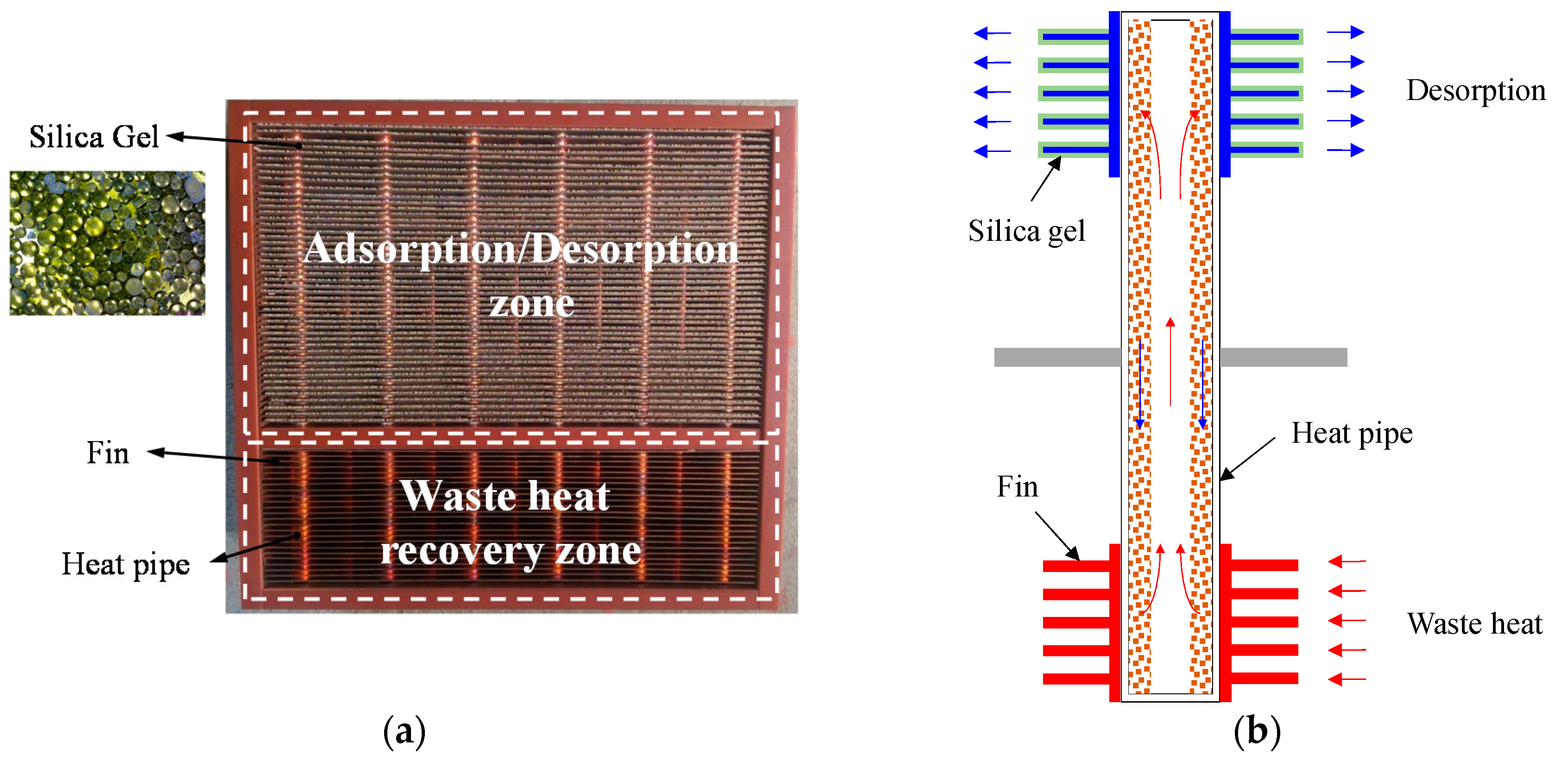
Since the thermal conductivity of most types of desiccant are usually poor, to remove the water absorbed in the desiccant by commonly used hot air blowing needs air of much higher temperature to ensure that the desiccant temperature is high enough to effectively regenerate. Coating desiccant onto a base of excellent thermal conductivity undoubtedly reduces the energy demand for heating the desiccant with a uniform temperature throughout. Therefore, this study uses the assembly of heat pipes and plate fins as the base material on which the desiccant is coated. The schematic diagram of the front view of the heat pipe-based desiccant device and one of the plate fins in the heat pipe-based desiccant device in this study are shown in
Figure 1a,b, respectively. The assembly of a total of 50 heat pipes with diameter of 8 mm and a total of 72 plates was used as the heat pipe-based desiccant device in dimensions of 250 mm × 231.6 mm × 100 mm, as shown in
Figure 2a. The pitch between the plate fins was 2.3 mm, and the number of the plate fins in the adsorption/desorption zone and the waste heat recovery zone was 48 and 24, respectively. The heat pipes and the plate fins were made of copper and soldered together to minimize the contact resistance. Numerous tablets of silica gel used as the absorbent were glued onto one of the surfaces of each plate fin in the adsorption/desorption zone using heat-resistant twin adhesive, as shown in
Figure 2a. The surface area of each plate fin was 204.24 cm
2, while the surface area of the absorbent material was 153.03 cm
2. The working principle of the heat pipe-based desiccant device is illustrated in
Figure 2b. During adsorption, the humid air flowed across the adsorption/desorption zone to remove the water vapor in the air by the absorbent, while the air flowed through the adsorption/desorption zone to carry the water adsorbed in the desiccant away by the recovered waste heat absorbed by the plate fins and then transferred by the heat pipes during desorption. Note that the thermal energy was provided by the thermostat to mimic the waste heat from the industrial process in order to establish the entire experiment in a room where the air humidity and temperature can be precisely controlled.
With the assumption of unsteady, one-dimensional airflow, as well as neglectable axial conduction and mass diffusion with constant properties of both air and desiccant, the energy and mass conservation equations for both the airflow and desiccant while the air flows through the passage between two plates coated with desiccant can be obtained [
22,
23] as follows.
Mass and energy conservation of airflow:
where
,
Ya,
Yw,
Ta, and
Tw are mass flow rate of the airflow, and the humidity ratio in air and in the solid desiccant surface, and the temperature of the air and the solid desiccant surface, respectively. Also,
h and
hm are the heat transfer coefficient and mass transfer coefficient between air and wall.
Pa,
Cpa, and
Cpv are the perimeter of the air channel, and the specific heat of air and water vapor.
Mass and energy conservation of desiccant:
where
W,
fm,
Pw,
Ta, and
Tw are the water content in the desiccant, the mass fraction of the desiccant layer, and perimeter of the solid desiccant, and the temperature of the air and wall coated with solid desiccant, respectively. Moreover,
Cpw and
Cpl are the specific heat of the solid desiccant and liquid water. Note that
Hads is the heat of adsorption. With an addition relationship between the water content in the desiccant,
W, and the humidity ratio of desiccant,
Yw, together with the appropriate boundary conditions, the five unknowns including
Ta,
Tw,
Ya,
Yw, and
W can be solved.
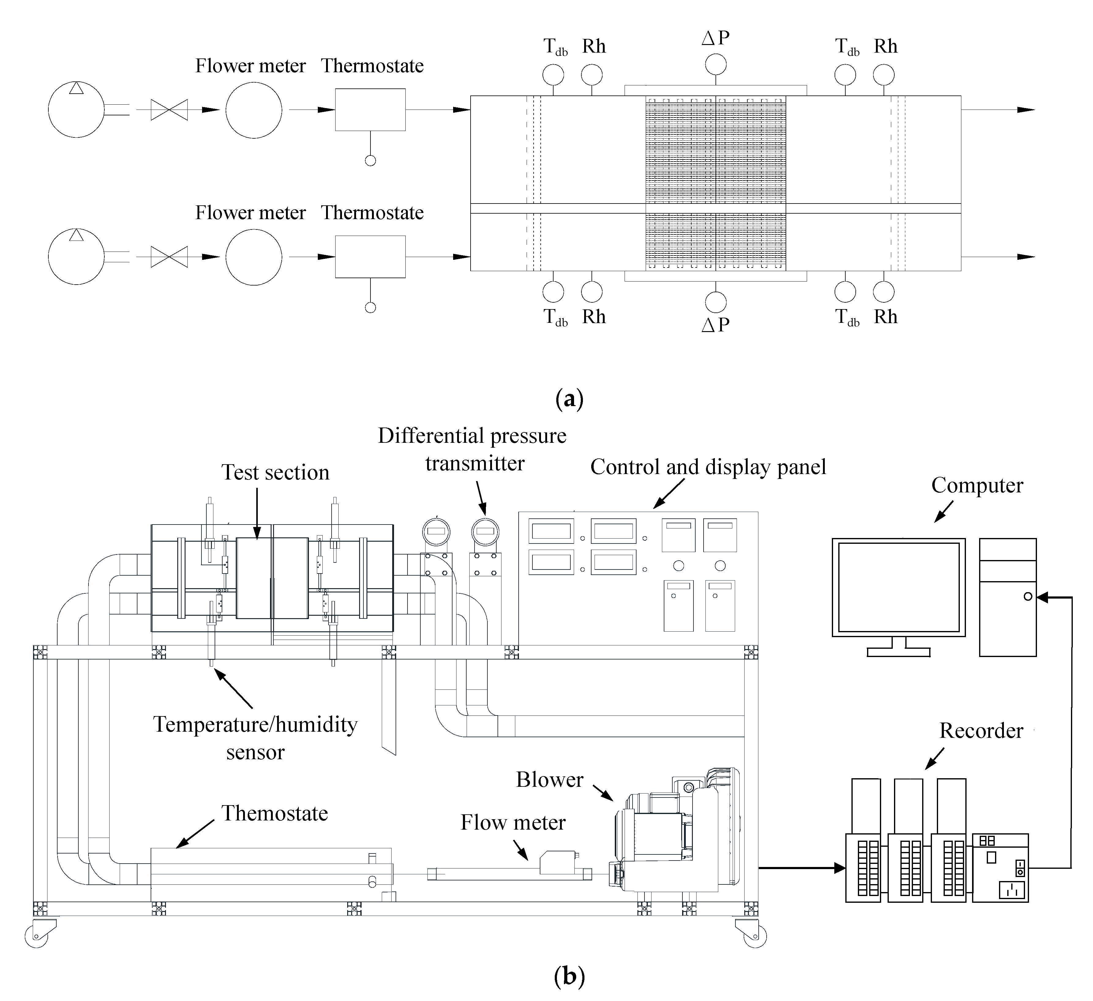
In order to evaluate the performance and characteristic of the heat pipe-based desiccant device, the experimental setup shown in
Figure 3 comprises a hot-air supply system, instruments for measuring the temperature, relative humidity, and pressure of the air, and a data acquisition unit. The hot-air supply system used a variable frequency centrifugal blower to force the air to flow through a thermostat to assure a fixed air temperature into the test section. As it enters the test section, the air first crosses a straightener to assure uniform airflow and then flows through the temperature/humidity sensor (Rotronic HC2-IE302-M) (Rotronic, New York, NY, USA), which measures the temperature and the relative humidity of air ranging from −100 °C to 200 °C with a resolution of ±0.1 °C, and 0% to 100% with a resolution of 0.8, respectively, to measure the temperature and the relative humidity of the air. The airflow rate was monitored by flowrate meters, SCHMIDT SS30.301 (SCHMIDT Technology GmbH, Georgen, Germany), that can measure the airflow rate ranging from 0.8 m
3/h to 229 m
3/h with a resolution of 0.3%. Several T-type thermocouples (OMEGA, Norwalk, CA, USA) were used to measure the temperature of the desiccant device with a resolution of ±0.1 °C, and a differential pressure transmitter (YOKOGAWA EJ110A) (YOKOGAWA, Tokyo, Japan) was also used to measure the pressure difference across the desiccant device with a resolution of 0.1 Pa. All measured signals were transmitted by a data acquisition unit (DATAQ instruments, GL-820) (DATAQ instruments, Akron, OH, USA) and recorded by a personal computer for further analysis. The experimental setup was located in a room in which the temperature and relative humidity of air could be steadily maintained at a specific value. The ambient temperature and relative humidity of air before entering the centrifugal blower were monitored by a temperature and humidity transmitter (SHINYEI THT-B121) (SHINYEI KAISHA, Kobe, Japan), which measures the temperature and relative humidity of air ranging from 0 °C to 100 °C with a resolution of ±0.1 °C, and 0% Rh to 100% Rh with a resolution of ±3% Rh, respectively.
Both the adsorption rate and desorption rate were estimated in terms of the air flowrate, the temperature, and relative humidity at both inlet and outlet for further performance evaluation of the heat pipe-based desiccant device under various ambient conditions. The test condition are listed in
Table 1. Both the adsorption rate,
, in units of g H
2O/h, and the desorption rate,
, also in units of g H
2O/h, were estimated by:
where
,
,
, and
are the air density, kg/m
3, mass flow rate of air, kg/h, and specific humidity, kg H
2O/kg, at the inlet and outlet of either the adsorption zone or the desorption zone, respectively. Furthermore, both the total amount of adsorption and desorption,
and
, respectively, in units of g H
2O, can be obtained by performing the following integral of the adsorption rate and the desorption rate, respectively, over the measured period of time:
where
and
are the measured period of time and the sampling interval, respectively. To analyze the energy consumption for desorption, an index,
SECdes (kJ/g H
2O), was defined as:
to indicate the power consumption for desorbing per unit mass of water moisture. The
is the power consumption during desorption in units of kJ, which can be estimated as follows:
where
,
, and
V are the instantaneous power (W), instantaneous current (A), and the voltage (V).
3. Results and Discussion
In order to reduce the negative impact of the ambient humidity on the dryer efficiency, a novel heat pipe-based desiccant device to dehumidify the air by adsorption was proposed and tested here. The desiccant device was tested under different conditions including varying air temperature, relative humidity of air, and airflow rate, as listed in
Table 1, to realize their effects on the characteristics of adsorption and desorption. The uncertainty [
24] of the adsorption rate and desorption rate at different instants in time is also provided in this table. Note that the “Max” uncertainty of the adsorption rate refers to the uncertainty of the adsorption rate at the beginning of the adsorption. Please refer to
Appendix A for detailed estimation procedure of the uncertainty. Finally, the benefit of using a heat pipe heat exchanger to recover waste heat on the energy consumption during desorption was also evaluated.
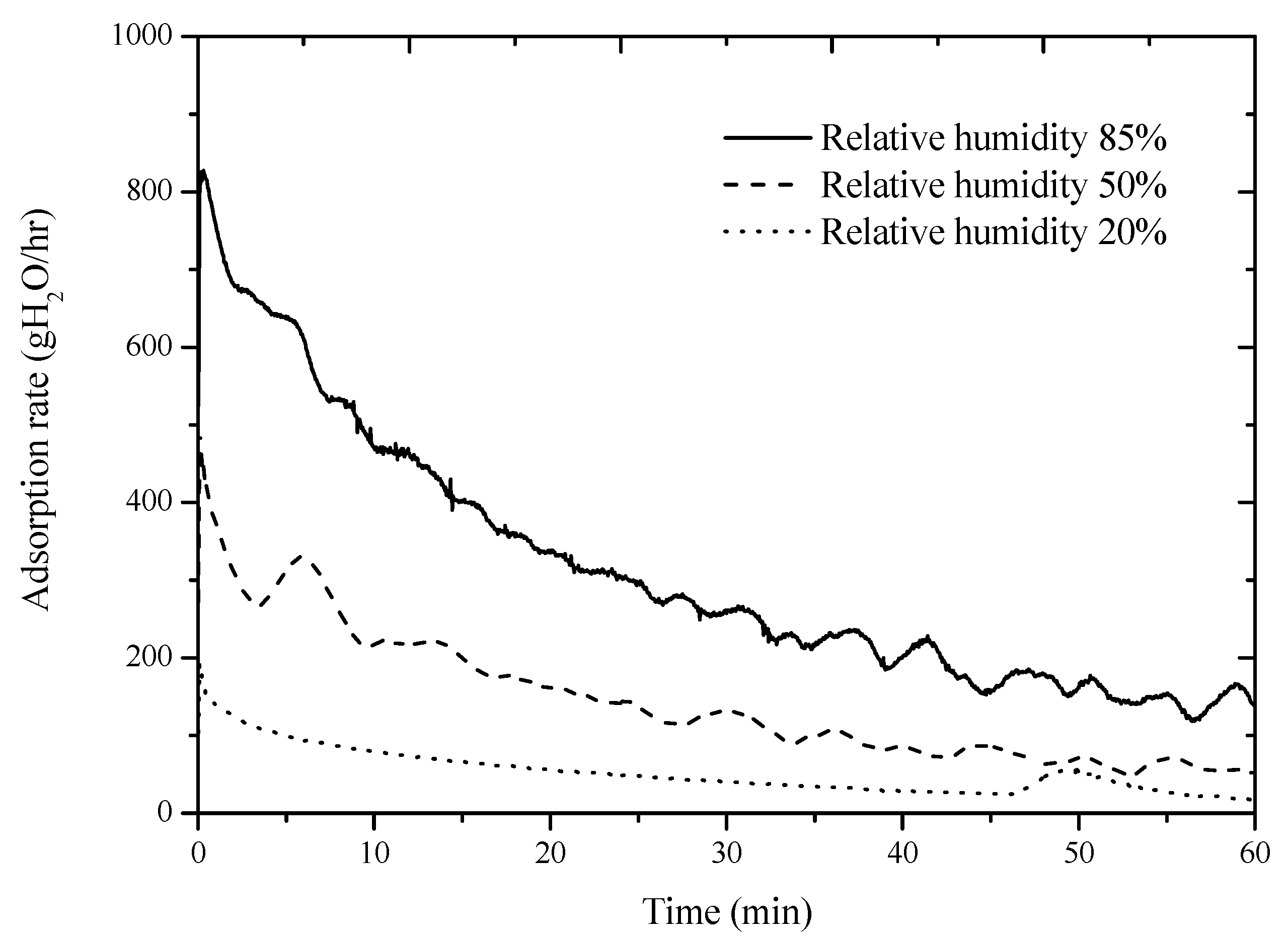
Figure 4 shows the variation of the adsorption rate of the desiccant device with time at a given ambient temperature of 15 °C and an airflow rate of 90 m
3/h at different relative humidity levels of air. It can be observed in
Figure 4 that the adsorption rate of the heat pipe-based desiccant device increased as the relative humidity of air increased, because the higher parital pressure of water vapor in air at a higher relative humidity contriubtes to the better adsorption of the desiccant. For instance, the average adsorption rate over 1 h revealed in
Figure 4 was 53.02 g H
2O/h, 144.03 g H
2O/h, and 312.04 g H
2O/h with the relative humidity of air of 20%, 50% and 85%, respectively. The psychrometric chart of moist air indicates that the specific humidity of moist air is 2.1 g H
2O/kg, 5.3 g H
2O/kg, and 9 g H
2O/kg as the relative humidity of moist air is 20%, 50%, and 85%, respectively.
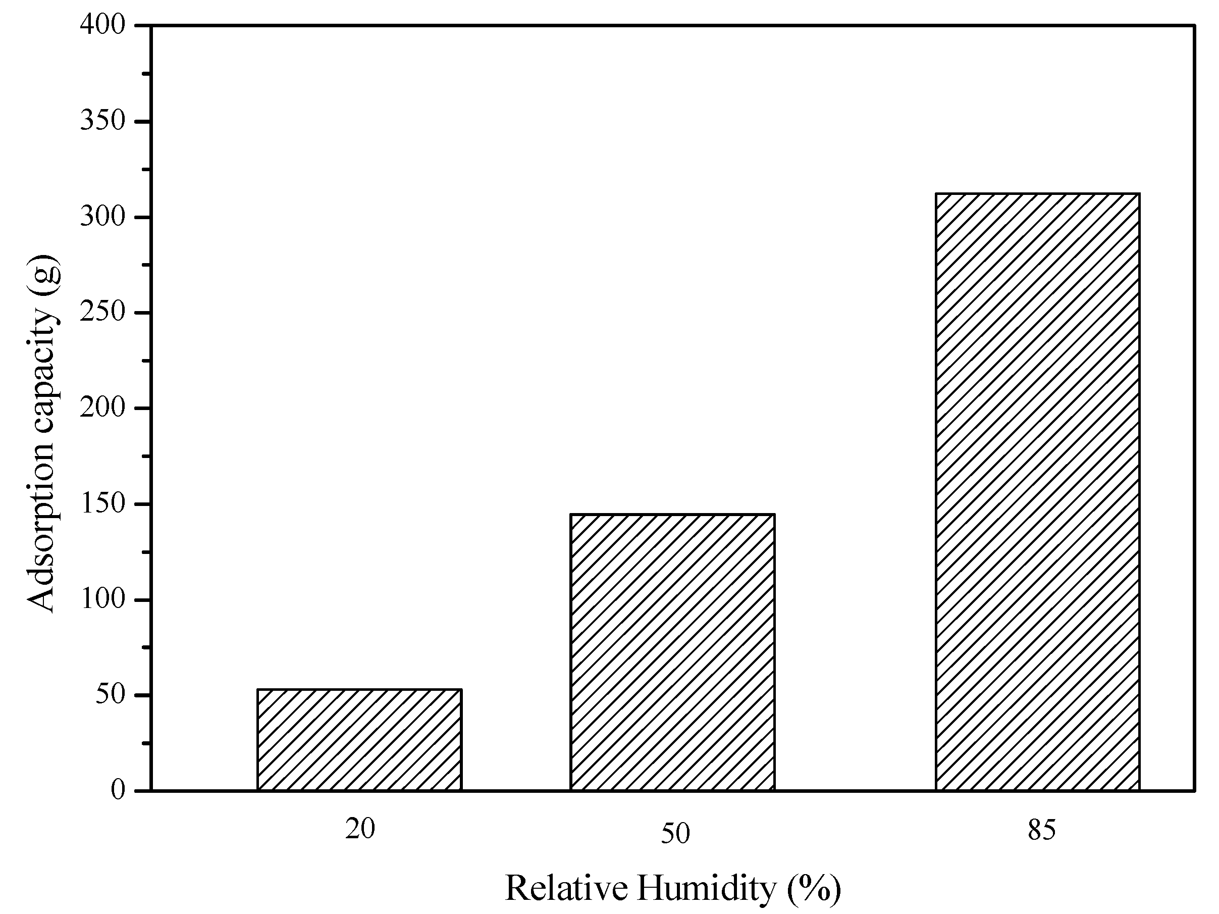
Figure 5 shows the total amount of adsorption for 1 h at different relative humidity levels of air at a fixed ambient temperature of 15 °C and an airflow rate of 90 m
3/h. The results in
Figure 5 show that the total amout of adsorption for 1 h at a relative humidity level of 20%, 50%, and 85% is 53.05 g, 144.59 g, and 312.30 g, respectively. Therefore, from the results in both
Figure 4 and
Figure 5, it can be concluded that both the adsorption rate and the total amount of the aborption increased as the relative humidity of air increased.
Besides the variation of the adsorption rate with time at a given relative humidity of air (85%), the adsorption rate at different ambient temperatures with a fixed airflow rate of 90 m
3/h was is shown in
Figure 6. The results in
Figure 6 show that the adsorption rate increased as the abmient temperature increased. The instantaneous adsorption rate at the beginning of the absortpion was 827.61 g H
2O/h and 1443.1 g H
2O/h at an ambient temperature of 15 °C and 25 °C, respectively. In addition, the adsorption rate of those cases coincided after 25 minutes adsorption and then gradually approached zero together within the rest of the adsorption period. Because the mass of the water vapor contained in the moist air at a fixed relative humidity of air increases as the air temperature increases, the amount water absorbed by the desiccant device also increases at a high ambient temperature.
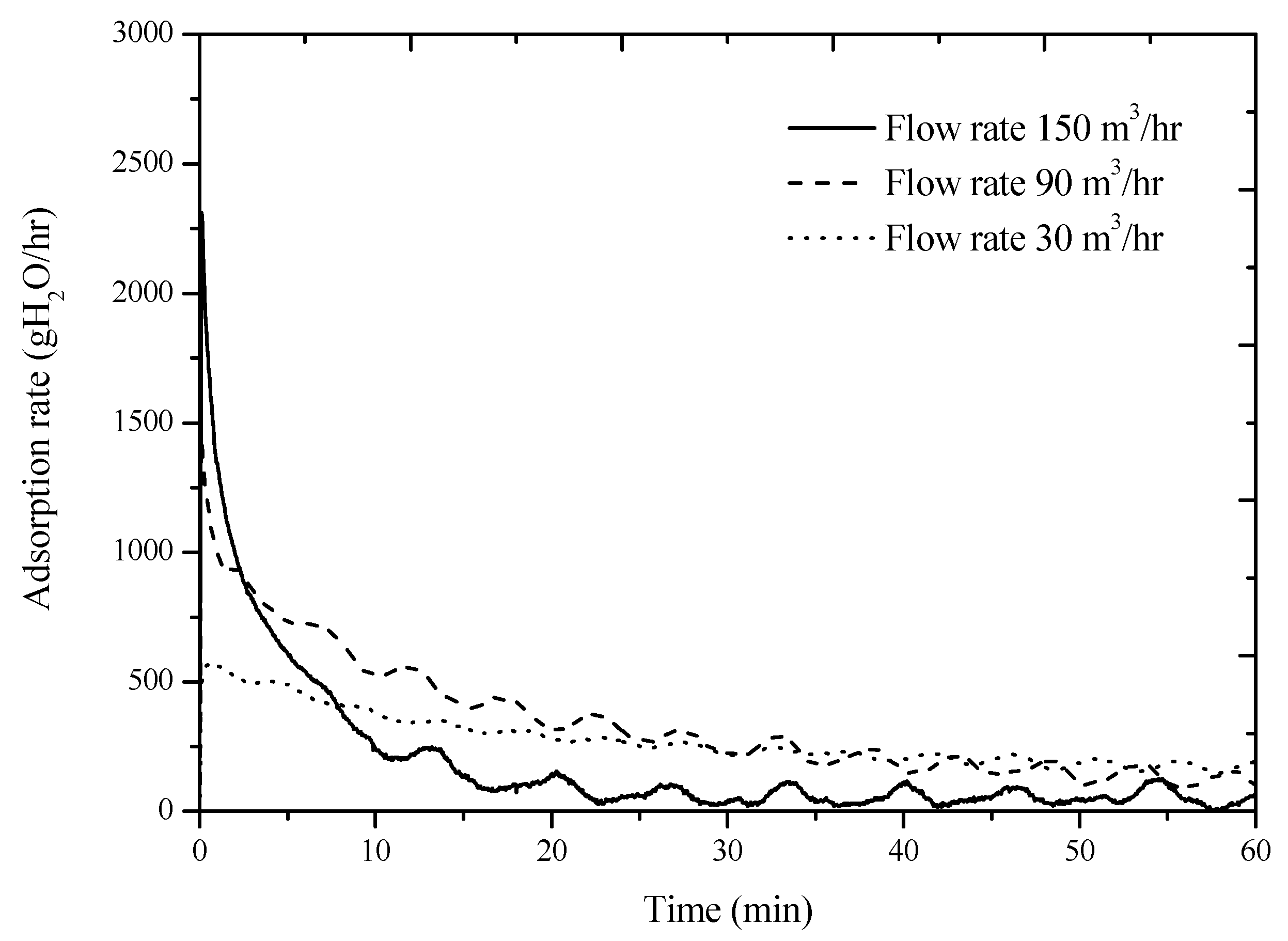
Figure 7 shows the variation of adsorption rate with time at a fixed ambient temperature (25 °C) and relative humidity of air (85%) at various airflow rates. The results in
Figure 7 show that the desiccant device demostrated a high adsorption rate at a high airflow rate at the beginning of the adsorption. However, the high adsorption rate of the desiccant device causes a rapid increase of the water amount absorbed in the desiccant. Since the water concentration gradient at the desiccant surface rapidly reduces at the beginning of the adsorption at a high airflow rate, the adsorption rate of the desiccant device dramatically degrades afterward. The curve in
Figure 7 indicates that water vapor in the moist air is no longer absorbed by the desiccant because the adsorption rate has already reached zero at 0.4 h at a airflow rate of 150 m
3/h. Although the adsorption rate at a low airflow rate is lower than that at a high airflow rate, the adsorption time lasts longer.
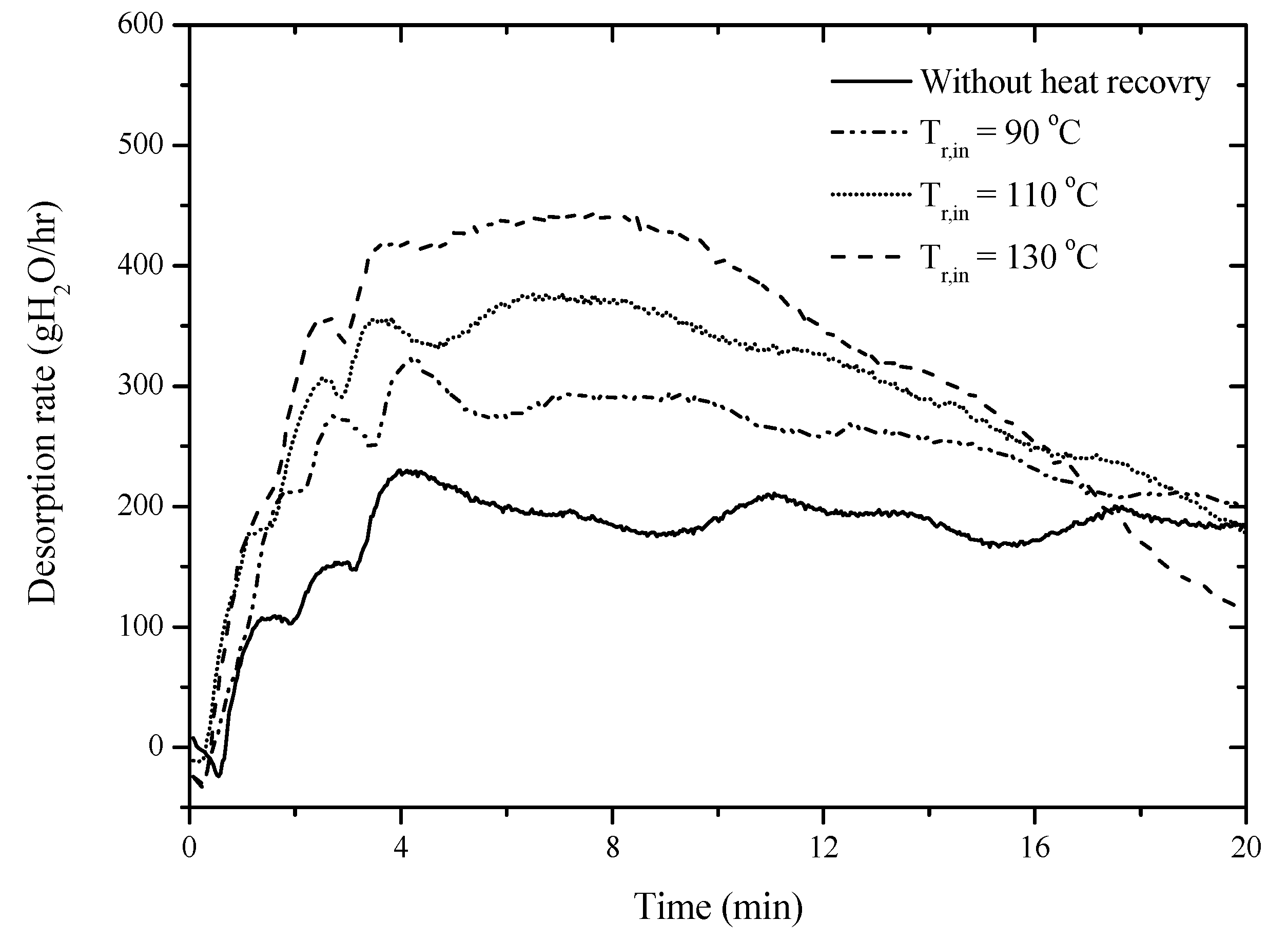
Although using the desiccant device effectively reduces the relative humidity of air and thus reduces the energy consumption during drying, the regeneration of the desiccant device has to consume additional energy. The heat pipe-based desiccant device developed in this study is able to desorb water contained in the desiccant device using waste heat recovered from the industrial fabrication process, so that the energy consumption for desorption can be saved.
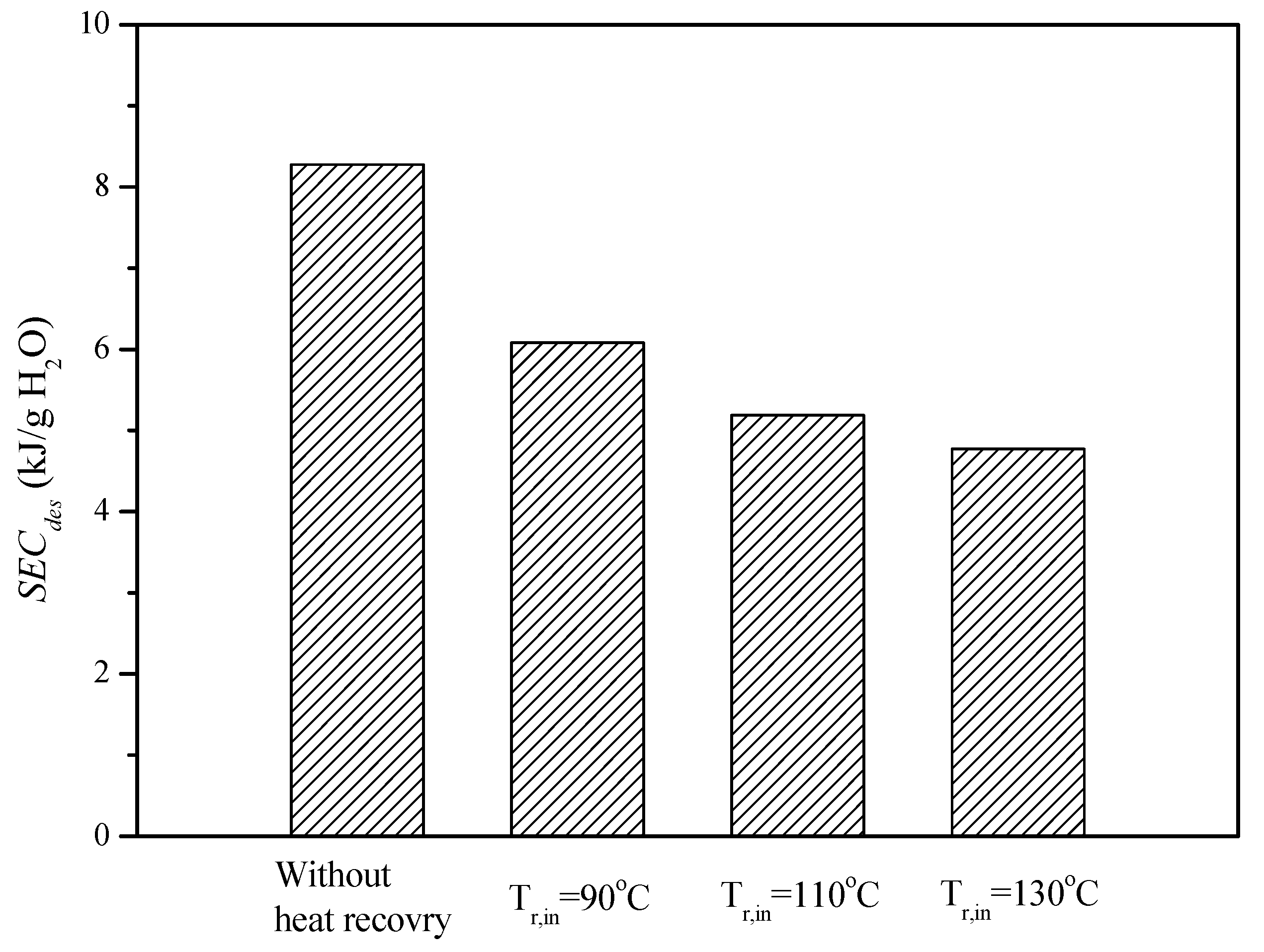
Figure 8 shows the desorption rate of the desiccant device at heat recovery temperatures of 90 °C, 110 °C, and 130 °C to demonstrate the effectiveness on energy saving. This shows that the higher the heat recovery temperature, the faster the desorption rate of the heat pipe-based desiccant device. Furthermore, the specific energy consumptions as defined in Equation (10) to quantitatively express the energy consumption during desorption of the heat pipe-based desiccant device at different heat recovery temperatures is shown in
Figure 9. It was found that the specific energy consumption was 8.27 kJ/g H
2O and 4.77 kJ/g H
2O, without employing recovered heat and with heat recovered at 130 °C, respectively. A dramatic decrease in energy consumption during desorption was revealed as the waste heat was employed.


