Article

A Novel Active Online State of Charge Based Balancing Approach for Lithium-Ion Battery Packs during Fast Charging Process in Electric Vehicles

1
Faculty of Science, Engineering and Technology, Swinburne University of Technology, Hawthorn, Victoria 3122, Australia
2
School of Electrical Engineering and Automation, Anhui University, Hefei 230601, China
*
Authors to whom correspondence should be addressed.
Energies 2017, 10(11), 1766; https://doi.org/10.3390/en10111766
Submission received: 15 September 2017 / Revised: 25 October 2017 / Accepted: 26 October 2017 / Published: 2 November 2017

Abstract

:
Non-uniformity of Lithium-ion cells in a battery pack is inevitable and has become the bottleneck to the pack capacity, especially in the fast charging process. Therefore, a balancing approach is essentially required. This paper proposes an active online cell balancing approach in a fast charging process using the state of charge (SOC) as balancing criterion. The goal of this approach is to complete pack balancing within the limited charging time. An adaptive extended Kalman filter (AEKF) is applied to estimate the pack cell SOC during the charging process to obtain accurate results under modeling errors and measurement noises. To implement the proposed AEKF, only one additional current sensor is required to obtain the current of each cell required for the SOC estimation. An experimental platform is established to verify the effectiveness of the proposed approach. The results show that the proposed balancing approach with the SOC as a balancing criterion can overcome the challenges of non-uniformity and flat voltage plateau and charge more capacity into a LiFePO4 battery pack than those with the terminal voltage as a balancing criterion in the fast charging process.

Highlights:

  • Adaptive extended Kalman filter (AEKF) is employed to estimate the pack cell state of charge (SOC) in real time, which is used as a balancing criterion to equalize cells in a LiFePO4 battery pack in the fast charging process.
  • Only one additional current sensor in the chosen balancing circuit is required to accurately estimate pack cell SOC, leading to low cost implementation.
  • Balancing in the fast charging process based on online estimated SOC overcomes non-uniformity and allows more pack capacity to be charged.
  • Experimental platform is established to demonstrate that the performances based on the SOC criterion is better than those based on the terminal voltage criterion in terms of extra charged capacity of 2.07 Ah, equivalent to 13% of the nominal capacity of the chosen battery pack.

1. Introduction

Due to high energy density, long life cycle and low self-discharge rate, lithium-ion batteries have become one of the main power candidates for electric vehicles (EVs) [1]. However, power and energy demand in EVs is high and the voltage of battery packs in EVs is normally above 300 V, thus battery cells are required to connect in series (or parallel) to form a battery pack for meeting energy and power demand. For those serially connected cells, an imbalance of state of charge (SOC) will occur [2,3]. As a consequence, the cells in the pack cannot reach the fully charged states simultaneously. The cell with the least chargeable capacity that is fully charged first determines the pack capacity. Active cell balancing is required to equalize cell SOCs to improve pack capacity [4].
Recently, active cell balancing is widely used in maintenance conditions in which the charging or discharging stops when the balancing operates [5,6,7,8]. In maintenance conditions, there is no strict restriction of balancing time and balancing speed is not critical. Active cell balancing is also used in the charging and discharging conditions. In such conditions, balancing study is to fully use the limited pack capacity, which requires the completion of balancing before the end of the charging or discharging process to obtain the maximum pack capacity. Therefore, the balancing time, which is decided by the charging or discharging time, is limited and the balancing speed is critical. For different charging and discharging conditions, the fast charging condition gives the most severe challenge due to a short charging time. Thus, balancing in a fast charging process (e.g., the charging time is less than 1 h) is only discussed in this paper. The full utilization of the short charging time is largely decided by the balancing criterion, which can be divided into two groups: voltage based balancing criterion and SOC or capacity based balancing criterion [9,10,11,12].
The terminal voltage as the balancing criterion is widely used in commercial EVs as it can be easily measured and implemented in all kinds of balancing circuits. When it is applied to battery types such as a LiFePO4 battery pack with a flat charge and discharge plateau, balancing may not occur during most of the charging or discharging time that has flat voltage outputs in the range of the SOC from about 20% to 90% as shown in Figure 1.
Battery SOC is the alternative criterion for balancing operation [12,13,14]. When the SOC is used, the accuracy of the SOC decides the final effect. Many accurate SOC estimations have been proposed in literature. The extended Kalman filter [15,16,17] was proposed for lithium-ion cells, where accurate battery model and measurement were required. In [18,19,20], sliding mode observer based SOC estimation method was taken and the robustness was improved. Different working conditions are considered with an equivalent circuit model in [21] to increase the accuracy of the SOC estimation. To deal with the modelling error and uncertainty, many adaptive methods are proposed [22,23,24]. However, most of these methods deal with the single cell and the challenges that are unique to the battery pack are not considered. Accurate online SOC estimation needs reliable cell current measurement. This is difficult for the battery pack in the balancing process due to the existence of balancing current and this challenge is not solved in literature [25,26,27] based on author’s best knowledge. The SOC is applied as the balancing criterion in [12], where the balancing is operated in maintenance conditions.
In this paper, a novel active online state of charge based balancing approach during fast charging process is proposed to equalize cells in a LiFePO4 battery pack, where only one additional current sensor is required to obtain the current of each cell for the SOC estimation with the chosen flyback based balancing circuit. This approach can potentially apply to balance the pack of supercapacitors [28], which are the important candidates to enhance charge and discharge power capability for EV energy storage systems. The remainder of this paper is organized as follows: Section 2 explains the balancing system. The balancing circuit and the current calculation for each cell in the pack is explained first. Then, an adaptive extended Kalman filter (AEKF) for the SOC estimation is presented. Finally, the battery model and parameters extraction used for the SOC estimation is explained. In Section 3, the proposed active balancing approach based on the SOC are experimentally verified and compared with the active balancing approach based on terminal voltage. The conclusions are presented in Section 4.

2. Balancing System for Fast Charging Process of a Battery Pack

A balancing system is designed in this section based on the challenges presented in the Introduction. First, a flyback balancing circuit is chosen and the method to obtain cell current is designed. The next step is to apply the SOC as the balancing criterion in the fast charging process, which targets complete balancing within one hour. To achieve this, the AEKF is presented to handle the modelling uncertainty and measurement noises in the battery pack. Finally, the battery modelling and parameter extraction used for the AEKF are briefly explained.

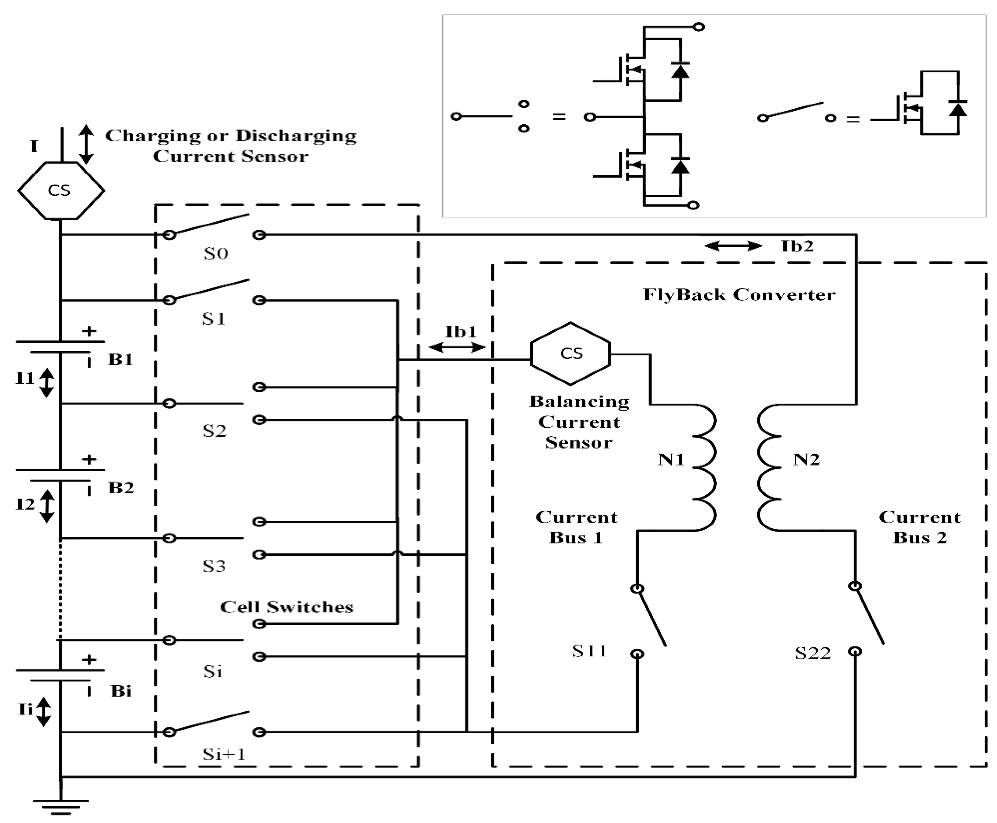
2.1. Current Calculation of Each Cell for SOC Estimation with Fly-Back Converter Based Balancing Circuit

Based on the main balancing components, active balancing circuits can be divided into three groups: capacitor based balancing circuits [11,29,30,31,32,33,34,35,36], inductor based balancing circuits [5,8,27,37,38,39,40,41,42,43,44,45] and transformer based balancing circuits [6,7,25,26,46,47,48,49,50,51]. Not every active balancing circuit can use SOC as the balancing criterion due to the nature of the balancing components and the topology of the balancing circuits. In capacitor based balancing circuits, the terminal voltage difference among the cells in the pack determines the peak amplitude and the direction of balancing currents. Thus, there is no benefit to use the SOC as a balancing criterion in these circuits. In inductor and transformer based balancing circuits, generally the balancing current in the circuits can be controlled to achieve the desired value, and the SOC can always be used as the balancing criterion except that some transformer based balancing circuits are specially designed to use terminal voltage as the balancing criterion to equalize the battery pack.
A flyback converter based balancing circuit shown in Figure 2 [47], which is one kind of transformer based balancing circuits, has been chosen to implement the balancing operation in this study.
In this flyback balancing circuit, only one additional current sensor is added to calculate the current I i ( t ) of each cell in the battery pack during the balancing operation, namely the balancing current sensor measures the balancing current I b 1 , the existing charging current sensor measures the charging current I ( t ) , and then current of each cell I i ( t ) is calculated by:
I i ( t ) = { I ( t ) I b 1 + I b 2 Balanced   Cell I ( t ) + I b 2 Other   Cells
The balancing current sensor measures the balancing current in the low voltage side to improve the accuracy of current measurement and the current ( I b 2 ) in the high voltage side is calculated by:
I b 2 = ( N 1 / N 2 ) I b 1 η
where N 1 and N 2 are the ratio of the flyback transformer and η is the efficiency of the flyback converter. In the balancing operation, the switches are turned on/off at high frequency, so the balancing current of each cell is averaged first and then superimposed with the charging current to obtain I i ( t ) , which is used in the AEKF for the SOC estimation in each step.
This balancing circuit can select any cells in the pack for balancing operation through a switch matrix in two operation modes: the cell to pack mode (CTP) and the pack to cell mode (PTC). In the CTP mode, the cell with the highest SOC or terminal voltage is discharged and releases charges back to the pack via the flyback converter. In the PTC mode, the cell with the lowest SOC or terminal voltage is identified and the charges from the pack are injected into this cell.
In the experiment, the converter is running in discontinuous conduction mode with the peak balancing current limited to 1.5 A. The duty cycle of the pulse width modulation (PWM) control signal for the metal–oxide–semiconductor field-effect transistor (MOSFET) is 0.4 and the frequency is 10 kHz. The sampling frequency of the current sensor is set as 50 kHz. The inductor values of the flyback converter are 70 uH and 930 uH for the low voltage side and high voltage side, respectively.

2.2. Adaptive Extended Kalman Filter for SOC Estimation

The Coulomb counting is a widely-used approach for the SOC estimation for ease of implementation. The drawbacks are that it cannot decide the initial SOC and its estimation errors accumulate over time. The battery OCV is taken to calibrate the SOC [51]. Unfortunately, it is hard to measure the OCV in real time and the small OCV error may lead to significant SOC difference, particularly for the flat voltage plateau of a LiFePO4 battery. In this study, the AEKF is applied to estimate the SOC.
The AEKF for the SOC estimation combines the advantages of the Coulomb counting method and the battery OCV based SOC estimation method [52]. The noises and errors are taken into consideration in the filter gain to obtain the optimal estimation results. In the battery pack, the parameters are extracted once and used in the later estimations. This leads to accumulated modelling error. A fading memory factor is used in the AEKF [53] to increase the adaptiveness for the modelling errors. This fading memory factor serves to increase the uncertainty of the state estimation and give more credence to the measurement.
When process errors and measurement noises are considered, the state space equation of the battery dynamic system can be generalized as:
{ x k = f ( x k , u k , ω k ) y k = h k ( x k , v k )
{ ω k ~ ( 0 , Q k ) ν k ~ ( 0 , R k )
where x is a state vector [ Z k   V p c k   V p e k ] T ; y is an output vector that represents the battery terminal voltage; ω k is the process Gaussian noises with the covariance of Q k ; and ν k is measurement Gaussian noises with the covariance of R k .
The Jacobian matrixes of partial derivatives from the state space equation are listed as follows:
A k 1 = f x | x ^ k 1 , B k 1 = f u | x ^ k 1 and   H k = h x | x ^ k .
Then, the linearized state equation including noises could be generalized as:
{ x k = A k 1 x k 1 + B k 1 u k 1 + ω k 1 y k = H k x k + ν k E ( ω k ω j T ) = Q k δ k j E ( ν k ν j T )   = R k δ k j E ( ω k ν j T )   = 0
The steps for optimal SOC estimation with the AEKF can be summarized as follows.
Step (1): Initialization: the initial x 0 is estimated as a Gaussian random vector with mean of x 0 and covariance of P 0 :
{ x ^ 0 + = E [ x 0 ] P 0 + = E [ ( x 0 x ^ 0 + ) ( x 0 x ^ 0 + ) T ]  
Step (2): Time update (from time ( k 1 ) + to time k ): the current state estimation is obtained based on the state estimation and its covariance in the previous step:
P ˜ k = α 2 A k 1 P ˜ k 1 + A k 1 T + Q k 1 x ^ k = A k 1 x ^ k 1 + + G k 1 u k 1
where P ˜ k = α 2 k P k , P ˜ k 1 + = α 2 ( k 1 ) P k 1 + , α is the fading memory factor and its value is equal or higher than 1. It is set as 1.0001 in this study.
Sept (3): Kalman gain update:
K k = P ˜ k H k T ( H k P ˜ k H k T + R k ) 1
Sept (4): Discrete measurement update: the estimated state x ^ k is updated when the measurement is available. The covariance is also updated and they are presented by:
x ^ k + = x ^ k + K k ( y k h k ( x ^ k , 0 , t k ) ) P ˜ k + = ( I K k H k ) P ˜ k ( I K k H k ) T + K k R k K k T
where P ˜ k + = α 2 k P k + .
The initial parameters of the AEKF are obtained based on empirical experience. For example, the initial parameters of the battery cell for the pulse constant current (PCC) test are tuned to be:
x 0 = [ 0.1 0.01 0.01 ] , R 0 = [ 20 ] ,
Q 0 = [ 0.05 0 0 0 0.2 0 0 0 0.2 ]   and   P 0 = [ 100 0 0 0 0.01 0 0 0 0.01 ] .

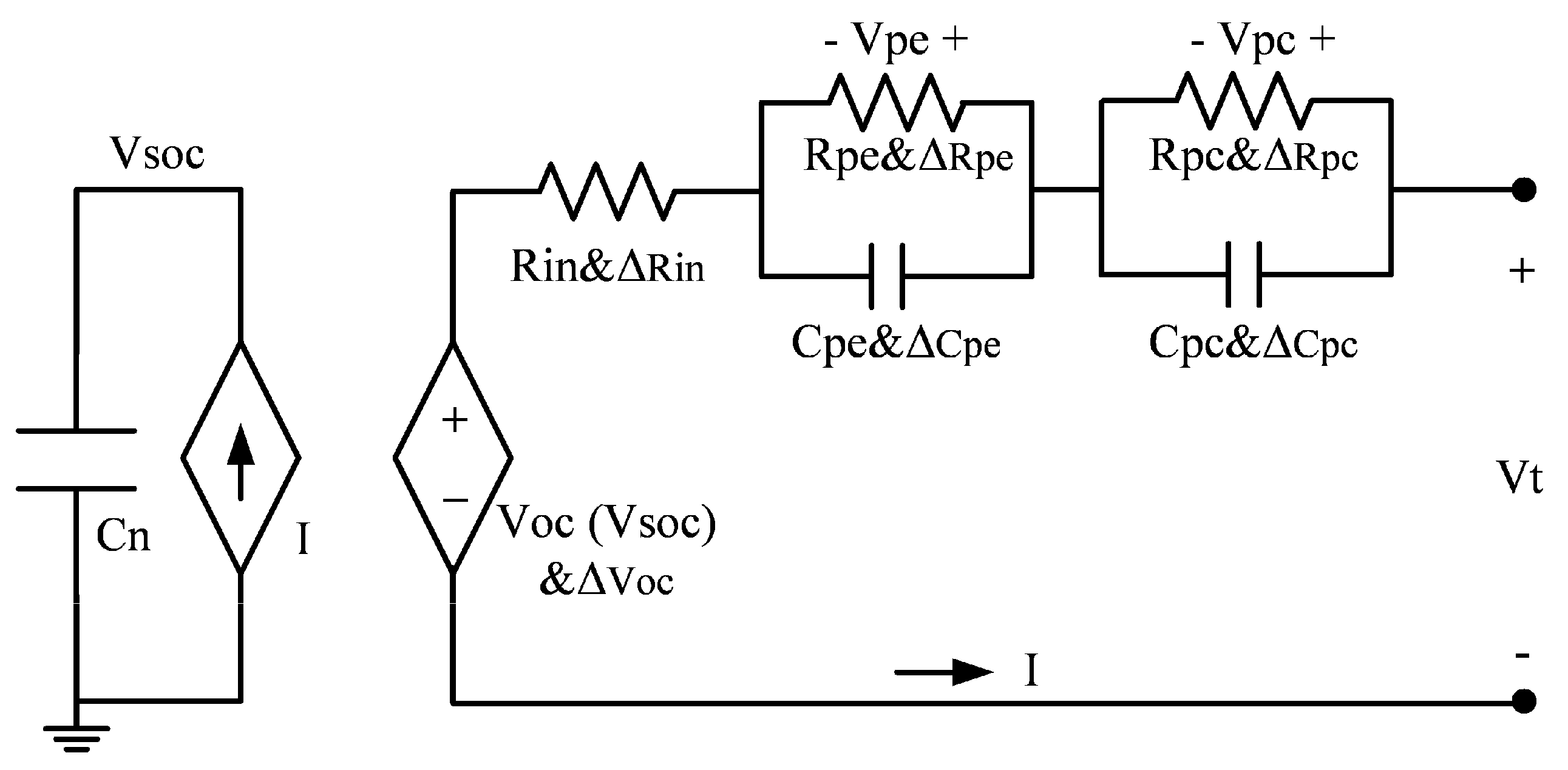
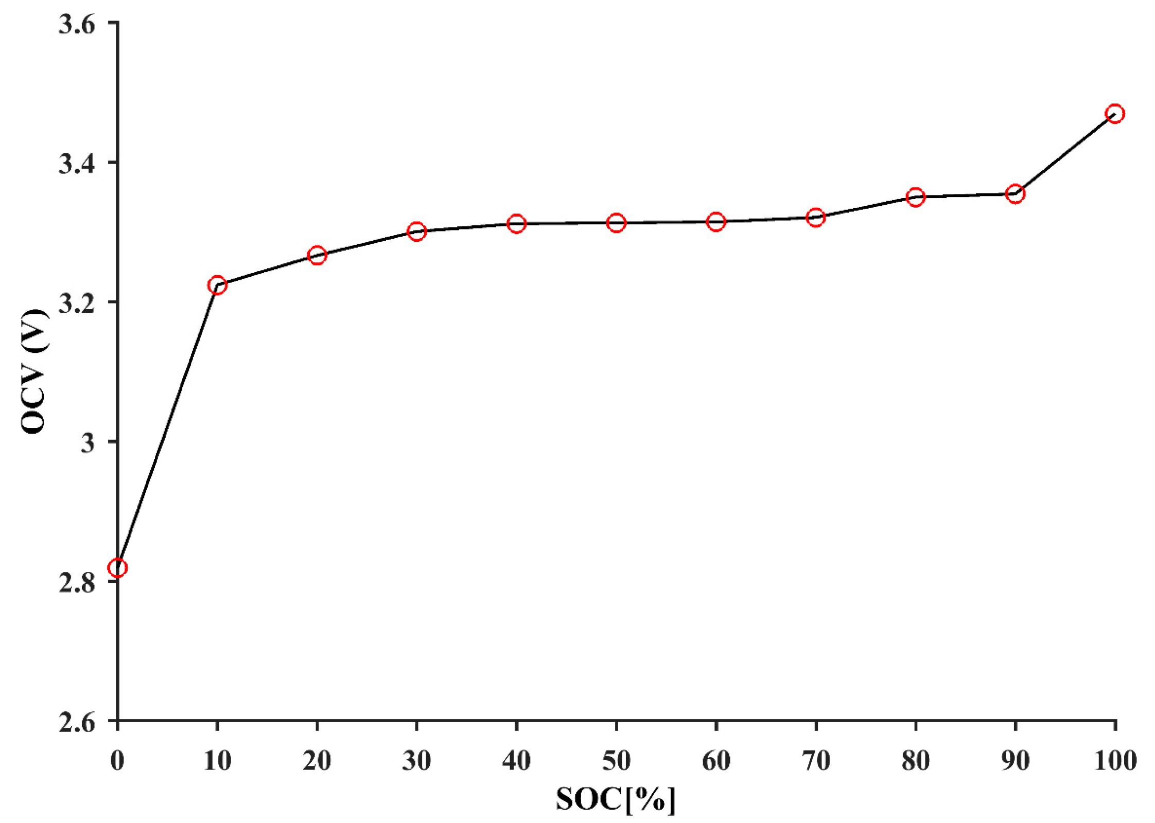
2.3. Battery Modelling and Parameters Identification

To obtain the state space equation of the battery cell used in the SOC estimation, the battery equivalent circuit model (ECM) as shown in Figure 3 is adopted to accurately reflect dynamic behaviors of LiFePO4 batteries [22,54,55]. In the ECM, V t and I represent battery terminal voltage and current, respectively; R i n is an internal resistance characterizing the instant voltage drop; a parallel branch of a resistance R p e and a capacitance C p e represents electrochemical polarization and the other parallel branch represents concentration polarization; these two branches reflect the short-term and long-term transient responses of the battery. The symbols Δ V o c , Δ R i n , Δ R p e , Δ C p e , Δ R p c , and Δ C p c are associated with process errors and noises.
The capacitance C n represents the total charge stored in the battery by converting the capacity in Ah into the charge in Coulomb:
C n = 3600 C b a t t e r y
where C b a t t e r y is the battery capacity in Ah. The voltage V S O C across the capacitance C n represents the SOC and its value is set between 0 and 1 V corresponding to 0% and 100%.
The SOC is a relative quantity that describes the ratio of the remaining capacity to the normal capacity for the battery. It is defined as:
Z ( t ) = Z ( 0 ) + ( 1 / C n ) t 0 t I ( τ ) d τ
where Z(0) is the initial SOC of the battery. The time deviation of the SOC gives:
d Z d t = I / C n
According to Kirchhoff voltage law, the battery terminal voltage and the derivatives of polarization voltages in Figure 2 are determined by:
V t = V o c ( Z ) + V p e + V p c + I R i n
d V p c d t = V p c / ( R p c C p c ) + I / C p c
d V p e d t = V p e / ( R p e C p e ) + I / C p e
Due to the fast sampling rate, the change rates of charging currents are taken as zero in each sampling period. Solving the current I in Equation (12) and substituting it into Equation (13) leads to the equation for the derivative of the SOC.
Thus, the state-space equation of the battery is developed as follows:
{ d Z d t = α 1 [ V t V o c ( Z ) + V p c + V p e ] d V p c d t = α 2 V p c + b 2 I d V p e d t = α 3 V p e + b 3 I
where: α 1 = 1 / R i n C n , α 2 = ( 1 / R p c C p c ) , α 3 = ( 1 / R p e C p e ) , b 2 = 1 / C p c and b 3 = 1 / C p e .
The model parameters shown in Figure 3 are obtained by fitting the experimental data from the PCC test as shown in Figure 4. A LiFePO4 battery (A123 ANR26650) with the nominal capacity of 2.3 Ah was tested under room temperature. The cell was first fully discharged with 2.3 A until the voltage reaches 2V. Then, the cell rested for one hour to get the initial OCV. After that, the current profile of the PCC as shown in Figure 4a was used to charge the battery, where one-hour rest was inserted to obtain the OCV for every 10% SOC increment in charging process. Figure 4b shows the transient voltage corresponding to the PCC. From Figure 4a,b, the relationship between the OCV and the SOC is obtained and shown in Figure 5. This OCV data can be fitted by Equation (17) and its coefficients are listed in Table 1:
V o c ( Z ) = λ 0 + λ 1 Z + λ 2 Z 2 + λ 3 Z 3 + λ 4 Z 4 + λ 5 Z 5 + λ 6 Z 6 + λ 7 Z 7
where λ i ( i = 0 , , 7 ) are the coefficients of the OCV versus the SOC [56].
The part circled in red of Figure 4b is zoomed in in Figure 4c. Since the battery model parameters corresponding to the pulse at the SOC of 70% cause the highest SOC estimation error, the parameters obtained at this SOC will be applied in the model for the SOC estimation.
Intuitively, the relaxation voltage in Figure 4c can be represented by:
V t ( t ) = V o c V p e exp ( t / τ p e ) V p c exp ( t / τ p c )
where Δ V t represents the voltage drop caused by the internal resistance R i n , so it can be calculated by:
R i n = Δ V t / I
Then, a root mean square error method is used to determine V p e , V p c , τ p e , and τ p c in Equation (18) [22], and the resistances and capacitances in the two parallel branches are calculated by
{ R p e = V p e / I R p c = V p c / I C p e = τ p e / R p e C p c = τ p c / R p c  
All of these parameters were substituted into Equation (18) to calculate the transient voltage. Then, the transient responses obtained from the equation were compared with the experimental results in Figure 4d. It shows a good agreement. Table 1 lists all these parameters.

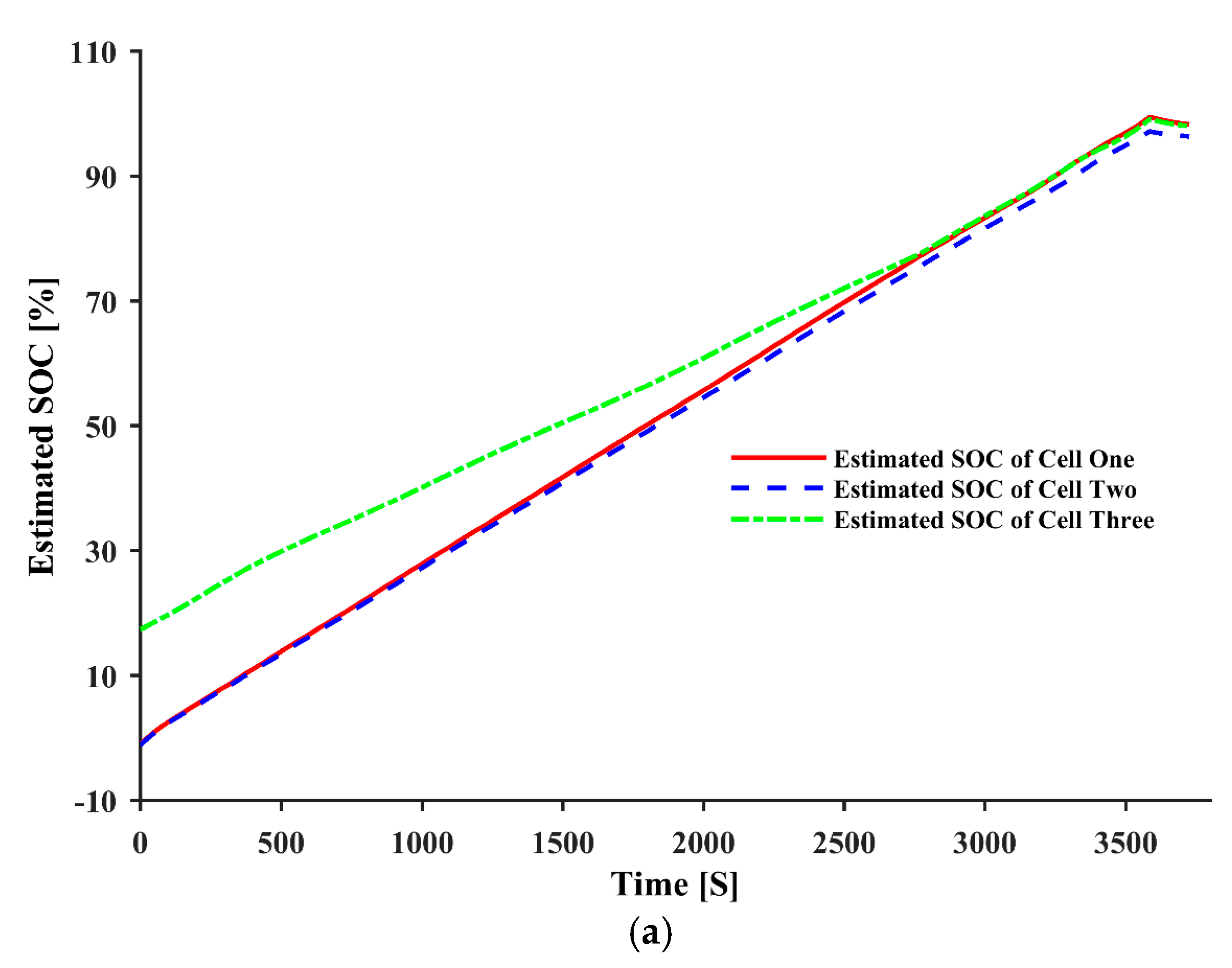
3. Experimental Verification

To evaluate the performance of the proposed active balancing approach, a testing platform for active cell balancing was established, as shown in Figure 6. The prototype mainly consists of a battery pack charger, a serially-connected battery pack, a flyback converter-based balancing circuit, an National Instruments (NI) controller, an Arbin BT2000 (Arbin Instruments, College Station, TX, USA), a power supply and a computer. The battery pack charger is a Sorensen programmable power supply (Berwyn, PA, USA), which can set the charging current and voltage. The battery pack is made of three A123 LiFePO4 battery cells connected in series and their specifications are listed in Table 2. The NI controller consists of a field-programmable gate array (FPGA) module and a real-time control module. The FPGA module is responsible for the measurement of the current and terminal voltage of each cell in the battery pack and the control of the switches for the balancing circuit. The real-time module is the hardware implementation of the AEKF for the SOC estimation algorithm and the balancing control algorithm, which were developed using the LabVIEW program (Version 2012, NI, Austin, TX, USA). The Arbin BT2000 is responsible for the initialization of each single cell before the charging process starts. The power supply supports the NI controller and the balancing circuit. Finally, the computer is responsible for data storage and analysis as well as being the control interface of the NI controller. It also sets the charging algorithm for the battery pack charger. It should be noted that, in a commercial battery pack in EVs, normally the battery cells are connected in parallel to increase the capacity and these parallel-connected cells are called a battery module. To increase the voltage, many of these modules are connected in series to form the battery pack [57].
The SOC estimation for three cells in this study is used as the balancing criterion to carry out battery pack balancing in real time. To complete the balancing operation by the end of fast charging process, the quick estimation of the SOCs for three cells is essential. The statistical variation of the battery cells is inevitable. Obtaining the parameters of the battery models used in SOC estimation for each cell takes time and a heavy calculation load. Therefore, the model parameters of one cell in Table 1 and the OCV versus the SOC in Figure 5 are used to estimate the SOCs for three cells. The robust AEKF is used to estimate the SOCs for these three cells. The comparison of the estimated SOCs with the SOCs using Coulomb counting from the experimental data shows that the SOC estimations only have an error of less than 2%, which is quite accurate even with the modelling errors due to the above assumption. The true initial states of three cells were, respectively, 0%, 0% and 20% SOCs to create an imbalance scenario, and the Arbin BT2000 was used to fully discharge the first, second and third cells and then only the third cell was charged to 20% SOC. To validate the robustness of the AEKF for SOC estimation, the initial states of three cells for the battery model were unknown and set to the wrong values of 15% SOC. A resting time was allowed for the convergence of the SOC estimation of each cell before the charging process started. In the charging process, the balancing operation commenced when the maximum SOC difference was 2%. As a trade-off between charged pack capacity and charging time, the battery pack stopped charging when the voltage of any battery cell reached the cut-off voltage (3.6 V for the selected battery cell). Figure 7 shows the experimental results for the proposed active balancing approach using the SOC as the balancing criterion.
The estimated SOC values of these three cells are shown in Figure 7a. It can be observed that the SOC difference continues converging with increasing balancing operation time, dropping from the highest SOC difference at the beginning to less than 2% after 2700 s. The terminal voltages of these three cells are shown in Figure 7b. Since cell three has the highest initial SOC, its extra charge is discharged to the pack in the balancing process, and it therefore has the lowest terminal voltage in the plateau. The errors between the estimated SOC and the SOC from the Coulomb counting method, which was taken as the benchmark during the charging process, are shown in Figure 7c. For cells one and two, the estimation errors are below 1% most of the time. For cell three, the estimation errors are still well below 2% most of the time.
To verify the effectiveness of the proposed SOC based balancing approach, the results of the terminal voltage based balancing approach are shown in Figure 8, where the same platform is used to conduct the experiments with the same settings except the balancing criterion. Considering the accuracy of the voltage sensor and the hysteresis of battery cells, the balancing operation starts when the maximum terminal voltage difference higher than 20 mV is adopted to avoid unnecessary balancing operations.
Figure 8a shows the SOC values calculated using the Coulomb counting method during the charging process. The SOC difference between cell three and the other two cells remains large during the entire charging process. The terminal voltages of the three cells are displayed in Figure 8b, indicating that there is no balancing operation during most of the charging process. The balancing happens at the beginning when the terminal voltage of cell three is the highest and the maximum voltage difference is larger than 20 mV. Then, the terminal voltages of cell one and cell two rise quickly in the initial charging stage and reach the terminal voltage of cell three at around 700 s and the balancing stops since the maximum voltage difference in the pack becomes less than 20 mV. The balancing starts again near the end of charging process. During the voltage plateau, the terminal voltage of cell three is even slightly lower than the other two cells, even though its SOC is still the highest.
The balancing results with these two balancing criteria are compared in Table 3. When the SOC is applied as the balancing criterion, the values of the SOCs for these three cells are 97.9%, 96.7% and 97.6%, respectively, at the end of charging. This shows that the battery pack is well balanced and the charged pack capacity is 2.07 Ah. When the terminal voltage is used as the balancing criterion, the values of the SOCs are 86.8%, 85.1% and 98.4%, respectively, at the end of charging. This shows that the battery pack is still unbalanced in terms of the SOC. This is due to the fact that the terminal voltages of the three cells are very close to each other during the voltage plateau, and the small voltage difference cannot trigger the balancing process for most of the charging time. Since the cell with the lowest SOC decides the pack capacity, it is found that the charged pack capacity is only 1.83 Ah, which is much less than 2.07 Ah.
The proposed approached can be extended to a real EV battery pack by considering the modules as the large capacity cells that consist of many cells in parallel. Then, the series-connected modules can form the battery pack, the measurement of the terminal voltage across each module and the current of the pack is the same as those three series-connected cells in the experiment of this paper.

4. Conclusions

This paper has presented an improved active balancing approach using the dynamically-estimated SOC for a LiFePO4 battery pack in the fast charging process. The robust AKEF was proposed to estimate the SOC, based on the state-space equation derived from the ECM. The flyback converter-based balancing circuit was chosen to implement the proposed method, as only one additional balancing current sensor was required to calculate the current of each cell for SOC estimation. The experimental results show that the proposed approach based on the SOC balancing criterion can charge 2.07 Ah more than that based on the terminal voltage criterion when the fast charging process stops, which is equivalent to 13% of nominal capacity to the chosen battery pack.
This proposed approach is only applied for a battery pack with severe non-uniformity. In the future, more experiments will be carried out under different non-uniformity scenarios and the results of statistical analysis will be used to verify the effectiveness of the proposed approach.

Acknowledgments

This research work is supported by the Commonwealth of Australia, through the Australia Research Council (ARC) Linkage Grant LP110200302.

Author Contributions

Xiudong Cui proposed a new battery pack balancing system, targeting to complete the balancing operation before the end of fast charging process, established the experimental platform and conducted the experiments. Yunlei Zhang and Cungang Hu designed and implemented the balancing circuit. Xiudong Cui drafted the manuscript and Weixiang Shen finalized the manuscript.

Conflicts of Interest

The authors declare no conflict of interest.

Nomenclatures

EVelectric vehicle
SOC state of charge
ECM equivalent circuit model
OCV open circuit voltage
LiFeP O 4 lithium iron phosphate
CCCV constant current and constant voltage method
AEKF adaptive extended Kalman filter
PCC pulse constant current
CTP cell-to-pack mode
PTC pack-to-cell mode
Z i ( t ) state of charge of cell i
C i capacity of cell i
I i ( t ) current of cell i
I b 1 average balancing current in the primary side
I b 2 average balancing current in the secondary side
N 1 number of turn in primary side
N 2 number of turn in secondary side
R i n i ohmic resistance (Ω)
R p e i electrochemical polarization resistance (Ω)
C p e i electrochemical polarization capacitance (F)
R p c i concentration polarization resistance (Ω)
C p c i concentration polarization capacitance (F)
V o c i open circuit voltage of cell i
Δ V o c i , Δ R i n i , Δ R p e i , Δ C p e i , Δ R p c i , Δ C p c i modelling parameter errors
ω ( t ) process Gaussian noise
ν k measurement Gaussian noise
Q process Gaussian noises covariance
R measurement Gaussian noise covariance
y k output vector in step k
H k , M k partial derivatives in step k
P covariance
K k Kalman Gain in step k

References

  1. Mulder, G.; Omar, N.; Pauwels, S.; Meeus, M.; Leemans, F.; Verbrugge, B.; De Nijs, W.; Van den Bossche, P.; Six, D.; Van Mierlo, J. Comparison of commercial battery cells in relation to material properties. Electrochim. Acta 2013, 87, 473–488. [Google Scholar] [CrossRef]
  2. Mayyas, A.R.; Omar, M.; Pisu, P.; Al-Ahmer, A.; Mayyas, A.; Montes, C.; Dongri, S. Comprehensive thermal modeling of a power-split hybrid powertrain using battery cell model. J. Power Sources 2011, 196, 6588–6594. [Google Scholar] [CrossRef]
  3. Erdinc, O.; Vural, B.; Uzunoglu, M. A dynamic lithium-ion battery model considering the effects of temperature and capacity fading. In Proceedings of the 2009 International Conference on Clean Electrical Power, Capri, Italy, 9–11 June 2009; IEEE: New York, NY, USA, 2009; pp. 383–386. [Google Scholar]
  4. Hoque, M.; Hannan, M.; Mohamed, A.; Ayob, A. Battery charge equalization controller in electric vehicle applications: A review. Renew. Sustain. Energy Rev. 2017, 75, 1363–1385. [Google Scholar] [CrossRef]
  5. Kim, M.-Y.; Kim, J.-H.; Moon, G.-W. Center-Cell Concentration Structure of a Cell-to-Cell Balancing Circuit With a Reduced Number of Switches. IEEE Trans. Power Electron. 2014, 29, 5285–5297. [Google Scholar] [CrossRef]
  6. Park, S.-H.; Park, K.-B.; Kim, H.-S.; Moon, G.-W.; Youn, M.-J. Single-Magnetic Cell-to-Cell Charge Equalization Converter With Reduced Number of Transformer Windings. IEEE Trans. Power Electron. 2012, 27, 2900–2911. [Google Scholar] [CrossRef]
  7. Imtiaz, A.M.; Khan, F.H. Time Shared Flyback Converter; Based Regenerative Cell Balancing Technique for Series Connected Li-Ion Battery Strings. IEEE Trans. Power Electron. 2013, 28, 5960–5975. [Google Scholar] [CrossRef]
  8. Cassani, P.A.; Williamson, S.S. Design, Testing, and Validation of a Simplified Control Scheme for a Novel Plug-In Hybrid Electric Vehicle Battery Cell Equalizer. IEEE Trans. Ind. Electron. 2010, 57, 3956–3962. [Google Scholar] [CrossRef]
  9. Gallardo-Lozano, J.; Romero-Cadaval, E.; Milanes-Montero, M.I.; Guerrero-Martinez, M.A. Battery equalization active methods. J. Power Sources 2014, 246, 934–949. [Google Scholar] [CrossRef]
  10. Jiang, L.; Mi, C.C.; Li, S.; Zhang, M.; Zhang, X.; Yin, C. A novel soft-switching bidirectional DC–DC converter with coupled inductors. IEEE Trans. Ind. Appl. 2013, 49, 2730–2740. [Google Scholar] [CrossRef]
  11. Uno, M.; Kukita, A. Double-Switch Equalizer Using Parallel- or Series-Parallel-Resonant Inverter and Voltage Multiplier for Series-Connected Supercapacitors. IEEE Trans. Power Electron. 2014, 29, 812–828. [Google Scholar] [CrossRef]
  12. Wang, Y.; Zhang, C.; Chen, Z.; Xie, J.; Zhang, X. A novel active equalization method for lithium-ion batteries in electric vehicles. Appl. Energy 2015, 145, 36–42. [Google Scholar] [CrossRef]
  13. Wei, J.; Dong, G.; Chen, Z.; Kang, Y. System state estimation and optimal energy control framework for multicell lithium-ion battery system. Appl. Energy 2017, 187, 37–49. [Google Scholar] [CrossRef]
  14. Wang, L.Y.; Polis, M.P.; Yin, G.G.; Chen, W.; Fu, Y.; Mi, C.C. Battery Cell Identification and SOC Estimation Using String Terminal Voltage Measurements. IEEE Trans. Veh. Technol. 2012, 61, 2925–2935. [Google Scholar] [CrossRef]
  15. Plett, G.L. Extended Kalman filtering for battery management systems of LiPB-based HEV battery packs: Part 1. Background. J. Power Sources 2004, 134, 252–261. [Google Scholar] [CrossRef]
  16. Plett, G.L. Extended Kalman filtering for battery management systems of LiPB-based HEV battery packs: Part 2. Modeling and identification. J. Power Sources 2004, 134, 262–276. [Google Scholar] [CrossRef]
  17. Plett, G.L. Extended Kalman filtering for battery management systems of LiPB-based HEV battery packs: Part 3. State and parameter estimation. J. Power Sources 2004, 134, 277–292. [Google Scholar] [CrossRef]
  18. Kim, I.-S. A technique for estimating the state of health of lithium batteries through a dual-sliding-mode observer. IEEE Trans. Power Electron. 2010, 25, 1013–1022. [Google Scholar]
  19. Il-Song, K. Nonlinear State of Charge Estimator for Hybrid Electric Vehicle Battery. IEEE Trans. Power Electron. 2008, 23, 2027–2034. [Google Scholar] [CrossRef]
  20. Kim, I.-S. The novel state of charge estimation method for lithium battery using sliding mode observer. J. Power Sources 2006, 163, 584–590. [Google Scholar] [CrossRef]
  21. Cho, S.; Jeong, H.; Han, C.; Jin, S.; Lim, J.H.; Oh, J. State-of-charge estimation for lithium-ion batteries under various operating conditions using an equivalent circuit model. Comput. Chem. Eng. 2012, 41, 1–9. [Google Scholar] [CrossRef]
  22. Chen, X.; Shen, W.X.; Cao, Z.; Kapoor, A. Adaptive gain sliding mode observer for state of charge estimation based on combined battery equivalent circuit model. Comput. Chem. Eng. 2014, 64, 114–123. [Google Scholar] [CrossRef]
  23. Chen, X.; Shen, W.X.; Cao, Z.; Kapoor, A. A novel approach for state of charge estimation based on adaptive switching gain sliding mode observer in electric vehicles. J. Power Sources 2014, 246, 667–678. [Google Scholar] [CrossRef]
  24. He, H.; Xiong, R.; Zhang, X.; Sun, F.; Fan, J. State-of-Charge Estimation of the Lithium-Ion Battery Using an Adaptive Extended Kalman Filter Based on an Improved Thevenin Model. IEEE Trans. Veh. Technol. 2011, 60, 1461–1469. [Google Scholar]
  25. Einhorn, M.; Roessler, W.; Fleig, J. Improved Performance of Serially Connected Li-Ion Batteries With Active Cell Balancing in Electric Vehicles. IEEE Trans. Veh. Technol. 2011, 60, 2448–2457. [Google Scholar] [CrossRef]
  26. Li, S.; Mi, C.C.; Zhang, M. A High-Efficiency Active Battery-Balancing Circuit Using Multiwinding Transformer. IEEE Trans. Ind. Appl. 2013, 49, 198–207. [Google Scholar] [CrossRef]
  27. Yarlagadda, S.; Hartley, T.T.; Husain, I. A Battery Management System Using an Active Charge Equalization Technique Based on a DC/DC Converter Topology. IEEE Trans. Ind. Appl. 2013, 49, 2720–2729. [Google Scholar] [CrossRef]
  28. Genc, R.; Alas, M.O.; Harputlu, E.; Repp, S.; Kremer, N.; Castellano, M.; Colak, S.G.; Ocakoglu, K.; Erdem, E. High-Capacitance Hybrid Supercapacitor Based on Multi-Colored Fluorescent Carbon-Dots. Sci. Rep. 2017, 7, 11222. [Google Scholar] [CrossRef] [PubMed]
  29. Uno, M.; Tanaka, K. Single-Switch Multioutput Charger Using Voltage Multiplier for Series-Connected Lithium-Ion Battery/Supercapacitor Equalization. IEEE Trans. Ind. Electron. 2013, 60, 3227–3239. [Google Scholar] [CrossRef]
  30. Uno, M.; Tanaka, K. A single-switch equalization charger using multiple stacked buck-boost converters for series-connected energy-storage modules. Electr. Eng. Jpn. 2013, 182, 57–67. [Google Scholar] [CrossRef]
  31. Uno, M.; Kukita, A. Single-Switch Single-Transformer Cell Voltage Equalizer Based on Forward Flyback Resonant Inverter and Voltage Multiplier for Series-Connected Energy Storage Cells. IEEE Trans. Veh. Technol. 2014, 63, 4232–4247. [Google Scholar] [CrossRef]
  32. Uno, M.; Tanaka, K. Double-Switch Single-Transformer Cell Voltage Equalizer Using a Half-Bridge Inverter and a Voltage Multiplier for Series-Connected Supercapacitors. IEEE Trans. Veh. Technol. 2012, 61, 3920–3930. [Google Scholar] [CrossRef]
  33. Baronti, F.; Fantechi, G.; Roncella, R.; Saletti, R. High-Efficiency Digitally Controlled Charge Equalizer for Series-Connected Cells Based on Switching Converter and Super-Capacitor. IEEE Trans. Ind. Inform. 2013, 9, 1139–1147. [Google Scholar] [CrossRef]
  34. Rengui, L.; Chunbo, Z.; Likun, T.; Qi, W. Super-Capacitor Stacks Management System With Dynamic Equalization Techniques. IEEE Trans. Magnet. 2007, 43, 254–258. [Google Scholar]
  35. Kim, M.-Y.; Kim, C.-H.; Kim, J.-H.; Moon, G.-W. A Chain Structure of Switched Capacitor for Improved Cell Balancing Speed of Lithium-Ion Batteries. IEEE Trans. Ind. Electron. 2014, 61, 3989–3999. [Google Scholar] [CrossRef]
  36. Speltino, C.; Stefanopoulou, A.; Fiengo, G. Cell equalization in battery stacks through State Of Charge estimation polling. In Proceedings of the 2010 American Control Conference (ACC), Baltimore, MD, USA, 30 June–2 July 2010; pp. 5050–5055. [Google Scholar]
  37. Lee, Y.-S.; Cheng, M.-W. Intelligent control battery equalization for series connected lithium-ion battery strings. IEEE Trans. Ind. Electron. 2005, 52, 1297–1307. [Google Scholar] [CrossRef]
  38. Lee, Y.-S.; Cheng, G.-T. Quasi-Resonant Zero-Current-Switching Bidirectional Converter for Battery Equalization Applications. IEEE Trans. Power Electron. 2006, 21, 1213–1224. [Google Scholar] [CrossRef]
  39. Lee, W.C.; Drury, D.; Mellor, P. An integrated design of active balancing and redundancy at module level for Electric Vehicle batteries. In Proceedings of the 2012 IEEE Transportation Electrification Conference and Expo (ITEC), Dearborn, MI, USA, 18–20 June 2012; IEEE: New York, NY, USA, 2012; pp. 1–6. [Google Scholar]
  40. Nguyen, N.; Oruganti, S.K.; Na, K.; Bien, F. An Adaptive Backward Control Battery Equalization System for Serially Connected Lithium-ion Battery Packs. IEEE Trans. Veh. Technol. 2014, 63, 3651–3660. [Google Scholar] [CrossRef]
  41. Cassani, P.A.; Williamson, S.S. Feasibility Analysis of a Novel Cell Equalizer Topology for Plug-In Hybrid Electric Vehicle Energy-Storage Systems. IEEE Trans. Veh. Technol. 2009, 58, 3938–3946. [Google Scholar] [CrossRef]
  42. Park, S.-H.; Kim, T.-S.; Park, J.-S.; Moon, G.-W.; Yoon, M.-J. A new buck-boost type battery equalizer. In Proceedings of the Twenty-Fourth Annual IEEE Applied Power Electronics Conference and Exposition, (APEC 2009), Washington, DC, USA, 15–19 February 2009; IEEE: New York, NY, USA, 2009; pp. 1246–1250. [Google Scholar]
  43. Mestrallet, F.; Kerachev, L.; Crebier, J.C.; Collet, A. Multiphase Interleaved Converter for Lithium Battery Active Balancing. IEEE Trans. Power Electron. 2014, 29, 2874–2881. [Google Scholar] [CrossRef]
  44. Tashakor, N.; Farjah, E.; Ghanbari, T. A Bidirectional Battery Charger With Modular Integrated Charge Equalization Circuit. IEEE Trans. Power Electron. 2017, 32, 2133–2145. [Google Scholar] [CrossRef]
  45. Shang, Y.; Zhang, C.; Cui, N.; Guerrero, J.M. A cell-to-cell battery equalizer with zero-current switching and zero-voltage gap based on quasi-resonant LC converter and boost converter. IEEE Trans. Power Electron. 2015, 30, 3731–3747. [Google Scholar] [CrossRef]
  46. Park, H.-S.; Kim, C.-E.; Moon, G.-W.; Lee, J.-H. A Modularized Charge Equalizer for an HEV Lithium-Ion Battery String. IEEE Trans. Ind. Electron. 2009, 56, 1464–1476. [Google Scholar] [CrossRef]
  47. Lim, C.-S.; Lee, K.-J.; Ku, N.-J.; Hyun, D.-S.; Kim, R.-Y. A Modularized Equalization Method Based on Magnetizing Energy for a Series-Connected Lithium-Ion Battery String. IEEE Trans. Power Electron. 2014, 29, 1791–1799. [Google Scholar] [CrossRef]
  48. Li, S.; Mi, C.C.; Zhang, M. A high efficiency low cost direct battery balancing circuit using a multi-winding transformer with reduced switch count. In Proceedings of the 2012 Twenty-Seventh Annual IEEE Applied Power Electronics Conference and Exposition (APEC), Orlando, FL, USA, 5–9 February 2012; pp. 2128–2133. [Google Scholar]
  49. Kutkut, N.H.; Divan, D.M. Dynamic equalization techniques for series battery stacks. In Proceedings of the 18th International Telecommunications Energy Conference (INTELEC ’96), Boston, MA, USA, 6–10 October 1996; pp. 514–521. [Google Scholar]
  50. Shin, J.-W.; Seo, G.-S.; Chun, C.-Y.; Cho, B.-H. Selective flyback balancing circuit with improved balancing speed for series connected lithium-ion batteries. In Proceedings of the 2010 International Power Electronics Conference (IPEC), Sapporo, Japan, 21–24 June 2010; IEEE: New York, NY, USA, 2010; pp. 1180–1184. [Google Scholar]
  51. Chol-Ho, K.; Moon-Young, K.; Gun-Woo, M. A Modularized Charge Equalizer Using a Battery Monitoring IC for Series-Connected Li-Ion Battery Strings in Electric Vehicles. IEEE Trans. Power Electron. 2013, 28, 3779–3787. [Google Scholar]
  52. Xiong, R.; He, H.; Sun, F.; Liu, X.; Liu, Z. Model-based state of charge and peak power capability joint estimation of lithium-ion battery in plug-in hybrid electric vehicles. J. Power Sources 2013, 229, 159–169. [Google Scholar] [CrossRef]
  53. Simon, D. Optimal State Estimation: Kalman, H Infinity, and Nonlinear Approaches; John Wiley & Sons: Hoboken, NJ, USA, 2006. [Google Scholar]
  54. Sun, F.; Xiong, R. A novel dual-scale cell state-of-charge estimation approach for series-connected battery pack used in electric vehicles. J. Power Sources 2015, 274, 582–594. [Google Scholar] [CrossRef]
  55. Min, C.; Rincon-Mora, G.A. Accurate electrical battery model capable of predicting runtime and I-V performance. IEEE Trans. Energy Convers. 2006, 21, 504–511. [Google Scholar]
  56. He, H.; Zhang, X.; Xiong, R.; Xu, Y.; Guo, H. Online model-based estimation of state-of-charge and open-circuit voltage of lithium-ion batteries in electric vehicles. Energy 2012, 39, 310–318. [Google Scholar] [CrossRef]
  57. Matthé, R.; Eberle, U. The Voltec System: Energy Storage and Electric Propulsion; Elsevier: Amsterdam, The Netherlands, 2014. [Google Scholar]
Figure 1. Relationship between terminal voltage and SOC of LiFePO4 battery in charging process at room temperature with a 1C charging current.
Energies 10 01766 g001
Figure 2. Flyback converter based balancing circuit with battery pack.
Energies 10 01766 g002
Figure 3. Schematic diagram of battery equivalent circuit model.
Energies 10 01766 g003
Figure 4. Experimental results of the PCC test (a) pulse charge currents; (b) terminal voltage responses; (c) zoomed transient terminal voltage response corresponding to seventh current pulse; and (d) comparison of curve fitting and experimental results.
Energies 10 01766 g004
Figure 5. OCV-SOC relationship for a LiFePO4 battery from a PCC test.
Energies 10 01766 g005
Figure 6. Configuration of the test platform for different balancing criteria implementation. (a) The hardware diagram and the connection; (b) the schematic diagram for this platform and their relationship.
Energies 10 01766 g006
Figure 7. Pack balancing performance in charging process with the SOC as the balancing criterion. (a) experimental results for estimated SOCs of three cells during charging process; (b) experimental results for terminal voltages of three cells during the charging process; and (c) SOC estimation errors of three cells during charging process.
Energies 10 01766 g007aEnergies 10 01766 g007b
Figure 8. Pack balancing performance in the charging process with terminal voltage as balancing criterion. (a) Experimental results for Coulomb counting SOCs of three cells during charging process; (b) experimental results for terminal voltages of three cells during charging process.
Energies 10 01766 g008
Table 1. Parameters for equivalent circuit model of a battery cell.
Parameters C n ( F ) R i n ( m Ω ) C p e ( F ) R p e ( m Ω ) C p c ( F ) R p c ( m Ω )
Values7760 16 3958 15.386,0949
Parameters Values λ 0 λ 1 λ 2 λ 3 λ 4 λ 5 λ 6 λ 7
2.819 9.432−84.32380.6−927.91240−854.2237.1
Table 2. Specification of three LiFePO4 battery cells in the pack.
Battery TypeCell OneCell TwoCell Three
Nominal capacity (Ah)2.3 2.32.3
Tested capacity (Ah)2.112.16 2.17
Internal resistance (m Ω )201620
Table 3. Performance comparison of active balancing approaches based on SOC and terminal voltage as balancing criterion.
Balancing CriteriaSOCs (%)Charged Pack Capacity (Ah)
Cell OneCell TwoCell Three
SOC 97.996.797.62.07
Terminal Voltage86.885.198.41.83

