Article

Heat Modeling and Material Development of Mg-Based Nanomaterials Combined with Solid Oxide Fuel Cell for Stationary Energy Storage

1
Institute of Applied Physics and Materials Engineering (IAPME), University of Macau, Macau SAR, China
2
International Institute for Carbon-Neutral Energy Research (WPI-I2CNER), Kyushu University, Fukuoka 819-0395, Japan
Energies 2017, 10(11), 1767; https://doi.org/10.3390/en10111767
Submission received: 29 September 2017 / Revised: 19 October 2017 / Accepted: 1 November 2017 / Published: 2 November 2017

Abstract

:
Mg-based materials have been investigated as hydrogen storage materials, especially for possible onboard storage in fuel cell vehicles for decades. Recently, with the development of large-scale fuel cell technologies, the development of Mg-based materials as stationary storage to supply hydrogen to fuel-cell components and provide electricity and heat is becoming increasingly promising. In this work, numerical analysis of heat balance management for stationary solid oxide fuel cell (SOFC) systems combined with MgH2 materials based on a carbon-neutral design concept was performed. Waste heat from the SOFC is supplied to hydrogen desorption as endothermic heat for the MgH2 materials. The net efficiency of this model achieves 82% lower heating value (LHV), and the efficiency of electrical power output becomes 68.6% in minimizing heat output per total energy output when all available heat of waste gas and system is supplied to warm up the storage. For the development of Mg-based hydrogen storage materials, various nano-processing techniques have been widely applied to synthesize Mg-based materials with small particle and crystallite sizes, resulting in good hydrogen storage kinetics, but poor thermal conductivity. Here, three kinds of Mg-based materials were investigated and compared: 325 mesh Mg powers, 300 nm Mg nanoparticles synthesized by hydrogen plasma metal reaction, and Mg50Co50 metastable alloy with body-centered cubic structure. Based on the overall performances of hydrogen capacity, absorption kinetics and thermal conductivity of the materials, the Mg nanoparticle sample by plasma synthesis is the most promising material for this potential application. The findings in this paper may shed light on a new energy conversion and utilization technology on MgH2-SOFC combined concept.

1. Introduction

Energy storage/release provides a method of smoothing spikes in energy demand, as well as compensating for fluctuations in energy production from renewable sources. A high-density and low-cost energy storage technology would provide a key solution for further promoting the utilization of renewable energy around the world. In recent years, the author and their collaborators, as along with some other pioneer researchers, have proposed an energy storage/release concept using H2, a renewable energy carrier, based on Mg materials for hydrogen storage, coupled with a solid oxide fuel cell (SOFC) [1,2,3,4,5,6]. This is based on the great advantages of Mg for energy storage application in terms of its very high energy density and the quite low cost of Mg as a raw material. The MgH2-Mg system maintains a hydrogen equilibrium pressure of 1–10 bar at the operation temperature of 563–643 K (290–370 °C), providing H2 to the SOFC, which generates electricity and waste heat, which is in turn used to provide energy for continued hydrogen desorption from MgH2. The much higher energy density (2600 Wh/kg, 3700 Wh/L for the materials’ lower heating value (LHV)) of the MgH2-Mg system compared with current battery technology (100–265 Wh/kg, 250–730 Wh/L for the system) [6,7], combined with the lower cost of Mg (2–3 USD/kg), establishes this system as a lucrative energy storage/release method. However, heat supply is necessary for desorption of MgH2 to release hydrogen. When the hydrogen storage system is operating at temperatures around 563–643 K, an additional heat source must be provided.
SOFCs [8,9,10,11,12,13,14,15], which operate at 973–1273 K (700–1000 °C), provide direct chemical to electrical energy conversion efficiencies of 45% LHV and a net efficiency (electricity plus recovered heat—combined heat and power (CHP)) of 87% LHV [16]. SOFCs also show promise in small-scale systems for residential use, where a 57% electricity generation efficiency has been demonstrated by Pacific Northwest National Laboratory [17]. When SOFCs generate electricity, exhaust gas carries a large amount of heat, which can be connected to a turbine to generate more electricity. In this work, one design is built based on a hydrogen-heat coupled MgH2-SOFC combined system, which was first proposed by Shao et al. [1] Rango et al. have also performed comprehensive simulation and experimental evaluation of this design [2]. In this design, hydrogen is supplied from MgH2 to SOFC, and some waste heat from SOFC is provided to MgH2 as desorption endothermic heat. Here, a theoretical study of heat management in a combined MgH2-SOFC system was performed, and its total waste heat flow and electrical power efficiency was simulated and compared with other SOFC systems.
Mg-based materials have been investigated as hydrogen storage candidates for decades. But the major focus has been put on development for onboard applications, such as fuel cell vehicles, in which case, a working temperature below 373 K is necessary so that the heat for the desorption reaction in Mg-based hydrides can be provided from the waste heat of the fuel cells [6,18]. Then, the desorption enthalpy and entropy should be tailored, since in a Mg-MgH2 system, the desorption temperature for one atmospheric hydrogen is around 560 K [6]. This is unsuitable for onboard application. Here, based on the design of the MgH2-SOFC combined system, and since it can be expected that the desorption heat for Mg-based hydrides to supply hydrogen is provided by the exhaust heat of SOFC at temperatures of around 700–1000 °C, it is possible to adopt Mg-based materials without necessary changes to their thermodynamics (enthalpy and entropy). However, good storage kinetics for the Mg-based hydrogen storage materials is a must, so that the storage materials can supply hydrogen at a sufficient rate to the SOFC component, in order to sustain certain a steady power output. Various nano-processing techniques have been adopted for Mg-based materials to enhance their hydrogen storage kinetics [19,20,21,22,23]. However, nanosized materials also mean a scattered transfer for photons and electrons, which causes poor thermal conductivity. Here, we suggest that Mg nanoparticles synthesized by a hydrogen plasma metal reaction method seem to be promising candidates, based on their overall performances including hydrogen capacity, absorption kinetics and thermal conductivity, through comparison with micrometer commercial Mg powders and the Mg-Co metastable nano alloy with body-centered cubic structure, which shows the lowest hydrogen absorption temperature so far reported in our previous work [1,24,25,26].

2. Experimental Section

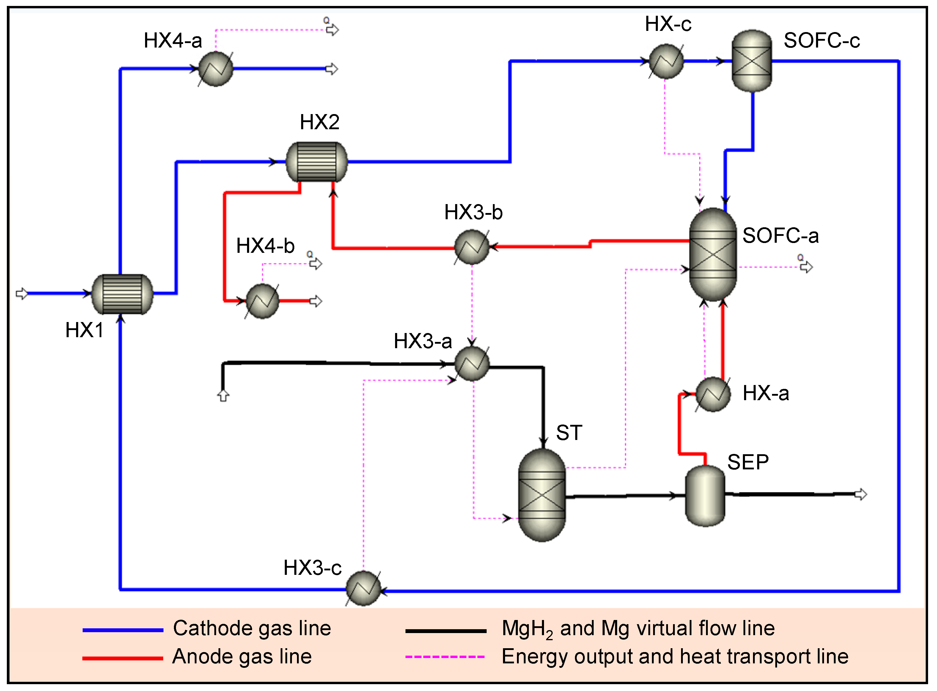
2.1. Simulation of MgH2-SOFC

Figure 1 shows a schematic of the proposed system based on our idea [6]. Heat management was simulated using AspenPlus software [27,28]. All the required heat for MgH2 dehydrogenation comes from the waste heat of the SOFC module. Our initial calculation result was first presented in our previous work [29], and the model used for calculation has been applied in the numerical calculation by Rango et al. [2] as independent research. The detailed parameters used for the calculation are shown in the supporting information. In this work, hydrogen output from MgH2 storage is fixed at 1 MPa at a fixed temperature of 643 K. The dehydrogenation rate of storage is controlled to maintain a stationary SOFC power system. In Figure 1, the storage domains are connected by virtual material flow lines to control and simulate the dehydrogenation rate from the storage. The operating conditions are shown in Table S1. Figure 2 shows the heat flow for the design in Figure 1. Descriptions of each item shown in Figure 2 are given in Table S2.
In this work, a three-dimensional steady-state single SOFC (4 cm × 4 cm) module model was developed to predict cell performance. This model considers electrochemical kinetics with mass and energy balance of gas, energy balance of solid, chemical species conservation, and electrical kinetics. The physics used for modeling these SOFCs are popular in CFD analysis, and have been proposed previously in the literature [30,31]. Complete fuel utilization for electricity production is achieved by recirculating unused fuel, with a fuel utilization factor of 30% for each pass through the SOFC. In this system, the amount of waste heat produced by ohmic and resistive activation losses in the cell is controlled by loading current, in order to supply the storage without excess heat production. The current-voltage behavior (polarization curve) is shown in Figure S1, obtained by numerical simulation of this SOFC model, which shows very similar characteristics with others’ computational and experiential results [32,33,34,35]. This confirms the validity of our calculation model.
Counter flow heat exchangers are used for heat transfer from heated off-gas (exhaust from SOFC) to unheated gas. Both anode and cathode off-gas heat are used to maintain the H2 storage tank at operating temperature using a heat exchanger “HX-3”. In all heat exchangers, the temperature of exhaust gas at the outlet side is ideally controlled so that it is equal to the temperature of all gas at the inlet side. In this work, hydrogen is produced at 1 kmol/h from MgH2 storage. In steady state, the temperature of the storage tank is maintained at operating temperature by supplying waste heat from the SOFC, as mentioned above, to compensate for the endothermic reaction of MgH2 dehydrogenation. The produced hydrogen is then heated to the SOFC operating temperature using HX-a. The temperature of the supplied air, with a feed rate of 3 kmol/h, is heated to the SOFC operating temperature using three heat exchangers (HX-1, HX-2, HX-c).

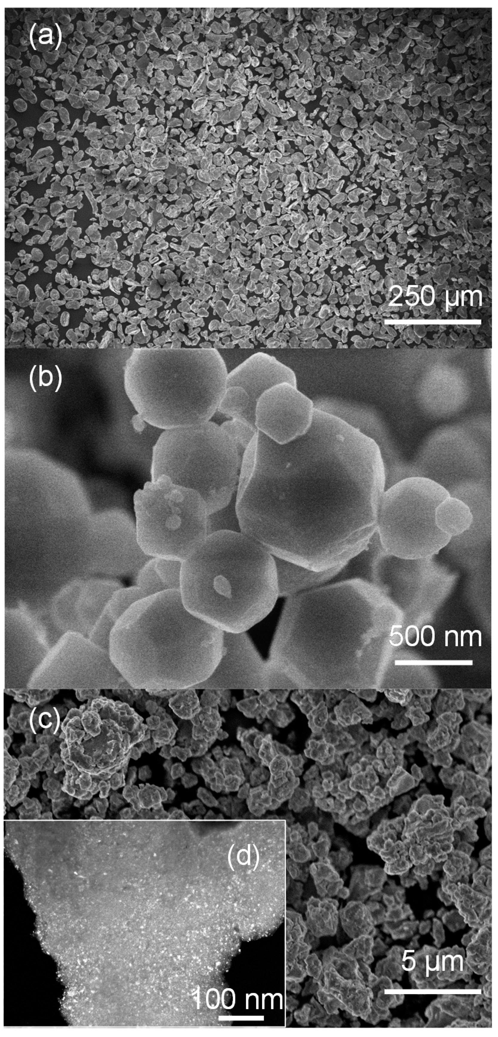
2.2. Experimental Details of Material Development

The Mg-based samples in this study include 325 mesh Mg powder sample (purity 99.8% from Alfa Aesar), Mg nanoparticles synthesized by hydrogen plasma metal reaction [25,36], and the Mg50Co50 alloy with body-centered cubic (bcc) structure, synthesized by the ball-milling method using a Fritsch P5 planetary ball mill for 100 h [26]. The author has applied these nano-processing techniques extensively in previous research for development of Mg-based materials [1]. The structure and phase information of the samples were obtained by X-ray diffraction measurements using monochromatic Cu Kα radiation. The size and morphology information were obtained by observation using scanning electron microscopy (SEM). The examination of morphology in the dark field was carried out by transmission electron microscopy (TEM) using JEOL JEM-2000FX. The hydrogen absorption properties were measured on a Sietvert-type measurement system. The thermal conductivity of the pressed pellet samples (325 mesh Mg, Mg nanoparticles and Mg50Co50 alloy) were studied on a Netzsch LFA-457 machine [24].

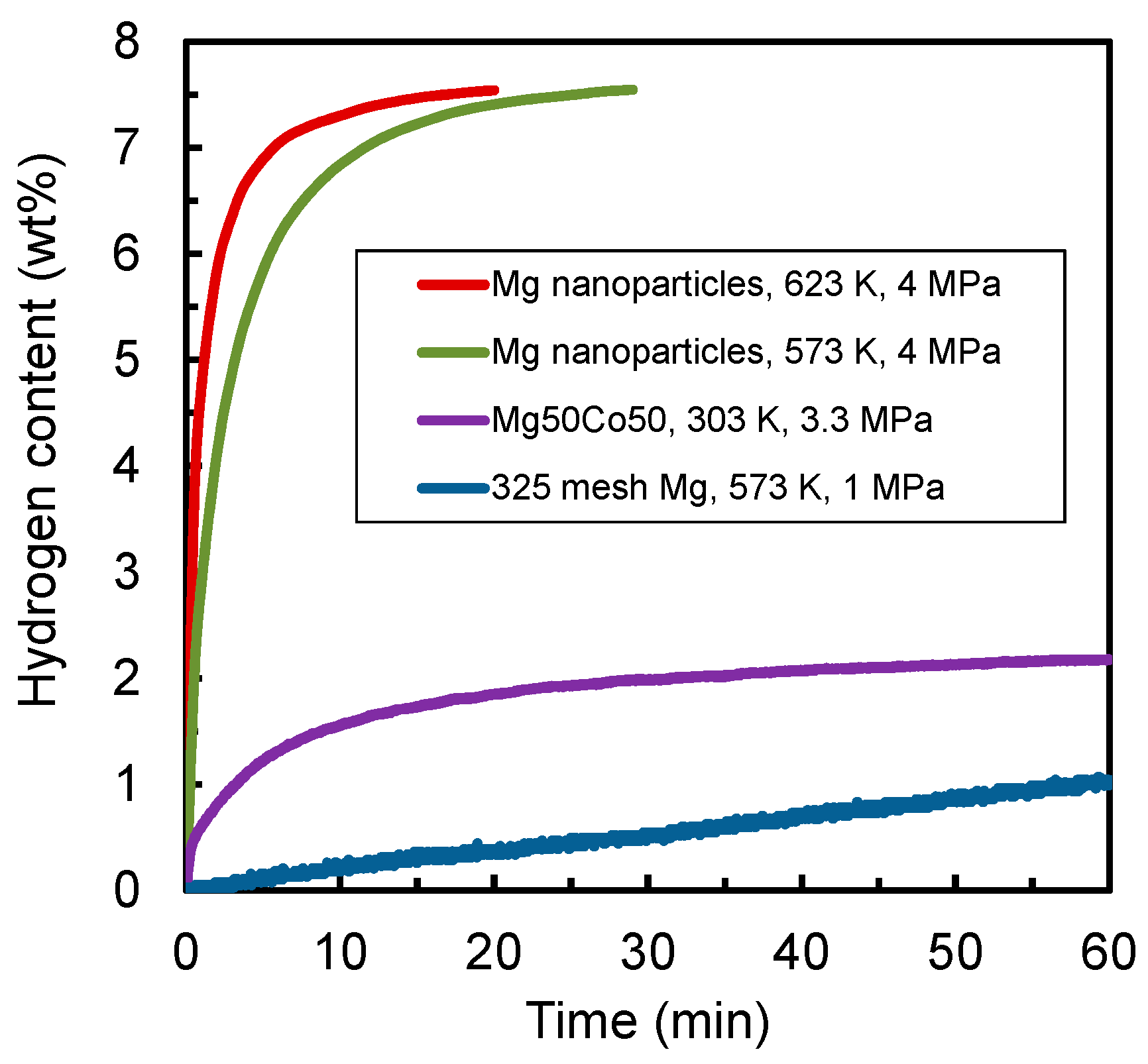
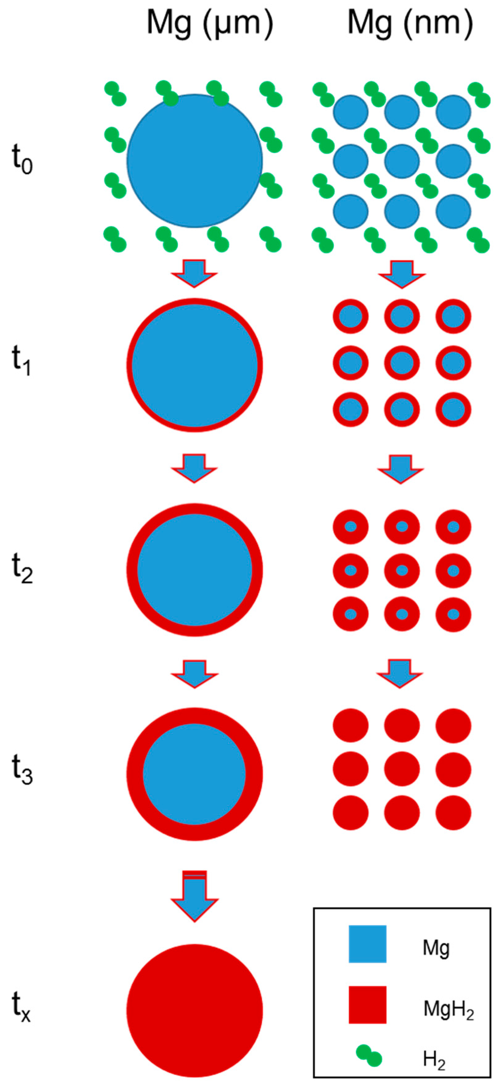
3. Results and Discussion

Tables S3–S5 show the required and available waste heats from the SOFC. All heat transfer is assumed to be completed without heat loss to the surroundings. In Tables S3 and S4, the amount of required heat to maintain operation temperature is larger than that of available heat recovered by heat transfer from off-gases. To make up for this shortage, heat generated by ohmic and resistive activation losses in the SOFC are used. In Table S5, the total heat generated and consumed by the system is reported. An excess of ~9 kW of heat is recoverable from the system for use in applications such as hot water heating. In Table 1 and Figure S2, available electrical power output, heat recovery, and heat consumed by the system are shown as a fraction of the total energy output of the SOFC system. In the present work, c in Table 2. It should be noted that the operating conditions are controlled so as to output electrical power in preference to heat production, and the present work assumes no heat loss to the surroundings, complete transfer of heat among inlet and outlet gases in the heat exchangers, and complete fuel utilization (although these factors are considered in some other studies, listed in Table 2).
From the XRD pattern in Figure 3a, we can see that the 325 mesh Mg sample (purity > 99.8%) contains only Mg phase (JCPDS 35-0821, space group P63/mmc) and, based on the reflection peaks, there is no oxide. The Mg nanoparticle sample in Figure 3b shows a similar XRD pattern to the 325 mesh Mg powder sample. There is a small MgO diffraction peak at around 43°, with this oxide having been formed when the Mg nanoparticles were passivated with air [25]. This thin MgO layer is on the surface of the Mg nanoparticles, which may prevent the sample from undergoing further oxidization. The Mg50Co50 alloy, ball-milled for 100 h, shows a bcc structure (Figure 3c) [26]. From the XRD curve, we can see that the Mg50Co50 bcc alloy shows a dramatic broadening of the reflection peaks. This indicates a very fine microstructure with severe deformation and strain after the milling process. The average crystalline size of the bcc alloy is calculated to be 1–5 nm.
The SEM and TEM images in Figure 4 present the morphology of the Mg samples. The particles of the 325 mesh sample have an irregular shape, and their average size is around 30–60 μm (Figure 4a). The Mg nanoparticle sample has a size range from 100 to 700 nm, with a mean size of around 300 nm [1,25]. For the Mg50Co50 alloy with bcc structure, the particle size is around 1 to 3 μm (Figure 4c), and the crystallite size from the dark-field TEM is a few nm, which agrees with the result calculated by broadening the XRD reflection peaks.
Figure 5 presents the hydrogen absorption kinetics curves of several Mg-based hydrogen storage samples. For the 325 mesh Mg powders, the hydrogen absorption kinetics at 573 K under hydrogen pressure of 1 MPa is very poor. The hydrogen capacity after a one-hour absorption process is only ca. 1 wt %, while the theoretical hydrogen capacity of Mg is 7.7 wt % for MgH2. At a temperature of 573 K, the equilibrium pressure of desorption of MgH2 to Mg phase is far below 1 MPa, which means 1 MPa initial pressure should not significantly affect hydrogen capacity [24,42]. It should be remembered that, before the hydrogen absorption of 325 mesh Mg, the sample was heat treated at 673 K; otherwise, it would not be able to absorb hydrogen [43,44]. The hydrogen absorption kinetics of the Mg50Co50 bcc alloy was conducted at 303 K, since this kind of metastable sample is able to absorb hydrogen at very low temperature due to its bcc structure and very fine microstructures (with particle sizes of a few μm and crystallite sizes of a few nm) [26]. The Mg50Co50 bcc alloy absorbs hydrogen at 303 K under a hydrogen pressure of 3.3 MPa with a capacity of 2.17 wt % in one hour. Although this bcc alloy shows quite good kinetics at very low temperature, its hydrogen capacity is limited, which hampers its wide application as a stationary storage material. The best hydrogen absorption properties are shown in the Mg nanoparticle sample. After one hydrogen absorption cycle, the dehydrogenated Mg nanoparticles may absorb hydrogen at a very fast speed. It can absorb hydrogen with a capacity of 7.54 wt % in 29 min at 573 K, and with a capacity of 7.54 wt % in 20 min at 623 K. In fact, most of the hydrogen is absorbed in the first 5 min. The measurement temperatures of 573 and 623 K are in the working temperature range of the MgH2-SOFC combined system concept. This demonstrates the superior hydrogen absorption kinetics and capacity of the Mg nanoparticle sample synthesized by the hydrogen plasma metal reaction method [1,42]. The mechanism for downsizing on the hydrogen absorption kinetics in Mg-based nanomaterials is illustrated in Figure 6. The hydrogen absorption process is one step in forming a MgH2 layer based on the reaction between Mg and hydrogen on the surface of Mg particles. The significant kinetics difference between the Mg nanoparticles and the 325 mesh Mg is because the Mg nanomaterials show a large surface area and a small particle/grain size [6,25,45], meaning that Mg nanomaterials have a much greater contact area for the hydrogen reaction, and a much shorter diffusion distance for hydrogen diffusion during the hydrogen absorption reaction [1,6,46,47]. For real storage application, both absorption and desorption properties, including the hydrogen capacity and kinetics, are essential for hydrogen intake and subsequent supply to the SOFC component. The desorption properties and the cycle ability of the Mg-based nanoparticles by hydrogen plasma metal reaction were proved to be good at temperature ranges of 623–673 K, according to our previous investigation [25,48].
Table 3 presents the hydrogen capacity, absorption kinetics and thermal conductivity of different Mg-based materials, with their thermal conductivity being calculated from thermal diffusivity and heat capacity measurements by the laser flash technique [24]. Thermal conductivity is important, because during the hydrogen absorption and desorption of Mg samples, a large amount of heat is involved, and this heat needs to be absorbed or taken away in a sufficiently short time, otherwise the absorption and desorption reactions may be terminated [4,49,50]. From Table 3, we can see that the 325 mesh Mg sample shows a moderate thermal conductivity of 10.42 W/(m·K) compared with other samples. However, its absorption kinetics is very poor. The Mg50Co50 bcc alloy sample shows very good kinetics at near room temperature; however, its hydrogen capacity and thermal conductivity (only 0.43 W/(m·K)) are very poor. The Mg nanoparticle sample with a particle size of around 300 nm shows superior absorption kinetics and an acceptable thermal conductivity of 4.99 W/(m·K). Its theoretical hydrogen capacity of 7.7 wt % can generally be achieved at 573–623 K in less than 30 min. This demonstrates that Mg nanoparticles by hydrogen plasma metal reaction can be promising materials for use in this MgH2-SOFC stationary energy storage system.

4. Conclusions

In this work, a heat balance simulation of the hydrogen-heat coupled MgH2-SOFC combined system was demonstrated based on our original design. It was shown that the combined system in this work has electricity conversion efficiencies (68.6% LHV of total energy) rivaling other typical SOFC combined heat and power systems (though in the present work, ideal conditions are assumed). The heat balance simulation shows that it is feasible to operate the SOFC-MgH2 storage unit as a stationary power system. For the material development for this MgH2-SOFC combined system, through evaluation of the hydrogen absorption kinetics, capacity and thermal conductivity, Mg nanoparticles by hydrogen plasma metal reaction show good hydrogen absorption kinetics and high hydrogen capacity, as well as proper thermal conductivity, which demonstrates that these Mg nanoparticle samples may be promising materials for the simulated MgH2-SOFC energy system design. This work may shed light on a new energy conversion and utilization technology based on the MgH2-SOFC combined system.

Supplementary Materials

The following are available online at www.mdpi.com/1996-1073/10/11/1767/s1, Figure S1: SOFC polarization curves. The solid and dashed lines correspond to the left and right axes, respectively, Figure S2: Available electrical power output and heat recovery from SOFC and MgH2 storage system, Table S1: Operating conditions of MgH2 storage and SOFC module, Table S2: Module domains and their functions, Table S3: The required heat to maintain steady-state operating conditions, Table S4: The available heat from waste heat of off-gas. Table S5: Heat balance of the MgH2 storage and SOFC module.

Acknowledgments

This work was partially supported by Macao Science and Technology Development Fund (FDCT project No. 118/2016/A3) and the SRG2016-00088-FST at University of Macau, China, and previously the WPI-I2CNER Program at Kyushu University, Japan. Tachikawa, Bishop and S. Liu are acknowledged for some technical contributions and discussion.

Conflicts of Interest

The authors declare no conflict of interest.

References

  1. Shao, H.; Xin, G.; Zheng, J.; Li, X.; Akiba, E. Nanotechnology in mg-based materials for hydrogen storage. Nano Energy 2012, 1, 590–601. [Google Scholar] [CrossRef]
  2. Delhomme, B.; Lanzini, A.; Ortigoza-Villalba, G.A.; Nachev, S.; de Rango, P.; Santarelli, M.; Marty, P.; Leone, P. Coupling and thermal integration of a solid oxide fuel cell with a magnesium hydride tank. Int. J. Hydrog. Energy 2013, 38, 4740–4747. [Google Scholar] [CrossRef]
  3. Doyle, T.S.; Dehouche, Z.; Stankouic, S. Decentralized power and heat derived from an eco-innovative integrated gasification fuel cell combined cycle fuelled by waste. Int. J. Hydrog. Energy 2015, 40, 9013–9025. [Google Scholar] [CrossRef]
  4. Gkanas, E.I.; Makridis, S.S. Effective thermal management of a cylindrical MgH2 tank including thermal coupling with an operating SOFC and the usage of extended surfaces during the dehydrogenation process. Int. J. Hydrog. Energy 2016, 41, 5693–5708. [Google Scholar] [CrossRef]
  5. Yiotis, A.G.; Kainourgiakis, M.E.; Kosmidis, L.I.; Charalambopoulou, G.C.; Stubos, A.K. Thermal coupling potential of solid oxide fuel cells with metal hydride tanks: Thermodynamic and design considerations towards integrated systems. J. Power Sources 2014, 269, 440–450. [Google Scholar] [CrossRef]
  6. Shao, H.; He, L.; Lin, H.; Li, H.-W. Progress and trends in mg-based materials for energy-storage research: A review. Energy Technol. 2017. [Google Scholar] [CrossRef]
  7. Lithium-Ion Battery. Available online: http://en.Wikipedia.Org/wiki/lithium-ion_battery (accessed on 4 July 2017).
  8. Mahato, N.; Banerjee, A.; Gupta, A.; Omar, S.; Balani, K. Progress in material selection for solid oxide fuel cell technology: A review. Prog. Mater Sci. 2015, 72, 141–337. [Google Scholar] [CrossRef]
  9. Bhattacharyya, D.; Rengaswamy, R. A review of solid oxide fuel cell (SOFC) dynamic models. Ind. Eng. Chem. Res. 2009, 48, 6068–6086. [Google Scholar] [CrossRef]
  10. Malzbender, J.; Steinbrech, R.W.; Singheiser, L. A review of advanced techniques for characterising SOFC behaviour. Fuel Cells 2009, 9, 785–793. [Google Scholar] [CrossRef]
  11. Patakangas, J.; Ma, Y.; Jing, Y.F.; Lund, P. Review and analysis of characterization methods and ionic conductivities for low-temperature solid oxide fuel cells (LT-SOFC). J. Power Sources 2014, 263, 315–331. [Google Scholar] [CrossRef]
  12. Perng, S.W.; Chen, C.R. Numerical investigation of anode thickness on the performance and heat/mass transport phenomenon for an anode-supported SOFC button cell. J. Nanomater. 2015, 2015, 172876. [Google Scholar] [CrossRef]
  13. Cimenti, M.; Hill, J.M. Direct utilization of liquid fuels in SOFC for portable applications: Challenges for the selection of alternative anodes. Energies 2009, 2, 377–410. [Google Scholar] [CrossRef]
  14. Nguyen, X.V.; Chang, C.T.; Jung, G.B.; Chan, S.H.; Huang, W.C.W.; Hsiao, K.J.; Lee, W.T.; Chang, S.W.; Kao, I.C. Effect of sintering temperature and applied load on anode-supported electrodes for SOFC application. Energies 2016, 9, 701. [Google Scholar] [CrossRef]
  15. Rabbani, A.; Rokni, M. Modeling and analysis of transport processes and efficiency of combined SOFC and pemfc systems. Energies 2014, 7, 5502–5522. [Google Scholar] [CrossRef] [Green Version]
  16. JXTG Company Website. Available online: http://www.Noe.Jx-group.Co.Jp (accessed on 4 July 2017).
  17. Powell, M.; Meinhardt, K.; Sprenkle, V.; Chick, L.; McVay, G. Demonstration of a highly efficient solid oxide fuel cell power system using adiabatic steam reforming and anode gas recirculation. J. Power Sources 2012, 205, 377–384. [Google Scholar] [CrossRef]
  18. Satyapal, S.; Petrovic, J.; Read, C.; Thomas, G.; Ordaz, G. The u.S. Department of energy’s national hydrogen storage project: Progress towards meeting hydrogen-powered vehicle requirements. Catal. Today 2007, 120, 246–256. [Google Scholar] [CrossRef]
  19. Nielsen, T.K.; Manickam, K.; Hirscher, M.; Besenbacher, F.; Jensen, T.R. Confinement of MgH2 nanoclusters within nanoporous aerogel scaffold materials. ACS Nano 2009, 3, 3521–3528. [Google Scholar] [CrossRef] [PubMed]
  20. Ruminski, A.M.; Bardhan, R.; Brand, A.; Aloni, S.; Urban, J.J. Synergistic enhancement of hydrogen storage and air stability via mg nanocrystal-polymer interfacial interactions. Energy Environ. Sci. 2013, 6, 3267–3271. [Google Scholar] [CrossRef]
  21. Cui, J.; Wang, H.; Liu, J.; Ouyang, L.; Zhang, Q.; Sun, D.; Yao, X.; Zhu, M. Remarkable enhancement in dehydrogenation of MgH2 by a nano-coating of multi-valence ti-based catalysts. J. Mater. Chem. A 2013, 1, 5603–5611. [Google Scholar] [CrossRef]
  22. Lu, J.; Choi, Y.J.; Fang, Z.Z.; Sohn, H.Y.; Ronnebro, E. Hydrogen storage properties of nanosized MgH2–0.1TiH2 prepared by ultrahigh-energy-high-pressure milling. J. Am. Chem. Soc. 2009, 131, 15843–15852. [Google Scholar] [PubMed]
  23. Anastasopol, A.; Pfeiffer, T.V.; Middelkoop, J.; Lafont, U.; Canales-Perez, R.J.; Schmidt-Ott, A.; Mulder, F.M.; Eijt, S.W.H. Reduced enthalpy of metal hydride formation for Mg–Ti nanocomposites produced by spark discharge generation. J. Am. Chem. Soc. 2013, 135, 7891–7900. [Google Scholar] [CrossRef] [PubMed]
  24. Shao, H.Y.; Ma, W.G.; Kohno, M.; Takata, Y.; Xin, G.B.; Fujikawa, S.; Fujino, S.; Bishop, S.; Li, X.G. Hydrogen storage and thermal conductivity properties of Mg-based materials with different structures. Int. J. Hydrog. Energy 2014, 39, 9893–9898. [Google Scholar] [CrossRef]
  25. Shao, H.; Wang, Y.; Xu, H.; Li, X. Hydrogen storage properties of magnesium ultrafine particles prepared by hydrogen plasma-metal reaction. Mater. Sci. Eng. B 2004, 110, 221–226. [Google Scholar] [CrossRef]
  26. Shao, H.; Asano, K.; Enoki, H.; Akiba, E. Fabrication, hydrogen storage properties and mechanistic study of nanostructured Mg50Co50 body-centered cubic alloy. Scr. Mater. 2009, 60, 818–821. [Google Scholar] [CrossRef]
  27. Cadoret, L.; Yu, C.C.; Huang, H.P.; Lee, M.J. Effects of physical properties estimation on process design: A case study using aspenplus. Asia-Pac. J. Chem. Eng. 2009, 4, 729–734. [Google Scholar] [CrossRef]
  28. Zhang, W.; Croiset, E.; Douglas, P.L.; Fowler, M.W.; Entchev, E. Simulation of a tubular solid oxide fuel cell stack using AspenPlusTM unit operation models. Energy Convers. Manag. 2005, 46, 181–196. [Google Scholar] [CrossRef]
  29. Shao, H.; Akiba, E. Catalyzed nanostructured Mg-based materials for energy storage. In Proceedings of the 2nd Asian Symposium on Hydrogen Storage Materials, Jeju, South Korea, 22–25 April 2012. [Google Scholar]
  30. Iwata, M.; Hikosaka, T.; Morita, M.; Iwanari, T.; Ito, K.; Onda, K.; Esaki, Y.; Sakaki, Y.; Nagata, S. Performance analysis of planar-type unit SOFC considering current and temperature distributions. Solid State Ion. 2000, 132, 297–308. [Google Scholar] [CrossRef]
  31. Wang, Y.; Yoshiba, F.; Watanabe, T.; Weng, S. Numerical analysis of electrochemical characteristics and heat/species transport for planar porous-electrode-supported SOFC. J. Power Sources 2007, 170, 101–110. [Google Scholar] [CrossRef]
  32. Lin, Y.; Beale, S.B. Performance predictions in solid oxide fuel cells. Appl. Math. Model. 2006, 30, 1485–1496. [Google Scholar] [CrossRef]
  33. Guo, H.A.; Iqbal, G.; Kang, B.S. Effects of PH3 contaminant on solid oxide fuel cells performance and related anode surface temperature measurements. Int. J. Appl. Ceram. Technol. 2011, 8, 68–73. [Google Scholar] [CrossRef]
  34. Eveloy, V.; Karunkeyoon, W.; Rodgers, P.; Al Alili, A. Energy, exergy and economic analysis of an integrated solid oxide fuel cell—Gas turbine—Organic rankine power generation system. Int. J. Hydrog. Energy 2016, 41, 13843–13858. [Google Scholar] [CrossRef]
  35. Ferrero, D.; Lanzini, A.; Leone, P.; Santarelli, M. Reversible operation of solid oxide cells under electrolysis and fuel cell modes: Experimental study and model validation. Chem. Eng. J. 2015, 274, 143–155. [Google Scholar] [CrossRef]
  36. Shao, H.; Asano, K.; Enoki, H.; Akiba, E. Correlation study between hydrogen absorption property and lattice structure of Mg-based BCC alloys. Int. J. Hydrog. Energy 2009, 34, 2312–2318. [Google Scholar] [CrossRef]
  37. Braun, R.J.; Klein, S.A.; Reindl, D.T. Evaluation of system configurations for solid oxide fuel cell-based micro-combined heat and power generators in residential applications. J. Power Sources 2006, 158, 1290–1305. [Google Scholar] [CrossRef]
  38. Rokni, M. Plant characteristics of an integrated solid oxide fuel cell cycle and a steam cycle. Energy 2010, 35, 4691–4699. [Google Scholar] [CrossRef]
  39. Bloom Energy Company Website. Available online: http://www.Bloomenergy.Com (accessed on 4 July 2017).
  40. CeresPower Company Website. Available online: http://www.Cerespower.Com (accessed on 4 July 2017).
  41. CFCL Company Website. Available online: http://www.Cfcl.Com.Au (accessed on 4 July 2017).
  42. Shao, H.; Cheng, C.; Liu, T.; Li, X. Phase, microstructure and hydrogen storage properties of mg-ni materials synthesized from metal nanoparticles. Nanotechnology 2014, 25, 135704. [Google Scholar] [CrossRef] [PubMed]
  43. Sadhasivam, T.; Kim, H.T.; Jung, S.; Roh, S.H.; Park, J.H.; Jung, H.Y. Dimensional effects of nanostructured Mg/MgH2 for hydrogen storage applications: A review. Renew. Sustain. Energy Rev. 2017, 72, 523–534. [Google Scholar] [CrossRef]
  44. Zhu, M.; Lu, Y.S.; Ouyang, L.Z.; Wang, H. Thermodynamic tuning of mg-based hydrogen storage alloys: A review. Materials 2013, 6, 4654–4674. [Google Scholar] [CrossRef] [PubMed]
  45. Wei, Z.S.; Rosa, L.; Wang, K.L.; Endo, M.; Juodkazis, S.; Ohtani, B.; Kowalska, E. Size-controlled gold nanoparticles on octahedral anatase particles as efficient plasmonic photocatalyst. Appl. Catal. B Environ. 2017, 206, 393–405. [Google Scholar] [CrossRef] [PubMed]
  46. Ouyang, L.Z.; Ma, M.L.; Huang, M.H.; Duan, R.M.; Wang, H.; Sun, L.X.; Zhu, M. Enhanced hydrogen generation properties of MgH2-based hydrides by breaking the magnesium hydroxide passivation layer. Energies 2015, 8, 4237–4252. [Google Scholar] [CrossRef]
  47. Shen, C.Q.; Aguey-Zinsou, K.F. Electrodeposited magnesium nanoparticles linking particle size to activation energy. Energies 2016, 9, 1073. [Google Scholar] [CrossRef]
  48. Shao, H.Y.; Wang, Y.T.; Li, X.G. Synthesis and properties of nanostructured Mg2Ni-based compounds. Mater. Sci. Forum 2005, 475–479, 2445–2448. [Google Scholar] [CrossRef]
  49. Bhouri, M.; Burger, I. Numerical investigation of H2 absorption in an adiabatic high-temperature metal hydride reactor based on thermochemical heat storage: MgH2 and Mg(OH)2 as reference materials. Int. J. Hydrog. Energy 2017, 42, 16632–16644. [Google Scholar] [CrossRef]
  50. Shen, D.; Zhao, C.Y. Thermal analysis of exothermic process in a magnesium hydride reactor with porous metals. Chem. Eng. Sci. 2013, 98, 273–281. [Google Scholar] [CrossRef]
Figure 1. Schematic of a process model for the MgH2-SOFC storage power system.
Energies 10 01767 g001
Figure 2. Detailed design of MgH2 and SOFC combined system used for modeling.
Energies 10 01767 g002
Figure 3. XRD curves of (a) 325 mesh Mg, (b) Mg nanoparticle sample, and (c) the milled Mg50Co50 alloy with bcc structure.
Energies 10 01767 g003
Figure 4. SEM images of (a) 325 mesh Mg, (b) Mg nanoparticle sample, and (c) the milled Mg50Co50 alloy with bcc structure. (d) Dark-field TEM image of the Mg50Co50 alloy.
Energies 10 01767 g004
Figure 5. Hydrogen absorption curves of different Mg-based samples (325 mesh Mg powers, Mg nanoparticles and the Mg50Co50 bcc alloy) in various conditions.
Energies 10 01767 g005
Figure 6. A schematic showing effect of nanosizing on absorption kinetics in hydrogen storage materials.
Energies 10 01767 g006
Table 1. Available electrical power output and heat recovery from SOFC and MgH2 storage system.
ItemQ (W)Fraction of Total Energy Generated (%)
Total energy generated by SOFC68,970100
Necessary heat to sustain operation21,63331.4
Remaining energy (electrical power output)47,33768.6
Available heat recovery923713.4
Available electrical power output + heat recovery56,57482.0
Total energy generated by SOFC68,970100
Table 2. SOFC system efficiency compared with data from references.
Electricity GenerationHeat RecoverySystem ConfigurationSource
68.6% LHV13.4% LHVSOFC + MgH2 storage unitThis study *
56.6% LHV-SOFC + gas recirculation unitPowell et al. [17]
45% LHV43% LHVSOFC + micro CHP unitBraun et al. [37]
51% LHV71% LHVSOFC + steam turbine combinedRokni [38]
42% LHV45% LHVSOFC + Heat recovery unitENE-FARM [16]
50% LHV-SOFC electrical power generationBloom Energy [39]
40–55% LHV40% LHV1 kW to MW CHP systemCeres Power [40]
60% LHV29% LHVSmall scale (1.5 kW) CHP systemCeramic Fuel Cells [41]
* Assuming no heat loss to the surroundings, complete transfer of heat among inlet and outlet gases in the heat exchangers, and complete fuel utilization.
Table 3. Hydrogen storage capacity, kinetics and thermal conductivity properties of Mg-based hydrogen storage materials.
SampleHydrogen Capacity (wt %)Hydrogen Absorption KineticsThermal Conductivity (W/(m·K))
325 mesh Mg7.7poor10.42
Mg nanoparticles7.7good4.985
Mg50Co50 bcc alloy2–3superior0.432

