Abstract
As a promising technology to improve shale gas (SG) recovery and CO2 storage capacity, the multi-well pads (MWPs) scheme has gained more and more attention. The semi-analytical pressure-buildup method has been used to estimate CO2 storage capacity. It focuses on single multi-fractured horizontal wells (SMFHWs) and does not consider multi-well pressure interference (MWPI) induced by the MWPs scheme. This severely limits the application of this method as incidences of multi-well pressure interference have been widely reported. This paper proposed a new methodology to optimize the injection strategy of the MWPs scheme and maximize CO2 storage capacity. The new method implements numerical discretization, the superposition theory, Gauss elimination, and the Stehfest numerical algorithm to obtain pressure-buildup solutions for the MWPs scheme. The solution by the new method was validated with numerical simulation and pressure-buildup curves were generated to identify MWPI. Using the new method, we observed that the fracture number and fracture half-length have a positive influence on CO2 storage capacity. Both can be approximately related to the CO2 storage capacity by a linear correlation. For a given injection pressure, there is an optimal fracture number; the bigger the limited injection pressure, the smaller the optimal fracture number. Stress sensitivity has positive influences on CO2 storage capacity, thus extending the injection period would improve CO2 storage capacity. This work gains some insights into the CO2 storage capacity of the MWPs scheme in depleted SG reservoirs, and provides considerable guidance on injection strategies to maximize CO2 storage capacity in depleted SG reservoirs.
1. Introduction
Greenhouse gas control has been a focus of research attention due to climate change induced by the emission of greenhouse gases such as carbon dioxide [1,2]. Geological sequestration is considered one of the most effective ways to mitigate CO2 emissions. This knowledge is based on capturing CO2 from emission sources and injecting it into deep geological structures. There are several sequential options for sequestrating CO2 in geological sinks, including injecting CO2 into deep saline aquifers, mature oil and gas reservoirs for the purpose of both of sequestration and production enhancement, injecting CO2 into depleted oil and gas reservoirs, and injecting CO2 into unconventional coal seams and shale layers [3,4] to enhance gas recovery and CO2 storage capacity simultaneously, which has been a central topic for many years.
The estimation methods of CO2 storage capacity in shale formations can be classified into four categories: (1) volume-based calculation methods; (2) production-based calculation methods; (3) numerical simulation methods; and (4) semi-analytical model methods. The volume-based calculation method is easy to apply. Busch et al.; Kang et al and Tian et al. [5,6,7,8,9] experimentally measured the storage volume of CO2 in shale samples from Barnett Shale, TX, USA, and Sichuan, China. In return, the CO2 storage capacity can be easily calculated by incorporating the whole volume of shale formation. The production-based method was introduced by Tao et al. [10] to evaluate the CO2 sequestration capacity of the Marcellus Shale. They estimated the CO2 storage capacity based on historical and projected shale gas production data. The production-based calculation method is attractive due to the rapid process. Unfortunately, its accuracy may decrease due to poor-quality production data. Numerical simulation methods were established to evaluate the storage capacity of CO2 injection [11], which can also be used to simulate CO2 flow behavior in shale. However, this method requires grid discretion, which is time-consuming in a field-scale application [12,13]. Edwards et al. [14] established a two-component (CO2 and CH4) model of gas flow in a shale gas formation including adsorption effects. They used the method to evaluate the CO2 storage capacity of Barnet shale. Borrowing some thoughts from the literature [15,16,17,18,19,20], Chen et al. [21] and Xiao et al. [22] establish a semi-analytical model based on transient pressure buildup of an injection well for CO2 storage in depleted shale gas reservoirs.
Developing unconventional shale resources has challenged conventional methodologies and engineers for the past few decades. Fortunately, advancements in technology and new analysis methods have allowed SMFHWs to become more economical. After the abandonment of a depleted shale gas reservoir, SMFHWs could be a feasible path to transporting CO2 into a shale play. Recently, the MWPs scheme has been a center of attention as a promising improved shale gas (SG) recovery and economical CO2 storage technology [23,24]. Micro-seismic fracturing mapping showed hydraulic fractures extending between wells (Figure 1), gaining the existence of MWPI [25,26]. On the one hand, compared with SMFHWs, the MWPs scheme can provide a more high-conductivity path to transport CO2 into an underground shale play, and thereby seemingly could gain much more CO2 storage capacity [27]. On the other hand, MWPI can also stimulate injection pressure, which in turn sharply decreases the CO2 injection capacity of MWPs [23]. This outstanding contradiction urges us to determine whether multi-wells should be injected simultaneously or sequentially and how to inject them under different injection rates. As a result, this technology strongly challenges the previously effective methodology for estimating CO2 storage capacity using the semi-analytical pressure-buildup method mentioned above, which focuses on SMFHWs without pressure MWPI [21,22]. Therefore, finding a methodology to optimize the injection strategy of the MWPs scheme to maximize CO2 storage capacity is a necessity.
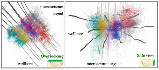
Figure 1.
Micro-seismic imaging of MWPs shows fractures extending between wells.
Our objectives were to determine the maximum CO2 storage capacity of the MWPs scheme in depleted shale gas reservoir by addressing the following questions:
- What kinds of pressure buildup can we obtain for the MWPs scheme? What is the difference between the MWPs scheme and SMWHF?
- How can we determine the occurrence of MWPI in the MWPs scheme when we inject CO2?
- How can we optimize the injection strategy of the MWPs scheme for maximizing CO2 storage capacity with MWPI?
To answer the questions outlined above, we propose a methodology consisting of four issues that should be solved sequentially and systematically:
- Development of an efficient semi-analytical pressure-buildup model for the MWPs scheme;
- Based on the proposed semi-analytical pressure-transient model, the CO2 storage capacity of the MWPs scheme is calculated;
- Based on the proposed semi-analytical pressure-transient model, we identify MWPI using pressure-buildup curves;
- Based on the proposed semi-analytical pressure-transient model and the identification of MWPI, we optimize the CO2 multi-wells injection strategy (whether multi-wells have CO2 injected simultaneously or sequentially).
In our Section 2, we mainly focus on the first issues; the remaining three issues and a case study will be explained in our Section 3. To facilitate methodology development, this paper is organized as follows. First, we describe the conceptual models of SG formation and MWPs scheme. Second, CO2 seepage models of shale gas reservoir and HFs are sequentially established and then dynamically coupled. After that, by numerical discretization, superposition theory, Gauss elimination, and Stehfest numerical algorithm, pressure-buildup solutions of MWPs scheme are obtained. Then, to validate our model, numerical simulation is utilized with CMG-GEM module (2015.10.5641.22410, Computer Modelling Group Ltd., Calgary, AB, Canada). Finally, sensitivity analysis is also conducted.
Described below are the attributes of our methodology framework, including details of the development of semi-analytical pressure-buildup model, calculation of CO2 storage capacity, sensitivity analysis, discussion of results, and related insights. More information on model derivation is provided in the Appendix.
2. Development of Pressure-Buildup Model for MWPs Scheme
Single-phase CO2 gas (regardless of phase change, such as supercritical CO2) was used for the development of a semi-analytical pressure-buildup model. The pressure-buildup response of the MWPs scheme was a result of CO2 flow in a shale gas (SG) system and stimulated HFs system. CO2 flows from a wellbore into the HFs system, then through the HFs system into a shale play. In this paper, we assumed no frictional pressure loss inside the wellbore, thus, we envisaged two distinct flow regimes governed by different physics: SG reservoir flow and HFs system flow. In the following sections, we first describe a conceptual model of the SG system and MWPs scheme used and then mathematically model these two flow processes. Finally, the SG flow model and fracture system flow model are coupled dynamically.
2.1. Description of Conceptual Model
2.1.1. Multi-Well Pad Production (MWPs) Scheme
Figure 2 illustrates the placement of MWP schemes in a SG reservoir. Each MWP scheme has one shared production platform and can contain several SMFHWs. Figure 2a illustrates the micro-seismic surveillance within an MWP scheme. Based on the micro-seismic experiment, we can clearly observe that the distribution of HFs can be classified into four types (see Figure 2b) [23].
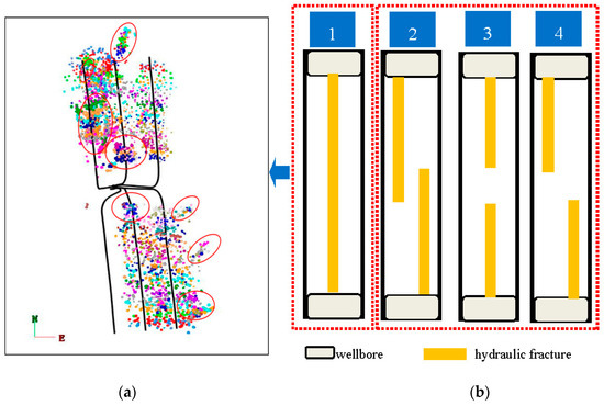
Figure 2.
The schematic illustration of a MWP scheme in a shale gas reservoir: (a) Microseismic monitoring map; (b) The distribution of HFs.
2.1.2. SG Formation Model
The conceptual model of a SG formation can be illustrated as in Figure 3. The reservoir, within infinite boundary, is treated as 2D due to the fact that the reservoir thickness is far smaller than its radius. A SG reservoir is assumed to be isotropic, including a natural fracture system and a matrix system, and bounded by upper and lower impermeable strata. Three media exist in the SG reservoir: (1) the lowest permeable shale matrix distributed in the reservoir; (2) the moderate permeable NFs in the reservoir; and (3) the highest permeable HFs, perpendicular to the wellbore.
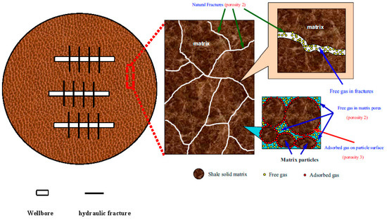
Figure 3.
Conceptual model for a typical shale gas reservoir.
To conveniently describe our methodology, we chose three SMFHWs to be our research objective. However, our methodology could be easily extended to a MWPs scheme with more than three wells. Three SMFHWs were produced at constant gas rates q1, q2, and q3. CO2 in HFs flows into a shale play at flow-rate strength qf. To conveniently derive a pressure-buildup model, some other assumptions were as follows:
- Three horizontal wells were intercepted by several symmetric HFs. The fractures were assumed to fully penetrate the SG reservoir.
- A SG reservoir has uniform thickness h. Depleted pressure and temperature are Pd and T.
- CO2 seepage within a natural fracture system obeyed Darcy’s law. The shape of the matrix was simplified as a sphere and CO2 flow within the matrix was assumed to obey Fick’s first law. The natural fracture system was stress-dependent with initial permeability kri.
- The compressibility coefficient of the slightly compressible CO2 was constant;
- The impacts of gravity and capillary pressure were neglected.
- CO2 absorption and adsorption meet the Langmuir isotherm equation.
- Wellbore storage and skin factor can be considered.
- No frictional pressure loss inside the wellbore was considered.
- Because of the lack of supercritical adsorption data, CO2 was assumed to be persistently in the gas phase during the injection, with a constant Z-factor and viscosity. CO2 leakage is assumed when CO2 is injected into a depleted SG reservoir.
2.2. Mathematical Model
2.2.1. Hydraulic Fracture Discrete
As one can see in Figure 4, the properties of hydraulic fracture for Well 1 include fracture permeability, kf1; fracture width, wf1; and fracture half-length, Lf1. The properties of hydraulic fracture for Well 2 include fracture permeability, kf2; fracture width, wf2; and fracture half-length, Lf2. The properties of hydraulic fracture for Well 3 include fracture permeability, kf3; fracture width, wf3; and fracture half-length, Lf3. The distances between two of these three wells were Lw12 and Lw32. The fracture distance between two of these three wells was Lf12 and Lf32. To establish a mathematical model, we discretized a hydraulic fracture system of the MWPs scheme. We assumed that one hydraulic fracture of Well 1, Well 2, and Well 3 was divided into N1, N2, and N3 sub-fracture segments, respectively. The hydraulic fracture numbers of Well 1, Well 2, and Well 3 were M1, M2, and M3. The length of each fracture segment for Well 1, Well 2, and Well 3 can be presented as ∆Lf1, ∆Lf2, and ∆Lf3, respectively. After that, each sub-fracture segment was considered as an independent fracture unit, and the pressure responses caused by these fracture segments are calculated.
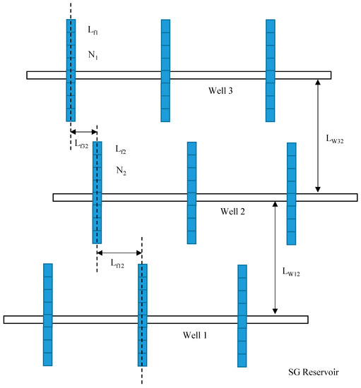
Figure 4.
Grid discretion of multi-well pad production (MWPs) scheme.
2.2.2. Model of CO2 Flow in SG Reservoir System
To develop mathematical models in a SG reservoir, the formulae of the NFs system and matrix system can be established separately and then dynamically coupled [19,20,22]. Therefore, in a Laplace domain, the dimensionless governing equations with consideration of stress sensitivity and pseudo-steady diffusion can be presented as follows (more information on dimensionless definition and model development are provided in Appendix A and Appendix B):
Dimensionless boundary conditions:
Substituting Equation (2) into Equation (1), one can get the following governing equation combining the natural fracture system and the matrix system:
Equations (3)–(5) comprise a comprehensive mathematical model in a SG reservoir coupling the NFs system and the matrix system. The typical solution of the models has been given in the literature [19,22] and is also in Appendix B. Based on the solution, by applying the principle of integration, the pressure distribution of a random position (xD, yD) caused by one fracture segment (xWD, yWD) is given by the following equation:
where:
2.2.3. Model of CO2 Flow in a HF System
As described by some previous researchers [21,28,29,30], the CO2 flow within a hydraulic fracture system was assumed to be compressible and can be described as a 1D coordinate system (Figure 5). CO2 flow within hydraulic fracture also obeys Darcy’s law. As seen in Figure 2b and Figure 5, the interaction of hydraulic fractures between two wells for the MWPs scheme can be classified into two scenarios: with direct connection and without direct connection.
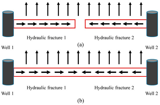
Figure 5.
Plan view of CO2 flow within HF system: (a) HFs are not connected between two wells; (b) HFs are connected between two wells.
With the definition of dimensionless variables mentioned in Appendix A, the flow equations with the dimensionless formula can be presented as follows (the model derivation can be found in Appendix C):
At initial condition,
When hydraulic fractures are not in direct connection between two wells, with the inner boundary in contact with the wellbore,
The outer boundary condition can be presented as follows because of no flow transportation at the tip of the fracture:
When hydraulic fractures are a direct connection between two wells, the two tips of hydraulic fracture separately make contact with Well 1 and Well 2, thus giving
2.3. Solution of Pressure-Buildup for MWPs Scheme
2.3.1. SG Reservoir System
Traditionally, we employed the superposition principle [31] to calculate the pressure response for SMFHWs. Similarly, we also can apply the superposition principle to the MWPs scheme. On the basis of Equation (6), we can obtain the transient pressure response at the center of each segment of the HFs system in the MWPs scheme with the superposition principle:
where
is the pressure response at the o-th fracture segment, caused by the flux of the b-th fracture segment in the a-th hydraulic fracture for Well 1; is the pressure response at the o-th fracture segment, caused by the flux of the j-th fracture segment in the i-th hydraulic fracture for Well 2; is the pressure response at the o-th fracture segment, caused by the flux of the d-th fracture segment in the c-th hydraulic fracture for Well 3.
2.3.2. Hydraulic Fracture System
In this section, we will describe the later issue about fluid transferring at the interacting point between the hydraulic fracture and the natural fracture. Due to the possible connection of the HFs system, it is a key point when dealing with the fluid transferring between those two fracture media. Zhou et al. [30] and Chen et al. [21] artificially determined the flow direction, while Jia et al. [29] employed complex star-transformation to automatically determine the flow direction. In our work, the connecting HFs system is simple (sparse hydraulic fractures), therefore we artificially specify the flow direction and solve the issue of fluid transferring between those two fracture media.
Independent Fracture Segment
Here, a semi-analytical method [21,28,30,32] is applied to solve models of fracture systems considering finite hydraulic fracture conductivity. Zeng et al. [28] proposed a semi-analytical method that divided the fracture system into several segments; each segment was solved analytically. As one can see in Figure 6, we chose the ith fracture segment to analyze the flow equation. The fluid flow rate from position to , because of the fluid supplement of segment flux qfi, increases from qci1 to qci2 along .
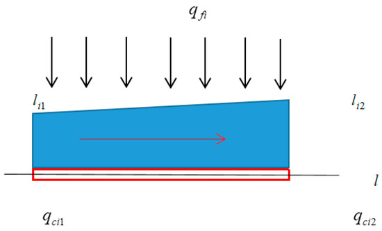
Figure 6.
Illustration of gas flow within the ith fracture segment.
We take hydraulic fracture as an example, and the solution for a natural fracture is similar. Therefore, based on Equation (7), the governing equation of the ith fracture segment can be established as:
and boundary conditions at and given by
Combining with Equations (17)–(19), and integrating with the fracture segment, we can obtain the pressure distribution within the ith fracture segment. The method proposed by Zeng et al. [28] is applied to obtain an analytical solution in this fracture segment. The solution in Laplace space for the ith fracture segment is a function of the flow rate at both sides of the fracture segment and the fluid influx from the SG reservoir:
Therefore, the pressure at the center of the ith fracture segment is
where
Connecting Fracture Segment
As illustrated in Figure 5b, if the hydraulic fractures of two wells interact with each other, we need to pay special attention to the mass balance at the connecting point. As illustrated by Zhou et al. [30] in Figure 7, due to the relatively small size of the interacting point, the fluid accumulation can be ignored and therefore the inflow should be equal to the outflow. In this work, we consider a simple fracture system, so it was suitable to determine the flow direction artificially. For the vertex, in conditions of mass conservation and pressure continuity, we can obtain
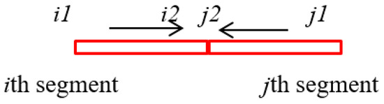
Figure 7.
Illustration of fluid transferring in connecting vertex.
2.3.3. Solution Methodology
From the proposed equations, we see that there are three unknowns, , , and , for each fracture segment. Therefore, the total number of unknowns is equal to [3(M1 × N1 + M2 × N2 + M3 × N3) + 3]. We can obtain a closed [3(M1 × N1 + M2 × N2) + 3]-order matrix with the following conditions:
Combining Equation (13) with Equation (21), the pressure at the center of fracture area is continuity:
After rewriting Equation (27) for every fracture segment of the MWPs scheme, we can obtain a (M1 × N1+ M2 × N2 + M3 × N3)-order matrix.
For two connecting fracture segments, the ith segment and (i + 1)th segment, the pressure and fluid rate of connecting point are equal to each other, namely,
For the connecting vertex, Equation (25) can describe the mass conservation of this point. At the same time, considering the boundary condition of HFs, after rewriting Equations (25) and (26) for every fracture segment, we obtain two more (M1 × N1 + M2 × N2 + M3 × N3)-equations.
Another three equations were required to form a closed matrix. Well 1, Well 2, and Well 3 produced at the constant rates of q1, q2, and q3, respectively. Here, we define three new variables, ε1, ε2, and ε3, representing the ratio between q1, q2, q3 and (q1 + q2 + q3). Namely, , , and . Therefore, the remaining three equations referring to the rate conversion of the three wells are as follows:
Finally, we can form a closed [3(M1 × N1 + M2 × N2 + M3 × N3) + 3]-order matrix. By applying Gaussian elimination and a Stehfest numerical algorithm, the pressure transient solution, , and of the mathematical model can be solved. Using the Stehfest numerical invention algorithm [33] we can obtain the solution in real space, namely by converting . One can get the bottom-hole pressure for the MWPs scheme in a SG reservoir by taking the stress sensitivity into consideration:
3. Results and Discussion
In this part, four cases are used for (1) discretization of hydraulic fractures; (2) model verification; (3) calculation of CO2 storage capacity for MWPs scheme; and (4) sensitivity analysis. The parameters of some cases are shown in Table 1. The detailed procedure can be presented as follows.

Table 1.
The basic parameters for numerical simulation.
3.1. Discretization Level of Fracture System
Due to the inappropriate discretization of HFs, early transient pressure response can be distorted by artifacts of fracture subdivision [21]. Therefore, the accuracy of our approach partially depends on the discretization level of the fracture system. The basic dimensionless parameters are as follows: ζD = 0, λ = 0.002, γ = 0.15, ω = 0.0035, CηD = 105, Lf1D = 200, Lf2D = 200, Lf3D = 200, Lw12D = 3000, Lw32D = 3000, Lf12D = 1000, Lf32D = 1000, Cf1D = 125, Cf2D = 125, and Cf3D = 125. Figure 8 shows the effects of a divided fracture number on the pressure-transient performance. In Figure 8, ψwD represents the dimensionless pseudo-pressure (DPP), dψwD/d(lntD) represents the derivative of dimensionless pseudo-pressure ψwD with respect to the natural logarithm of dimensionless time tD. As we can see, when more than 10 fracture segments, M, are divided for each hydraulic fracture, the results do not change appreciably. Therefore, each fracture is divided into 10 segments in our work, including the model validation and sensitivity analysis.
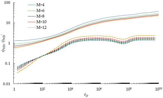
Figure 8.
Sensitivity analysis on the number of divided fracture segments.
3.2. Model Validation
Currently, semi-analytical/analytical pressure-transient models for multi-wells have not existed. Therefore, Case II is also applied for numerical validation of the MWPs scheme. Case II is modeled by a commercial simulator, CMG-2015, and the top view is shown in Figure 9. The model considers SG reservoir to be a dual-porosity system and the CMG-GEM module is selected to simulate the proposed MWPs scheme. Seen in Figure 9, one representative segment is modeled that represents one part of the reservoir volume around a hydraulic fracture. This segment contains four hydraulic fractures orthogonal to the horizontal well at 250 m fracture spacing. This is a 2D model with 55 grid cells in the x-direction, 55 grid cells in y-direction, and only one grid cell in the z-direction. The multi-porosity model and multiple interacting continua (MINC) method are applied to subdivide the matrix so that the transient diffusion in the matrix can be simulated. It is characterized as an instant-desorption model. Double Klinkenberg permeability-Logarithmically Space-Local Grid Refinement (DK-LS-LGR) technology is employed to characterize a multi-stage hydraulic fractures system. Each hydraulic fracture is represented by a 3 × 3 locally refined grid 0.025 m wide. The ROCKTAB keyword is used to indicate the stress sensitivity. Furthermore, the keywords “DIFFCBM” and “LANGMEXT” are employed to describe the mechanisms of gas diffusion and adsorption. Then, the pressure solution of Case II is calculated under a constant production rate. We assume that q1:q2:q3 = 2:3:5, and the fracture properties of the three wells are consistent. After that, the numerical solutions are compared with the semi-analytical results calculated in this paper. As we can see in Figure 10, there is a good agreement between our results and CMGs, which indicates that our model is reliable.
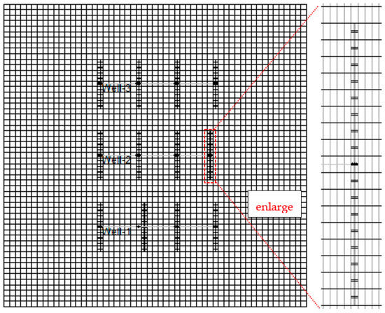
Figure 9.
Top view of the numerical model of Case II in the CMG-GEM module.
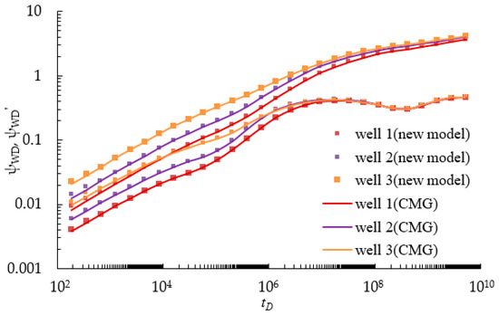
Figure 10.
Comparison of the results of our model with those of the CMG simulator.
Besides the comparison of calculation accuracy, the speed of the computations for these two models was also investigated. With the same hardware platform, the CPU times are 285.2 s and 203.5 s for the semi-analytical and fully numerical model, respectively. Compared with the simulator, the computation performance presented is not significantly improved. We suggest that this comparison for the computation performance should be a rough evaluation due to the simple fracture configuration (perpendicular to wellbore), the relatively small total length of the fracture, and the implementation (programming with MATLAB codes without optimization for our model). The improvement may be encouraged by the fracture network with complex geometry or some programming techniques.
3.3. Multi-Well Pressure Interference
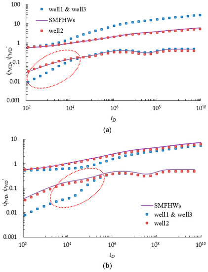
Due to the existence of MWPI, some expected flow regimes, such as fracture linear flow, fracture-formation bi-linear flow, and formation linear flow, are apparently distorted (Figure 11). The slope of type curves that characterize the linear or bi-linear flow regime is no longer equal to 0.5 or 0.25. To clearly describe the distortion of type curves, we will compare the characteristics of pressure curves without and with MWPI. We can realize this condition by shutting one well or setting the distance between two wells long enough, and therefore the MWPs scheme can be regarded as SMFHWs. In this part, we just give some proof that the MWPI is significant for the MWPs scheme, which cannot be ignored during CO2 capture and storage. Some detailed information about how to quantitatively determine the MWPI time will be described in this part.
Enhancement of the possibility of MWPI induced by the MWPs scheme can stimulate the injection pressure to rapidly reach constraint pressure, which in turn sharply decreases the CO2 injection capacity of MWPs. We also need to note that MWPI is different for different wells; as a result, different wells may reach the limited injection pressure at different times. Under this situation, part of wells will shut down, while the remaining wells will continue to inject CO2. Thus, the virtual-well theory and pressure superposition method need to be employed to solve this problem. These issues are related to the optimization of a CO2 multi-wells injection strategy about whether multi-wells inject CO2 simultaneously or sequentially, which will also be considered in our Section 2. In that part, some additional mathematical derivations will be added.
Here, to conveniently implement the calculation of CO2 storage capacity for the MWPs scheme, we make the assumption that all of the wells will shut down as long as one of them reaches the limited injection pressure.
3.4. Calculation of CO2 Storage Capacity
The main goal of our work is the calculation of the CO2 storage capacity of the MWPs scheme in a depleted SG reservoir. Similar to the calculation method proposed by Chen et al. [21], which assumed that the limited injection pressure should be set to below the lithostatic pressure (8.55 MPa) and CO2 supercritical pressure (which we set at 7.0 MPa, which is slightly lower than the supercritical pressure of 7.239 MPa).
Firstly, we specify the injection rate of each well, qi, and calculate the ratio ε1, ε2, ε3 between q1, q2, q3 and (q1 + q2 + q3). Based on the pressure transient solution in Equations (33)–(35), the pressure transient curves of the MWPs scheme can be obtained at a specific injection rate. We set a constrained injection pressure Pcon, and then calculated the dimensionless constrained injection pressure ψconD. When downhole pressure of one well reaches the dimensionless constrained pressure ψconD, we can get the dimensionless injection time tinD. Finally, we can calculate the injection time tin; therefore, the total injected CO2 volume will be:
The parameters of the depleted SG reservoir, rock, wells, and CO2 are shown in Table 1. Here, we take Figure 2b (3) as an example. Lw12 = Lw32 = 300, and Lf12 = Lf32 = 0. The calculation of the CO2 storage capacity can be undertaken via the following steps:
- (1)
- Based on a specific injection rate, the ratio ε1, ε2, ε3 between q1, q2, q3 and (q1 + q2 + q3) can be calculated as
- (2)
- Calculation of dimensionless limited injection pressure with the dimensionless parameters and constrained injection pressure Pcon:
- (3)
- Based on the pressure curve in Figure 12, Well 3 reaches limited injection pressure . Thus, dimensionless injection time can be obtained as
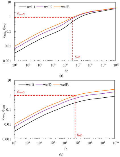 Figure 12. Illustration of pressure build-up curve (q1:q2:q3 = 1:2:3), Pcon = 7 MPa: (a) MWPs scheme, Figure 2b, Case 3; (b) SMFHWs.
 - (4)
- Based on obtained injection time tinD, total CO2 injection volume can be calculated as follows:
The MWPI induced by the MWPs scheme can stimulate injection pressure to rapidly reach constraint injection pressure. Here, we also compare the SMFHWs without considering the existing MWPI, still assuming that all wells will shut down as long as one of them reaches the limited injection pressure. Repeating the above steps, the final results can be summarized in Table 2. The SMFHWs overestimate the CO2 storage capacity, which demonstrates that MWPI has a significant influence on estimations of CO2 storage capacity.
Table 2.
Comparison between MWPs, SMFHWs, and numerical results.
3.5. Sensitivity Analysis
3.5.1. Effects of Different MWPs Schemes
The pressure build-up is partially determined by different distribution of HFs in MWPs scheme (Figure 2b). We can set some common parameters for those three wells: M1 = 3, M2 = 3, M3 = 3, ζD = 0, λ = 0.002, γ = 0.15, ω = 0.0035, CηD = 105, Lf1D = Lf2D = Lf3D = 500, Cf1D = Cf2D = Cf2D = 10. q1:q2:q3 = 1:2:3. Another four parameters, Lw12D, Lw32D, Lf12D, and Lf32D, determine the different interference types illustrated in Figure 2b, which can be mathematically described as follows:
Based on these pressure types in Figure 13 and the results in Table 3, when wells are directly connected with hydraulic fracture for MWPs scheme, the occurrence of MWPI is much earlier than in the other three kinds of MWPs schemes. In our case, when limited injection Pcon = 7 MPa, CO2 storage capacity approximately decreases by 200% from the interference type Figure 2b (3) and (4).
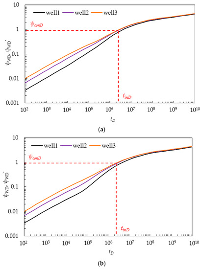
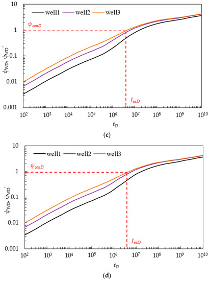
Table 3.
Comparison of different MWPs.
3.5.2. Effects of Ration of Well Rate ε1, ε2, ε3
We define a new concept of injection capacity (IC), the total injection volume of MWPs per day. IC ranges from 20 to 150 × 104 m3/d. Fracture number M1 = M2 = M3 = 2. The value of ε1:ε2:ε3 is 1:3:1, 1:1:1, and 2:1:2. We take Figure 2b (3) as an example. Lw12 = Lw32 = 200, and Lf12 = Lf32 = 0. Lf1 = Lf2 = Lf3 = 50 m. Figure 14a shows the pressure curves of wells that reach limited injection pressure. Figure 14b shows CO2 storage capacity under different injection capacity IC and values of ε1:ε2:ε3. It indicates that CO2 storage capacity will decrease with the increasing of the injection capacity (IC); moreover, the ratio of CO2 storage capacity decreases with the increasing of IC. In our case, when IC is bigger than 100 × 104 m3/d, the CO2 storage capacity remains approximately constant. This surprising result suggests that a small CO2 injection rate can CO2 storage capacity. In addition, because Well 2 is severely influenced by MWPI, CO2 storage capacity is the lowest when Well 2 has a higher injection rate. In our case, we obtain much more CO2 storage capacity when the injection rates of Well 1 and Well 3 are bigger than that of Well 2. More information about the effects of MWPI on the CO2 injection strategy will be given in our Section 2.
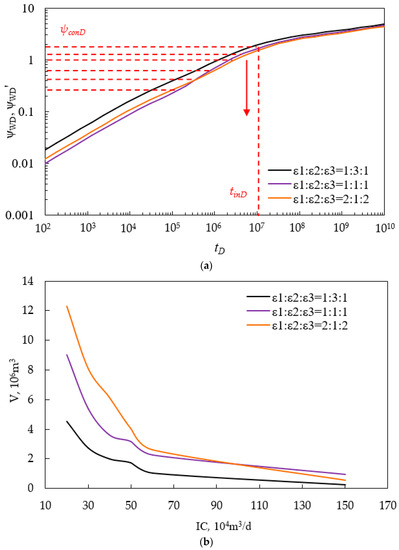
Figure 14.
(a) Comparison pressure with different IC; (b) comparison of CO2 storage capacity with different IC and ε1:ε2:ε3.
3.5.3. Effects of Hydraulic Fracture Half-Length
We take Figure 2b (4) as an example. Lw12 = Lw32 = 300, and Lf12 = Lf32 = 100. IC = 50 × 105 m3/d. Fracture number M1 = M2 = M3 = 2. ε1:ε2:ε3 = 2:1:2. Hydraulic fracture half-length Lf1 = Lf2 = Lf3 ranges from 50 to 200. Figure 15a shows the pressure curves of wells that reach limited injection pressure. Figure 15b shows the effects of hydraulic fracture half-length Lf1 = Lf2 = Lf3 on CO2 storage capacity for MWPs scheme in a depleted SG reservoir under different constrained injection pressure Pcon. It indicates that CO2 storage capacity increases with the increasing of fracture half-length; moreover, CO2 storage capacity has an approximately linear relationship with Lf. In addition, as limited injection pressure Pcon increases, CO2 storage capacity also increases; what is more, the longer the fracture half-length, the more the CO2 storage capacity increases when we set a higher limited injection pressure. This means that when a SG reservoir has bigger Pcon, longer Lf is beneficial to improve CO2 storage capacity.
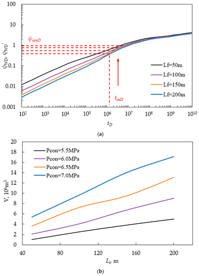
Figure 15.
(a) Comparison pressure with different fracture half-length; (b) comparison of CO2 storage capacity with different fracture half-length.
3.5.4. Effects of Hydraulic Fracture Number
We take Figure 2b (3) as an example. Lw12 = Lw32 = 300, and Lf12 = Lf32 = 0. IC = 50 × 105 m3/d. ε1:ε2:ε3 = 2:1:2. Lf1 = Lf2 = Lf3 = 50 m. Fracture number M1 = M2 = M3 ranges from 2 to 4. Figure 16a shows the pressure curves of wells that reach limited injection pressure. Figure 16b shows the effects of hydraulic fracture number M1 = M2 = M3 on CO2 storage capacity for the MWPs scheme in a depleted SG reservoir under different constrained injection pressure Pcon. It indicates that CO2 storage capacity increases with the increase in the fracture number. There is an optimal fracture number beyond which the CO2 storage capacity will not increase appreciably. The bigger the limited injection pressure Pcon, the smaller the optimal fracture number. In our case, when limited injection pressure Pcon = 7.0 MPa, the optimal fracture number is 5. Similarly, as limited injection pressure Pcon increases, the CO2 storage capacity also increases.
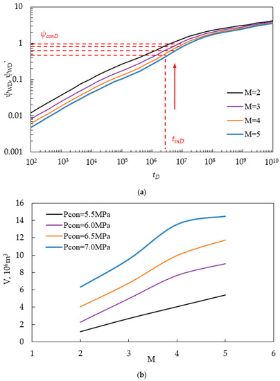
Figure 16.
(a) Comparison pressure with different fracture number; (b) comparison of CO2 storage capacity with different fracture number.
3.5.5. Effects of Stress Sensitivity
We take Figure 2b (3) as an example. Lw12 = Lw32 = 300, and Lf12 = Lf32 = 0. IC = 50 × 105 m3/d. Fracture number M1 = M2 = M3 = 2. ε1:ε2:ε3 = 2:1:2. Lf1 = Lf2 = Lf3 = 50 m. ζD ranges from 0.01 to 0.05. Figure 17a shows the pressure curves of wells that reach limited injection pressure. Figure 17b shows the effects of stress sensitivity coefficient ζD on CO2 storage capacity for the MWPs scheme in a depleted SG reservoir under different constrained injection pressure Pcon. Our results demonstrate that stress sensitivity coefficient ζD has a positive influence on CO2 storage capacity. Because stress sensitivity can increase the permeability of a SG reservoir, as ζD increases, CO2 storage capacity increases. We also need to note that effects of stress sensitivity mainly occur at the intermediate–late production stage; therefore, ζD will not improve CO2 storage capacity if wells reach limited injection pressure very early. As indicated in Figure 17, when Pcon is below 6.5 MPa, stress sensitivity is not beneficial to CO2 storage capacity. Therefore, we should take action to prolong the injection time, e.g., decreasing the injection rate or increasing the limited injection pressure.
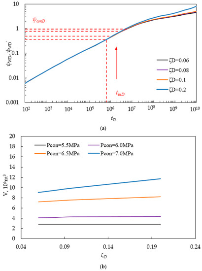
Figure 17.
(a) Comparison pressure with different fracture number; (b) comparison of CO2 storage capacity with different fracture number.
4. Conclusions
To gain quick and reasonable estimations of CO2 storage capacity for the MWPs scheme in a depleted SG reservoir, in this paper we develop a semi-analytical pressure-buildup model with consideration of MWPI. Model validation is implemented and calculation of CO2 storage capacity and sensitivity analysis are also conducted. Some meaningful conclusions are summarized as following:
- There is good agreement between our model and the numerical simulation; moreover, our approach runs faster than the numerical simulation, which demonstrates the accuracy and efficiency of our method.
- Comparing to SMFHWs, transient-pressure analysis demonstrates that the MWPs scheme has a severe MWPI phenomenon. Direct connection between wells through hydraulic fracture can stimulate the occurrence of MWPI. Our results suggest that wells will rapidly reach limited injection pressure due to the MWPI. CO2 storage capacity will be extremely overestimated by ignoring the MWPI.
- Increasing injection capacity (IC) will decrease the CO2 storage capacity. To improve CO2 storage capacity, it is beneficial to assign small CO2 injection rate to wells that are severely impacted by MWPI.
- Both the fracture number and fracture half-length have a positive influence on the CO2 storage capacity. Both of them have an approximate linear relationship with the CO2 storage capacity. Longer Lf is much more beneficial to improve CO2 storage capacity when the SG reservoir has bigger Pcon. For a given injection pressure, there is an optimal fracture number; the bigger the limited injection pressure, the smaller the optimal fracture number.
- Stress sensitivity has a positive influence on CO2 storage capacity; however, stress sensitivity generally occurs at the late production stage. Therefore, prolonging the injection period can improve CO2 storage capacity due to the occurrence of stress sensitivity.
This work proposes a systematic methodology for the estimation of the CO2 storage capacity for the MWPs scheme in depleted SG reservoirs. It provides new insights into CO2 storage capacity due to the existence of MWPI. Although we consider simple fracture configuration and only two wells, our method can be extended to complex fracture network configurations. Especially for the non-orthogonal fracture topology, our free-simulator method will enhance the calculation speed, which will be the objective in the future.
Author Contributions
Shenglai Yang and Zhan Meng designed the research; Lu Wang and Yun Jiang performed the research; Zhan Meng and Ziyao Zhong builded the model; Junru Wang and Chenggang Liang analyzed CMG experimental data; Zhan Meng and Jie Zou in charge of writing and story telling.
Conflicts of Interest
The authors declare no conflict of interest.
Abbreviations
| MWPs | multi-well pads |
| SG | shale gas |
| MWPI | multi-well pressure interference |
| SMFHWs | single multi-fractured horizontal wells |
| NFs | natural fractures |
| HFs | hydraulic fractures |
| DPP | dimensionless pseudo-pressure |
| DPPD | dimensionless pseudo-pressure derivation |
| IC | injection capacity |
| Nomenclature | |
| T | formation temperature, K |
| Pd | SG reservoir depleted pressure, MPa |
| ψd | SG reservoir depleted pseudo-pressure, MPa2/(mPa·s) |
| Tsc | temperature under standard conditions, K |
| psc | pressure at standard conditions, MPa |
| Ct | total compressibility, MPa−1 |
| ψ | pseudo-pressure, MPa2/(mPa·s) |
| ψf | fracture pseudo-pressure, MPa2/(mPa·s) |
| μ | gas viscosity, mPa·s |
| h | formation thickness, m |
| Lref | reference length, m |
| Φ | porosity, fraction |
| Lf1 | hydraulic fracture half-length of Well 1, m |
| Lf2 | hydraulic fracture half-length of Well 2, m |
| Lf3 | hydraulic fracture half-length of Well 3, m |
| Lf12 | fracture distance between Well 1 and Well 2, m |
| Lf32 | fracture distance between Well 3 and Well 2, m |
| t | time, h |
| x, y | coordination, m |
| r | radial distance, m |
| l | coordination of hydraulic fracture, m |
| v | integration variable |
| q1 | well production rate of Well 1, m3/d |
| q2 | well production rate of Well 2, m3/d |
| q3 | well production rate of Well 3, m3/d |
| qsc | well production rate under standard condition, m3/d |
| kri | initial permeability of formation, D |
| kf1 | permeability of hydraulic fractures for Well 1, D |
| kf2 | permeability of hydraulic fractures for Well 2, D |
| kf3 | permeability of hydraulic fractures for Well 3, D |
| Rm | matrix radius, m |
| V | gas concentration, sm3/m3 |
| wf1 | width of hydraulic fractures for Well 1, D |
| wf2 | width of hydraulic fractures for Well 2, D |
| wf3 | width of hydraulic fractures for Well 3, D |
| ζ | stress sensitivity coefficient, (mPa·s)/MPa2 |
| ρ | density, g/cm3 |
| Cg | gas compressibility, MPa−1 |
| M1 | total number of hydraulic fracture for Well 1, integer |
| M2 | total number of hydraulic fracture for Well 2, integer |
| M3 | total number of hydraulic fracture for Well 3, integer |
| tD | dimensionless time |
| qfD | dimensionless flux rate |
| qcD | dimensionless fracture rate |
| xD, yD | dimensionless space |
| rD | dimensionless radial distance |
| Lf1D | dimensionless hydraulic fracture half-length of Well 1, m |
| Lf2D | dimensionless hydraulic fracture half-length of Well 2, m |
| Lf3D | dimensionless hydraulic fracture half-length of Well 3, m |
| Lf12D | dimensionless fracture distance between Well 1 and Well 2, m |
| Lf32D | dimensionless fracture distance between Well 3 and Well 2, m |
| Lw12D | dimensionless distance between two wells, m |
| Cf1D | dimensionless hydraulic fracture conductivity for Well 1 |
| Cf2D | dimensionless hydraulic fracture conductivity for Well 2 |
| u | Laplace variable |
| Subscripts | |
| D | dimensionless |
| w12 | Well 1 and Well 2 |
| w32 | Well 2 and Well 3 |
| Superscripts | |
| — | Laplace transform |
Appendix A. Dimensionless Definitions
For the sake of simplicity, the following dimensionless variables will be used. The mathematical models can be written in dimensionless forms when the following dimensionless groups are defined:
For dimensionless pseudo-pressure in reservoir system and hydraulic fracture system,
where .
For the dimensionless time
where .
For the dimensionless spacing and fracture length
For the dimensionless gas rate influx, gas concentration, and gas flow rate can be defined, respectively:
For the fracture-flow model, the hydraulic fracture conductivity can be assumed to be uniform for the same well at the same time; the fracture conductivity can be varying for every well. Therefore, dimensionless fracture conductivity can be defined as
The dimensionless transmit coefficient of hydraulic fracture and SG formation can be presented as:
The dimensionless storage ratio of SG formation can be presented as:
The dimensionless adsorption index that denotes the SG desorption ability can be defined as
The dimensionless diffusion coefficient that denotes the SG transferring from matrix into natural fracture can be defined as
The dimensionless stress sensitivity coefficient can be defined as
Appendix B. Derivation of Line Source Solution
A SG reservoir is treated as a combination of a matrix system and a natural fracture system. To develop the mathematical models in a SG reservoir, the mathematical formula for a natural fracture system and a matrix system can be established separately and then dynamically coupled. To begin with, flow in natural fractures is assumed to be single phase by obeying Darcy’s law. Combining with the gas state equation and motion equation, the SG flow in a natural fracture system can be described as the following diffusion equation with consideration of gas adsorption behavior:
The pseudo-pressure function was used to account for the pressure-dependent gas properties; the governing Equation (A12) with the formula of pseudo-pressure is as follows:
The feature of stress-dependent permeability can be described by introducing a permeability modular ζ; the relationship between permeability and pseudo pressure is as follows (Pedrosa, 1986):
where kfi is the initial permeability of a natural fracture under initial pressure conditions, D; ζ is the permeability modular (mPa·s)/MPa2; and ψi is the initial pseudo-pressure, MPa2/(mPa·s).
Submitting Equation (A14) into Equation (A13), the final governing formula for a natural fracture system can be transformed as follows:
Then, the flow in the matrix system is treated as pseudo-steady state desorption, which satisfies Fick’s diffusion. In our work, the shale matrix is conveniently treated as spherical geometry. According to Fick’s law, the gas flow in the matrix system can be described as follows:
The adsorption behavior of SG is described by Langmuir isotherm equation [34]. Thus,
where kr is the permeability of SG formation, D; ψ is the pseudo-pressure in the fracture system, MPa2/(mPa·s); μ is the viscosity of shale gas, mPa·s; Φ is the porosity of the fracture system, fraction; Ct is the total compressibility coefficient, 1/MPa; V is the shale gas concentration in matrix, sm3/m3; t is the time, h; r is distance, m. Psc is the pressure at standard condition, MPa; Tsc is the temperature at standard condition, K; T is the formation temperature, K; D is gas diffusion coefficient, m2/s; Rm is the radius of sphere matrix, m; VE is the initial concentration in matrix, sm3/m3.
A series of comprehensive diffusion equations should be combined with the following initial and boundary condition,
The initial condition:
Based on the theory of line sink, the inner condition is presented as follows:
where q is the production rate of the line sink, sm3/d; and h is the thickness of the reservoir, m.
The reservoir is assumed to be infinite, and the outer boundary is as follows:
For convenience, some dimensionless variables have been defined previously. With the definition of these dimensionless variables, Equations (A12)–(A20) with the dimensionless formation can be presented as follows:
Natural fracture system:
Matrix system:
Dimensionless initial and boundary conditions:
It is observed that Equation (A21) contains strong non-linearity and it is hardly possible to obtain the analytical solution with conventional methods; therefore, the perturbation technology and the Presoda transformation are applied to linearize the equations [35]:
According to the theory implemented by Presoda [35], we perform a parameter perturbation in ζD by defining the following series:
considering that the value of ζD, the dimensionless stress sensitivity coefficient, is always small, the zero-order perturbation solution can meet the requirements, Therefore, the final formulations of Equations (A22) and (A23) are as follows:
Dimensionless initial and boundary conditions:
The Laplace transformation is a general method to deal with Equations (A28)–(A31); the Laplace transform is based on tD and functions as follows:
We can obtain the governing equation of a SG reservoir system in the Laplace domain:
Dimensionless boundary conditions:
where VED represents the dimensionless gas concentration on the surface of the matrix, which can be determined by the fracture pressure. Based on the Langmuir isotherm function, the absorption behavior of SG can be described as follows:
where .
Finally, substituting Equation (A34) into Equation (A33), one can get the following governing equation combining a natural fracture system and a matrix system:
where .
The general solution of Equation (A38) for the infinite-acting SG reservoir can be given by (Ozkan and Raghavan 1991, Xiao et al., 2016)
By the requirement that PD vanish at infinity, we must have A = 0 in Equation (A39). From the condition given by Equation (A36), we can obtain
By applying the principle of integration, the pressure distribution of a random position (xD, yD) caused by one fracture segment (xwD, ywD) is given by the following equation:
Appendix C. Derivation of Flow Solution in Hydraulic Fracture
The CO2 flow inside hydraulic fractures is assumed to be compressible and can be described by the 1D coordinates (Figure 5):
Based on the mass conservation theory, the corresponding governing equation can be presented as follows:
Furthermore, the corresponding governing equation with the formula of pseudo-pressure can be presented as follows:
with initial condition
As seen in Figure 2b and Figure 5, the interaction of hydraulic fractures between two wells for the MWPs scheme can be classified into two scenarios: with direct connection and without direct connection. Therefore, the boundary condition can be varying and described as follows:
When hydraulic fractures are not in direct connection between two wells (Figure 5a), the inner boundary comes into contact with the wellbore, thus
Because there is no fluid transportation at the tip of the hydraulic fracture, the outer boundary condition can be presented as follows:
When hydraulic fractures are in connection between two wells (Figure 5b), the two tips of hydraulic fracture separately make contact with Well 1 and Well 2, thus
With the definition of dimensionless variables mentioned in Appendix A, the flow equations with the dimensionless formula can be presented as follows:
and initial condition,
When hydraulic fractures are not connected between two wells, the inner boundary is in contact with the wellbore, thus
The outer boundary condition can be presented as follows because there is no flow transportation at the tip of the fracture:
When hydraulic fractures are connected between two wells, the two tips of hydraulic fracture separately contact with Well 1 and Well 2, thus
References
- Godec, M.; Koperna, G.; Petrusak, R.; Oudinot, A. Enhanced Gas Recovery and CO2 Storage in Gas Shales: A Summary Review of its Status and Potential. Energy Procedia 2014, 63, 5849–5857. [Google Scholar] [CrossRef]
- Bustin, R.M.; Cui, X.; Chikatamarla, L. Impacts of volumetric strain on CO2 sequestration in coals and enhanced CH4 recovery. AAPG Bull. 2008, 92, 15–29. [Google Scholar] [CrossRef]
- Kurniawan, Y.; Bhatia, S.K.; Rudolph, V. Simulation of binary mixture adsorption of methane and CO2 at supercritical conditions in carbons. AIChE J. 2006, 52, 957–967. [Google Scholar] [CrossRef]
- Martineau, D.F. History of the Newark East Field and the Barnett Shale as a gas reservoir. AAPG Bull. 2007, 91, 399–403. [Google Scholar] [CrossRef]
- Busch, A.; Alles, S.; Gensterblum, Y.; Prinz, D.; Dewhurst, D.N.; Raven, M.D.; Stanjek, H.; Krooss, B.M. Carbon dioxide storage potential of shales. Int. J. Greenh. Gas Control 2008, 2, 297–308. [Google Scholar] [CrossRef]
- Busch, A.; Alles, S.; Krooss, B.M.; Stanjek, H.; Dewhurst, D. Effects of physical sorption and chemical reactions of CO2 in shaly caprocks. Energy Procedia 2009, 1, 3229–3235. [Google Scholar] [CrossRef]
- Busch, A.; Gensterblum, Y. CBM and CO2-ECBM related sorption processes in coal: A review. Int. J. Coal Geol. 2011, 87, 49–71. [Google Scholar] [CrossRef]
- Kang, S.M.; Fathi, E.; Ambrose, R.J.; Akkutlu, I.Y.; Sigal, R.F. Carbon dioxide storage capacity of organic-rich shales. Presented at the Annual Technical Conference and Exhibition, Florence, Italy, 20–22 September 2010. SPE 134583. [Google Scholar]
- Tian, H.; Liu, S.B.; Chen, J.P. Overmature shale gas storage capacityevaluation. Presented at the International Petroleum Technology Conference, Beijing, China, 26–28 March 2013. SPE 16774. [Google Scholar]
- Tao, Z.Y.; Clarens, A. Estimating the carbon sequestration capacity of shaleformations using methane production rates. Environ. Sci. Technol. 2013, 47, 11318–11325. [Google Scholar] [CrossRef] [PubMed]
- Sondergeld, C.H.; Ambrose, R.J.; Rai, C.S.; Moncrieff, J. Micro-structural studies of gas shales. Presented at the SPE Unconventional Gas Conference, Pittsburgh, PA, USA, 23–25 February 2010. SPE 131771. [Google Scholar]
- Cipolla, C.L.; Lolon, E.P.; Erdle, J.C.; Rubin, B. Reservoir modeling in shale-gas reservoirs. SPE Reserv. Eval. Eng. 2010, 13, 638–653. [Google Scholar] [CrossRef]
- Moinfar, A.; Sepehrnoori, K.; Johns, R.; Varavei, A. Coupled geomechanics and flow simulation for an embedded discrete fracture model. Presented at the Reservoir Simulation Symposium, Woodlands, TX, USA, 18–20 February 2013. SPE 163666. [Google Scholar]
- Edwards, R.W.; Celia, M.A.; Bandilla, K.W.; Doster, F.; Kanno, C.M. A Model to Estimate Carbon Dioxide Injectivity and Storage Capacity for Geological Sequestration in Shale Gas Wells. Environ. Sci. Technol. 2015, 49, 9222–9229. [Google Scholar] [CrossRef] [PubMed]
- Zhao, Y.L.; Zhang, L.H.; Wu, F. Pressure transient analysis for multi-fractured horizontal well in shale gas reservoirs. J. Pet. Sci. Eng. 2012, 90–91, 31–38. [Google Scholar] [CrossRef]
- Yu, W.; Al-Shalabi, E.W.; Sepehrnoori, K. A sensitivity study of potential CO2 injection for enhanced gas recovery in Barnett Shale Reservoirs. Presented the SPE Unconventional Resources Conference, Woodlands, TX, USA, 1–3 April 2013. SPE 169012. [Google Scholar]
- Yu, W.; Lashgari, H.; Sepehrnoori, K. Simulation study of CO2 huff-n-puff process in Bakken tight oil reservoirs. Presented the SPE Western North American and Rocky Mountain Joint Regional Meeting, Denver, CO, USA, 16–18 April 2014. SPE 169575. [Google Scholar]
- Liu, F.Y.; Ellett, K.; Xiao, Y.; Rupp, J.A. Assessing the feasibility of CO2 storage in the New Albany Shale (Devonian-Mississippian) with potential enhanced gas recovery using reservoir simulation. Int. J. Greenh. Gas Control 2013, 17, 111–126. [Google Scholar] [CrossRef]
- Liu, M.; Xiao, C.; Wang, Y.; Li, Z.; Zhang, Y.; Chen, S.; Wang, G. Sensitivity analysis of geometry for multi-stage fractured horizontal wells with consideration of finite-conductivity fractures in shale gas reservoirs. J. Nat. Gas Sci. Eng. 2015, 22, 182–195. [Google Scholar] [CrossRef]
- Tian, L.; Xiao, C.; Liu, M.; Gu, D.; Song, G.; Cao, H.; Li, X. Well testing model for multi-fractured horizontal well for shale gas reservoirs with consideration of dual diffusion in matrix. J. Nat. Gas Sci. Eng. 2014, 21, 283–295. [Google Scholar] [CrossRef]
- Chen, Z.; Liao, X.; Zhao, X.; Feng, X.; Zang, J.; He, L. A new analytical method based on pressure transient analysis to estimate CO2 storage capacity of depleted shale: A case study. Int. J. Greenh. Gas Control 2015, in press. [Google Scholar] [CrossRef]
- Xiao, C.; Tian, L.; Yang, Y.; Zhang, Y.; Gu, D.; Chen, S. Comprehensive Application of Semi-analytical PTA and RTA to Quantitatively Determine abandonment Pressure for CO2, Storage in Depleted Shale Gas Reservoirs. J. Pet. Sci. Eng. 2016, 146, 813–831. [Google Scholar] [CrossRef]
- Awada, A.; Santo, M.; Lougheed, D.; Xu, D.; Virues, C. Is That Interference? A Workflow for Identifying and Analyzing Communication through Hydraulic Fractures in a Multi-Well Pad. SPE J. 2015, 21. [Google Scholar] [CrossRef]
- Guindon, L. Determining Interwell Connectivity and Reservoir Complexity through Fracturing Pressure Hits and Production-Interference Analysis. J. Can. Pet. Technol. 2015, 54. [Google Scholar] [CrossRef]
- Farley, T.; Hutchinson, T. Multi-Well Facility Optimization. In Proceedings of the Unconventional Resources Technology Conference, Denver, CO, USA, 25–27 August 2014; pp. 2656–2660. [Google Scholar] [CrossRef]
- Sardinha, C.M.; Petr, C.; Lehmann, J.; Pyecroft, J.F.; Merkle, S. Determining Interwell Connectivity and Reservoir Complexity through Frac Pressure Hits and Production Interference Analysis. In Proceedings of the SPE/CSUR Unconventional Resources Conference, Calgary, AB, Canada, 30 September–2 October 2014. [Google Scholar] [CrossRef]
- Kaviani, D.; Valko, P.P.; Jensen, J.L. Application of the Multiwell Productivity Index-Based Method to Evaluate Interwell Connectivity. In Proceedings of the SPE Improved Oil Recovery Symposium, Tulsa, OK, USA, 24–28 April 2010. [Google Scholar] [CrossRef]
- Zeng, F.; Zhao, G. The optimal Hydraulic Fracture Geometry under Non-Darcy Flow Effects. J. Pet. Sci. Eng. 2010, 72, 143–157. [Google Scholar] [CrossRef]
- Jia, P.; Cheng, L.; Huang, S.; Cao, R.; Xu, Z. A Semi-Analytical Model for Production Simulation of Complex Fracture Network in Unconventional Reservoirs. In Proceedings of the SPE/IATMI Asia Pacific Oil & Gas Conference and Exhibition, Nusa Dua, Bali, 20–22 October 2015. [Google Scholar] [CrossRef]
- Zhou, W.; Banerjee, R.; Poe, B.D.; Spath, J.; Thambynayagam, M. Semianalytical Production Simulation of Complex Hydraulic-Fracture Networks. SPE J. 2014, 19. [Google Scholar] [CrossRef]
- Cinco, L.H.; Samaniego, V.F.; Dominguez, A.N. Transient Pressure Behavior for a Well with a Finite-Conductivity Vertical Fracture. Soc. Pet. Eng. J. 1978, 18. [Google Scholar] [CrossRef]
- Feng, Y.; Gray, K.E. A parametric study for wellbore strengthening. J. Nat. Gas Sci. Eng. 2016, 30, 350–363. [Google Scholar] [CrossRef]
- Stehfest, H. Numerical inversion of Laplace transform. Commun. ACM 1970, 13, 47–49. [Google Scholar] [CrossRef]
- Birdi, K.S. Surface Chemistry and Geochemistry of Hydraulic Fracturing; CRC Press: Boca Raton, FL, USA, 2016. [Google Scholar] [CrossRef]
- Pedrosa, O.A., Jr. Pressure transient response in tress-sensitive Formation. In Proceedings of the SPE California Regional Meeting, Oakland, CA, USA, 2–4 April 1986. [Google Scholar]
© 2017 by the authors. Licensee MDPI, Basel, Switzerland. This article is an open access article distributed under the terms and conditions of the Creative Commons Attribution (CC BY) license (http://creativecommons.org/licenses/by/4.0/).