1. Introduction
The room-and-pillar mining method is widely used in many coal producing countries, including the U.S., China, India, and South Africa [
1,
2,
3,
4]. Compared with other underground mining methods, room-and-pillar mining can effectively control ground subsidence and minimize the effects on the surface structure [
5,
6]. However, the collapse of a single pillar in the mine shaft can cause load transfer to the neighboring pillars and subsequently results in ground subsidence at the surface. In some cases, cascading pillar failures or sinkholes may result if the neighboring pillars cannot carry the additional load, or if the resulting roof span is too large for effective load transfer [
7,
8,
9,
10,
11,
12]. Post-pillar-failure disasters, such as collapse-induced earthquakes and non-uniform ground subsidence may also appear during, or after, mining activities, threatening the safety of people and infrastructures [
2,
7,
11]. The literature indicates that the pillar failure may occur in a couple of hours or decades after mine abandonment [
5,
13,
14,
15]. The long-term stability means that the coal pillar can be stable in the long-term after the mining panels or coal mines are closed, and there will be no ground subsidence or post-mining damages on the ground surface structures that are induced by pillar instability.
Since the width–height ratio of pillars is smaller in room-and-pillar mines, pillar failures appear more frequently in room-and-pillar mining than stripe mining. Records of U.S. pillar failures showed that the pillar failures are usually accompanied by sudden roof subsidence, pillar spalling, or floor heave, and such failures appear more frequently when width–height ratios of pillars are smaller than 3 for coal mines, less than 2 for non-mental mines, and less than 1 for metal mines [
7]. The experiences from South Africa and Australia also showed that the coal pillars with low width–height ratio have better tendency to collapse with time [
14,
16]. It is concluded that the collapses of slender pillars with width–height ratio ranging from 3 to 4 will be brittle and may lead to cascading pillar failures, the failures of intermediate pillars with width–height ratios of 4–8 will make the pillars “squeeze” to non-violent rib spalling and, finally, the squat pillars with width–height ratios larger than 8 will hardly fail [
14,
17].
Studies on the long-term stability of mineral pillars showed that, over time, weathering and stress will eventually result in pillar size reduction and pillar strength degradation [
18,
19,
20,
21]. The dissolution of minerals in rock-like materials, for example, may reduce the effective size of mineral pillars [
19], or may increase the micro cracks and damages in the material, leading to low-stress material failures [
22]. Some mineral partings in coal pillars are more sensitive to water and will peel from the pillar, reducing the pillar size [
18]. On the other hand, high overburden stress can cause progressive rib spalling of pillars [
20]. Such progressive pillar failure resulting from the coupled effects of weathering and stress is defined as pillar scaling or pillar peeling.
To predict pillar life, a constant pillar scaling rate has been proposed by Van der Merwe [
13,
23] and Sami et al. [
21]. However, because of the complicated coupling effect of weathering and stress, the constant pillar scaling rate is empirical, site-specific, and difficult to obtain reliable results on pillar stability or pillar life. Salamon [
24] suggested that the coal debris spalled from pillar ribs during peeling can restrict the further scaling of a coal pillar, and propose a pillar peeling model, which can be used to calculate the ultimate scaling of the pillar. Backfill mining experiences indicate that the confinement of the non-cohesive backfill can restrict the pillar dilating and may enhance pillar strength, providing support to Salamon’s concept [
25,
26].
Considering the size reduction and peeling behaviors of coal pillars, this paper proposes a conservative pillar peeling model. The peeling model assumed that a pillar will slowly peel off as long as the pillar rib is not covered by loose coal debris piles. Thus, it represents the worst case scenario of a pillar. The effects of peeled coal debris pile on coal pillar stability are investigated by numerical simulations. The peeling model is verified by 500 failed and stable pillar cases. Finally, failure of a single pillar on the stability of surrounding pillars are analyzed, and a long-term stability evaluation method is proposed.
2. Coal Pillar Peeling Model
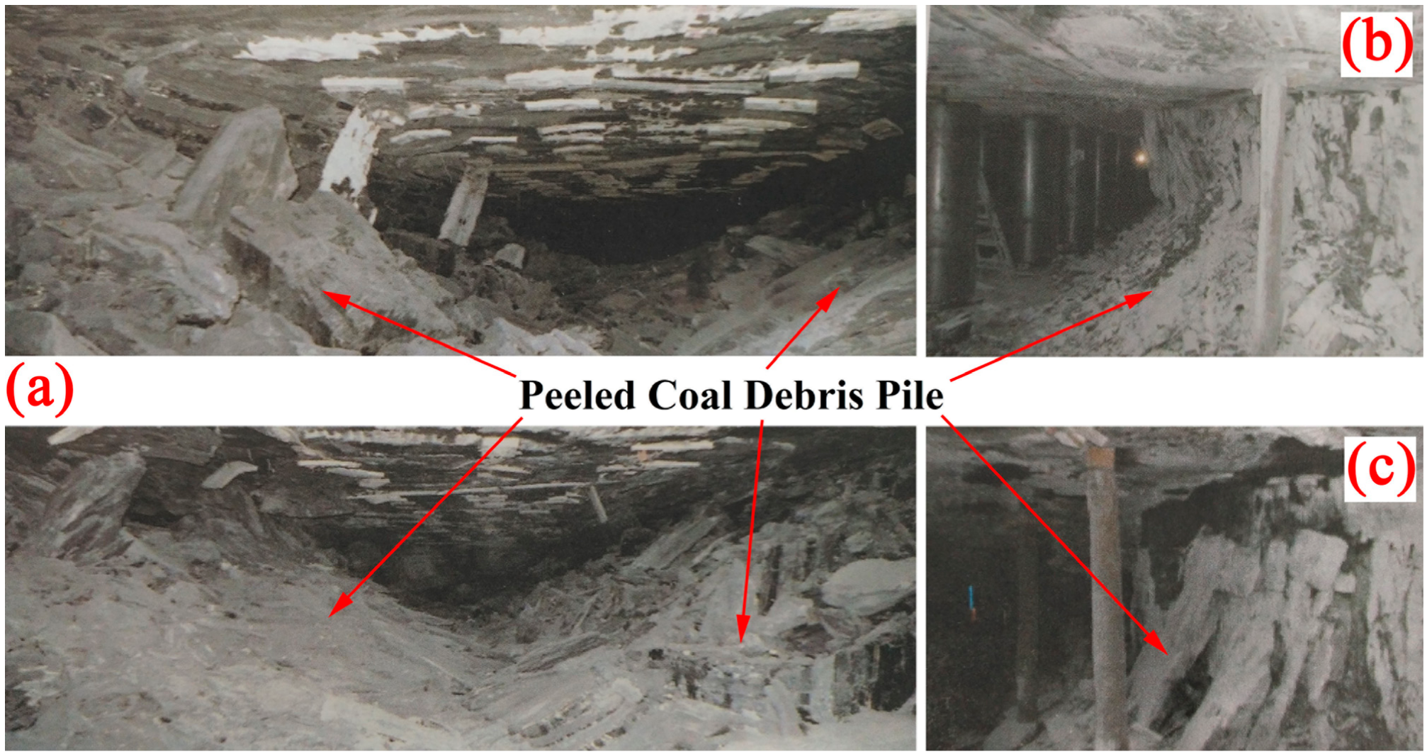
As long as the pillar rib is exposed to the environment without horizontal confinements, it will suffer from the long-term exposure to weathering and stress. The pillar rib may slowly peel off and the pillar size may scale down because of such effects. The coal debris spalled from the pillar rib during the peeling process will accumulate around the coal pillars, providing a volume restriction to the coal pillars and protecting the internal pillar rib from further environmental weathering.
Figure 1 shows some engineering cases about distribution of coal debris around peeling pillars [
2].
Salamon [
24] first proposed a pillar peeling model for square pillar to describe this situation and assumed that the pillar is scaling down uniformly towards the pillar center. The peeled coal debris then accumulates around the pillar and forms a triangle pile. The peeling progress will stop if the coal debris pile fully covers the coal pillar. However, the assumption of uniformly peeling may underestimate the maximum peeling depth in the coal pillars—the peeling at the pillar bottom is less than that at pillar top. On the other hand, the laws of pillar rib spalling indicated that the rib spall appear more frequently near the pillar top, and the possibility of spalling increases as the pillar height increases [
27,
28,
29]. It is, therefore, more reasonable to assume a non-uniform pillar peeling model to make a safer stability evaluation.
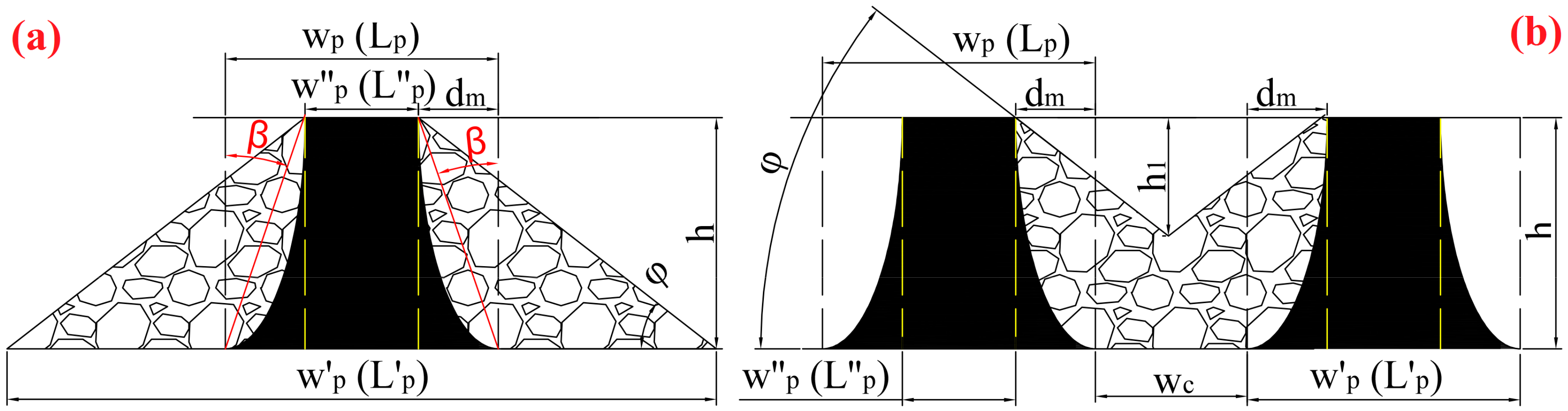
Figure 2 shows the diagram of a non-uniform peeling model where the shape of the peeled coal debris is affected by the room width: a triangle pile will form if the room width is large (an isolated pillar case,
Figure 2a), whilst the coal debris from two pillars will overlay each other if the room width is small (a non-isolated pillar case,
Figure 2b). Assuming that the peeling of the coal pillar is non-uniform towards the pillar center and the peeled cross-section can be represented by a quarter of an ellipse—the semi-major axis of the ellipse will represent the pillar height and the semi-minor axis represents the maximum peeling depth on the pillar.
For an isolated rectangle pillar, the spalled coal debris are the granular materials piling up around the pillar in a triangle shape, the progressive peeling will stop if the coal debris pile reach the pillar top and the bottom angle of the pile will approximate the repose angle
. Equations (1)–(5) can be proposed based on the geometry in
Figure 2a:
where
is the repose angle, °;
is the maximum peeling depth on a single side of a pillar;
and
are the initial pillar width and pillar length respectively;
and
are minimum pillar width and pillar length after peeling; h is the pillar height;
and
are the bottom width and bottom length of the trapezoidal column.
The pillar peeling process can be assumed as four elliptical cylinders cutting through the coal pillar; thus, the total volume of peeled parts on coal pillar
and the volume of the residual pillar
can be calculated:
and the volume of the trapezoidal column
is:
The peeled volume of coal pillar
will increase with a bulk factor,
k, and equals the volume of the peeled coal debris pile:
Combining Equations (1)–(9), the maximum peeling depth can be calculated as:
Define the minimum room width leading to an isolated pillar as the critical room width
, then:
Figure 2b shows the case when the room is smaller than the critical room width. For a single pillar, the combination of the residual pillar and the coal debris pile consists of a trapezoidal column and a rectangle cube base, and the following can be used:
where
is the room width, m;
is the total volume of the trapezoidal column and the rectangle cube base, m
3.
Combing Equations (1)–(7) and Equations (12)–(14), the maximum peeling depth when the room width is smaller than
can be calculated as:
Thus, the maximum peeling depth of pillar for all conditions can be determined by Equations (10), (11), and (15). When the room width is larger than the critical room width , Equation (10) should be used, otherwise, Equation (15) should be used.
3. Effects of Pillar Width–Height Ratio on Pillar Peeling
According to
Figure 2, the maximum peeling depth
can also be represented by the peeling angle
, which reflects the degree of peeling damage on a pillar: The larger
is, the more severe the peeling damage will be. Considering the
case, as the pillar will totally peel when
=
/2, the maximum peeling angle
that a pillar can bear is:
Equation (16) indicates that is only related to the pillar width–height ratio. A pillar with a large width–height ratio has a larger , and has a better ability to resist the pillar peeling.
Using
to represent
, Equations (10), (11), and (15) can be transformed as:
where
is the initial width–height ratio of pillar;
is the critical width–height ratio of the room
and
coefficients related to bulking factor
.
,
, and
R =
.
is only related to the repose angle, bulk factor, and width–height ratios of the pillar and room.
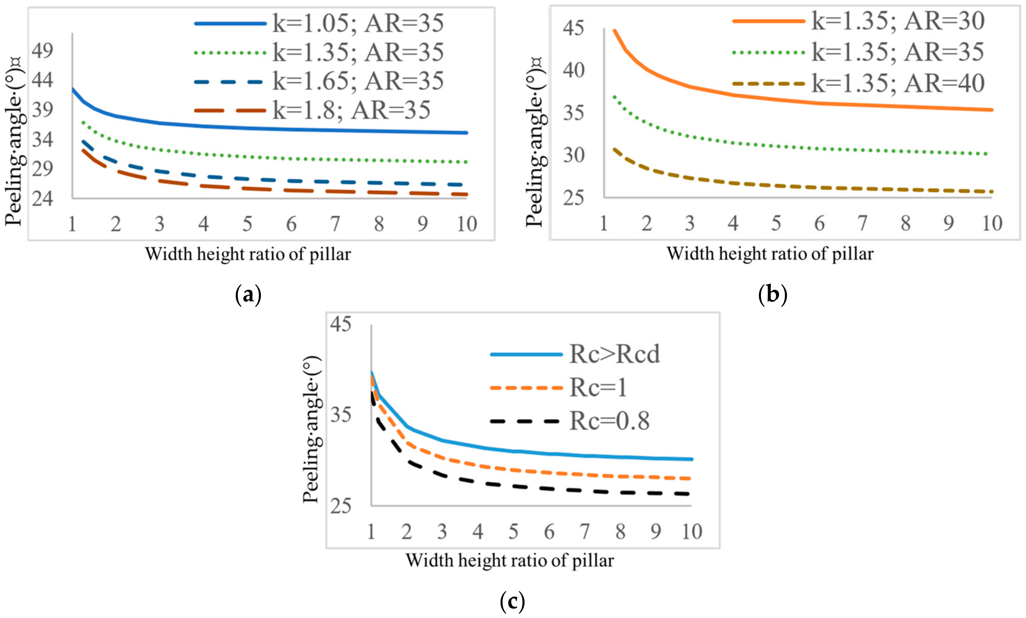
Figure 3a,b shows the relationships between the peeling angle
and width–height ratio of an isolated pillar.
will exponentially increase when the pillar width–height ratio is smaller than 3, which explains why the cascading pillar failures occur more frequently for slender pillars: slender pillars have smaller
and larger
and will result in severe peeling damages when
is reached or exceeds
. Increases of the bulk factor and repose angle can significantly decrease
, which means the stronger and stiffer the pillar is, it can have a better ability to resist the peeling process. This offers the explanation of why the pillar width–height ratio leading to cascading pillar failures is smaller than 2 for non-metal mines, but is smaller than 3–4 for coal mines [
7]. The bulk factor is usually 1.6–1.8 for sandstone and is usually smaller than 1.3 for coal. If a coal pillar and a sandstone pillar have the same width–height ratio, then
of the sandstone pillar is significantly smaller than the
of the coal pillar (
Figure 3a), and the peeling damage will be more severe on the coal pillar.
Figure 3c shows the relationships between the peeling angle
and width–height ratio of non-isolated pillars:
decreases if the room width decreases. However, such a decrease is not obvious when the pillar width–height ratio is small.
4. Effect of Peeled Debris Pile on Pillar Stability
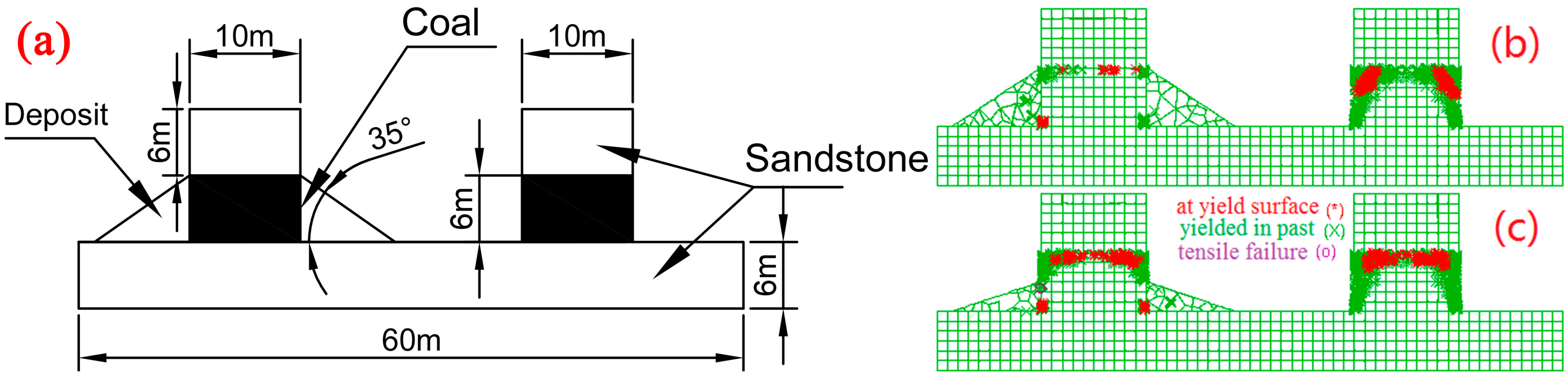
To study the effect of peeled coal debris pile on pillar stability, UDEC is used to model peeling pillars. The Mohr-Coulomb failure criterion is assumed for material failures. The numerical model has two pillars, in which one pillar was surrounded by triangle-shaped, peeled debris piles and the other pillar was just a single pillar (
Figure 4a). For simplicity, we assume that the piles consist of rigid coal fragments and the coal fragments in the pile are only affected by internal frictions. The properties of the coal fragments are the same as of the coal pillars, but the interface strength between the coal fragments is assumed to be zero. The model base is fixed and the pillars are covered by sandstone roofs. Overburden pressure is represented by a static vertical stress of 1.1 MPa applied on the top of the sandstone roof. The mechanical properties of the model are adopted from the Yulin mining area in China [
30] and are listed in
Table 1. The element size of the model is 0.2 m. Static equilibrium analysis is then conducted with consideration of gravity loading to the system.
Figure 4b,c show the simulation results which indicate that the yielding of the pillars caused by overburden stress is more severe at the pillar top. This means the non-uniform peeling assumption is reasonable. As the pillar peels away slowly, the actual stress on the pillar gradually increases and the yield zone of the pillar increases, eventually leading to pillar failure. The yield zone is reduced if the pillar is surrounded by a coal debris pile, which restricts the horizontal deformation of the coal pillar, and the stress condition is closer to a triaxial stress state instead of a uniaxial stress state (
Figure 4b). The decrease of the debris pile height will expand the yield zone in the pillar, but the overall stability of the pile-affecting pillar is still better than the single pillar (
Figure 4c). Therefore, the peeling progress can be considered to stop when the pile height equals to the pillar height, because the further development of yielding areas would cease and the pillar strength is enhanced.
5. Application of the Peeling Model in Case Studies
Mine data on 354 stable and 145 failed pillars have been collected from China [
31], South Africa [
13,
15,
16], and India [
1,
32]. The stability of these pillars are evaluated and discussed in the following:
The initial stress (
) on pillars and their initial safety factors (
) can be calculated by tributary area theory, and the initial pillar strengths (
) are estimated by the Salamon formula:
where
is the average density of overburden strata in kg/m
3;
is the acceleration of gravity, N/kg;
H is the mining depth, m; and
is the coal strength, MPa.
The stress on pillars (
), pillar strength (
), and safety factor (
) after peeling can, thus, be calculated as:
The Salamon formula was based on back-analysis of both stable and failed pillars, but did not consider the peeling progress. Hence, it may underestimate the coal strength
(7.176 MPa). Since it is very likely that the pillar peels before it collapses, the actual pillar width should be used instead of the nominal pillar width. Therefore, the uniaxial compressive strength (UCS) of coal was utilized to calculate the pillar strength. It should also be noted that the database from South Africa includes some highly joint-influenced coal fields and the coal pillars have very low strength. According to York [
16], the strength of these coal pillar can be as low as 40% of the pillar strength in other mining areas. Thus, the database from South Africa was divided into ordinary coal fields (ZA-N) and weak coal fields (with highly-jointed strata, ZA-W). An averaged USC of 21 MPa is used to represent the coal strength for ordinary coal fields in South Africa [
33], and 8.4 MPa (40% of 21 MPa) for weak coal fields.
The bulk factor
k and the repose angle
are needed to calculate the peeling depth
. The bulk factor of coal is usually 1.05–1.2, and the stronger the coal is the larger the bulk factor will be [
34]. The repose angle of non-compacted coal is usually about 27–45° [
35] and studies indicated that the angles are affected by the angularity of rock materials, the particle size, and the material inhomogeneity etc. [
36,
37]. The repose angle or coal debris properties of the collected cases are not provided in the literature; hence, for simplicity, it is assumed that the weak coal is harder to form angular shaped particles and has smaller particle sizes than the stronger coal: the repose angle of coal from ordinary coal seam is assumed to be 40°, while the repose angle of weak coal is assumed to be 30°. The parameters used in Equations (23)–(25) are listed in
Table 2.
Table 3 shows the failed and stable pillar cases in China. Most initial safety factors of failed pillars in China are larger than 1, which is consistent with actual site conditions: these pillars were stable during mining activities, but fail after mine abandonment. The safety factor after peeling in
Table 3 shows that only one case is incorrectly computed, and the initial safety factors do not show any pillar collapse. The results from India and South Africa are provided as
supplementary materials as they had been provided by other researchers.
Table 4 shows the evaluation accuracy of 145 failed pillars and 354 stable pillars. Pillar failure is time-dependent and stable pillars may still have a danger of collapse in the near future. The evaluation accuracy should refer to the failed pillar cases. To determine the evaluation accuracies, South Africa pillar cases have been studied with classical pillar design methods and pillar peeling model methods: in the classical pillar design method, the Salamon formula with a constant coal strength of 7.2 MPa and a critical safety factor of 1.6 are widely accepted in room-and-pillar mines in South Africa [
16]. In the failed pillar cases, if the coal strength is 7.2 MPa, the evaluation accuracy is 26% for weak coal fields, but if the joint effects were considered and the coal strength is reduced to 40% and the accuracy for weak coal fields is improved to 92%, indicating that the strength assumption for weak coal field is acceptable. The evaluation accuracy of classical pillar design method is above 90% for South Africa. The pillar peeling model uses coal USC as the coal strength in the Salamon formula, and a safety factor of 1 as the critical safety factor, the evaluation accuracies of all three countries are above 90%. Therefore, the peeling model is considered acceptable. In stable cases, the evaluation accuracy of peeling model is more than 70% for ordinary coal fields, but is 55% for weak coal fields, this indicated that 27% of Indian pillars, 20% ordinary coal pillars, and 45% weak coal pillars in South Africa still face long-term stability issues.
The overall evaluation accuracies between the classical pillar design method and pillar peeling method are similar in South African cases. This indicates that the classical method with a coal strength of 7.2 MPa and a safety factor 1.6 contains the pillar peeling. However, the pillar failure mechanism cannot be revealed by this method, and it is only suitable for South African mining areas. On the contrary, the pillar peeling model can better explain the reason for subsequent failure of initially-stable pillars, and the peeling model uses the coal UCS and a theoretical safety factor of 1 to evaluate pillar stability; thus, it has better applicability for other mining areas. When utilizing the pillar peeling model for long-term pillar stability evaluation, the coal strength
in Equation (24) should be calibrated by the realistic situation. For example, the ZA-W coal fields (
Table 2) were affected by highly-jointed strata, the coal strength for this coal fields was calibrated according to the study [
16]. The
in Equation (24) is recommended to be the long-term coal strength when conducting pillar stability evaluation (e.g.,
is the creep strength if there exists unstable creep behavior;
is the saturated coal strength if the coal pillar is saturated by water, etc.)
6. Effect of Single Pillar Failure on Surrounding Pillars
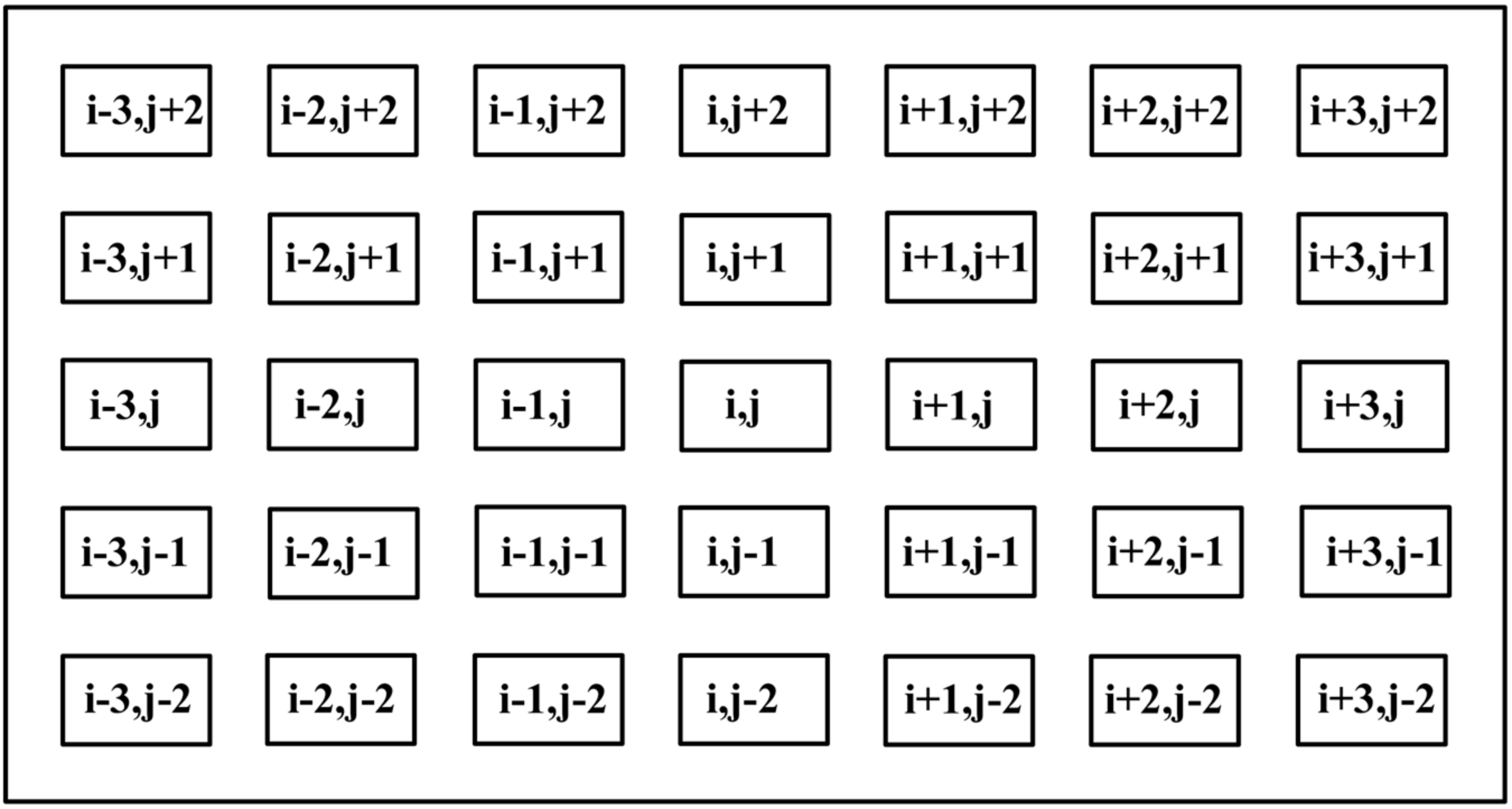
Assuming that the overburden strata do not cave in, the square pillars are evenly distributed in the goaf, the working panel is flat, and the effect of a single pillar failure on surrounding pillars is then considered.
Figure 5 shows the layout of a room-and-pillar mine site, where the row number of pillars is defined as 1, 2, 3, …,
i and the column number of pillars is defined as 1, 2, 3, …,
j.
We define the pillars (
i − 1,
j), (
i + 1,
j), (
i,
j − 1), and (
i,
j + 1) as the abutted pillars of pillar (
i,
j), and pillars (
i − 1,
j − 1), (
i − 1,
j + 1), (
i + 1,
j − 1), and (
i + 1,
j + 1) as diagonal pillars of pillar (
i,
j). The failure of pillar (
i,
j) will transfer its load to four abutted pillars and four diagonal pillars; the abutted pillars are the closest pillars to the failed pillar and carry more transferred stress, while the diagonal pillars are further away to the failed pillar and carry less transferred stress. The weight of the transferred stress for a pillar can be calculated by the distance between failed pillar centers and surrounding pillar centers:
where
and
are the weights of the abutting pillar and diagonal pillar, respectively.
When one pillar fails, the stresses on the surrounding pillars are:
Therefore, if
i abutting pillars and
j diagonal pillars failed around a pillar, the stress on this pillar (
) and its safety factor (
) are:
Combining Equations (20)–(22) and Equations (31) and (32), the relationship between the initial safety factor and the safety factor after neighboring pillars fail can be calculated as:
where
i is the number of failed abutting pillars,
j is the number of failed diagonal pillars.
Table 5 shows the safety factor for a pillar after its neighboring pillars fail, the effect of diagonal pillar failure is smaller than the effect of abutting pillar failure on a stable pillar. If the initial safety factors of all pillars are 1, any pillar failure will destroy its neighboring pillars. Thus, it results in a likely cascading pillar failure. If the initial safety factor is 1.5, a pillar may still be stable after 50% of its neighboring pillars fail.
Table 6 shows the minimum initial safety factor that a pillar can be stable after all of its neighboring pillars fail. If a pillar has an initial safety factor of 2, it will still be stable after losing all of its neighboring pillars. This conclusion befits the historical data from pillar failures in Australia and South Africa well, in which the time-dependent pillar failures appear more frequently when the width–height ratio of pillar is smaller than 4 and the safety factor of the pillar is smaller than 1.5 [
14]. Hill [
14] also noted that the failed pillars with large width–height ratio ranging from 4 to 8 have safety factors around 0.7–1.5, while the failed pillars with safety factors larger than 2 have a width–height ratio of 2 and below. In the former case, the goaf cannot bear localized pillar failures and cannot prevent the domino-like failures. For the latter case, although the initial safety factor is large enough, the pillar peeling angle is also very large when the width–height ratio is 1–2 (
Figure 3). Based on these conclusion, the long-term pillar stability criterion is proposed in
Table 7.


