
Experimental Evaluation of the Thermal Performance of Raised Floor Integrated Radiant Heating Panels


1
Department of Architecture and Architectural Engineering, Graduate School of Seoul National University, Seoul 08826, Korea
2
Corporate R&D Center, LG Hausys, Anyang 14117, Korea
3
Department of Architecture and Architectural Engineering, College of Engineering, Seoul National University, Seoul 08826, Korea
*
Author to whom correspondence should be addressed.
Energies 2017, 10(10), 1632; https://doi.org/10.3390/en10101632
Submission received: 2 September 2017
/
Revised: 13 October 2017
/
Accepted: 13 October 2017
/
Published: 17 October 2017
Abstract
:In this study, we propose a method for the evaluation of the thermal output of radiant heating panels by employing a modification of the currently used method, which is recommended by existing standards, using cooling plates. We aim to overcome the absence in the measurement method of the downward thermal output as well as to address the challenges in the control of the heat transfer resistance of the heat transfer layer, which arise due to the contact resistance between the layers. Using the modified method, we compare the thermal performance of three types of raised floor integrated radiant heating panels that have different filler materials for the bottom insulation of the panel. We show that the most efficient sample panel is the one that is not filled with a material; with an efficiency of 70.1%. In addition, we show that the value of the gradient of the characteristic curve calculated by the existing method ranged between 7.2% to 14.9% larger than that obtained by modified method. This difference is attributed to the heat transfer resistance of the heat transfer layer that is present in the experiments, and has a value in the interval of 0.1096 to 0.1582 . This is caused by the contact resistance between the heat transfer layer and other layers, even though the heat transfer resistance of the heat transfer layer used in the experiment is 0.0985 . The modified method proposed in this study reveals that the experimental results are not influenced by the heat transfer resistance of the heat transfer layer. We also show that our experimental results are reproducible.
1. Introduction
Radiant systems had already been used as building heating systems in ancient Asia (the Korean ondol [1] and the Chinese kang [2]) and Europe (the Roman hypocaust) [3]. However, it was only at the beginning of the 1950s that radiant systems were widely rediscovered, and were used as mechanical heating systems for buildings [4]. At present, radiant floor heating systems are installed in almost all residential buildings in Korea [1] and in 85% of the rural houses in northern China [2]. Moreover, it has been reported that 30–50% of new residential buildings in Germany, Austria, and Denmark are equipped with radiant floor heating systems [5]. Recently, radiant heating systems have been widely used in residential as well as in non-residential buildings—such as office buildings, retail stores, and schools—and even in large-scale buildings, such as airport terminals, and railway stations.
As radiant heating systems are becoming more popular, the need to assess the various performances of radiant heating panels has become more pressing [6]. Among the various required performances of radiant heating panels, it is essential to evaluate their thermal performance, which is represented by the thermal output of a radiant heating panel.
The evaluation of the thermal output of each individual radiant heating panel is needed for the design of radiant systems and for comparing the thermal performance of different panels. Mechanical system designers can estimate the installation area of the panel and the maximum supply temperature and flow rate of the heating medium using the thermal output data obtained through the thermal performance evaluation. Based on these estimated values, the distribution system and plant can be designed. The thermal output data of radiant heating panels can be used for the comparison and evaluation of the thermal performance of various designs, products, and models of radiant panels. This enables the selection of panels that present better thermal performance for use in radiant system planning or in novel panel designs, such as RFIRHP.
To evaluate the thermal output, the heat transmittance of a heating panel should be obtained for the heat flux from the surface of the heating panel to be calculated. The heat transmittance, which describes the heat transfer rate from the hot water to the panel surface, can be deduced through calculation, simulation, or experimental methods.
Calculation methods (based on standards such as the EN 1264 [7], the NT VVS 127 [8], and the ASHRAE [9] standards) or simulation methods are useful in the simple evaluation of the thermal output. However, these methods are applicable to limited types of radiant heating panels, and it is difficult to deduce the heat transmittance of panels that comprise various materials and have complex layers and geometry. For this reason, an experimental approach is required for the evaluation of the thermal output of radiant panels.
In terms of experimental assessment, test chambers are typically used for the simulation of real indoor environmental conditions. The method in which test chambers are utilized presents the advantage of accuracy because it can simulate a real environment. However, to conduct this experiment, this method requires a large chamber, as well as a high number of sample panels to be installed inside the chamber.
Instead of employing a method that requires the use of a test chamber, the EN 1264 and NT VVS 127 standard have introduced an experimental method in which a sample radiant panel and cooling plates are used as an alternative to the chamber. As a referenced method in ISO 11855-2:2012, the sample radiant panel is configured to release heat to cooling plates, which are designed to simulate the room above and below the radiant panel [10]. The experimental method in which the cooling plates are used does not require a chamber, and the number of sample panels required for the evaluation of the thermal output of a radiant panel is small; hence, this method presents the advantage of saving time and cost, compared with the method in which a test chamber is used. Therefore, the experimental method in which cooling plates are used is very suitable to serve as a mock-up test for the evaluation of the thermal performance within the context of developing a new panel that comprises various materials and has complex layers and geometry; such panel is the RFIRHP.
It is important to evaluate the thermal output of the lower part (bottom)— hereinafter referred to as the downward thermal output—of RFIRHP because in the RFIRHP, it is difficult to attach the insulation to the bottom of the panel to ensure proper insulation of its lower part owing to the curved shape of the lower part. However, the existing method does not describe the method of measuring the downward thermal output of the sample panel. In addition, in the test method for evaluating the thermal output of the radiant panel using a cooling plate—which was introduced in the existing standards—it is necessary to strictly control the heat transfer resistance of the heat transfer layer that simulates the total heat transfer resistance between the radiant panel surface and the room; nevertheless, its control presents uncertainty. In the past few research works, a study on the evaluation method of the thermal output of the radiant panel using a cooling plate was conducted; however, they focused only on the control strategy to meet the target condition of the experiment [11] and did not focus on the downward thermal output of the panel [12].
In this study, to solve this problem, we propose a calculation method for the evaluation of the thermal output of radiant heating panels by employing a modification of the method that is recommended by existing standards through the use of a cooling plate. Using the modified method, the thermal performance of three types of RFIRHPs, with different filler materials for the bottom insulation of the panel, will be compared and evaluated. Based on this, additional suggestions will be offered regarding the improvement of the thermal performance of the RFIRHP. In addition, the experimental results will be calculated via the existing method, and the effectiveness of the modified method will be confirmed by comparing the results from the existing method with the results obtained from the modified method.
2. Raised Floor Integrated Radiant Heating Panel
The RFIRHP is a radiant floor panel with a water pipe system integrated in the raised floor module. It presents the advantages of a raised floor and of a radiant floor heating system. It ensures accessibility to cables without sacrificing the comfort and the energy-saving potential of the radiant floor heating system. In addition, the setting up of the system is fast, thus increasing the flexibility of the management. The RFIRHP is composed of various materials and has complex layers and geometry. An example of its configuration and cross section is shown in Figure 1.
The RFIRHP is a radiant heating panel and a raised floor; therefore, it must satisfy the requirements of thermal performance as a radiant heating panel and the requirements of structural performance as a raised floor. The RFIRHP has the same shape and structure as the existing raised floor because the newly added function of the radiant heating panel is achieved through the integration of water pipes, without modifying the design of the existing raised floor. Therefore, there is no issue regarding the structural performance of the RFIRHP as a raised floor; this can be easily verified through existing tests on the performance of the raised floor. However, the shape of the RFIRHP is different from that of the conventional configuration; hence, there is an issue regarding its thermal performance.
The radiant heating panel, as a type of terminal, heats the room because of the increase in the surface temperature of the panel; this increase in surface temperature is achieved by obtaining heat from the hot water that is supplied through a pipe, which is embedded in the panel. Heat transfer from the hot water to the surface of the radiant panel is dominated by conduction. The direction of heat transfer by conduction is determined by the temperature difference; thus, if a temperature difference exists, the heat obtained from the hot water is transferred to the top, bottom, and side surfaces of the panel.
The thermal output in the direction other than the direction of the room (in RFIRHP, this is the direction of the lower and the side surface of the panel) can be regarded as a loss in the terminal according to the principle of radiant heating. For this reason, the standards pertaining to radiant heating panels recommend that the panels be sufficiently insulated so that heat may not transmitted in any direction other than the direction of the room to be heated [7]. Therefore, it is desirable that the RFIRHP be designed in a manner such that heat transfer in the direction of the lower surface of the panel would be minimized to reduce losses to the lower space of the raised panel, as well as to avoid negative effects on the equipment at the lower space of the raised panel.
Owing to the structural performance requirements of the raised floor, the lower part of the RFIRHP typically has a curved shape, which resembles a dome (Figure 1). Therefore, it is difficult to attach the insulation to the bottom of the panel to ensure proper insulation of the lower part of the RFIRHP. Even if the insulation is attached to the lower part of the RFIRHP, the thickness of the panel increases with the thickness of the insulation; if the floor is maintained at the same level, either the height of the lower space of RFIRHP or the height of the upper space of RFIRHP would decrease. This is not economically feasible. In this study, the thermal performance of three types of RFIRHPs with different filler materials (no filling material, filled with perlite, and filled with urethane foam) at the internal void space of the RFIRHP (⑤ of Figure 1b) was evaluated to solve the lower-part thermal insulation problem of the RFIRHP (Table 1).
3. Experimental Methodology
In this study, we will evaluate the thermal performance of the RFIRHP through experiments, using a cooling plate. However, in the present study, certain problems arose in deriving the desired results using the experimental method introduced in the existing standards. In this section, we will propose a method for evaluating the thermal output of radiant heating panels using a cooling plate with the aim to evaluate the overall thermal performance of the RFIRHP. The proposed method is a modification of the method introduced in existing standards.
3.1. Heat Transfer from the Hot Water to the Room Around the Radiant Panel
When a space is heated using the radiant heating panel, heat is transferred from the hot water to the room. Heat transfer from the hot water to the room can be divided into two stages. The first is the heat transfer between the hot water and the radiant surface, and the second is the heat transfer between the radiant surface and the room (Figure 2). The former is the dominant heat transfer by conduction through the panel structure. On the other hand, the latter is heat transfer by convection between the radiant surface and the adjacent air, and heat transfer by radiation between the radiant surface and the other surface of the room.
The heat transfer between the radiant surface and the room is a general characteristic of the radiant panel. Regardless of the type of panel (different design, material, layer, etc.), if the difference between the mean radiant surface temperature and the room operative temperature is the same, the thermal output on the radiant surface is the same, as well. The relationship between the heat flow density and the mean differential temperature, which is referred to as the Characteristic Curve, only depends on the type of the heat-emitting surface (floor, wall, ceiling) and on whether the temperature of the surface is lower (cooling) or higher (heating) than the room operative temperature. The heat exchange coefficient is the parameter that affects the amount of heat transferred between the surface and room that is related to the surface types [13]. The Characteristic Curve of floor heating surfaces, such as the RFIRHP, is obtained from the following [13]:
where is the standard specific thermal output of the radiant panel , is the room operative temperature , and is the mean temperature of the radiant surface .
On the other hand, the heat transfer between the hot water and the radiant surface is an individual characteristic of the panel, and the heat transmittance of the panel is different for each type of panel (different design, material, layer, etc.). Therefore, by evaluating the thermal performance of the radiant panel we may find the value of the heat transmittance of the radiant panel as an individual characteristic via calculations, simulations, or experimental methods.
3.2. Experimental Method Based on the EN 1264 Standard
To perform the experimental assessment described in the EN 1264 standard, the configuration should be designed in such a manner that a room and its heat loss to ambient environment may be simulated. The aforementioned standards suggest two cooling plates to simulate the heating load of a room: one would simulate the heat loss to the room above the panel and the other would simulate the heat loss to the room below the panel.
A heat transfer layer is required to simulate the heat transfer resistance between the radiant surface and the room. The heat conduction resistance of the heat transfer layer should be carefully determined to simulate the sum of the convection and radiation heat transfer resistances, . This heat transfer layer is located between the cooling plate and the sample radiant panel (Figure 3).
The target condition must be satisfied for the experiment. The target condition refers to the condition where the radiant heating panel yields the limit thermal output (in the case of floor heating 100 ). Under this condition, the surface temperature difference between the upper cooling plate and the sample radiant panel should be 9 according to the Characteristic Curve (Equation (1)) [7].
If the maximum panel surface temperature, () is used instead of the mean surface temperature of the radiant panel (), the limit thermal output can be calculated. Therefore, if the indoor temperature (which is simulated by the temperature of the lower surface of the upper cooling plate in the present experimental setup) is regulated at , the maximum surface temperature of the sample radiant panel should be . The target condition of the upper surface of the lower cooling plate is regulated at if the space below the radiant heating panel is occupied as well.
In addition, the temperature difference of the supply–return water of the cooling plate and that of the sample radiant panel should be within the acceptable range at steady-state. The target condition for the experiment is illustrated in Figure 3.
Given that is maintained and that the mean temperature difference between the room and the radiant surface is determined, this temperature difference is used within the basic Characteristic Curve (Equation (1)) and yields the standard specific thermal output, .
The standard temperature difference, (), and the temperature difference between the hot water and the room operative temperature can be calculated using the following equation:
where is the supply water temperature of the radiant panel , and is the return water temperature of the radiant panel .
The standard specific thermal output, , together with the determined corresponding value of the standard temperature difference, , yields the equation of the characteristic curve of the sample radiant panel:
where q is thermal output of the radiant panel (), and is the gradient of the characteristic curve (the equivalent heat transmission coefficient, ):
It is very important to carefully evaluate the heat conduction resistance of the heat transfer layer between the radiant surface and the room to accurately evaluate the thermal performance of the sample radiant panel through experiments using this method. In addition, there is no information on how to measure the downward thermal output of the sample panel.
3.3. Problems with Existing Standard Methods
3.3.1. Measurement of Downward Thermal Output
In the above-mentioned standards, it is stated that the panel should be sufficiently insulated so that heat is not transmitted in directions other than those of the room where the heating is desired; hence, the downward thermal output should be less than 10% of the thermal output of the upper part (top)—hereinafter referred to as the upward thermal output. For this reason, a method for measuring the downward thermal output is not presented in the test method according to the EN 1264 standard.
Regarding the RFIRHP, it is difficult to apply insulation to the lower part of the panel because of its curved shape and owing to concerns about the increase in floor height. Therefore, the RFIRHP is insulated at the lower layer of piping by filling the internal void space of the panel with a heat-insulating filler to minimize the downward thermal output. The measurement of the downward thermal performance is required for the evaluation of the thermal performance of this type of RFIRHP bottom insulation.
3.3.2. Difficulty in Estimating the Thermal Conductivity of the Heat Transfer Layer and Its Uncertainty
The thermal performance test of a radiant heating panel using a cooling plate according to the existing standard derives a standard specific thermal output, , using the Characteristic Curve (Equation (1)) of the radiant surface in the steady-state experiment. Standard specific thermal output, is used to derive the characteristic curve of the sample panel (Equation (3)), which is a function of the standard temperature difference between the mean water temperature and the room operative temperature, . The existing standard uses a heat transfer layer to simulate the convection and radiation heat transfer resistances between the radiant surface and the room to derive the standard specific thermal output (), using the general characteristics of the radiant panel (Equation (1)). In experiments where this method was employed, if a heat transfer layer with an incorrect heat transfer resistance value was used, proper experimental results would not be obtained. As may be understood, carefully determining the heat conduction resistance of the heat transfer layer is one of the key points of this experiment. Therefore, the heat conduction resistance of the heat transfer layer should be carefully determined for it to simulate the sum of convection and radiation heat transfer resistances () at the radiant surface [7].
The heat conduction resistance of a material that would be used as a heat transfer layer can be obtained from the literature or from catalogs; however, it may differ from that of the actual material used. Moreover, because the heat transfer layer would be composed of a composite material, determining the heat transfer resistance of the heat transfer layer poses a challenge.
Furthermore, although the heat conduction resistance of the heat transfer layer may be carefully determined, contact resistance between the heat transfer layer and the cooling plate, the heat transfer layer, and the sample panel may occur because the heat transfer layer is located between the cooling plate and the sample radiant panel. Such a contact resistance creates uncertainty in the experiment because its size is difficult to be predicted.
3.4. Modified Method
The existing method does not provide a method for the measurement of the downward thermal output, and it presents difficulties in estimating the thermal conductivity of the heat transfer layer and its uncertainty. In order to solve this problem, we propose a modified test method that can measure both the upward and the downward thermal output simultaneously, without being affected by the heat transfer resistance of the heat transfer layer.
The modified method presented in this study requires the same configuration and target condition as the existing experimental method. However, as a result of the experiment, the upward heat transfer resistance, (), and downward heat transfer resistance, (), of the sample panel may be derived; the resulting heat transfer resistance is an equivalent heat transfer resistance with respect to the difference between the mean water temperature and the mean radiant surface temperature. This includes all the effects of the factors affecting the heat transfer from the hot water to the radiant surface, and it presents the characteristics of heat transfer from the water to the radiant surface as one index of heat transfer resistance. A schematic diagram of concept of modified method is shown in Figure 4.
The upward or downward heat transfer resistance of the radiant panel, (), is given by the following equation for the difference between the mean water temperature and the upper or lower mean radiant surface temperature, (), and the upward or downward thermal output of the radiant panel, () at steady-state.
where the mean temperature difference, , is the logarithmic mean temperature difference, which can be obtained by the following equation:
The upward or downward thermal output of the radiant panel, () is the amount of heat removed from the upper or lower cooling plate, respectively, and may be expressed as follows:
where is the flow rate supplied to the upper or the lower cooling plate (), is the specific heat of the water (), is return water temperature of the upper or lower cooling plate (), and is the supply water temperature of the upper or lower cooling plate ().
The characteristic curve derived from the experimental results using the EN 1264 standard is a function that includes both the general characteristic () and the individual characteristic () of the sample panel (Figure 2).
The data from the characteristic curve of the radiant panel is very suitable for the design of a radiant system. This occurs because when the room set temperature is determined, the characteristic curve can be used to calculate the maximum thermal output and the maximum supply water temperature of the panel. If the upper and lower surface heat transfer resistances—which are the general characteristics of the panel—are added respectively to the upward and the downward heat transfer resistance, which are individual characteristics of the panel that have been derived from this experiment, the results can be presented in the form of characteristic curves derived from the experimental results of the existing standards.
If the boundary conditions of the experiment are changed, the upward and downward thermal output are changed; however, the upper and lower conduction heat transfer resistances of the panel are not changed. Therefore, the modified method presents the merit that the boundary conditions can be more flexible compared with the existing methods. In addition, the proposed method can be applied to a panel that has a complicated shape—such as the RFIRHP—through which it may be evaluated; moreover, it is possible to calculate the efficiency of the panel as a ratio of the upward thermal output to the heat amount supplied to the panel. It is also possible to confirm whether the steady-state experiment has been performed well by checking the heat balance between the amount of heat supplied to the panel and the amount of heat removed from the upper and lower cooling plates.
4. Experimental Section
The experimental setup consisted of three parts, based on the EN 1264 standard: the cooling plates, a sample radiant panel, and heat transfer layers [7]. In addition, a heat production system is necessary to perform this experiment.
The cooling plate is a type of panel with an internal water path. In this study, the cooling plate was manufactured by joining L-shaped stainless-steel channels to create the water path, and then by sealing the bottom and the sides with flat stainless-steel plates.
As the heat transfer layer, a rubber plate of 6.4 mm + a plywood of 9 mm + a rubber plate of 6.4 mm thickness with a heat transfer resistance of was used. When using the modified method presented in this study, it is not necessary to closely consider the heat transfer resistance of the heat transfer layer. However, to compare the results of the modified method with the results of the existing method, the heat transfer resistance of the heat transfer layer was derived from the pre-test, using the plate heat flux method [14].
To minimize the heat exchange with the outside environment of the experimental configuration, extruded polystyrene (XPS) of 200 mm of thickness with a thermal conductivity of was used to insulate all six sides of test setup. Furthermore, to minimize the contact resistance between the heat transfer layer and the upper cooling plate, and between the heat transfer layer and the sample panel surface, a push plate was designed and compressed with strong force in the vertical direction. The complete experimental setup is shown in Figure 5.
Taking into account the anisotropy and inhomogeneities of the bottom surface of the RFIRHP, the position of the thermocouple in the measurements of the upper or lower mean radiant surface temperature, was carefully selected by modifying the position of the thermocouple proposed in the EN 1264 standard. We made the following two assumptions: (1) the temperature of the hot water supplied to the sample panel changes linearly along the pipe (Figure 6a), and (2) the thermal output of the curved portion of the RFIRHP piping is equal to the thermal output of the straight piping-replaced portion (Figure 6b). These assumption can be made since the temperature difference of the supply-return water of the sample radiant panel is very small at 0.5 , and the piping length of the curved portion of the RFIRHP and the length of the pipe replaced with a straight piping are almost equal, respectively.
In this study, four RFIRHPs were used in the experimental configuration. Assuming the temperature of the hot water supplied to the sample panel changes linearly, the average surface temperature of the four sample panels, is equal to the average of the average surface temperatures of panel 2 and panel 3 (Figure 6a).
The top plate of RFIRHPs is flat, while the bottom plate has a complex shape. However, the complex shape of the RFIRHP can be regarded as a repetition of cell halves (Figure 6c). Therefore, the average of the area-weighted average temperatures of the two half-cells, can be defined as the average surface temperature of one panel (Figure 6a). The position of the thermocouple used in the measurements of the RFIRHP’s mean radiant surface temperature, is shown in Figure 6d. Note that can be calculated by using Equation (8).
where is the area of the control surface (measuring point) of i , and is the temperature of the control surface (measuring point) of i .
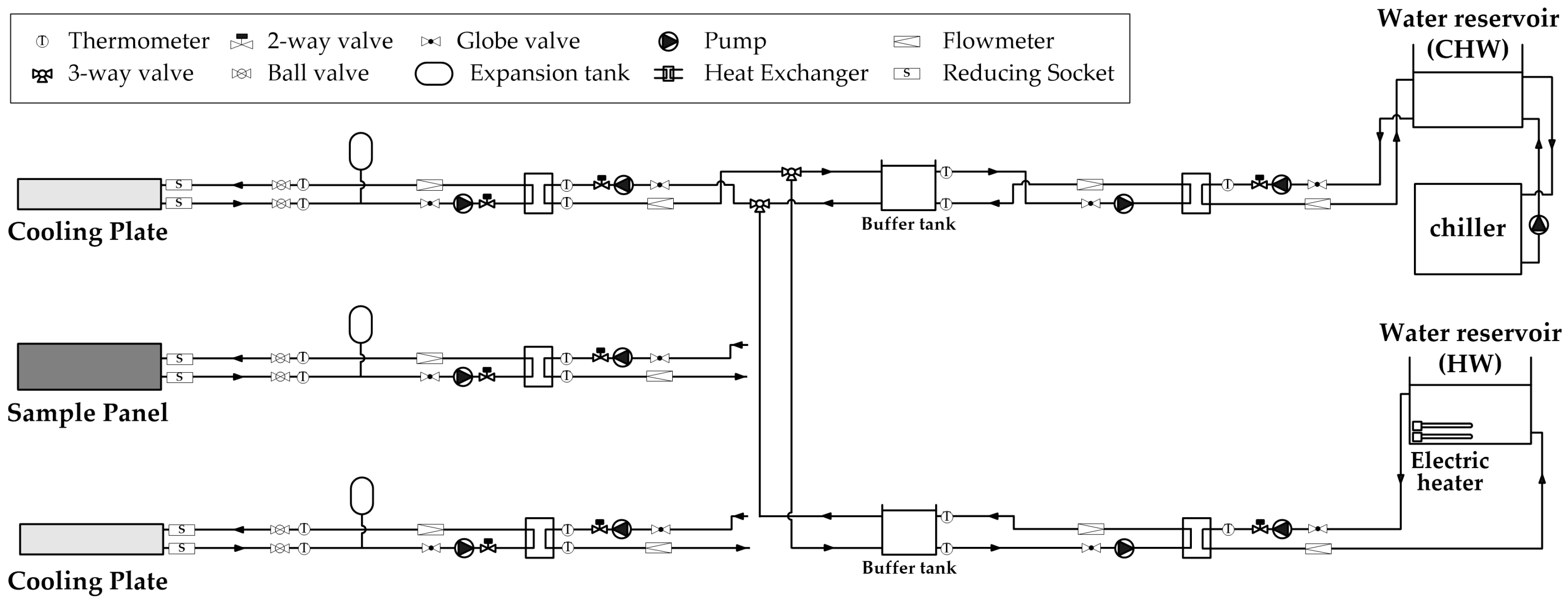
The configuration of the heat production system provides to and/or extracts heat from the sample panel and the cooling plate (Figure 7). The heat production system is configured to continuously supply water of constant temperature and flow rate to the sample panel and the cooling plate to achieve the steady-state target condition of the experiment.
The core of the configuration of the heat production system for this experiment was a buffer tank. The temperature of the water exiting the chiller significantly differed when the compressor of the chiller was running and not running. Therefore, the water temperature inside the reservoir fluctuated owing to the temperature fluctuation of the water coming out from the chiller. This fluctuation is a challenge in steady-state experiments. The heat production system is controlled to keep the temperature of the water that is supplied to the panel and the cooling plate constant. However, if the temperature of the water exiting the water tank fluctuates, the aspect of control becomes complicated and there is a possibility of divergence of control. Therefore, a buffer tank was designed to minimize the temperature deviation of the water through hardware and to facilitate the control. The buffer tank was designed to have a capacity of for the temperature difference to be within when the water in the buffer tank is well mixed, while considering the fluctuation of the water reservoir temperature and the circulating flow rate.
The control of the heat production system and the acquisition of the measurement data were performed at 5 s intervals using a cDAQ system and virtual instrument (VI) with LabView from National Instruments. The temperature was measured with a T-type thermocouple (temperature accuracy from to ), and the flow rate was measured with a turbine flow meter (flow accuracy % of reading, repeatability %) after calibration.
5. Results and Discussion
5.1. Thermal Performance Evaluation of the RFIRHP
In this study, the thermal performance of three types of RFIRHPs with different filler materials of the internal void space of the RFIRHP was compared and evaluated using the results from the experiment in which a cooling plate was used to solve the lower-part thermal insulation problem of the RFIRHP. The steady-state experiment was conducted according to the methodology of the experiment; the mean value of the measured values at each measuring point during the steady-state for over 12 h were considered as the experimental results.
As can be seen from the experimental results, all experiments satisfied the target condition that was required in the experiment (Table 2 and Table 3). In addition, under the control of the heat production system, all experiments satisfied the target condition and maintained their steady state for over 12 h. The heat balance calculation based on the experimental configuration shows that the heat balance that was removed from the upper and lower cooling plates compared to the amount of heat supplied to the sample panel satisfies the heat balance from −1.6 W to +0.9 W in all experiments (Table 3). Based on these results, it can be confirmed that the experiments in steady-state condition satisfying the target condition were correctly performed for all cases.
To evaluate the efficiency of a radiant panel, two criteria are simultaneously considered, namely the upward thermal output and the downward thermal output of the panel, for the same heat supply. When the same amount of heat is supplied to various types of radiant panels, the higher the thermal output of a panel toward the direction of the room-to-be-heated and the lower the downward thermal output, the more efficient that radiant panel will be evaluated as, and the more advantageous in terms of energy conservation it will be considered. Therefore, the EN 1264 standard recommends more than 90% efficiency of the radiant heating panel. The thermal performance of each type of RFIRHP that has been evaluated in this study was compared with all other thermal performances in terms of efficiency of the panel. The efficiency of the panel, (%), is the ratio of the thermal output to the room to be heated to the total heat supplied to the panel, and may be described using the following equation:
The values of 0.0926 and 0.1667 were used for the upper and lower surface heat transfer resistances of the RFIRHP, respectively [13]. As a result of evaluating the thermal performance of three types of RFIRHP, the efficiency of the sample panel that was not filled with a material (Alt1) was found to be the best, with an efficiency of 70.1% (Table 4). The highest efficiency of the sample panel without any filler materials at the internal void space of the RFIRHP, is attributed to the fact that the air inside the raised floor acts as an insulation that is the same as that of the still air. On the other hand, the sample panel that was filled with perlite (Alt2) was evaluated to present the lowest efficiency (61.7%) among the three considered types of sample panels. In general, perlite is a material that is used for filling of the internal void space of the raised floor, in order to improve the experience of walking. Furthermore, perlite is considered to be a heat-insulating material. However, as a result of the evaluation through this experiment, when perlite was used as a filler material for the lower insulation of the RFIRHP, the filled perlite did not demonstrate a sufficiently satisfactory performance as an insulation. In contrast, when the panel was filled with urethane foam (Alt3), the efficiency was 69.3%, which is superior compared to that of the perlite.
The efficiency of the three types of RFIRHP is less than approximately 70%, even for the panel that was not filled with a material, rated as the best among the tested sample panels. The efficiency is below the value of 90% recommended by the existing standards. The sample panel filled with urethane foam had a thermal conductivity that was expected to satisfy the recommended efficiency. Nevertheless, it did not meet the recommended value, and showed even lower efficiency compared to that of the Alt1 panel, which was not filled with a material.
The raised floor that was used for the sample panels in this experiment was spot welded at the top and at the bottom panel surfaces owing to structural problems (Figure 1b). The contact portion served as a thermal bridge to increase the downward thermal output of the panel. Therefore, it is necessary to review the design of the RFIRHP to eliminate this type of thermal bridge.
Apart from the fact that the efficiency of the panel that is recommended by the existing standards was not satisfied, there is a possibility that the downward thermal output of the RFIRHP was re-emitted to the upper part of the panel because of the interaction with the building structure below the radiant panel. Therefore, it is necessary to review the lower-part thermal insulation that is required for the RFIRHP, together with the influence of the downward thermal output on the facilities inside the raised floor.
The structure and shape of the RFIRHPs that were evaluated in this study were the same for all cases; only the filler inside the panel was different. Therefore, the structure, layers, and materials, from the hot water to the upper surface of the panel of all sample panels were the same. Nevertheless, as a result of the experiment, the upward heat transfer resistance of each panel, , presented a significant difference (Table 4). This occurred because of the uncertainty in the assembly process of each sample panel, which was due to the resistance generated at the contact surfaces between the respective layers of the panel. Even for the same radiant panels, and under the same environmental conditions, there may be differences in the thermal output due to the uncertainty that may arise in the assembly process.
This can be an issue for the mass production performed after the thermal performance evaluation of the radiant panels, since the certification and the thermal output are determined by the specifications of the product. In general, product manufacturers devote significant attention to the sample panels submitted for testing and certification, in order to get a certification with the best specifications for their products. However, in the mass production process that follows, there is a high possibility that the attention devoted to the product production will decline. There is a relatively high possibility that the prefabricated radiant panels such as RFIRHPs will differ in performance when comparing products with the same design. This is due to the uncertainty in the assembly process, as discussed above. It can be a problem if there is a difference between the specifications and the performance of the actual products. Therefore, these questions deserve special attention during the assembling and production of panels.
As one example, the upper- and lower-surface heat transfer resistances of the radiant panel (upper 0.0926 , lower 0.1667 ) [13] were added to the upward and downward heat transfer resistances of the sample panel that was filled with urethane foam (Alt3), respectively. The upper characteristic curve () and the lower characteristic curve () of the sample panel that was filled with urethane foam (Alt3) is derived as follows:
This characteristic curve can be used to design the radiant system to yield the same characteristic curve as the one calculated via the method of the existing standard. For example, if the design set temperature is assumed to be 20 , the maximum thermal output of the panel would be 97.1 based on the experimental results; thus, the maximum supply water temperature of this panel would be 32.5 , according to Equation (10). In addition, the characteristic curves can be used in the design of the radiant system, in terms of determining the maximum supply flow rate by using the upward and downward thermal output of the panel when determining the supply–return water temperature difference.
5.2. Comparison of the Results from the Modified Method and the Existing Method
In this study, the experiment was performed under the same target condition as the existing method to compare the results of the modified method with those of the existing method. Therefore, based on the results of the experiments performed in this study, we can obtain the experimental results of the existing standard by employing the existing method via Equations (2)–(4).
By adding the heat transfer resistance of the heat transfer layer (0.0985 ) that was used in the experiment to upward heat transfer resistance of the radiant panel that resulted from the modified method, it is possible to derive the same characteristic curve as that derived from the experimental results of the EN 1264 standard. Table 5 shows the gradient of the characteristic curve of the RFIRHP as derived from modified method, and the gradient of characteristic curve as calculated by employing the method of the EN 1264 standard.
By comparing the gradient of the characteristic curve that occurred from the two methods, we may observe that the gradient of the characteristic curve calculated by the existing method was 7.2–14.9% greater than that derived from the modified method. This means that the thermal performance of the radiant heating panel that was derived from the existing method is higher than the thermal performance of the radiant heating panel that was derived from the modified method by a maximum of 14.9% in the case of the panel evaluated in the present experiment.
This difference in the results is attributed to the heat transfer resistance of the heat transfer layer that was used in the experiment. In the experiment of the present study, the heat transfer resistance of the heat transfer layer was measured via the plate heat flux method prior to the main experiment for the RFIRHP, and the value was 0.0985 . Table 6 lists the results of the recalculated heat transfer resistance of the heat transfer layer of each experiment using the resulting upward thermal output of the radiant panel (), and difference between the lower surface temperature of the cooling plate () and the upper mean surface temperature of the sample panel ().
The heat transfer resistance of the heat transfer layer that was applied to each experiment was 0.0985 ; however, the recalculated heat transfer resistance of the heat transfer layer based on the experimental results was 0.1096–0.1582 . The recalculated heat transfer resistance of the heat transfer layer using the resulting experimental data is higher than the heat transfer resistance of the heat transfer layer that was applied in the experiment because of the contact resistance generated on the contact surface between the heat transfer layer and the cooling plate, and between the heat transfer layer and the sample panel.
In this study, the application of the heat transfer layer was carefully considered based on the recognition of the problem of contact resistance. In the experiment performed in this study, it was highly important to set up the experimental configuration in a manner that contact resistance of the heat transfer layer would not occur; hence, as shown in the Figure 5d, the push plate was designed and compressed with strong force in the vertical direction. Nevertheless, such contact resistance occurred.
The difference between the gradient of the characteristic curve calculated via the modified method and the gradient of the characteristic curve calculated via the existing method was caused by the difference in the heat transfer resistance of the heat transfer layer that was actually applied in each experiment. The contact resistance at the interface between the heat transfer layer and another part of the structure caused uncertainty and affected the reproducibility of the experiment recommended by the existing method. Therefore, in order to facilitate accuracy and reproducibility of the experimental results obtained by the existing methods, it is necessary to avoid the creation of interface resistance between the layers of the experimental configuration. The push plate used in this study is not sufficient for this purpose, hence alternatives should be provided, such as the application of a conductive paste/grease similar to that used in temperature sensors and heat flux plates.
To verify the repeatability and reproducibility of the modified method, additional experiments were conducted by modifying the boundary conditions of the experiment. The target conditions—except for the maximum surface temperature of the radiant panel, , of the additional experiments—were the same as those in the previous experiment. In the additional experiments, the maximum surface temperature of the radiant panel was modified from 29 to 35 , and the results are listed in Table 7, Table 8 and Table 9.
As a result of the additional experiment, the upper and lower thermal resistances of the radiant panels () and the efficiencies of the panels () were very similar to those of the previous experiment, although the boundary conditions of the experiment were changed.
The modified method proposed in this study can evaluate the downward thermal output of radiant panel, as well as render the boundary condition of the experiment more flexible than that of the existing method. In addition, the modified method showed that the experimental results were not influenced by the heat transfer resistance of the heat transfer layer, and that the repeatability and reproducibility of the experiment is ensured, whereas the existing method affects the experimental results by means of the heat transfer resistance of the heat transfer layer.
5.3. Uncertainty Analysis
Uncertainty analysis (the analysis of uncertainties in experimental measurements) is required for a proper evaluation of experimental data. In this study, uncertainty analysis is performed using the method descried by Holman [15]. Assume that the variable is a function of the independent variables , , , ⋯, . If the uncertainties in the independent variables , , , ⋯, are all given with same odds, then the uncertainty in the resulting variable is calculated by the following Equation (11):
The error analysis used to estimate the maximum uncertainty in the experimental results, was performed by using Equation (11). In this study, the temperature and flow rates were measured at 5 s intervals using appropriate instruments, as discussed previously. A mean value at each measuring points was computed by averaging the 8640 measured values, obtained during a 12 h steady-state condition, and these mean values are considered as the experimental results. Therefore, in our study, the maximum uncertainty of the experimental results is for the temperature, and 0.01% for the flow rate. We show that the maximum uncertainty has the quantity, with an acceptable uncertainty, 0.5% for , 1.2% for , and 1.2% for , respectively.
6. Conclusions
In this study, we proposed a method for the evaluation of the thermal output of radiant heating panels by employing a modification of the method that is recommended by existing standards using cooling plates to solve the problem of measuring the downward thermal output and to address the difficulty in controlling the heat transfer resistance of the heat transfer layer. By employing the modified method, the thermal performance of three types of RFIRHPs, with different filler materials for the bottom insulation of the panel, was compared and evaluated.
As a result of evaluating the thermal performance of three types of RFIRHPs, the efficiency of the sample panel that was not filled with a material was found to be the best, with an efficiency of 70.1%. Based on the results, we proposed additional points to be considered in the current design to improve the thermal performance of the RFIRHP. Moreover, to improve the thermal performance of radiant panels, such as the RFIRHP, we mentioned certain points to be taken into consideration during the assembly process of radiant panels.
In addition, the experimental results were calculated via the existing method, and the effectiveness of the modified method was confirmed by comparing the results from the existing method with the results obtained from the modified method. The modified method that was proposed in this study showed that the experimental results were not influenced by the heat transfer resistance of the heat transfer layer, and the repeatability and reproducibility of the experiment is ensured, whereas the existing method affects the experimental results by means of the heat transfer resistance of the heat transfer layer.
Acknowledgments
This research was supported by Basic Science Research Program through the National Research Foundation of Korea (NRF) funded by the Ministry of Education (NRF-2015R1D1A1A09061467).
Author Contributions
Dong-Woo Kim and Kwang-Woo Kim conceived and designed the experiments; Dong-Woo Kim and Sang-Hoon Park performed the experiments; Dong-Woo Kim, Goo-Sang Joe, and Sang-Hoon Park analyzed the data; Dong-Woo Kim wrote the paper; Myoung-Souk Yeo and Kwang-Woo Kim supervised the paper writing.
Conflicts of Interest
The authors declare no conflict of interest.
Abbreviations
The following abbreviations are used in this manuscript:
| RFIRHP | Raised Floor Integrated Radiant Heating Panel |
References
- Yeo, M.S.; Yang, I.H.; Kim, K.W. Historical changes and recent energy saving potential of residential heating in Korea. Energy Build. 2003, 35, 715–727. [Google Scholar] [CrossRef]
- Zhuang, Z.; Li, Y.; Chen, B.; Guo, J. Chinese kang as a domestic heating system in rural northern China—A review. Energy Build. 2009, 41, 111–119. [Google Scholar] [CrossRef]
- Bean, R.; ArchD, K.W.K. Part 1: History of Radiant Heating & Cooling Systems. ASHRAE J. 2010, 52, 40. [Google Scholar]
- Bean, R.; ArchD, K.W.K. Part 2: History of Radiant Heating & Cooling Systems. ASHRAE J. 2010, 52, 50. [Google Scholar]
- Olesen, B.W. Radiant floor heating in theory and practice. ASHRAE J. 2002, 44, 19. [Google Scholar]
- Rhee, K.; Yeo, M.; Kim, K. Development of an emulation method for the performance evaluation of radiant floor heating systems. Build. Serv. Eng. Res. Technol. 2014, 35, 488–506. [Google Scholar] [CrossRef]
- Comité Européen de Normalisation (CEN). Water Based Surface Embedded Heating and Cooling Systems—Part 2: Floor Heating: Prove Methods for the Determination of the Thermal Output Using Calculation and Test Methods; Standard EN 1264-2; Comité Européen de Normalisation: Brussels, Belgium, 2012. [Google Scholar]
- Nordic. Floor Heating Systems: Design and Type Testing of Waterborne Heat Systems for Lightweight Structures; NT VVS 127; Nordic: Oslo, Norway, 2001. [Google Scholar]
- ASHRAE. 2016 ASHRAE Handbook—HVAC Systems and Equipment, Ch.6 Radiant Heating and Cooling; American Society of Heating, Refrigerating and Air-Conditioning Engineers: Atlanta, GA, USA, 2016. [Google Scholar]
- International Organization for Standardization (ISO). Building Environment Design—Design, Dimensioning, Installation and Control of Embedded Radiant Heating and Cooling Systems—Part 2: Determination of the Design Heating and Cooling Capacity; Standard ISO 11855-2; International Organization for Standardization: Geneva, Switzerland, 2012. [Google Scholar]
- Shin, D.U.; Shin, M.S.; Rhee, K.N.; Ryu, S.R.; Jeong, C.H.; Yeo, M.S.; Kim, K.W. The thermal output evaluation of radiant heating panels by experiment. Build. Serv. Eng. Res. Technol. 2015, 36, 580–595. [Google Scholar] [CrossRef]
- Weitzmann, P.; Svendsen, S. Method for calculating thermal properties of lightweight floor heating panels based on an experimental setup. Int. J. Low Energy Sustain. Build. 2005, 3, 1–15. [Google Scholar]
- Babiak, J.; Olesen, B.W.; Petras, D. Low Temperature Heating and High Temperature Cooling: REHVA Guidebook No. 7; Federation of European Heating, Ventilation and Air Conditioning Associations: Brussels, Belgium, 2007. [Google Scholar]
- Korea Standard Association (KSA). Test Methods for Thermal Transmission Properties of Thermal Insulations; Standard KS L 2016; Korea Standard Association: Seoul, Korea, 2012. [Google Scholar]
- Holman, J.P. Experimental Methods for Engineers; McGraw-Hill: New York, NY, USA, 2012; Volume 8. [Google Scholar]
Figure 1.
Example of the RFIRHP (① is finishing material, ② is top plate, ③ is water pipe, ④ is heat transfer plate, ⑤ is internal void space, and ⑥ is bottom plate): (a) Layers. (b) Cross section.
Figure 1.
Example of the RFIRHP (① is finishing material, ② is top plate, ③ is water pipe, ④ is heat transfer plate, ⑤ is internal void space, and ⑥ is bottom plate): (a) Layers. (b) Cross section.
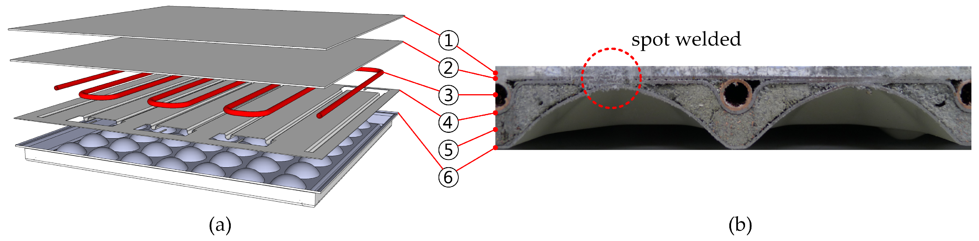
Figure 2.
Heat transfer resistances involved in the heat transfer from the hot water to the room around the radiant panel, and classification of their characteristics.
Figure 2.
Heat transfer resistances involved in the heat transfer from the hot water to the room around the radiant panel, and classification of their characteristics.
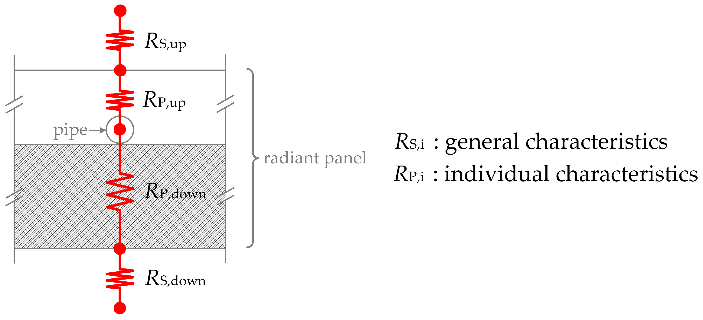
Figure 3.
Configuration with target condition based on the EN 1264 Standard.

Figure 4.
Factors related to the heat flux in the experimental configuration and the heat balance thereof in the steady-state experiment, using the modified method. (in steady-state condition, , , and ).
Figure 4.
Factors related to the heat flux in the experimental configuration and the heat balance thereof in the steady-state experiment, using the modified method. (in steady-state condition, , , and ).
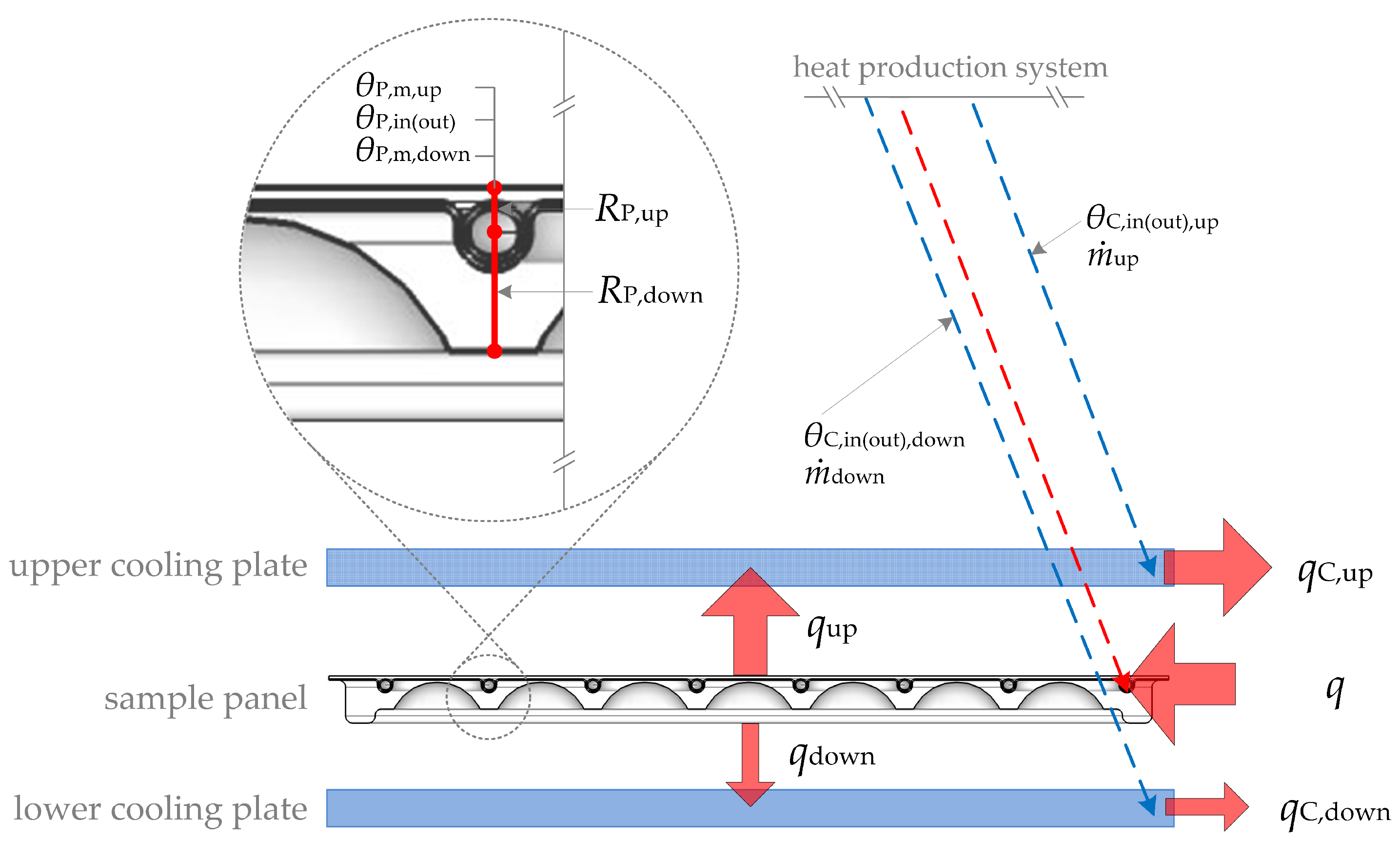
Figure 5.
Experimental setup: (a) Plan view of the completed experimental setup. (b) Section view of the completed experimental setup. (c) Experimental setup prior to insulation closures. (d) The completed experimental setup used in this study.
Figure 5.
Experimental setup: (a) Plan view of the completed experimental setup. (b) Section view of the completed experimental setup. (c) Experimental setup prior to insulation closures. (d) The completed experimental setup used in this study.
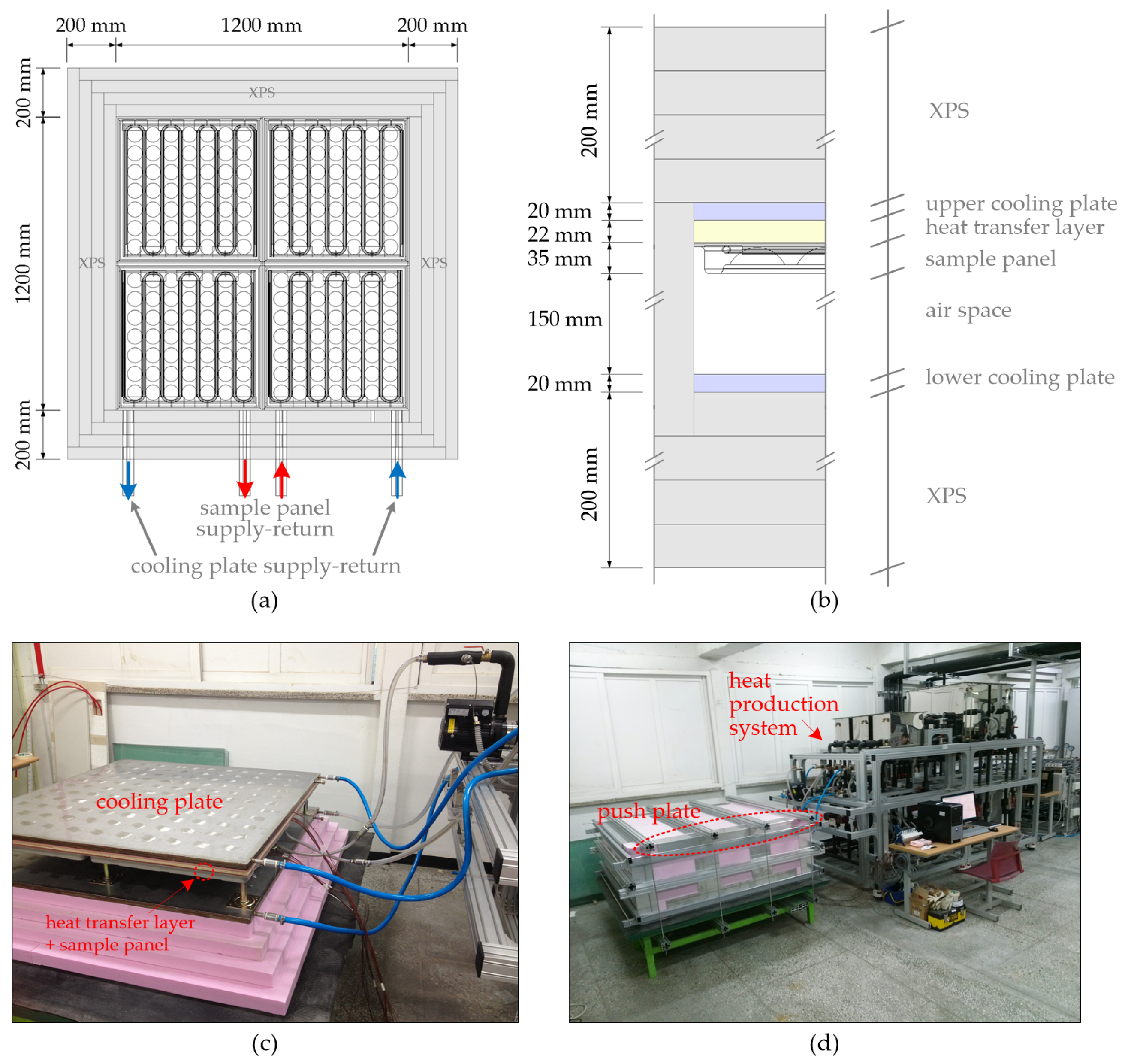
Figure 6.
Determination of the position of the thermocouple for the measurements of : (a) Schematic of the measurement of . (b) The curved piping of a RFIRHP is replaced by a straight one. (c) The shape of a RFIRHP where the half of cell is repeated. (d) The position of the thermocouple in the measurements of .
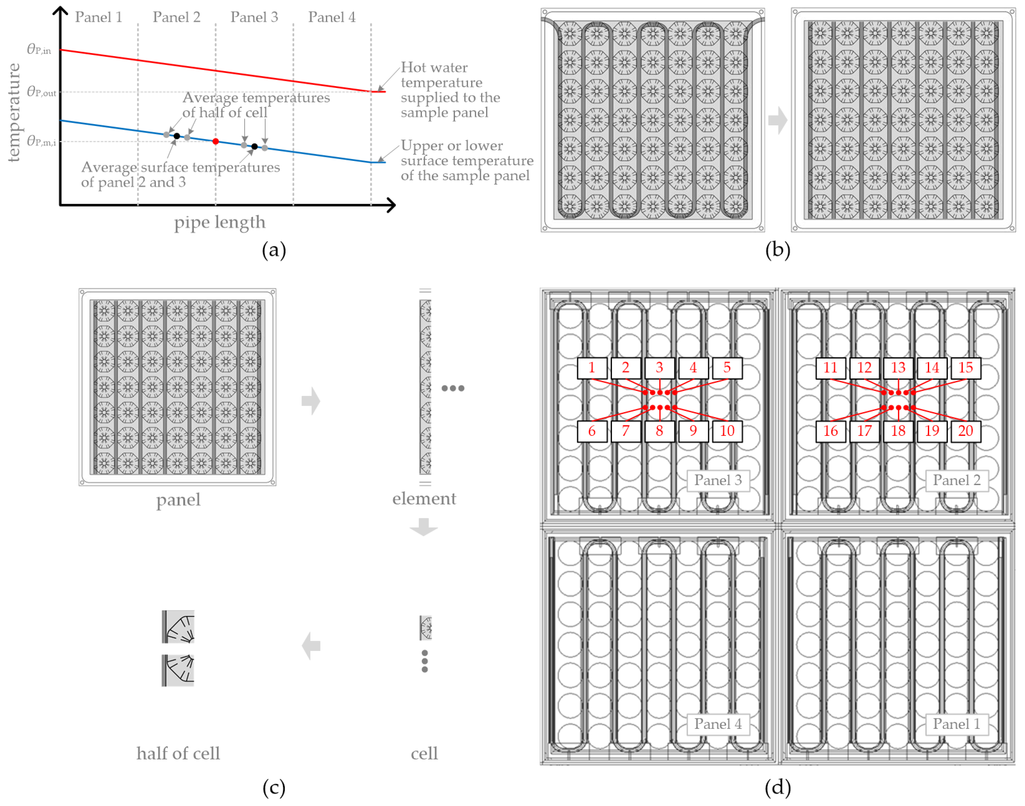
Figure 7.
The configuration of the heat production system and the hydraulic piping.

Table 1.
Three types of fillers used in the internal air gap of the RFIRHP and their thermal conductivity.
Table 1.
Three types of fillers used in the internal air gap of the RFIRHP and their thermal conductivity.
| Case | Filler Type | Thermal Conductivity of Filler () |
|---|---|---|
| Alt1 | None | - |
| Alt2 | Perlite | ∼0.062 |
| Alt3 | Urethane foam | ∼0.019 |
Table 2.
Experimental results of surface temperature.
| Test | () | () | () | () | () | () |
|---|---|---|---|---|---|---|
| Alt1 | 29.00 | 20.00 | 28.77 | 29.18 | 2.88 | 2.46 |
| Alt2 | 29.01 | 20.00 | 28.91 | 29.76 | 1.79 | 0.94 |
| Alt3 | 29.00 | 20.01 | 28.73 | 28.50 | 1.35 | 1.59 |
Table 3.
Experimental results of the supply–return water temperature and flow rate, and of the heat balance.
Table 3.
Experimental results of the supply–return water temperature and flow rate, and of the heat balance.
| Test | () | () | () | () | () | q () | Heat Balance (W) | |
|---|---|---|---|---|---|---|---|---|
| Alt1 | Sample Panel | 31.89 | 31.41 | 0.47 | 0.0710 | 4178 | 139.9 (97.1) | −1.6 |
| Upper cooling plate | 18.77 | 19.05 | 0.28 | 0.0986 | 4182 | 115.1 (80.0) | ||
| Lower cooling plate | 18.89 | 18.98 | 0.09 | 0.0663 | 4182 | 26.3 (18.3) | ||
| Alt2 | Sample Panel | 30.89 | 30.53 | 0.36 | 0.0821 | 4178 | 122.3 (84.9) | +0.9 |
| Upper cooling plate | 17.98 | 18.20 | 0.23 | 0.0850 | 4182 | 81.1 (56.3) | ||
| Lower cooling plate | 17.96 | 18.11 | 0.15 | 0.0646 | 4182 | 40.3 (28.0) | ||
| Alt3 | Sample Panel | 30.26 | 29.92 | 0.34 | 0.0764 | 4178 | 108.4 (75.2) | −0.1 |
| Upper cooling plate | 18.68 | 19.01 | 0.33 | 0.0612 | 4182 | 84.3 (58.6) | ||
| Lower cooling plate | 18.76 | 18.85 | 0.09 | 0.0646 | 4182 | 24.1 (16.7) | ||
Table 4.
Calculation results of the upward and downward thermal resistance of the sample panel and of their efficiency.
Table 4.
Calculation results of the upward and downward thermal resistance of the sample panel and of their efficiency.
| Test | () | () | (%) |
|---|---|---|---|
| Alt1 | 0.0360 | 0.1345 | 70.1 |
| Alt2 | 0.0318 | 0.0335 | 61.7 |
| Alt3 | 0.0231 | 0.0949 | 69.3 |
Table 5.
Gradient of the characteristic curve calculated via the two methods.
| Test | () | % Diff. | |
|---|---|---|---|
| Modified Method | EN 1264 | ||
| Alt1 | 7.78 | 8.34 | +7.2 |
| Alt2 | 8.04 | 9.24 | +14.9 |
| Alt3 | 8.64 | 9.58 | +10.9 |
Table 6.
Recalculated heat transfer resistance of the heat transfer layer of each experiment.
| Test | () |
|---|---|
| Alt1 | 0.1096 |
| Alt2 | 0.1582 |
| Alt3 | 0.1489 |
Table 7.
Experimental result of surface temperature (additional experiment).
| Test | () | () | () | () | () | () |
|---|---|---|---|---|---|---|
| Alt1 | 35.00 | 20.00 | 34.53 | 35.26 | 4.72 | 3.99 |
| Alt2 | 35.01 | 20.00 | 34.94 | 36.27 | 3.01 | 1.68 |
| Alt3 | 35.00 | 20.03 | 34.71 | 34.43 | 2.35 | 2.64 |
Table 8.
Experimental result of the supply–return water temperature and flow rate and of the heat balance (additional experiment).
Table 8.
Experimental result of the supply–return water temperature and flow rate and of the heat balance (additional experiment).
| Test | () | () | () | () | () | q () | Heat Balance (W) | |
|---|---|---|---|---|---|---|---|---|
| Alt1 | Sample Panel | 39.43 | 39.07 | 0.37 | 0.1369 | 4179 | 210.4 (146.1) | −4.9 |
| Upper cooling plate | 18.42 | 18.61 | 0.19 | 0.2193 | 4182 | 177.4 (123.2) | ||
| Lower cooling plate | 18.50 | 18.61 | 0.11 | 0.0833 | 4182 | 38.0 (26.4) | ||
| Alt2 | Sample Panel | 38.13 | 37.77 | 0.35 | 0.1394 | 4178 | 206.1 (143.1) | |
| Upper cooling plate | 17.02 | 17.29 | 0.26 | 0.1207 | 4184 | 133.0 (92.4) | ||
| Lower cooling plate | 16.99 | 17.36 | 0.37 | 0.0476 | 4184 | 74.1 (51.4) | ||
| Alt3 | Sample Panel | 37.27 | 36.88 | 0.39 | 0.1099 | 4178 | 179.3 (124.5) | 1.9 |
| Upper cooling plate | 18.29 | 18.59 | 0.30 | 0.1088 | 4183 | 136.2 (94.6) | ||
| Lower cooling plate | 18.30 | 18.44 | 0.15 | 0.0680 | 4183 | 41.3 (28.7) | ||
Table 9.
Calculation results of upper and lower thermal resistances of the sample panel and their efficiency (additional experiment).
Table 9.
Calculation results of upper and lower thermal resistances of the sample panel and their efficiency (additional experiment).
| Test | () | () | (%) |
|---|---|---|---|
| Alt1 | 0.0383 | 0.1512 | 70.8 |
| Alt2 | 0.0325 | 0.0326 | 61.4 |
| Alt3 | 0.0249 | 0.0921 | 68.8 |
© 2017 by the authors. Licensee MDPI, Basel, Switzerland. This article is an open access article distributed under the terms and conditions of the Creative Commons Attribution (CC BY) license (http://creativecommons.org/licenses/by/4.0/).
Share and Cite
MDPI and ACS Style
Kim, D.-W.; Joe, G.-S.; Park, S.-H.; Yeo, M.-S.; Kim, K.-W. Experimental Evaluation of the Thermal Performance of Raised Floor Integrated Radiant Heating Panels. Energies 2017, 10, 1632. https://doi.org/10.3390/en10101632
AMA Style
Kim D-W, Joe G-S, Park S-H, Yeo M-S, Kim K-W. Experimental Evaluation of the Thermal Performance of Raised Floor Integrated Radiant Heating Panels. Energies. 2017; 10(10):1632. https://doi.org/10.3390/en10101632
Chicago/Turabian StyleKim, Dong-Woo, Goo-Sang Joe, Sang-Hoon Park, Myoung-Souk Yeo, and Kwang-Woo Kim. 2017. "Experimental Evaluation of the Thermal Performance of Raised Floor Integrated Radiant Heating Panels" Energies 10, no. 10: 1632. https://doi.org/10.3390/en10101632
Note that from the first issue of 2016, this journal uses article numbers instead of page numbers. See further details here.