
Influence Line-Based Design of Scissors-Type Bridge

 ,
,
Abstract
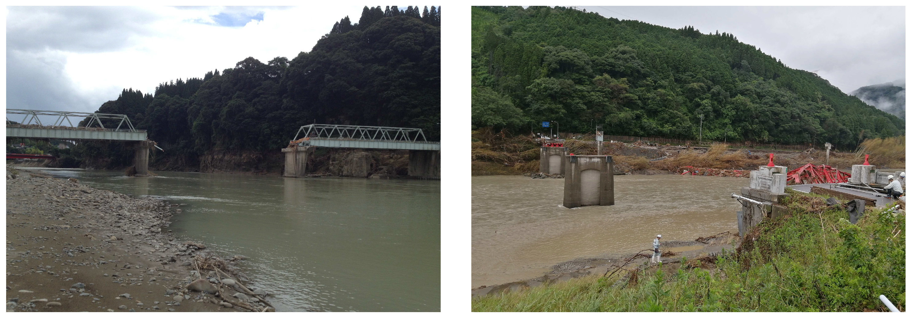
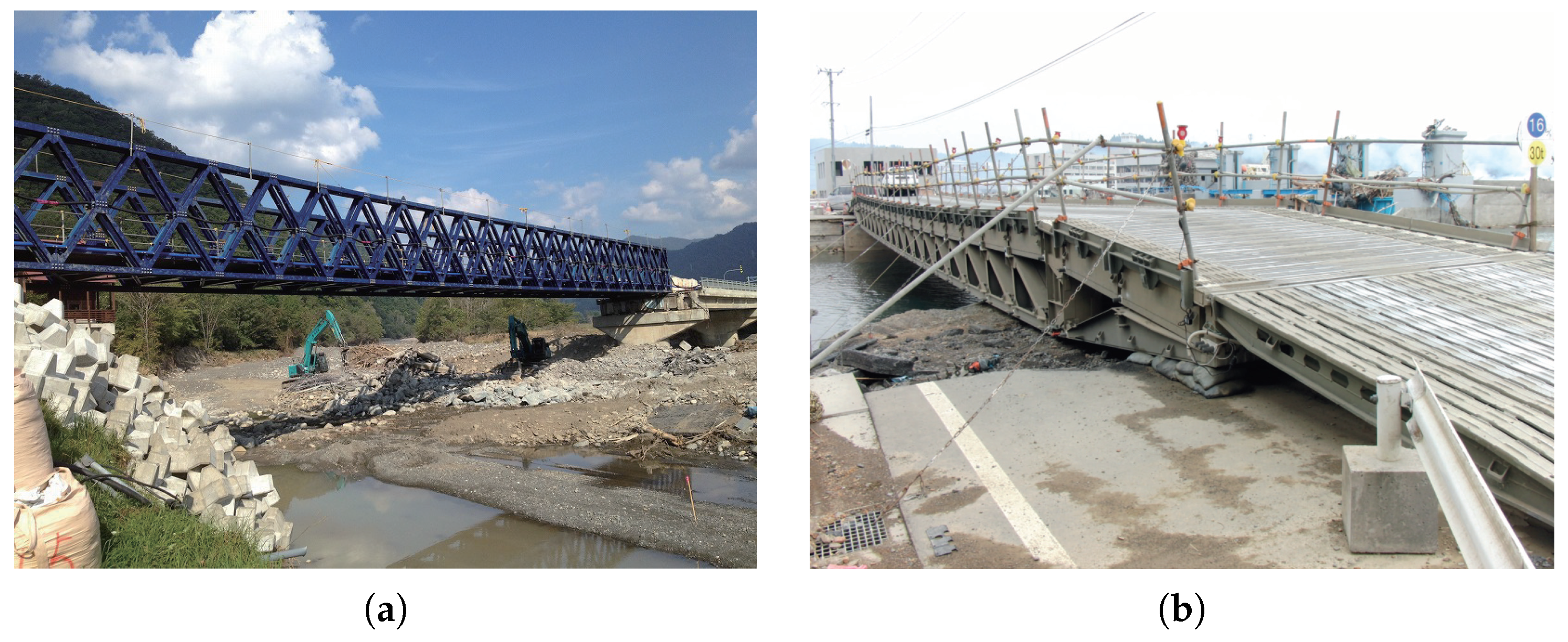
1. Introduction

2. The Equilibrium Theory
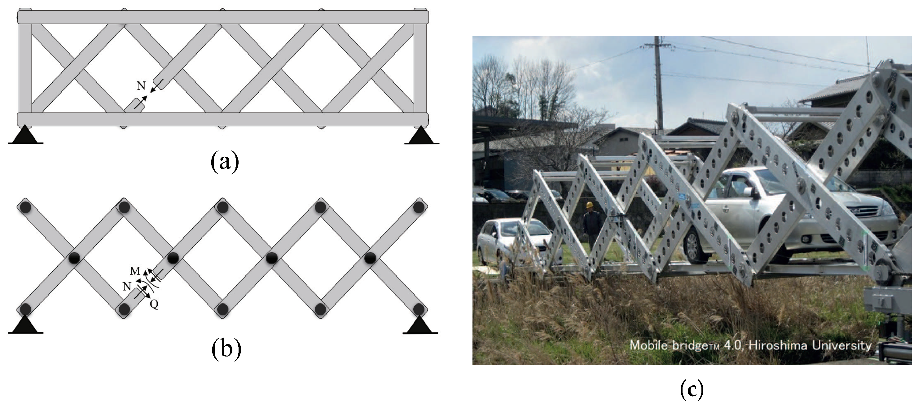
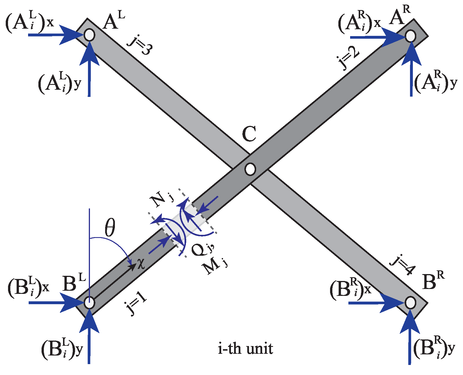
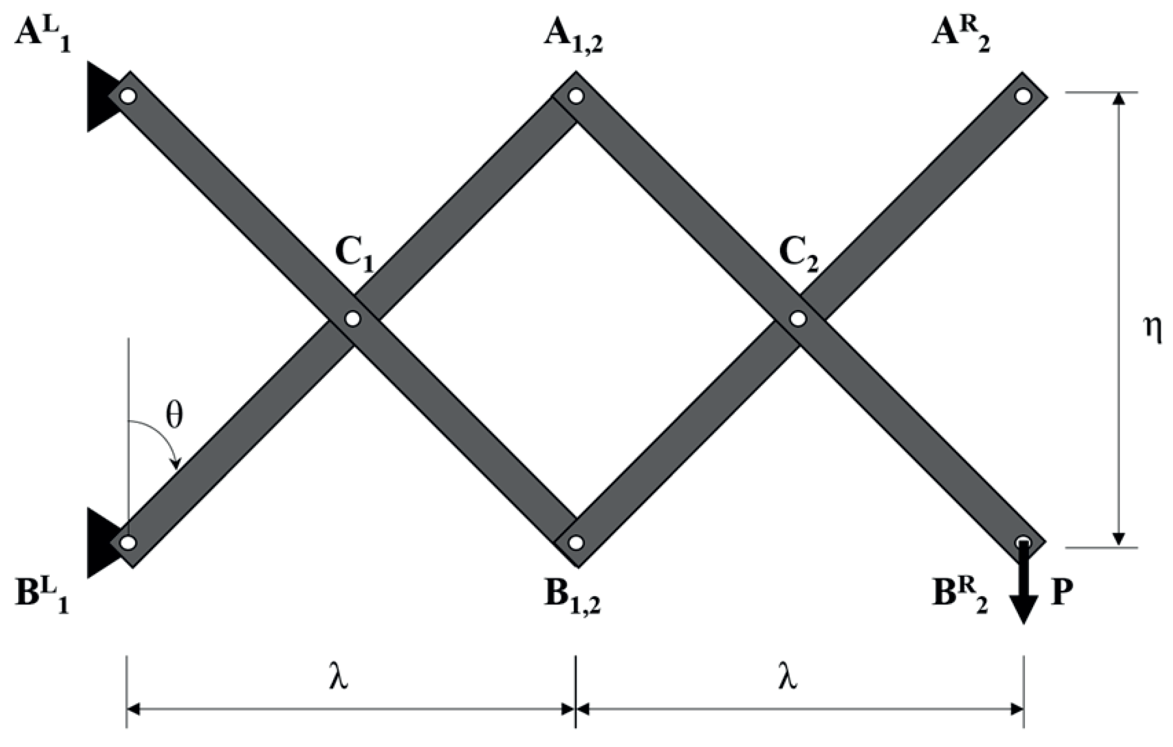
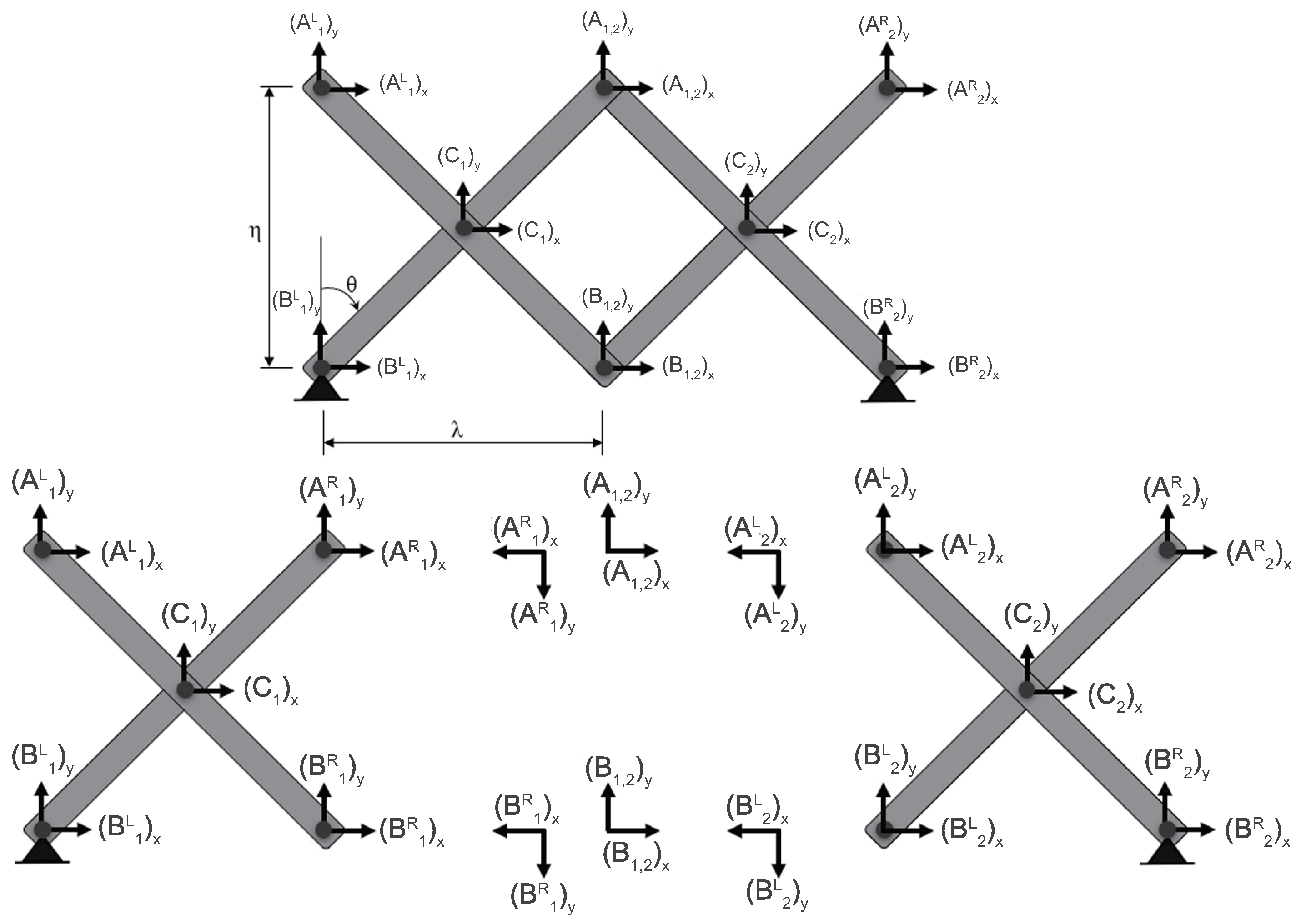
2.1. The Mechanism of the Scissors Structure Using the Cantilever Model
2.2. The Mechanism of Scissors Structure Using Simple Support Model
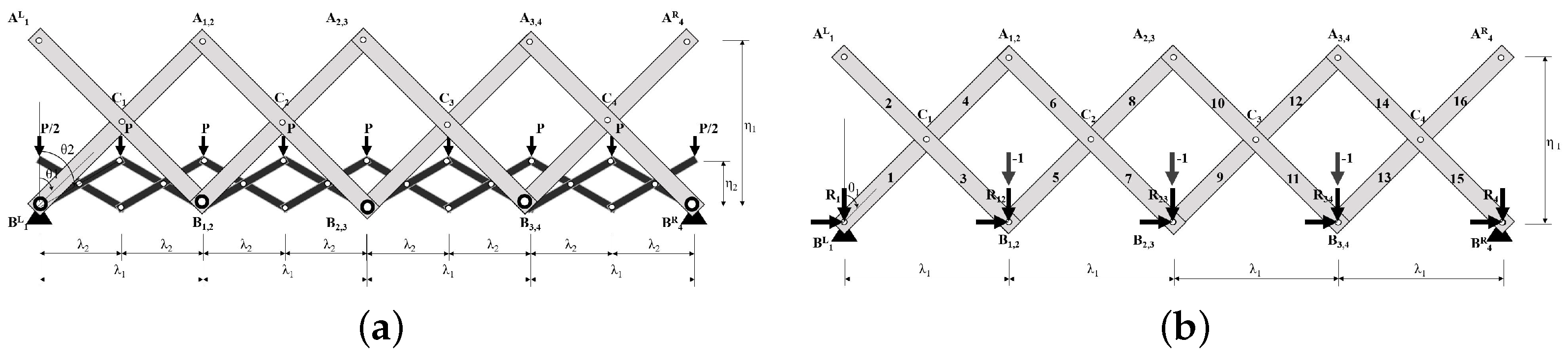
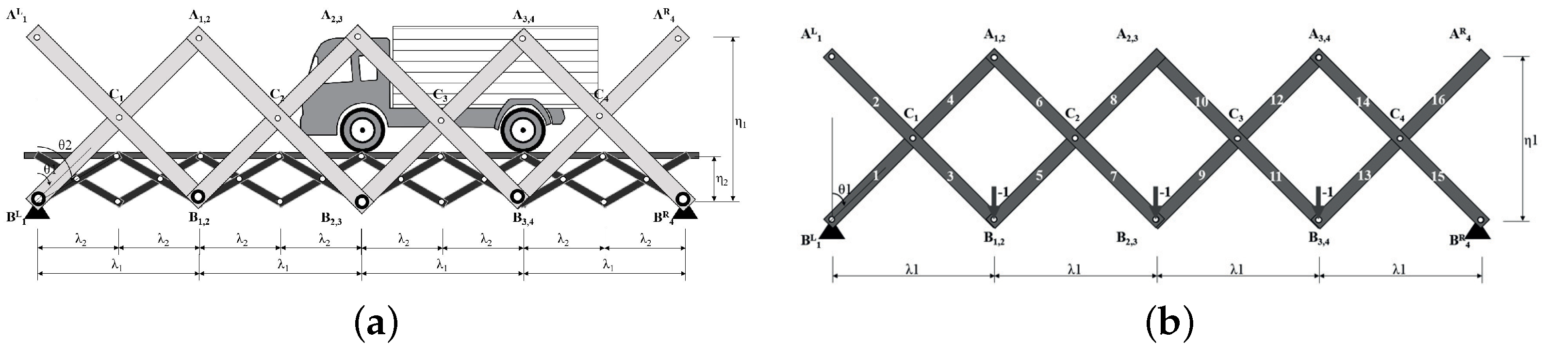
3. Scissors Bridge Design Method
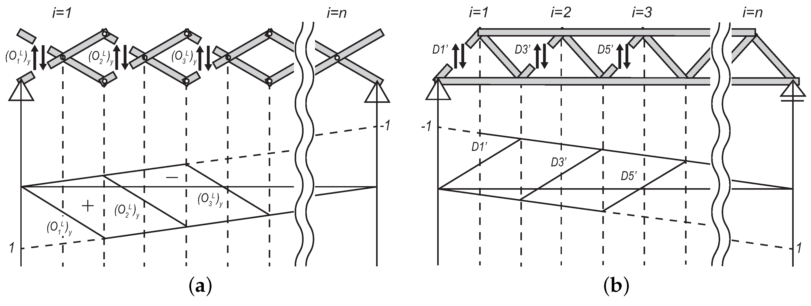
3.1. Comparison with the Influence Line (I.L.) of a Truss
3.2. Design Method Using Influence Line (I.L.)
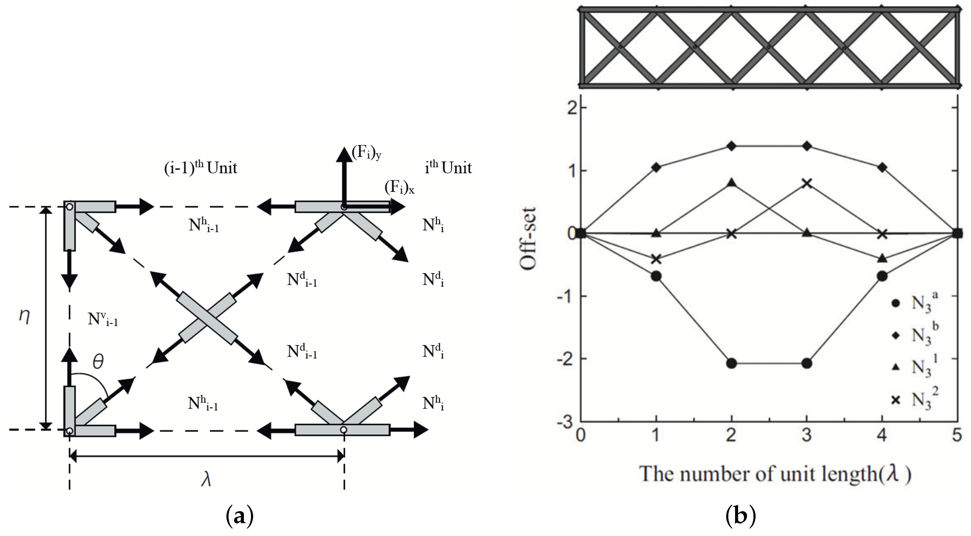
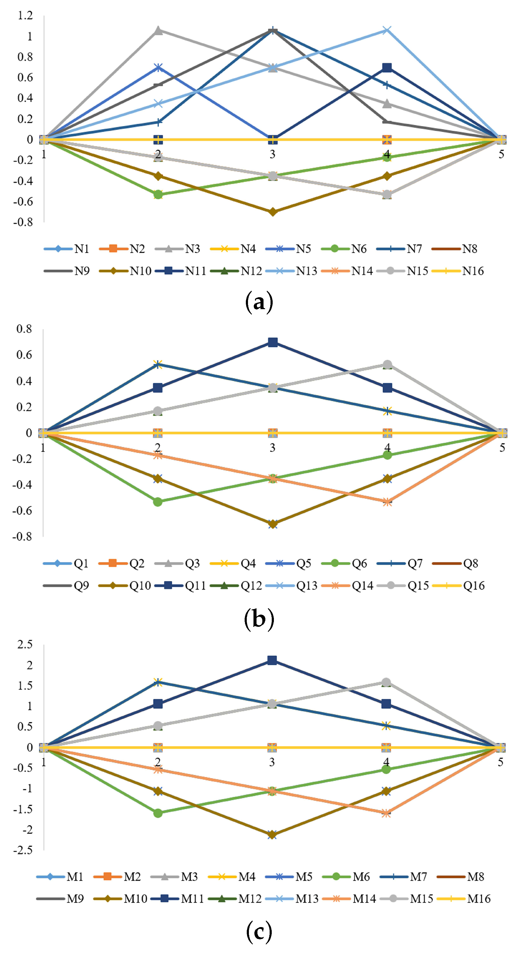
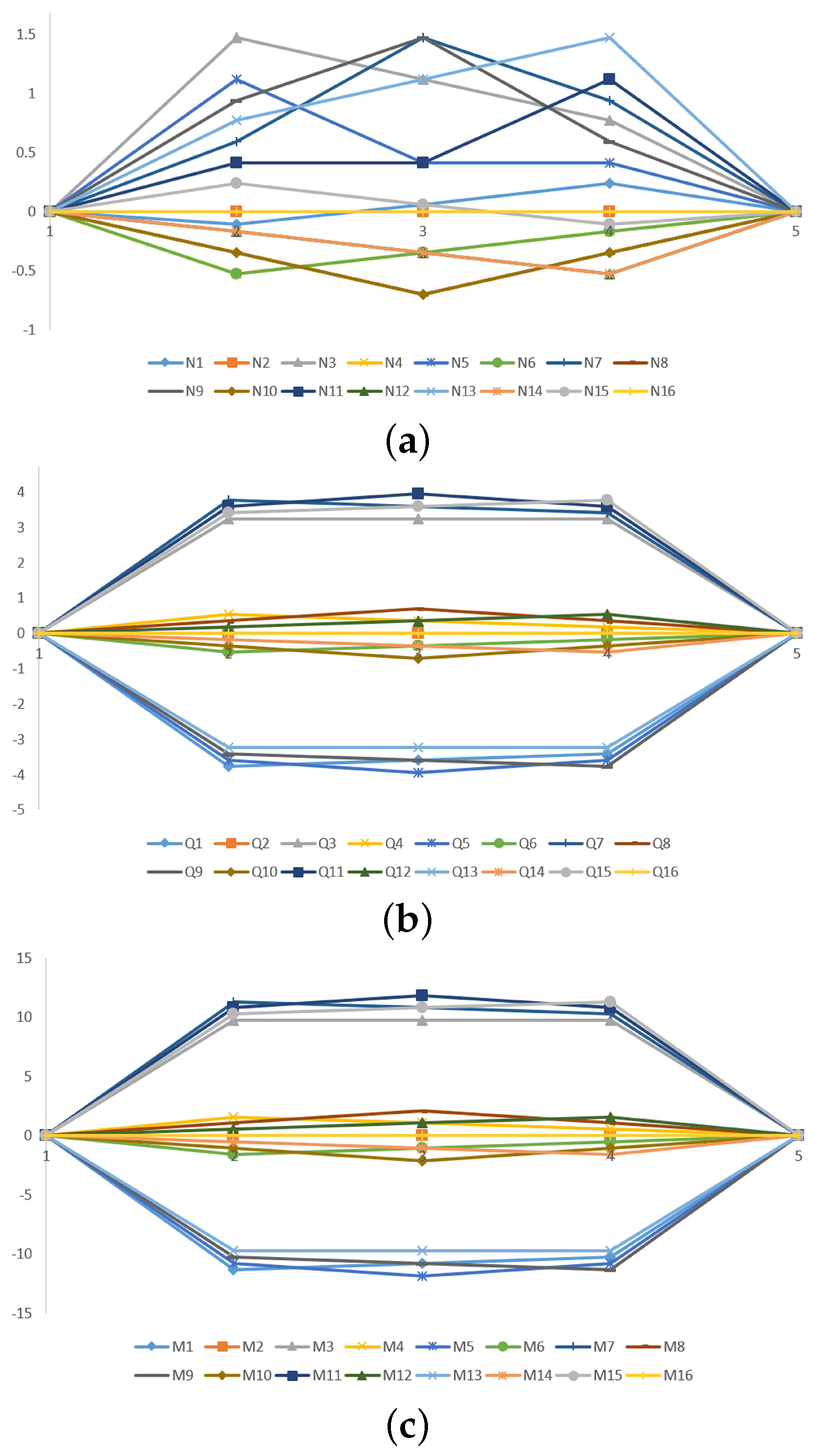
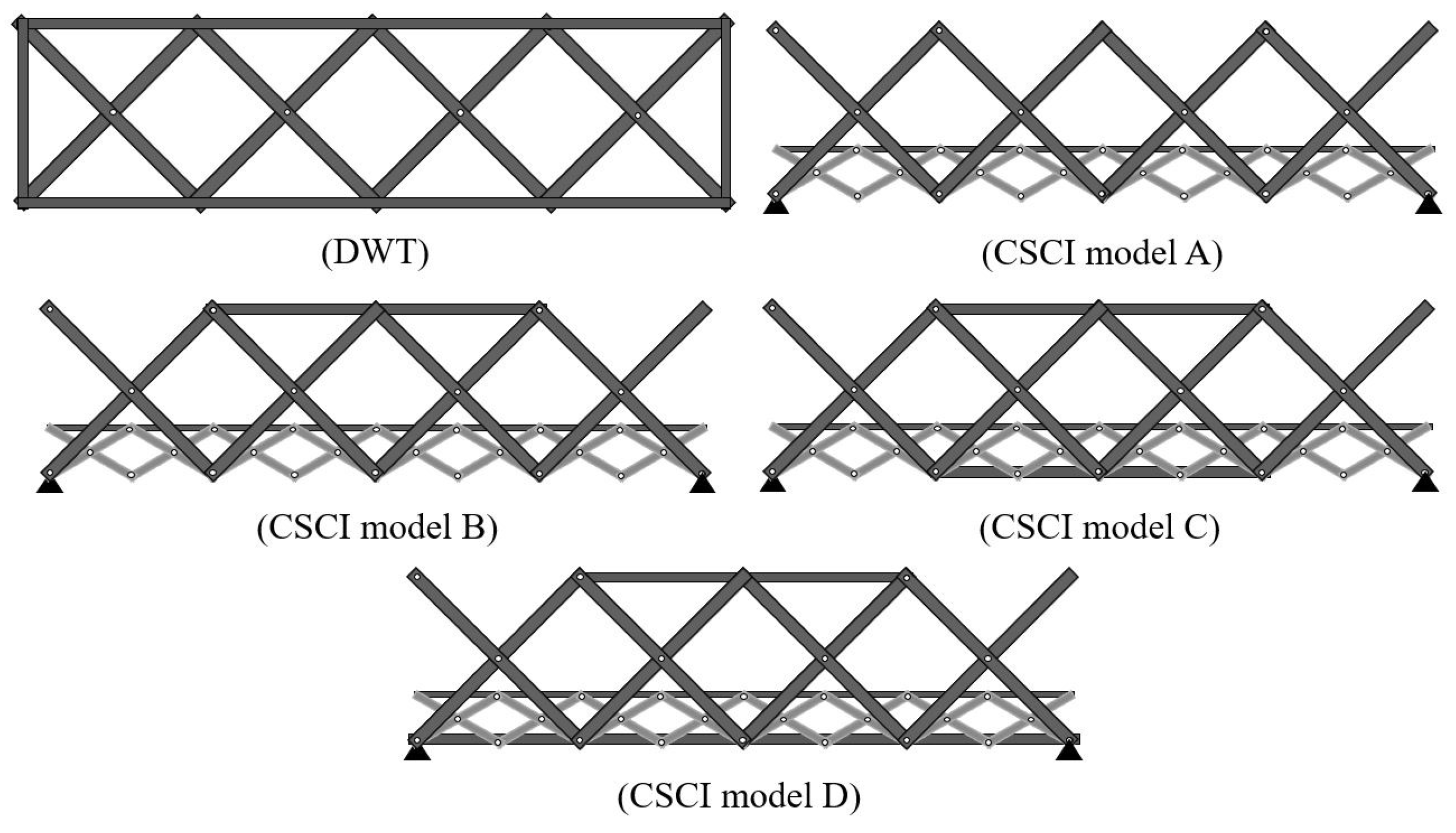
4. The Influence Line of Scissors and Double-Warren Truss Structures
4.1. I.L. of DWT Structure
4.2. I.L. of CSCI Structure
4.3. Results and Discussions
5. Conclusions
- Using the equilibrium mechanics theory of the SCI, we obtained the equations of the primary I.L.s of the sectional forces of the frame elements with pin-connections. Furthermore, their I.L. has been used to design the maximum loading point of a structure by the equilibrium equations and the assumed loading from the small SCI to the main SCI.
- The authors numerically analyzed the CSCI structure, resulting in a normal SCI structure that is used currently.
- The I.L. at which the axial force N is higher than unit at 2nd, 3rd, 4th nodal points, is 1.1 unit (+10%); Shear force Q is lower than unit at 3rd nodal point, the I.L. is 0.7 unit (−30%); Bending moment M is higher than unit at 3rd nodal point, the I.L is 2.2 unit (+120%).
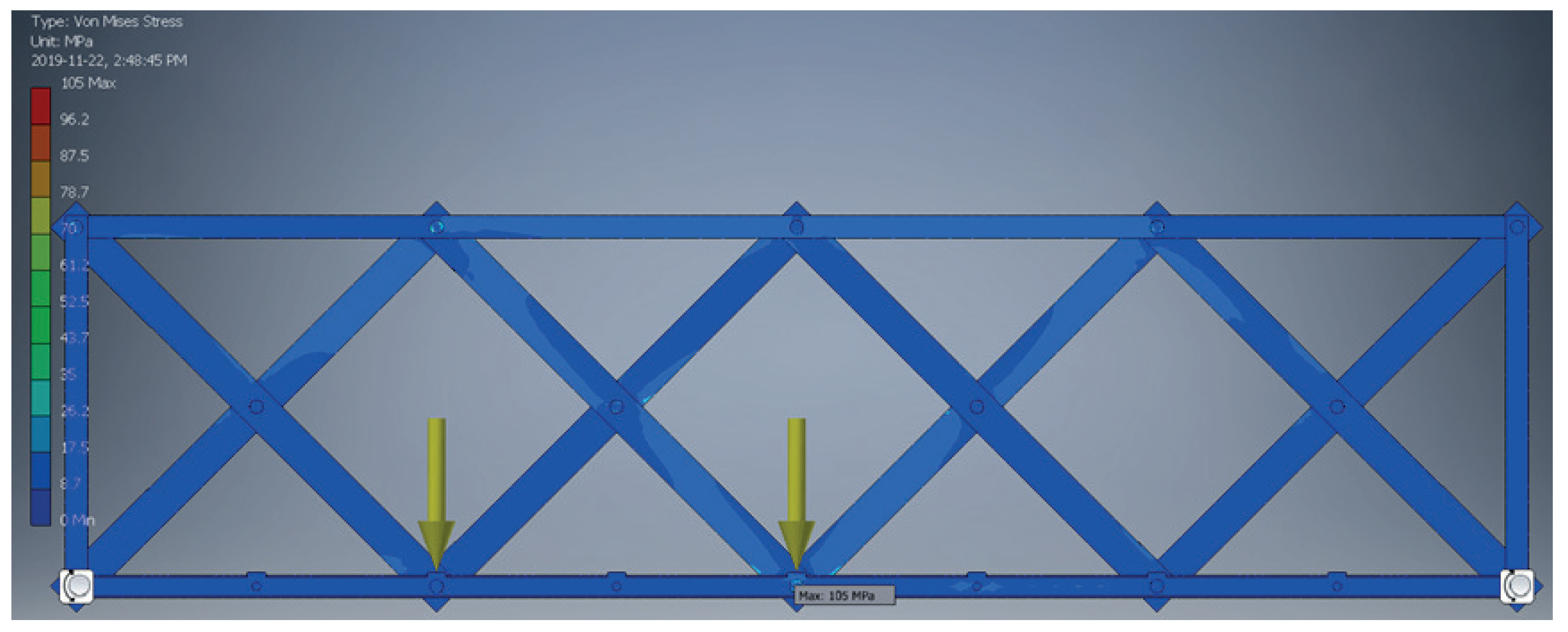
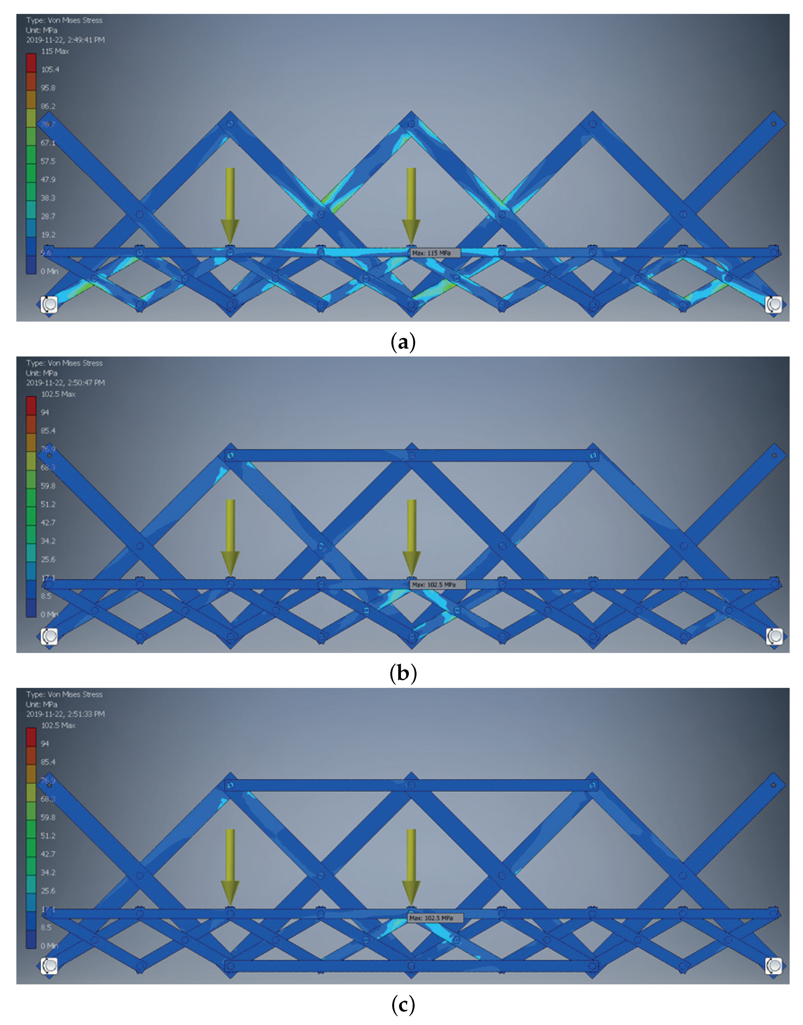
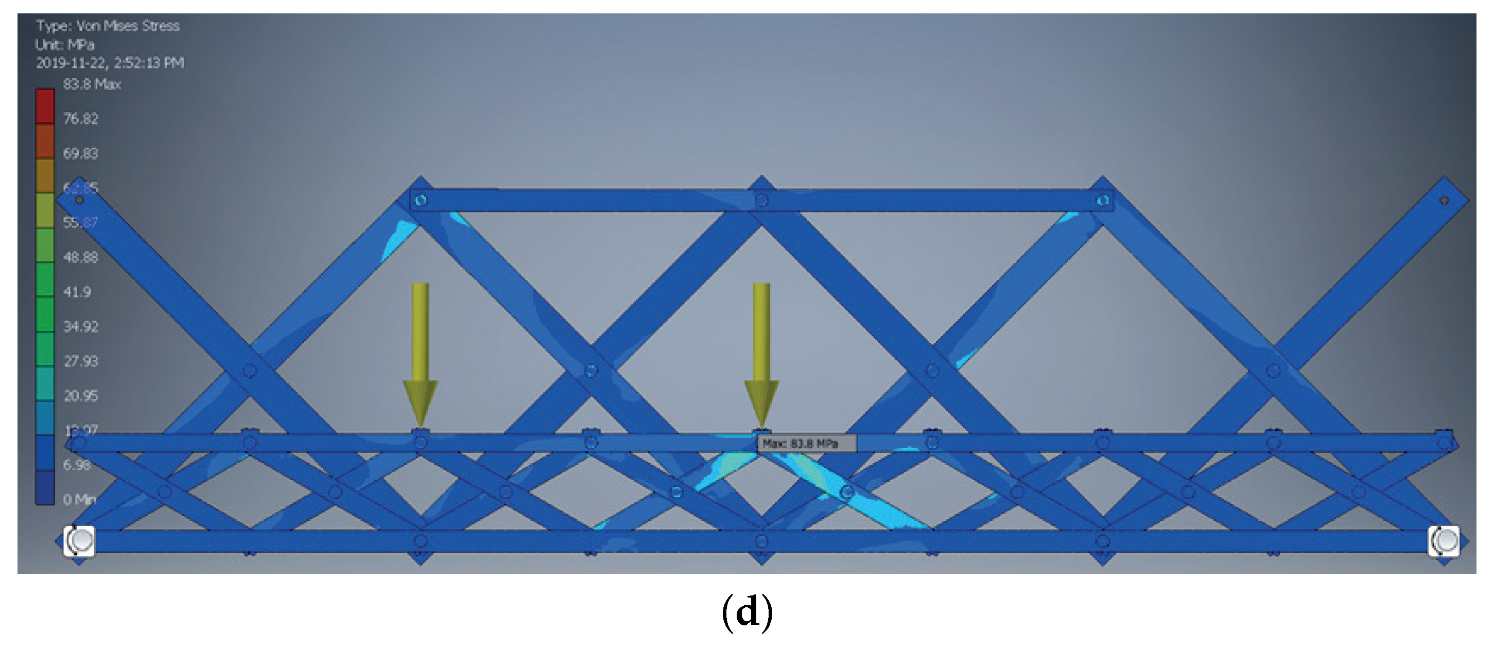
- A comparison between the stress of DWT and CSCI structure showed that the stress of CSCI (A) is greater than DWT by 10%, while the stress of CSCI (B) is lower than DWT by 2%, but displacement is only over 10%. Moreover, in the case where the comparative model is CSCI (A), we can observe that the CSCI (B) clearly shows potential that when upper reinforcement member is applied, the stress reduces by 11%, while the mass increases by only 8%.
Author Contributions
Funding
Institutional Review Board Statement
Informed Consent Statement
Data Availability Statement
Conflicts of Interest
References
- Ario, I.; Yamashita, T.; Tsubaki, R.; Kawamura, S.; Uchida, T.; Watanabe, G.; Fujiwara, A. Investigation of Bridge Collapse Phenomena due to Heavy Rain Floods: Structural, Hydraulic, and Hydrological Analysis. J. Bridge Eng. 2022, 27, 04022073. [Google Scholar] [CrossRef]
- Ario, I.; Watanabe, G.; Shibata, T.; Kaita, T.; Kawamura, S. Investigation Report Damage Survey of Bridge Collapse Phenomena in Misasa River Due to Torrential Rain in Western Japan Flood in 2018. Academic Research Repository in Hiroshima University. 2022, pp. 1–35. Available online: https://ir.lib.hiroshima-u.ac.jp/files/public/5/52397/20220607153724188335/0606a-Hiroshima-broken-bridges2018-2g.pdf (accessed on 10 August 2022).
- Ario, I. Structure with the Expanding and Folding Equipment in Hiroshima University. Japan Patent No. 2006-037668, 15 February 2006. [Google Scholar]
- Production Information of KD Bridge Wtruss. Available online: http://www.hirose-net.com/pdf/catalog/07.pdf (accessed on 10 August 2022).
- WFEL Ltd. Dry Support Bridge. Available online: https://www.wfel.com/project/dry-support-bridge (accessed on 10 August 2022).
- Unibridge Company. Emergency Bridges of Unibridge. Available online: http://www.unibridge.net.au/solution/emergency-bridges/ (accessed on 10 August 2022).
- Wight, R.; Erki, M.; Shyu, C.; Tanovic, R.; Heffernan, P. Development of FRP Short-Span Deployable Bridge—Experimental Results. J. Bridge Eng. 2006, 11, 489–498. [Google Scholar] [CrossRef]
- Perez, P.E. Three Dimensional Reticular Structure. U.S. Patent NO. 3185164, 25 May 1965. Available online: https://patents.google.com/patent/US3185164A/en (accessed on 10 August 2022).
- Zeigler, T.R. Collapsible Self-Supporting Structure. U.S. Patent No. 3968808, 13 July 1976. Available online: https://patents.google.com/patent/US3968808A/en (accessed on 10 August 2022).
- Escrig, F. Expandable space structure. Int. J. Space Struct. 1985, 1, 79–91. [Google Scholar] [CrossRef]
- Ario, I.; Chikahiro, Y. A new type of bridge mobilebridge registered to super-quickly recover a bridge. World J. Eng. Technol. 2015, 3, 170. [Google Scholar] [CrossRef]
- Harris, M.F. Stress Balanced Extendible Boom Structure. U.S. Patent No. 3877544, 15 April 1975. [Google Scholar]
- Kwan, A.; Pellegrino, S. Matrix formulation of macro-elements for deployable structures. Comput. Struct. 1994, 50, 237–254. [Google Scholar] [CrossRef]
- Pawłowski, P.; Graczykowski, C.; Holnicki-Szulc, J.; Ario, I. Smart, deployable skeletal structures for safety engineering. In Proceedings of the 6th ECCOMAS Thematic Conference on Smart Structures and Materials, Torino, Italy, 24–26 June 2013; pp. 1–10. [Google Scholar]
- Thomas, G.R.; Sia, B.J. A rapidly deployable bridge system. In Proceedings of the Structures Congress (ASCE), Pittsburgh, PA, USA, 2–4 May 2013; pp. 656–667. [Google Scholar]
- Ario, I.; Nakazawa, M.; Tanaka, Y.; Tanikura, I.; Ono, S. Development of a prototype deployable bridge based on origami skill. Autom. Constr. 2013, 32, 104–111. [Google Scholar] [CrossRef]
- Chikahiro, Y.; Ario, I.; Nakazawa, M. Theory and design study of a full-scale scissors-type bridge. J. Bridge Eng. 2016, 21, 9. [Google Scholar] [CrossRef]
- Hama, Y.; Ario, I.; Chikahiro, Y.; Adachi, K.; Watson, A. Origami inspired deployable & movable bridge for disaster relief. In Footbridge 2017 Berlin-Tell A Story, 6-8.9; Technische Universität Berlin: Berlin, Germany, 2017. [Google Scholar] [CrossRef]
- Chanthamanivong, K.; Ario, I.; Chikahiro, Y. Smart design of coupling scissors-type bridge. Structures 2021, 30, 206–216. [Google Scholar] [CrossRef]
- Ario, I.; Chikahiro, Y.; Tanikura, I.; Ono, S.; Nakazawa, M.; Nakatani, S.; Yamada, K.; Nakamura, S.; Tanaka, Y.; Tsubaki, R. Consider recovering method by mobile bridge how to install a disaster. In Proceedings of the of the 7th Special Symposium for Reducing Disaster, Kumamoto, Japan, December 2016. (In Japanese). [Google Scholar]
- Chikahiro, Y.; Ario, I.; Nakazawa, M.; Ono, S.; Holnicki-Szulc, J.; Pawlowski, P.; Graczykowski, C.; Watson, A. Experimental and numerical study of full-scale scissor type bridge. Autom. Constr. 2016, 71, 171–180. [Google Scholar] [CrossRef]


| Model Names | Mass kgf | Disp. mm | VMS MPa | 1st PS MPa | 3rd PS MPa | Mass Ratio | Disp. Ratio | VMS Ratio |
|---|---|---|---|---|---|---|---|---|
| DWT | 999.15 | 7.52 | 104.96 | 103.13 | 12.61 | 1.00 | 1.00 | 1.00 |
| CSCI (A) | 1027.46 | 9.15 | 114.98 | 114.01 | 25.67 | 1.03 (1.00) | 1.22 (1.00) | 1.10 (1.00) |
| CSCI (B) | 1111.48 | 8.22 | 102.49 | 104.81 | 32.47 | 1.11 (1.08) | 1.09 (0.89) | 0.98 (0.89) |
| CSCI (C) | 1195.5 | 6.53 | 102.49 | 105.45 | 28.80 | 1.20 (1.16) | 0.86 (0.71) | 0.98 (0.89) |
| CSCI (D) | 1277.83 | 5.75 | 83.79 | 85.63 | 25.72 | 1.28 (1.24) | 0.76 (0.63) | 0.80 (0.73) |
Publisher’s Note: MDPI stays neutral with regard to jurisdictional claims in published maps and institutional affiliations. |
© 2022 by the authors. Licensee MDPI, Basel, Switzerland. This article is an open access article distributed under the terms and conditions of the Creative Commons Attribution (CC BY) license (https://creativecommons.org/licenses/by/4.0/).
Share and Cite
Ario, I.; Hama, Y.; Chanthamanivong, K.; Chikahiro, Y.; Fujiwara, A.; Ma, H. Influence Line-Based Design of Scissors-Type Bridge. Appl. Sci. 2022, 12, 12170. https://doi.org/10.3390/app122312170
Ario I, Hama Y, Chanthamanivong K, Chikahiro Y, Fujiwara A, Ma H. Influence Line-Based Design of Scissors-Type Bridge. Applied Sciences. 2022; 12(23):12170. https://doi.org/10.3390/app122312170
Chicago/Turabian StyleArio, Ichiro, Yuta Hama, Khongkham Chanthamanivong, Yuki Chikahiro, Akimasa Fujiwara, and Haicheng Ma. 2022. "Influence Line-Based Design of Scissors-Type Bridge" Applied Sciences 12, no. 23: 12170. https://doi.org/10.3390/app122312170
APA StyleArio, I., Hama, Y., Chanthamanivong, K., Chikahiro, Y., Fujiwara, A., & Ma, H. (2022). Influence Line-Based Design of Scissors-Type Bridge. Applied Sciences, 12(23), 12170. https://doi.org/10.3390/app122312170