Decompressive craniectomy is known to be a possible component in the treatment of intractable increased intracranial pressure (ICP) after traumatic brain injury [
1,
2,
3]. After normalization of brain swelling a cranioplasty has to be performed, not merely for aesthetic purposes. Long-term complications of maintaining large skull defects include the syndrome of the trephined, paradoxical herniation, and alterations in cerebral spinal fluid circulation resulting in neurologic deterioration [
4,
5]. Auto- and allografts can be used for cranioplasty purposes [
6,
7]. Sometimes a scalp expansion precedes a cranium reconstruction. Typically, scalp expanders are placed over intact cranium. Additional scarring of the scalp and damage to the underlying bone has been described as long-term effects of scalp expansion [
8,
9]. We report a novel technique in which the tissue enhancer is placed directly over the skull defect prior to placement of the definite allograft.
Case Report
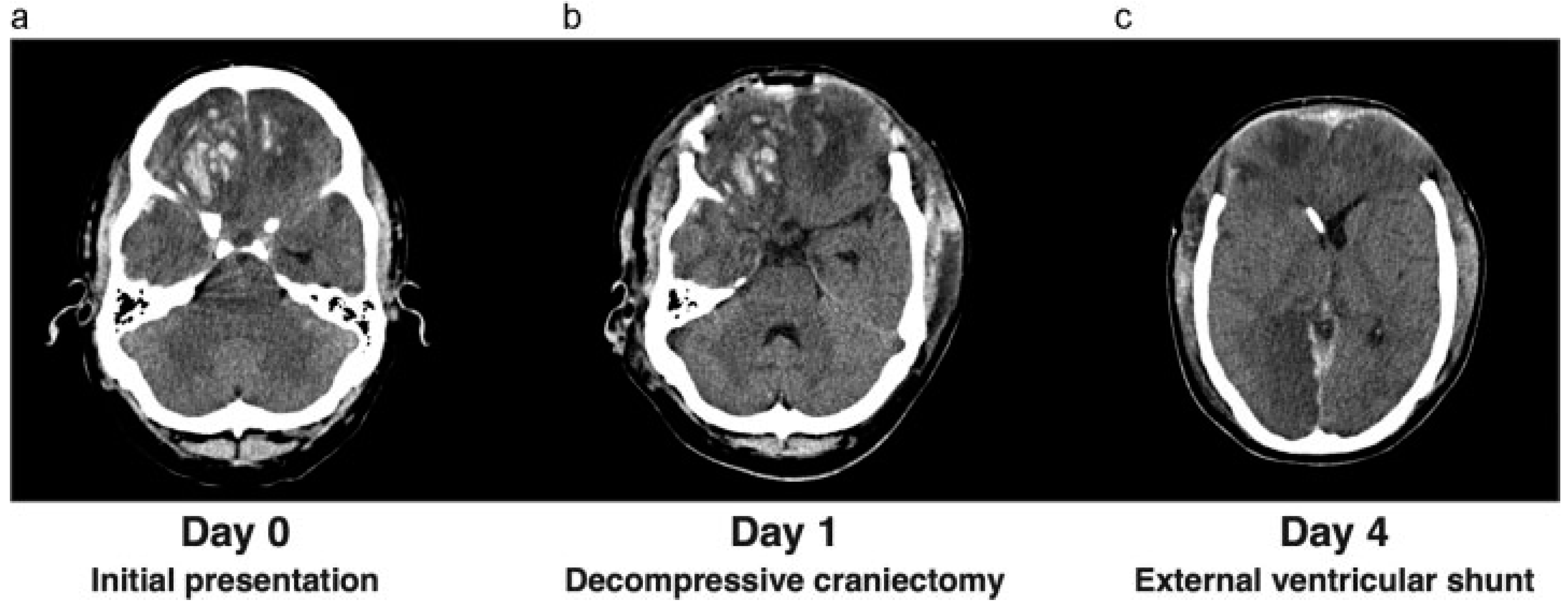
A 27-year-old man was admitted to the neurology department at our hospital after being referred by a rural hospital in the area. He had been in a motor vehicle accident. Upon admittance, his Glasgow coma score (GCS) was E4M6V4. He showed aggressive behavior, and a computed tomography (CT) scan revealed bifrontal cerebral contusions with traumatic subarachnoid hemorrhage, minimal subdural hematoma, and a right-sided fracture of the parietal bone. One day later, his neurologic state had deteriorated to a GCS of E2M5V2. A CT scan was repeated and showed an increase in the cerebral contusions and midline shift (
Figure 1a). Because of clinical deterioration, the patient was admitted to the intensive care unit (ICU). An intraparenchymal ICP meter was inserted for monitoring of the ICP. The ICP was elevated, and intensive treatment with deep sedation and hypertonic fluids failed to adequately restore ICPs to acceptable ranges. Barbiturates were administered as a following step in our ICP treatment protocol; however, the intracranial pressure remained elevated. Because of to the intractable ICP, it was decided to perform a bifrontal decompressive craniectomy (
Figure 1b). The bone flap was placed subcutaneously in the abdomen. A new ICP meter was inserted and revealed a low ICP. After 4 days, the ICP had again risen to unacceptable levels, with the patient showing hydrocephalus on a new CT scan. Consequently, we decided to place an external ventricular shunt (
Figure 1c). This resulted in a satisfactory ICP and remained within the acceptable range during the ICP monitoring. The ICU stay was complicated by a development of a deep venous thrombosis in the patients’ right arm extending to the superior vena cava with pulmonary emboli. Therapeutic dosage of low-molecular-weight heparin was given. After a period of low ICP and stopping supportive treatment, the ICP monitoring and sedation were stopped. The patient awoke and had a GCS of E4M6V1. In addition, he showed contusional behavior and a frontal syndrome. He was discharged from the ICU to our neurosurgical ward.
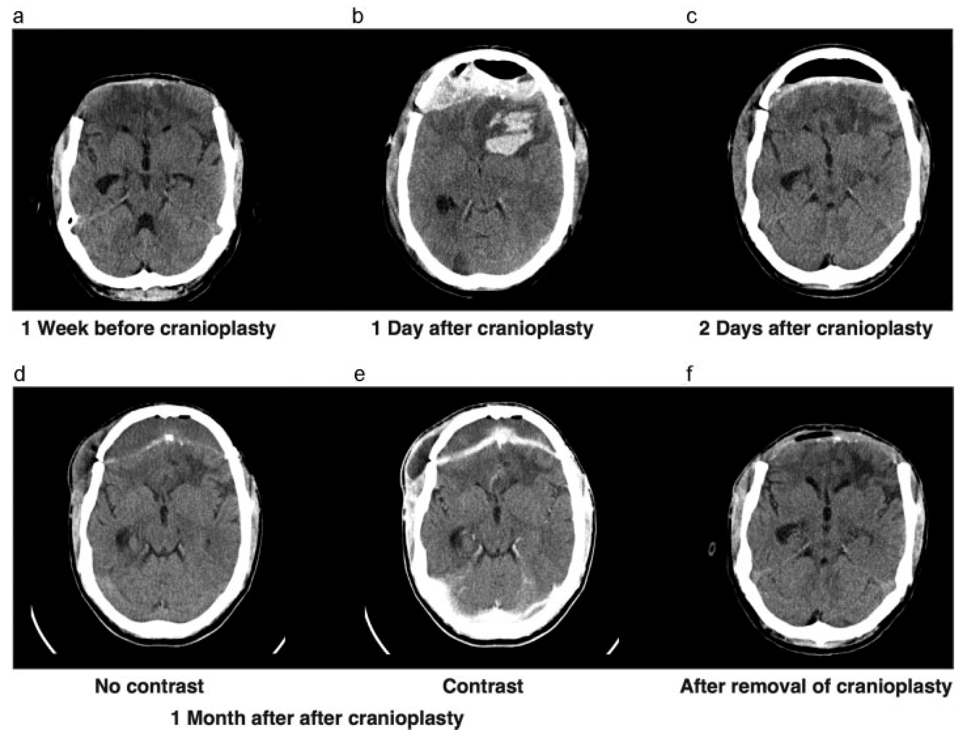
Approximately 2 months later, the cerebral swelling had diminished to the extent that we decided to perform a cranioplasty with the autograft (
Figure 2a). After the cranial reconstruction, the anticoagulant, which was temporarily stopped before surgery, was readministered. Unfortunately, after surgery the patient showed neurologic deterioration based on an epidural hematoma that had to be evacuated immediately and the bone graft was left in place (
Figure 2b,c). After surgery, the patient showed good recovery and went to a cognitive rehabilitation center. However, because of his altered cognitive behavior, we had concerns regarding bone graft infection and wound closure.
One month later, the patient returned with swelling around his right eye, close to the scar. A CT scan showing subcutaneous and epidural collections, in addition to elevated infection parameters in laboratory findings, suggested an infected bone flap (
Figure 2d,e). The bone flap was removed and discarded (
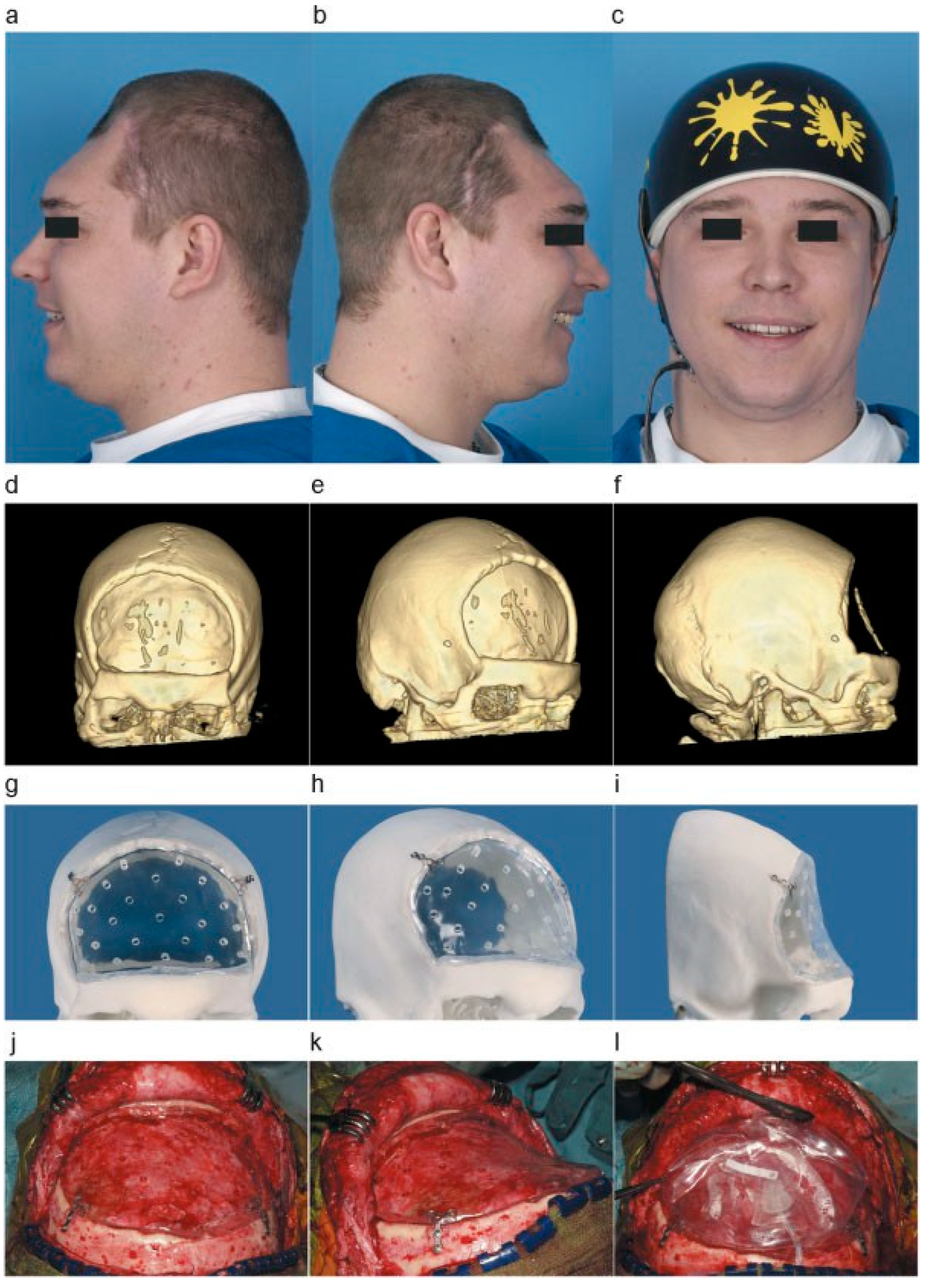
Figure 2f) and intravenous antibiotics were administered. A 3D CT scan was performed to evaluate the bone defect for a future allograft (
Figure 3c–e). In the meantime, a custom-made helmet was worn to protect the brain.
Surgical Technique
After 9 months, the scalp wound was nicely healed from previous surgery and infection. The second cranioplasty could be planned. However, there was extensive scalp atrophy overlying the cranial defect (
Figure 3a,b) and tissue expansion was needed prior to the cranioplasty placement.
By use of the 3D CT scan a custom-made polymethylmethacrylate (PMMA) cranioplasty was manufactured to follow the exact curvature of the skull defect (
Figure 3f–h). The PMMA cranioplasty, functioning as a supporting framework, was placed to fit the skull defect, fixed to the bone with osteosynthetic screws (
Figure 3i,j). On top of the PMMA plate, a silicone tissue expander was placed (
Figure 3k). The filling valve was situated in the temporal region.
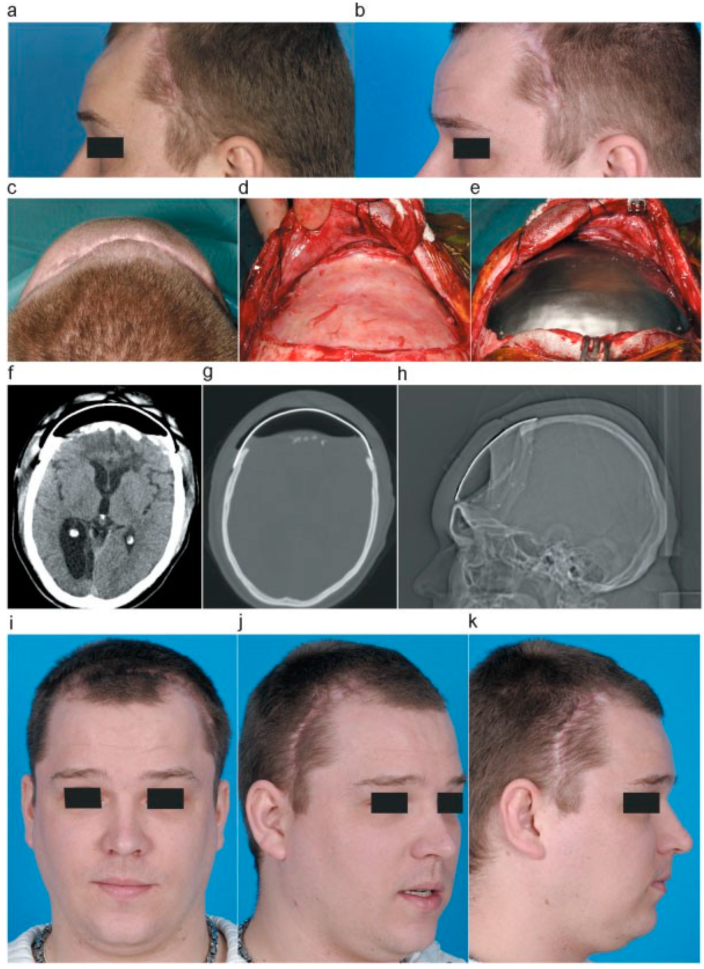
Over a period of 2 months the tissue expander was inflated, on a weekly basis, by sterile introduction of 10-cc saline fluid. During this period the scalp showed good expansion (
Figure 4a,b). In the meantime, a titanium cranioplasty was manufactured to replace the temporary tissue expander and PMMA plate.
Following the scalp expansion, the PMMA cranioplasty and tissue expander were replaced by the titanium allograft. The tissue expander and PMMA plate were removed. A fibrous dural substitution had formed over time (
Figure 4c,d). The bone edges were cleared of tissue. In addition, the titanium cranioplasty was positioned and fixed by osteosynthetic screws (
Figure 4h).
Figure 1.
(a) CT scan before admittance to the ICU, showing bifrontal contusions and swelling. (b) CT scan after decompressive craniectomy. (c) CT scan after placement of external ventricular shunt in the right lateral ventricle.
Figure 1.
(a) CT scan before admittance to the ICU, showing bifrontal contusions and swelling. (b) CT scan after decompressive craniectomy. (c) CT scan after placement of external ventricular shunt in the right lateral ventricle.
Figure 2.
(a) CT scan showing leveling of the brain with bone edges, prior to returning the autograft. (b) CT scan showing epidural and intraparenchymal hematoma 1 day after cranioplasty. (c) CT scan after evacuation of epidural hematoma. (d,e) CT scan before and after contrast showing swelling of right-sided subcutaneous tissue, with contrast enhancement of the dura. (f) CT scan after removal of infected bone graft.
The patient recovered well from surgery (
Figure 4f–h) with good aesthetic result and has shown cognitive behavioral progress during rehabilitation over the next year. Nevertheless, severe cognitive, mainly frontal, symptoms remain as a result of the primary traumatic brain injury.
Discussion
Large skull defects following decompressive surgery can lead to multiple problems if left unattended [
4]. Cranioplasty can minimize these problems. Typically, autologous cranioplasty is performed. Unfortunately, complications such as bone flap infection or bone erosion can occur, resulting in removal or unusability of the bone graft. Without the autograft at hand, other materials can be used to perform secondary cranioplasty. Before reconstructive surgery can be performed, a healing period has to be taken into account, which can amount up to a year [
5,
6]. During this time, atrophy of the scalp tissue over the cranial defect can occur, which can result in insufficient skin coverage during surgery, and thereby risking loss of the implant. It is common to use local skin flaps, free flaps, and skin grafts for scalp reconstruction. This is usually done in oncology patients, burn victims, or after trauma. Cosmetically, these methods do not always give good results. Furthermore, several reports mention additional problems, using these methods for scalp reconstructions such as vascular problems, multiple operations, and lengthy treatment periods [
7,
10,
11].
Tissue expanders can be used to place underneath the scalp tissue to enable adequate scalp closure at the time of definite graft placement. Normally, they are placed overlying an intact skull area, bordering the skull defect. However, several reports show that bone erosion can occur, leading to unnecessary damage [
7,
8,
12].
In our specific case we needed to wait 9 months for the skin to recover after infection and multiple surgery and unfortunately sever atrophy occurred during this period. We encountered an added hindrance in placing a tissue expander in the conventional manner. Because of the severe frontal cognitive behavior of our patient, it was absolutely imperative for him to wear his custom made helmet to protect his brain. Consequently, it was impossible to expand the scalp tissue adjacent to the skull defect, as the helmet would fail to fit adequately. We had to find an approach to simultaneously protect the brain so that the protective helmet was not necessary anymore. By temporarily placing a concave PMMA plate over the existing skull defect, the underlying brain was protected when the tissue expander was inflated. We choose to use the PMMA as it is a relatively cheap material, but robust enough to withhold indentation that may occur during pressure generated from the inflated expander. After placing the PMMA plate, the most logical following step was to place the tissue expander on top of it, because the skin was already mobilized. In addition, because the craniectomy was performed on a non–hear-bearing scalp region, performing scalp expansion on hair-bearing tissue would result in a poor cosmetic outcome.
Figure 3.
(a,b) Left- and right-sided photographs of the patient without bone graft, showing skin atrophy. (c) Photo of patient with custom-made helmet. (d–f) Three-dimensional reconstruction of CT scan showing a large bifrontal skull defect. (g–i) A 3D printed reconstruction of the skull, with the PMMA graft placed in the cranial defect. (j–l) Placement of PMMA plate after mobilizing the pericranium and clearing the osseous edges and fixated by osteosynthetic screws. Placement of the silicon tissue expander over the PMMA graft.
We have used a traditional silicon tissue expander with a filling dome. Several reports of complications have been found using this method; infection, either due to repeated percutaneous saline introduction postoperatively or extreme traction causing wound dehiscence; high-pressure peaks after saline introduction causing hypoxia in tissue leading to skin damage; malfunctioning of filling valve; rupture/leakage of the expander; and skull erosion [
7,
8,
9,
10,
11,
12,
13]. Fortunately, we did not encounter such problems in this case. It is known that expertise in handling traditional tissue expander reduces complications significantly [
14].
Figure 4.
(a,b) Left-sided photographs of patient showing gradual skin expansion after inflating the tissue expander. (c) Axial photograph of patients showing result of skin expansion. (d) After removal of PMMA plate and tissue expander, showing the formation of a fibrous dural substitution. (e) Placement of titanium graft. (f–h) Postoperative CT scan and scanogram, showing positioning of titanium graft. (i–k) Aesthetic result after placement of titanium graft.
A new expansion method has been developed using a self-inflating expander, consisting of hydrogel [
15,
16]. This osmotic tissue enhancer expands by absorbing moisture from the tissue surrounding it over a self-limiting period. In using this method, there is no need for postoperative fillings, resulting in infection reduction. Furthermore, rapid tissue expansion can be achieved, subsequently shorting the treatment period.
However, several complications have also been reported. Skin necrosis and wound dehiscence due to large expander volume, which cannot be reduced without removing the device first. Most importantly, there seems to be no control over the rate and time of the expansion [
17,
18,
19]. In adding a silicone shell around the hydrogel, expanding rate has become slower; however, success rates seem to vary [
13,
20,
21]. In using the traditional tissue expander, we can control the rate and time of inflation, obtaining a good balance between wound traction and skin enhancement resulting in a gradual scalp expansion.
After completing the tissue expansion, we used a titanium cranioplasty as the final element in this reconstruction. Titanium cranioplasty shows low complication rates postoperatively, including low infection rates, and the material has a high mechanical strength that provides great protection for underlying brain [
6,
22].