In-House Virtual Surgery Planning and 3D Printing for Head and Neck Surgery with Free Software: Our Workflow
 ,
, 
Abstract
:Introduction
Workflow (Segmentation, Modeling, Printing, Post-Processing, Validation, and Sterilization)
Segmentation
- Open the 3D Slicer software.
- Drag the folder with the DICOM format images to the program or load it from the “File” section or from the upper toolbar by clicking on “Data”. It is important that no special characters or accents are included in the source folder, as this may cause errors in the loading of the DICOM images.
- Load the patient’s DICOMs that are the subject of the planning in the “DICOM” module.
- Orient the multiplanar reconstructions in the “Transforms” module.
- Select the anatomical structures to be highlighted in the “Volumes” module.
- Generate a preview of the three-dimensional mesh in “Volume Rendering”.
- Adjust the voxels size to be isotropic and define the anatomical area of interest to be segmented with “Crop Volume”.
- Perform the segmentation of the selected volume with the tools of the “Segment Editor” module. The most used tools of this module are the “Threshold” to quickly segment structures based on their Hounsfield Units (HU), and the “Grow from Seeds” from which the “Paint” tool is used to mark areas of interest in one color and areas of no interest in another, identifying HU subgroups to segment structures such as a mandibular tumor, which is different in HU from the rest of the surrounding tissues. With the “Margin” tool, a mesh can be generated that will correspond to the margins we wish to give to the segmented tumor, which are normally 10 to 15 mm. It is important to check the correct segmentation of the structures in the multiplanar reconstructions, according to the previous diagnosis made in the accredited software of the hospital’s own diagnostic imaging machines.
- Through the “Segmentations” module, export the generated mesh to “Models”.
- Once the mesh has been exported to “Models”, it is possible to save the generated object in .stl format. To do this, we must go to “SAVE”, modify the default format of our object from .vtk (Visualization Toolkit) to .stl, and save it in the desired folder.
Modeling
- Open the Meshmixer program.
- Load the STL(s) by dragging them on the start screen from the source folder or with the “Import” option from the start screen, in the left vertical toolbar or in “File”, in the upper left corner. Sometimes if more than one object is imported at the same time and they should be aligned from their segmentation, they may appear separated from each other, to solve this you must import all objects at the same time from the folder with the “Import” option.
- Align the model from the “Edit” module by selecting the “Align” option with all the selected objects of interest.
- Define the front view in the upper right square “Set Current view as Front”. Performing this step together with step 3 facilitates the incorporation of future elements since it positions our object in the center of the three-dimensional space.
- Analyze possible defects in our STL with the “Inspector” option in the “Analysis” module and refine the model with the “Select” module using its functions available in “Edit” and “Deform”. Perform at the end of this process again “Inspector” to ensure that there are no errors and fill those artificially created with “Flat Fill” or “Smooth Fill” as appropriate.
- To create a biomodel (e.g., an orbit), it would be sufficient to generate a solid object with the “Make Solid” function from the “Edit” module, and visually verify its conformation and perform “Inspector” again. If you have had to mirror the contralateral side, you must perform the “Make Solid” after having used the “Mirror” and “Transform” functions, the latter allows us to move our object in space to orient it in its new arrangement as a contralateral orbit.
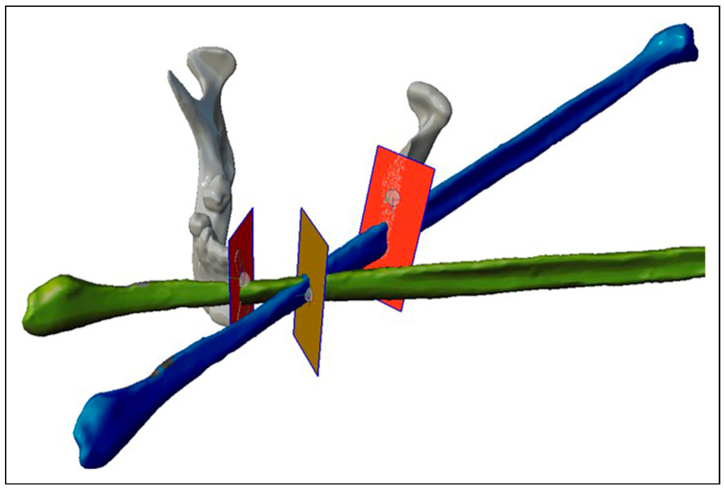
- To design the surgical guides, we will need the “Select” and “Edit” modules. For example, in the case of a mandibular tumor with fibula free flap reconstruction, we will transfer two planes, one on each side of the tumor, for the resection in the location previously decided in the diagnostic phase with the accredited software. These planes will define the angulation of the resection to make it match with the angulation of the fibula flap cut. Therefore, once the planes have been placed on the solid mandible with the “Transform” function, we will use the “Create Pivot” function, both in the “Edit” module and we will place a pivot in the center of the plane by selecting “Snap to Group Center”. We will place the solid fibula with the “Transform” function in the desired position, duplicating the fibula with “Duplicate” according to the fragments we need, and we will include new planes in the intersections between the fragments (Figure 1).
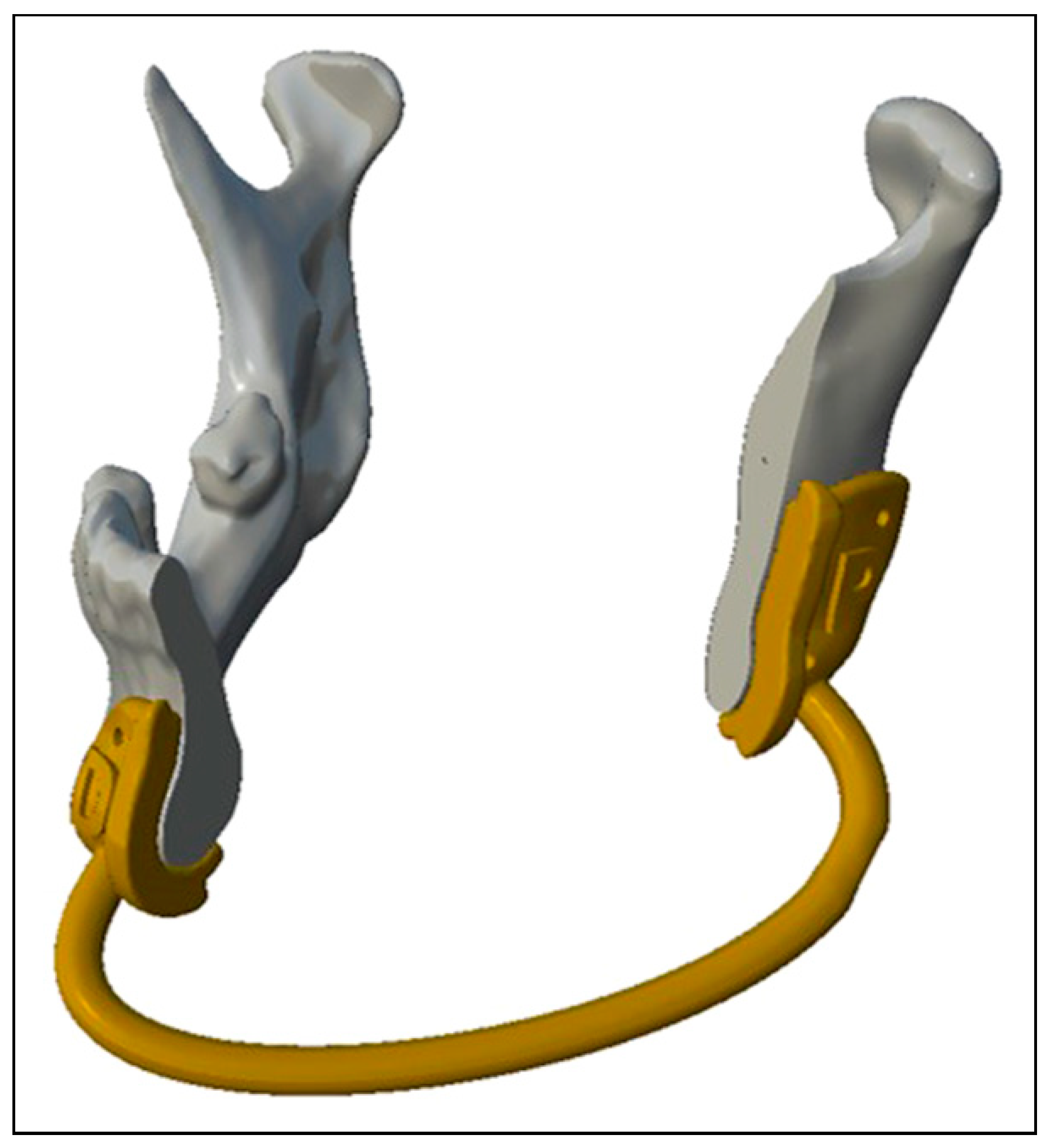
- For the mandibular resection guide, we will use the “Select” module and paint the area of interest, it is recommended to have support of some of the components of the guide on unequivocal anatomical landmarks such as the mandibular angle. Next, we select the edges and perform “Smooth Boundary” to soften them, select everything again and perform “Offset” of 0.5 mm to have a certain margin of error in the adaptation of the guide. We make “Flip Normals” and a new “Offset” but this time of—3 mm so that the guide has 3 mm thickness, the number is negative because when we make “Flip Normals” previously the face is oriented in the opposite direction and in this way we have it oriented back to us. After performing again “Smooth Boundary” on the edges and having both edges selected, we perform the “Join” function to close the mesh. With the mesh closed we will make an “Extrude” of 3 mm selecting the edges around the cutting plane to improve the contact surface with the saw. From the “Meshmix” module in the “Letters” section, we drag on the guide, a P or a D, for example, to mark the fragments of the guide as proximal or distal and orient it more easily. Then, we will do “Make Solid” and we will only have to do “Plane Cut” oriented on the Pivots of the cutting planes to remove the part of the guide that we do not want, creating a flange type resection guide. To make the holes to fix the guide we will use cylinders that we will drag to the guide from the “Meshmix” module that we find in the “Primitives” section. The diameter of the cylinders must match the diameter of the screws used to fix the guide. To perform this substraction, we will need a Boolean operation and it does not usually give error if it is done when the cylinders and the guide are converted into solid. After placing the prisms through the guide with “Transform”, we select first the guide and then the cylinders in the “Edit” module to perform the “Boolean Difference” function and subtract the cylinders from the guides. In addition, we recommend adding with the “Add Tube” function from the “Edit” module a tube of 3 mm radius by selecting “Spline (Outside)”, with the combination “Boolean” and with an appropriate “Target Len”, which allows to better place the most distal fragment of the guide or those fragments of the same with worse anatomical reference, it is convenient to add it before making the solid object so that when “Make Solid” is performed, the generated tube is included (Figure 2).
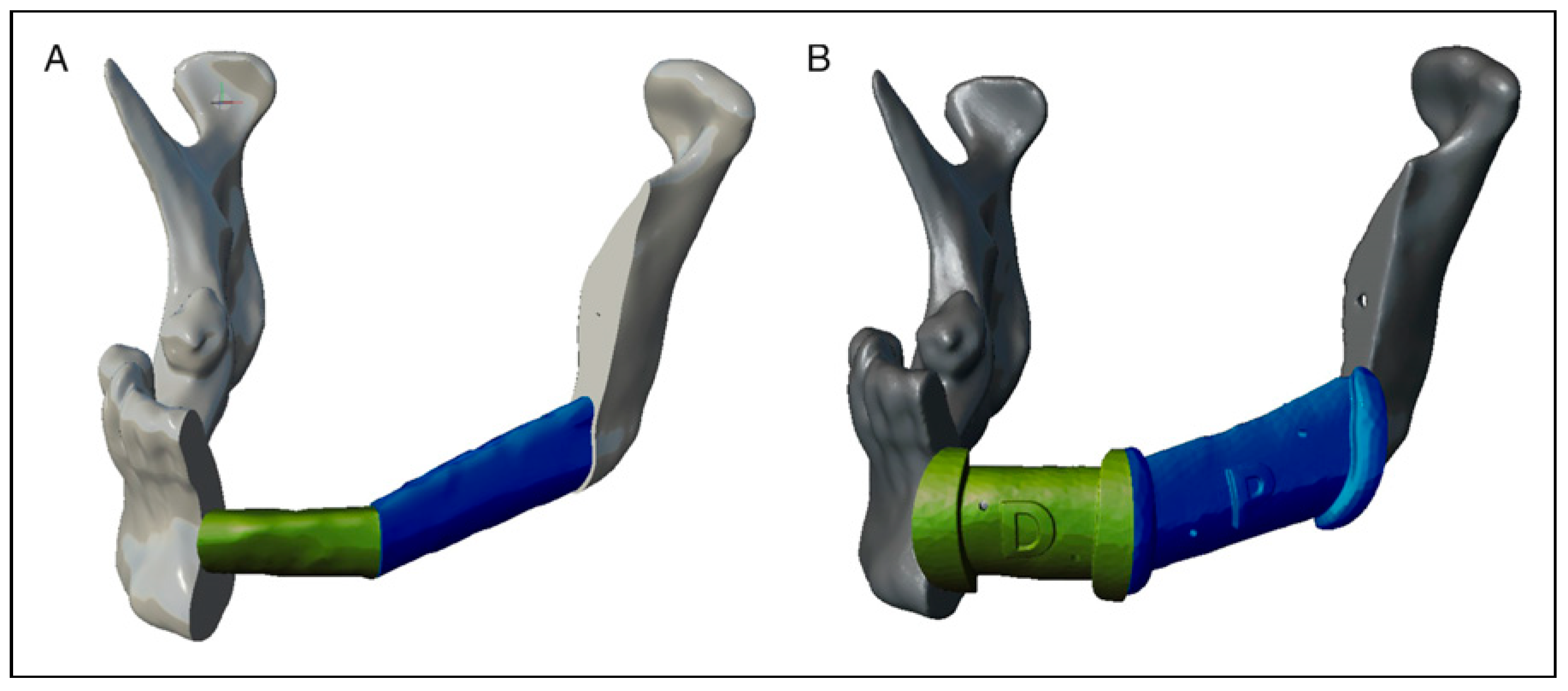
- For the fibula cutting guide, we will have to perform the same steps, but each guide will be designed on the fibula placed in its final position on the mandible, obtaining as many guides as fragments of fibula we design, obtaining guides separated from each other, being the surgeon who intraoperatively decides the distance between the fragments if there is more than one. We will use “Plane Cut” oriented on the Pivots in the same way as in the case of the resection guide. Another option (for both guides) is to design boxes with grooves to set the direction of the saw cut (slot type resection guide). The fibula guide can be designed (when it has more than one fragment) as a set moving the cutting planes to a fibula that will be used as working fibula out of its position in the mandible, although we agree with what has been published that it only increases the design time not adding more precision; therefore, we prefer the flange type resection guide directly over the final position of the fibula fragments [7] (Figure 3).
- For the biomodel of the resection on which we can adapt a stock reconstruction plate, we will only have to obtain with “Plane Cut” on the Pivots of the planes of both the mandibular resection and the intersections of the fibula, obtaining on one side the distal and proximal mandibular fragments, as well as the fibula fragment or fragments. These fragments, previously being already solid, we elect them at the same time and we join them in the same object from the “Edit” module with the “Combine” function. Then we will make a new “Make Solid” of the set, since normally the result of the operation causes the fragments to merge since there is no real distance separating them. For the “Make Solid” functions, we recommend selecting “Accurate” in the “Solid Type” option and usually, a “Solid Accuracy” and “Mesh Density” higher than 200 is not necessary to obtain a good definition and density.
- If a positioning guide of the fibula fragments with respect to the remnant mandible is required, a “mandible guiding tray” can be designed according to the design described by Arce et al. [25]
- It should be analyzed one last time with “Inspector” to repair possible defects of our guide or biomodel prior to export.
- Export the generated surgical guide in Binary STL format from the “Export” module.
Validation
- We will import the mesh to the workspace. The first thing that the application will ask us is if we want to unify duplicated vertices, to which we select yes.
- Select the menu “Filters”, the module “quality measure and computations” and the option “compute topological measures”: at this point, we can determine the number of vertices, edges, and faces, if the mesh has unreferenced vertices, if it has 0 holes, its genus, the number of connected components, and the most important thing is the type of mesh: twomanifold or non-manifold. For example, the program indicates in a pop-up window the information about a two-manifold mesh: V: 216 E: 642 F: 428, Unreferenced Vertices 0, Boundary Edges 0, Mesh is composed by 2 connected components, Mesh has 0 holes, Genus is 1, Mesh is two-manifold.
- Our objective is that the mesh to be studied is twomanifold, so all the points of the example must be fulfilled, since the mesh is closed, has no holes, no duplicity of vertices, and no referencing. In this case, the mesh will be ready for printing and will have no errors in the lamination program.
- In the case that the mesh is non-manifold, we see, for example, how the program would indicate in a pop-up window the information: V: 7933 E: 23796 F: 15852, Unreferenced Vertices 0, Boundary Edges 44, Mesh is composed by 4 connected component(s), Mesh has 4 non-two-manifold edges and 12 faces are incident on these edges, Mesh has 5 non-two-manifold vertexes and 26 faces are incident on these vertices, Genus is undefined (non-two-manifold mesh), Mesh has an undefined number of holes (non-two-manifold mesh). The process is complicated by the fact that it will be necessary to analyze on the mesh all the open edges, duplicated faces, and edges used by more than two triangles, until a good printable two-manifold mesh is obtained.
Printing and Post-Processing
Sterilization
Discussion
Conclusions
Funding
Institutional Review Board Statement
Conflicts of Interest
Appendix
| CAD/CAM | Computer-aided design/computer-aided manufacturing |
| CT | Computerized Tomography |
| FDM Printer | Fused Deposition Modeling |
| IH | In-House |
| IH3D | In-House 3D Department |
| MCID | Minimal Clinically Important Difference |
| MRI | Magnetic Resonance Imaging |
| PET | Positron Emission Tomography |
| PSI | Patient-specific implants |
| SLA | Sterelitography Printer |
| STL or .stl | Stereolithography |
| USP | United States Pharmacopeia |
| VTK | Visualization Toolkit |
References
- Powcharoen, W.; Yang, W.F.; Yan Li, K.; Zhu, W.; Su, Y.X. Computer-Assisted versus conventional freehand mandibular reconstruction with fibula free flap: A systematic review and meta-analysis. Plast. Reconstr. Surg. 2019, 144, 1417–1428. [Google Scholar] [CrossRef] [PubMed]
- Lee, Z.H.; Alfonso, A.R.; Ramly, E.P.; et al. The latest evolution in virtual surgical planning: Customized reconstruction plates in free fibula flap mandibular reconstruction. Plast. Reconstr. Surg. 2020, 146, 872–879. [Google Scholar] [CrossRef]
- Yang, W.F.; Choi, W.S.; Wong, M.C.; et al. Three-dimensionally printed patient-specific surgical plates increase accuracy of oncologic head and neck reconstruction versus conventional surgical plates: A comparative study. Ann. Surg. Oncol. 2021, 28, 363–375. [Google Scholar] [CrossRef]
- Padilla, P.L.; Mericli, A.F.; Largo, R.D.; Garvey, P.B. Computeraided design and manufacturing versus conventional surgical planning for head and neck reconstruction: A systematic review and meta-analysis. Plast. Reconstr. Surg. 2021, 148, 183–192. [Google Scholar] [CrossRef]
- Ruxu, D.; Su, Y.S.; Yan, Y.; et al. A systematic approach for making 3D-printed patient-specific implants for craniomaxillofacial reconstruction. Engineering 2020, 6, 1291–1301. [Google Scholar] [CrossRef]
- Yang, W.F.; Zhang, C.Y.; Choi, W.S.; et al. A novel ‘surgeondominated’ approach to the design of 3D-printed patientspecific surgical plates in mandibular reconstruction: A proofof-concept study. Int. J. Oral. Maxillofac. Surg. 2020, 49, 13–21. [Google Scholar] [CrossRef]
- Abo Sharkh, H.; Makhoul, N. In-house surgeon-led virtual surgical planning for maxillofacial reconstruction. J. Oral. Maxillofac. Surg. 2020, 78, 651–660. [Google Scholar] [CrossRef] [PubMed]
- Bosc, R.; Hersant, B.; Carloni, R.; et al. Mandibular reconstruction after cancer: An in-house approach to manufacturing cutting guides. Int. J. Oral. Maxillofac. Surg. 2017, 46, 24–31. [Google Scholar] [CrossRef] [PubMed]
- Damecourt, A.; Nieto, N.; Galmiche, S.; Garrel, R.; de Boutray, M. In-house 3D treatment planning for mandibular reconstruction by free fibula flap in cancer: Our technique. Eur. Ann. Otorhinolaryngol. Head. Neck Dis. 2020, 137, 501–505. [Google Scholar] [CrossRef]
- Dell’Aversana Orabona, G.; Abbate, V.; Maglitto, F.; et al. Lowcost, self-made CAD/CAM-guiding system for mandibular reconstruction. Surg. Oncol. 2018, 27, 200–207. [Google Scholar] [CrossRef]
- Luu, K.; Pakdel, A.; Wang, E.; Prisman, E. In house virtual surgery and 3D complex head and neck reconstruction. J. Otolaryngol. Head. Neck Surg. 2018, 47, 75. [Google Scholar] [CrossRef] [PubMed]
- Lor, L.S.; Massary, D.A.; Chung, S.A.; Brown, P.J.; Runyan, C.M. Cost analysis for in-house versus industry-printed skull models for acute midfacial fractures. Plast. Reconstr. Surg. Glob. Open. 2020, 8, e2831. [Google Scholar] [CrossRef] [PubMed]
- Ballard, D.H.; Mills, P.; Duszak RJr Weisman, J.A.; Rybicki, F.J.; Woodard, P.K. Medical 3D printing cost savings in orthopedic and maxillofacial surgery: Cost analysis of operating room time saved with 3D printed anatomic models and surgical guides. Acad. Radiol. 2020, 27, 1103–1113. [Google Scholar] [CrossRef]
- Li, S.S.; Copeland-Halperin, L.R.; Kaminsky, A.J.; Li, J.; Lodhi, F.K.; Miraliakbari, R. Computer-aided surgical simulation in head and neck reconstruction: A cost comparison among traditional, inhouse, and commercial options. J. Reconstr. Microsurg. 2018, 34, 341–347. [Google Scholar] [CrossRef] [PubMed]
- ISO 13485:2016; Medical Devices—Quality Management Systems—Requirements for Regulatory Purposes. Springer: Cham, Switzerland, 2022.
- MDCG 2019-11 Guidance on Qualification and Classification of Software in Regulation (EU) 2017/745 MDR and Regulation (EU) 2017/746 IVDR. Available online: https://ec.europa.eu/docsroom/documents/37581 (accessed on 7 February 2023).
- Regulation (EU) 2017/745 of the European Parliament and of the Council of 5 April 2017 on Medical Devices, Amending Directive 2001/83/EC, Regulation (EC) No 178/2002 and Regulation (EC) No 1223/2009 and Repealing Council Directives 90/385/EEC and 93/42/EEC. Available online: https://Eur-Lex.Europa. Eu/Legal-Content/EN/TXT/?Uri=CELEX%3A32017R0745 (accessed on 7 February 2022).
- MDCG 2021-24: Guidance on Classification of Medical Devices. Available online: https://health.ec.europa.eu/system/files/2021-10/mdcg_2021-24_en_0.pdf (accessed on 6 August 2023).
- MDCG 2021-3: Questions and Answers on Custom-Made Devices & Considerations on Adaptable Medical Devices and Patient-Matched Medical Devices. Available online: https://health.ec.europa.eu/system/files/2021-03/mdcg_2021-3_en_0.pdf (accessed on 6 August 2023).
- ISO 10993-1:2018; Biological Evaluation of Medical Devices—Part 1: Evaluation and Testing Within a Risk Management Process. AAMI: Arlington, VA, USA, 2020. Available online: https://www.iso.org/standard/68936.html (accessed on 7 February 2023).
- Directive 2006/42/EC of the European Parliament and of the Council of 17 May 2006 on Machinery, and Amending Directive 95/16/EC. Available online: https://eur-lex.europa.eu/legal-content/EN/TXT/?uri=CELEX:02006L0042-20190726 (accessed on 7 February 2023).
- Fedorov, A.; Beichel, R.; Kalpathy-Cramer, J.; et al. 3D slicer as an image computing platform for the quantitative imaging network. Magn. Reson. Imaging. 2012, 30, 1323–1341. [Google Scholar] [CrossRef]
- Sato, T.; Takagi, T. Validation of the influence of CT slice thickness on the quantitative accuracy and image quality of single photon emission computed tomography. Asia Ocean. J. Nucl. Med. Biol. 2021, 9, 148–157. [Google Scholar] [CrossRef]
- Autodesk Meshmixer. Available online: https://meshmixer.com/download.html (accessed on 8 February 2023).
- Arce, K.; Waris, S.; Alexander, A.E.; Ettinger, K.S. Novel patient-specific 3-dimensional printed fixation tray for mandibular reconstruction with fibular free flaps. J. Oral. Maxillofac. Surg. 2018, 76, 2211–2219. [Google Scholar] [CrossRef]
- Cignoni, P.; Callieri, M.; Corsini, M.; Dellepiane, M.; Ganovelli, F.; Ranzuglia, G. MeshLab: An open-source mesh processing tool. In Computing. 2008, 1, 129–136. [Google Scholar] [CrossRef]
- USP Drug Classification. Available online: https://www.usp.org/health-quality-safety/usp-drug-classification-system#:∼:text=Organization_of_USP_DC_2023&text=A_USP_Category_is_the,a_high_level_formulary_structure.&text=A_USP_Class_is_a,the_ USP_Drug_Classification_system (accessed on 7 February 2023).
- ASTM E2092-09. Standard Test Method for Distortion Temperature In Three-Point Bending by Thermomechanical Analysis. Available online: https://www.astm.org/e2092-09.html. (accessed on 12 March 2023).
- Yang, W.F.; Choi, W.S.; Zhu, W.Y.; et al. Spatial deviations of the temporomandibular joint after oncological mandibular reconstruction. Int. J. Oral. Maxillofac. Surg. 2022, 51, 44–53. [Google Scholar] [CrossRef]
- Tarsitano, A.; Battaglia, S.; Crimi, S.; Ciocca, L.; Scotti, R.; Marchetti, C. Is a computer-assisted design and computer- assisted manufacturing method for mandibular reconstruction economically viable? J. Cranio-Maxillo-Fac. Surg. 2016, 44, 795–799. [Google Scholar] [CrossRef]
- Zweifel, D.F.; Simon, C.; Hoarau, R.; Pasche, P.; Broome, M. Are virtual planning and guided surgery for head and neck reconstruction economically viable? J. Oral. Maxillofac. Surg. 2015, 73, 170–175. [Google Scholar] [CrossRef] [PubMed]
- Pu, J.J.; Choi, W.S.; Yu, P.; Wong, M.C.M.; Lo, A.W.I.; Su, Y.X. Dopredetermined surgical margins compromise oncological safety in computer-assisted head and neck reconstruction? Oral. Oncol. 2020, 111, 104914. [Google Scholar] [CrossRef] [PubMed]
© 2023 by the authors. The Author(s) 2023.
Share and Cite
Gómez, V.J.; Martín-González, A.; Zafra-Vallejo, V.; Zubillaga-Rodríguez, I.; Fernández-García, A.; Sánchez-Aniceto, G. In-House Virtual Surgery Planning and 3D Printing for Head and Neck Surgery with Free Software: Our Workflow. Craniomaxillofac. Trauma Reconstr. 2024, 17, 331-339. https://doi.org/10.1177/19433875231211759
Gómez VJ, Martín-González A, Zafra-Vallejo V, Zubillaga-Rodríguez I, Fernández-García A, Sánchez-Aniceto G. In-House Virtual Surgery Planning and 3D Printing for Head and Neck Surgery with Free Software: Our Workflow. Craniomaxillofacial Trauma & Reconstruction. 2024; 17(4):331-339. https://doi.org/10.1177/19433875231211759
Chicago/Turabian StyleGómez, Vicenç J., Antonio Martín-González, Víctor Zafra-Vallejo, Ignacio Zubillaga-Rodríguez, Antonio Fernández-García, and Gregorio Sánchez-Aniceto. 2024. "In-House Virtual Surgery Planning and 3D Printing for Head and Neck Surgery with Free Software: Our Workflow" Craniomaxillofacial Trauma & Reconstruction 17, no. 4: 331-339. https://doi.org/10.1177/19433875231211759
APA StyleGómez, V. J., Martín-González, A., Zafra-Vallejo, V., Zubillaga-Rodríguez, I., Fernández-García, A., & Sánchez-Aniceto, G. (2024). In-House Virtual Surgery Planning and 3D Printing for Head and Neck Surgery with Free Software: Our Workflow. Craniomaxillofacial Trauma & Reconstruction, 17(4), 331-339. https://doi.org/10.1177/19433875231211759