Next Article in Journal
The Effect of Chitohem Bleeding Inhibitor Powder on Pain and Bleeding After Tonsillectomy by Suturing Method
Previous Article in Journal
Extended Total Temporomandibular Joint Replacement—A Feasible Option for Functional and Aesthetic Reconstruction of Mandibular Defects Involving the Temporomandibular Joint
 
 
Craniomaxillofacial Trauma & Reconstruction is published by MDPI from Volume 18 Issue 1 (2025). Previous articles were published by another publisher in Open Access under a CC-BY (or CC-BY-NC-ND) licence, and they are hosted by MDPI on mdpi.com as a courtesy and upon agreement with Sage.
Article

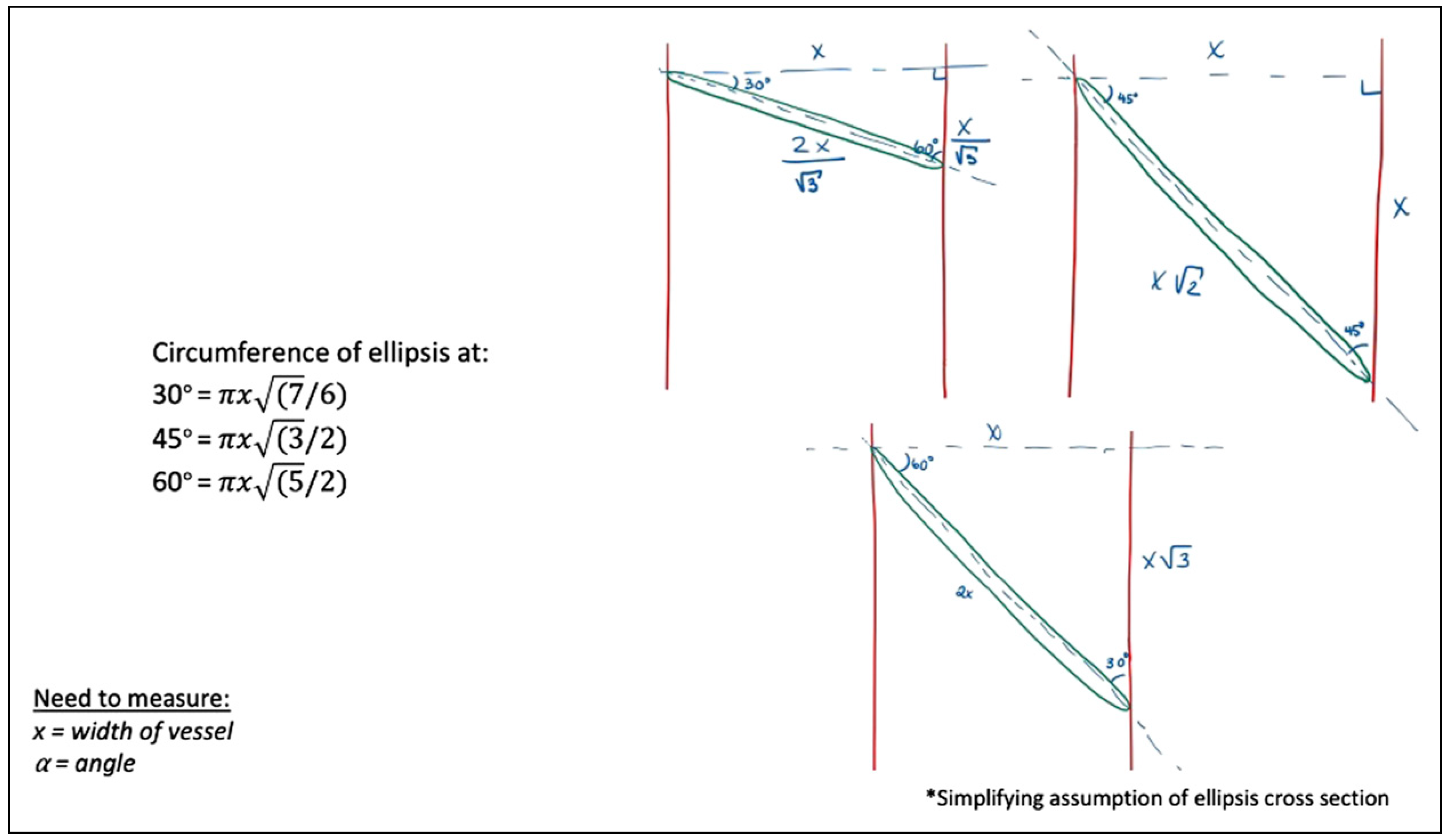
Mathematical Modeling of Vessel Geometry and Circumference in Microvascular Surgery

by
Stacey Nedrud
1,*,
Yoram Fleissig
2,3,
Alba Sanjuan-Sanjuan
1,
Anthony Bunnell
1 and
Rui Fernandes
1
1
Department of Oral & Maxillofacial Surgery, Division of Head and Neck Surgery, University of Florida Health Jacksonville, 653 W. Eighth Street, 2nd Floor, LRC Building, Jacksonville, FL 32209, USA
2
Faculty of Dental Medicine, Hebrew University of Jerusalem, Jerusalem, Israel
3
Department of Oral & Maxillofacial Surgery, Hadassah Medical Center, Jerusalem, Israel
*
Author to whom correspondence should be addressed.
Craniomaxillofac. Trauma Reconstr. 2023, 16(3), 195-204; https://doi.org/10.1177/19433875221097252
Submission received: 1 November 2021 / Revised: 1 December 2021 / Accepted: 1 January 2022 / Published: 15 May 2022

Abstract

:
Introduction: Microvascular anastomosis has traditionally been executed with a perpendicular transection through the vessel at the widest diameter to increase circumference and thus increase blood flow while decreasing resistance. In Chen’s 2015 article, it was suggested that an “open Y” would improve vessel size match, and Wei and Mardini discuss angled transections of the vessels. This project aims to explore the geometric configurations feasible at the anastomotic transection and mathematically model the resulting hypothetical increases in circumference. Materials and Methods: The mathematical models were theoretically developed by our team. The formulas model increases in circumference of the transection at different distances in relation to the bifurcation of a blood vessel, as well as changes in circumference at different transection angulations. An in vitro exploration as to the anastomotic feasibility of each geometric cut was completed on ten poultry tissue specimens. Results: The mathematical models demonstrated the change in vessel circumference, with multiple geometric designs calculated, best shown through diagrams. For example, if the vessel width is 1 mm, the distance from the increasing vessel diameter to the final bifurcation is 1 mm, and the bifurcation angle is 45°, the circumference of the transected vessel increases by 82.8%. Models of transections at different angulations, for instance 30°, 45°, and 60°, yield an increase in elliptical circumference of 8.0%, 22.5%, and 58.1%, respectively. Additional derivations calculate the elliptical circumference at any angle in a single vessel, and at any angle in a bifurcating vessel. Conclusion: The theoretical and clinical aim of this project is to increase awareness of the anastomotic creativity and mathematically demonstrate the optimal anastomotic geometry, which has not been objectively explored to our knowledge. An in vivo study would further support clinical improvements, with the aim to map postoperative fluid dynamics through the geometric anastomoses.

Introduction

Microvascular anastomosis for free flap reconstruction has traditionally been executed with a perpendicular transection through the blood vessel at the widest diameter to increase circumference and thus increase blood flow while decreasing resistance. Improved flow avoids the known complications including arterial and venous insufficiency or thrombosis. While comorbidities and anatomy contribute to failure rates, surgical technique, and vessel selection is paramount. Especially challenging is vessel size discrepancy. Multiple techniques are established in the literature, but there is no consensus as to superiority. Akan et al. described utilizing the “open Y” technique to address this common situation with
success, and then further analyzed a combination “open Y” end-to-side model [1,2,3]. Similarly, Chen et al. [4] evaluated the “open Y” to improve vessel size match and vessel geometry utilizing the superior thyroid artery with similar success rates to traditional microvascular techniques. Wei and Mardini’s reconstructive surgery text also suggests solutions for vessel mismatch, including oblique cuts not exceeding an angle of 30° to increase vessel circumference [5].
This study aims to explore the geometric configurations feasible at the vessel transection site, and mathematically model the resulting changes in circumference. The hypothetical increase in vessel diameter based on location and change in angulation of transection has been evaluated clinically but has not yet been objectively modeled.

Materials and Methods

The mathematical models were theoretically developed by our team. The formulas model increases in circumference of the transection at different distances in relation to the bifurcation of a blood vessel, as well as changes in circumference at different transection angulations. To calculate circumference based on either the assumption of a circle or an ellipsis both introduced a margin of error to the formulas derived, but this margin was accepted due to the mathematical models representing elastic tissue, instead of a fixed-size material, which inherently adds a factor of estimation.
An in vitro exploration as to the anastomotic feasibility of each geometric cut was completed on 10 poultry tissue specimens as examples, and calculations were assessed based on these clinical models. However, no flow modeling or otherwise clinically applicable testing was performed on these specimens, as this study was focusing on the theoretical aspect of the geometry.
No institutional review board was required for this theoretical study according to our institution standards.

Results

The in vitro poultry models of the hypothetical changes in vessel circumference are best demonstrated in the clinical figures. Figure 1 depicts the microvascular lab set up on the poultry specimens, with Figure 2 demonstrating the ideal size-matched vessel for a successful anastomosis. The common presentation of vessel bifurcation in Figure 3 can be advantageous if harnessed by either Akan's "open Y" method demonstrated in Figure 4 and Figure 5, or by simply transecting the vessel just below the bifurcation, but distal to the takeoff area where the vessel begins to diverge into the two branches, as in Figure 6. Utilizing the "open Y" technique, one must also account for the necessary trimming to ensure the vessel circumference is even without irregularities or intimal flaps, which can decrease the circumference achieved. The plasticity and increase in size of circumference is visible in both the artery and vein, as in Figure 7 and Figure 8, and cannot be represented mathematically. In vivo, this technique has been used at our institution with excellent outcomes, as seen through the microscope in Figure 9, and through SPY angiography in Figure 10.
The mathematical models demonstrated the change in vessel circumference, with multiple geometric designs calculated, best shown through diagrams. Figure 11 begins by assuming a circular cross-section after transection. Assuming this cylindrical blood vessel with a diameter, w, in millimeters (mm). If the takeoff point where the vessel begins to diverge is 0 mm, and we examine the distance from that point, a distance of, x, millimeter traveling distally to the point of bifurcation, we can define our new diameter at, d, mm, assuming a divergence angle at the bifurcation of, α, degrees, we utilized simple geometric principles to calculate the new circumference at, x, millimeter from the original vessel diameter of, w, millimeter. For example, if the vessel width is 1 mm (w = 1 mm), the distance from the increasing vessel diameter to the final bifurcation is 1 mm (x = 1 mm), and the bifurcation angle is 45° (α = 45°), the circumference of the transected vessel increases by 82.8%. If the same example has a bifurcation angulation of 30° (α = 30°), the increase is 54.1%.
Figure 12 was developed to broaden the model to any angulation of cross-section at each branch of a bifurcation separately, which is increasingly theoretical, assuming an ellipsis due to the varying cross-sections possible. This model separates each branch of the bifurcation, to account for the possibilities of differing angulations of cross-sections, θ and δ, utilizing the "open Y" technique. Again, this does not account for any revisions of the edges at the cross-section to facilitate the configuration for anastomosis.
More clinically applicable, Figure 13 explores the widely-accepted oblique cross-section. Simplifying to angles of 30°, 45°, and 60°, these models calculate the elliptical circumference in relation to the traditional perpendicular cross-section, of x millimeter. Comparing, for instance, oblique transections at angles of 30°, 45°, and 60°, yields an increase in elliptical circumference of 8.0%, 22.5%, and 58.1%, respectively.
Figure 14 again broadens the previous model to any angulation, θ, to calculate the new circumference, based on the original perpendicular cross-section diameter of, a, mm, estimating based off an elliptical cross-section.

Discussion

Vessel selection, size discrepancy, and microvascular technique can affect the patency, blood flow, and predisposition to thrombus in a microvascular free flap [4,6,7,8,9,10]. This has been addressed through various techniques such as dilation, unequal bite suturing, oblique cuts, fish-mouth incisions, sleeve anastomoses, end-to-side anastomoses, supermicrosurgery, among others [1,2,5,7,11,12,13,14,15,16,17,18,19,20]. Akan et al. beautifully described the “open Y” technique and subjectively illustrated the benefits, which has a particular advantage besides increasing lumen size, but also naturally everting the lumen edges to decrease turbulence in the vessel flow [1,2,7]. Chen et al. [4] saw no significant difference in the success or complication rate of the “open Y” technique with the superior thyroid artery in cases of vessel mismatch, compared to traditional techniques with less mismatch. Scaglioni et al. also heralded the successes of an “open Y” technique to employ end-to-end anastomoses with increased size, eversion of edges, and reduced turbulence and risk of thrombus formation. Their study, while small in sample size, showed a decrease in complication rate compared to conventional end-to-end anastomoses (10% vs 31%) [8]. End-to-side anastomoses are also well described, initially by Godina [21,22,23], and Akan furthered the technique to evaluate the “open Y” end-toside anastomosis compared to end-to-end anastomosis, with statistically significant improvement in flow at 14 days in a rat model [3].
While the notion of angled and bifurcated microvascular cross-sections to improve vessel mismatch is not novel, there have thus far been no objective models of the benefits gained from the technique. These mathematical models are solely theoretical and would be impractical to measure and calculate intraoperatively based on the vasculature presented in each unique situation. However, the purpose of this exploration is to prove the theoretical hypotheses previously described, which can then be directly and objectively applied intraoperatively. These techniques seem to be underestimated in their mathematical ability to improve vessel mismatch with minimal additional surgical effort or overly complex surgical technique, even for the novice surgeon. Moreover, our model of the “open Y” technique highlights 2 variables that can help the microvascular surgeon optimize vessel size: the angle of bifurcation (α) and the distance to bifurcation point (x). Simplifying the equations, the larger the angle, the more significant the increase in vessel size; the larger the distance to bifurcation, the more significant the increase in vessel size. These variables can be quickly assessed intraoperatively, with no need for precise measurements.
More sophisticated evaluations of fluid dynamics of the flow through the differing geometries could help to further augment the intraoperative decision protocol and correlate postoperative outcomes [24,25,26].

Conclusion

The theoretical and clinical aim of this project is to increase awareness of the anastomotic creativity and mathematically demonstrate the optimal anastomotic geometry, which has not been objectively explored to our knowledge. An in vivo study would further support clinical improvements, with the aim to map postoperative fluid dynamics through the geometric anastomoses.

Author’s Note

There have been no prior publications of this work. This idea was presented at the 2021 EACMFS Virtual Congress as an oral presentation.

Author Contributions

All authors contributed equally to all CRediT roles.

Funding

The author(s) received no financial support for the research, authorship, and/or publication of this article.

Consent

Consent has been obtained for patient images used.

Conflicts of Interest

The author(s) declared no potential conflicts of interest with respect to the research, authorship, and/or publication of this article.

References

  1. Akan, M.; Cakir, B.; Aköz, T. “Open Y” technique in vessel diameter discrepancy. Microsurgery 2006, 26, 506–514. [Google Scholar] [CrossRef] [PubMed]
  2. Akan, M.; Cakir, B.; Aköz, T. Increasing vessel diameter with the open Y technique for diameter discrepancy. J. Reconstr. Microsurg. 2004, 20, 651–657. [Google Scholar] [CrossRef] [PubMed]
  3. Akan, M.; Cakir, B.; Gideroglu, K.; Aköz, T.; Kavurmacioglu, L. End-to-side anastomosis with “Open-Y” technique on small vessels to increase patency and facilitate anastomosis. J. Craniofac Surg. 2009, 20, 2226–2229. [Google Scholar] [CrossRef] [PubMed]
  4. Chen, Y.-C.; Scaglioni, M.F.; Huang, E.-Y.; Kuo, Y.-R. Utility of “open-Y” anastomosis technique in the use of superior thyroid artery as recipient vessel for head and neck reconstruction with free flap. Microsurgery 2016, 36, 391–396. [Google Scholar] [CrossRef]
  5. Sabapathy, S.R. Vessels. In Flaps and Reconstructive Surgery, 2nd ed.; Wei, F.-C., Mardini, S., Eds.; Elsevier: London, NY, 2017; pp. 310–322. [Google Scholar]
  6. Chia, H.-L.; Wong, C.-H.; Tan, B.-K.; Tan, K.-C.; Ong, Y.-S. An algorithm for recipient vessel selection in microsurgical head and neck reconstruction. J. Reconstr. Microsurg. 2011, 27, 047–056. [Google Scholar] [CrossRef]
  7. López-Monjardin, H.; de la Peña-Salcedo, J.A. Techniques for management of size discrepancies in microvascular anastomosis. Microsurgery 2000, 20, 162–166. [Google Scholar] [CrossRef] [PubMed]
  8. Scaglioni, M.F.; Meroni, M.; Fritsche, E. Application of the “Open-Y” technique in recipient perforator vessels: A comparison study between“ Open-Y” and conventional end-to-end anastomosis in terms of postoperative complications. Microsurgery 2021, 41, 527–532. [Google Scholar] [CrossRef]
  9. Wain, R.A.J.; Whitty, J.P.M.; Dalal, M.D.; Holmes, M.C.; Ahmed, W. Blood flow through sutured and coupled microvascular anastomoses: A comparative computational study. J. Plast. Reconstr. Aesthetic Surg. 2014, 67, 951–959. [Google Scholar] [CrossRef]
  10. Monsivais, J.J. Microvascular grafts: Effect of diameter discrepancy on patency rates. Microsurgery 1990, 11, 285–287. [Google Scholar] [CrossRef]
  11. Xiu, Z.F.; Song, Y.G. A new technique to anastomose vessels with great discrepancy in diameter. Br. J. Plast. Surg. 1993, 46, 619–620. [Google Scholar] [CrossRef]
  12. de la Peña-Salcedo, J.A.; Cuesy, C.; López-Monjardin, H. Experimental microvascular sleeve anastomosis in size discrepancy vessels. Microsurgery 2000, 20, 173–175. [Google Scholar] [CrossRef] [PubMed]
  13. Rickard, R.F.; Engelbrecht, G.H.C.; Hudson, D.A. Experimental investigation of two techniques of arterial microanastomosis used to manage a small-to-large diameter discrepancy. J. Plast. Reconstr. Aesthetic Surg. 2011, 64, 1088–1095. [Google Scholar] [CrossRef] [PubMed]
  14. Iida, T.; Yoshimatsu, H.; Yamamoto, T.; Koshima, I. A pilot study demonstrating the feasibility of supermicrosurgical end-to-side anastomosis onto large recipient vessels in head and neck reconstruction. J. Plast. Reconstr. Aesthetic Surg. 2016, 69, 1662–1668. [Google Scholar] [CrossRef]
  15. de la Peña-Salcedo, J.A.; López-Monjardin, H. Sleeve anastomosis in head and neck reconstruction. Microsurgery 2000, 20, 193–194. [Google Scholar] [CrossRef]
  16. Dibo, S.; Zgheib, E.; Papazian, N.; Bakhach, J. The V-Plasty: A novel microsurgical technique for anastomosis of vessels with marked size discrepancy. J. Reconstr. Microsurg. 2015, 32, 128–136. [Google Scholar] [CrossRef] [PubMed]
  17. Ren, Z.-H.; Wu, H.-J.; Ji, T.; Wang, K.; Gokavarapu, S.; Zhang, C.-P. Clinical application of an original vascular anastomosis: A clinical multicenter study. J. Oral Maxillofac. Surg. 2016, 74, 2288–2294. [Google Scholar] [CrossRef]
  18. Harashina, T.; Irigaray, A. Expansion of smaller vessel diameter by fish-mouth incision in microvascular anastomosis with marked size discrepancy. Plast. Reconstr. Surg. 1980, 65, 502–503. [Google Scholar] [CrossRef]
  19. Mohammad, M.; Adjei, B.; George, S.; et al. Microsurgery and vessel caliber mismatch: A review of microsurgery anastomosis techniques to over- come vessel diameter discrepancy. J. Orthoplastic Surg. 2020, 3, 87–95. [Google Scholar]
  20. Boeckx, W.; de Lorenzi, F.; van der Hulst, R. Increasing the flow output by Y-Shaped microvascular anastomosis. J. Reconstr. Microsurg. 2002, 18, 381–386. [Google Scholar] [CrossRef]
  21. Albertiengo, J.B.; Rodriguez, A.; Buncke, H.J.; Hall, E.J. A comparative study of flap survival rates in end-to-end and end-to-side microvascular anastomosis. Plast. Reconstr. Surg. 1981, 67, 194–199. [Google Scholar]
  22. Samaha, F.J.; Oliva, A.; Buncke, G.M.; Buncke, H.J.; Siko, P.P. A clinical study of end-to-end versus end-to-side techniques for microvascular anastomosis. Plast. Reconstr. Surg. 1997, 99, 1109–1111. [Google Scholar] [CrossRef] [PubMed]
  23. Godina, M. Preferential use of end-to-side arterial anastomoses in free flap transfers. Plast. Reconstr. Surg. 1979, 64, 673–682. [Google Scholar] [CrossRef]
  24. Karanasiou, G.S.; Gatsios, D.A.; Lykissas, M.G.; Stefanou, K.A.; Rigas, G.A.; Lagaris, I.E.; et al. Modeling of blood flow through sutured micro-vascular anastomoses. In Proceedings of the 37th Annual International Conference of the IEEE Engineering in Medicine and Biology Society (EMBC), Milan, Italy, 25–29 August 2015. [Google Scholar] [CrossRef]
  25. Wain, R.A.; Gaskell, N.J.; Fsadni, A.M.; Francis, J.; Whitty, J.P. Finite element predictions of sutured and coupled microarterial anastomoses. Adv. Biomed. Eng. 2019, 8, 63–77. [Google Scholar] [CrossRef]
  26. Zakaria, H.; Robertson, A.M.; Kerber, C.W. A parametric model for studies of flow in Arterial Bifurcations. Ann. Biomed. Eng. 2008, 36, 1515–1530. [Google Scholar] [CrossRef] [PubMed]
Figure 1. Microvascular lab with poultry specimens for geometric configurations.
Cmtr 16 00025 g001
Figure 2. The ideal vessel size match for microvascular anastomosis.
Cmtr 16 00025 g002
Figure 3. Examples of vessel bifurcations able to be utilized.
Cmtr 16 00025 g003
Figure 4. Following Akan’s “open Y” technique, transecting just above the bifurcation, and then splitting the bifurcation with microsurgical scissors.
Cmtr 16 00025 g004
Figure 5. Following Akan’s “open Y” technique, transecting just above the bifurcation, and then splitting the bifurcation with microsurgical scissors. The irregularities inherent at the edges with this technique must be revised.
Cmtr 16 00025 g005
Figure 6. Similar to the “open Y” technique, transecting the vessel just below the bifurcation, but distal to the takeoff area where the vessel begins to diverge into the 2 branches, can also increase vessel circumference.
Cmtr 16 00025 g006
Figure 7. The plasticity and increase in size of circumference is visible in both the artery and vein, and cannot be accommodated for in the mathematical models.
Cmtr 16 00025 g007
Figure 8. The ease of surgical technique assists even the novice surgeon with the anastomosis.
Cmtr 16 00025 g008
Figure 9. Intraoperatively, bifurcations at both the donor artery and donor vein were harnessed to improve patency and flow.
Cmtr 16 00025 g009
Figure 10. SPY angiography illustrates excellent flow through both bifurcations at the artery and vein.
Cmtr 16 00025 g010
Figure 11. Vessel circumference at any distance, x, from the traditional vessel cross-section, w, at any bifurcation angle, α.
Cmtr 16 00025 g011
Figure 12. Vessel circumference at any distance, x and y, and any angle, θ and δ, to broaden the geometric possibilities.
Cmtr 16 00025 g012
Figure 13. Cross-sectional circumferences at angles of 30, 45, and 60°.
Cmtr 16 00025 g013
Figure 14. Cross-sectional circumferences at any angulation, θ.
Cmtr 16 00025 g014

