Introduction
Model surgery is one of the most important steps in the preoperative workup for orthognathic surgery. In complex 2-jaw surgery cases, manual model surgery requires many laboratory-based steps that are time-consuming and may result in potential errors. In the field of orthognathic surgery, treatment planning has been largely dependent on personal clinical experience, 2-dimensional (2D) radiographs, and manual plaster model surgery. However, the main problem is a lack of information about the 3D configuration of relevant structures involved, such as the skeletal facial midline or the temporomandibular joint. Significant measurement errors in the analysis of 2D radiographs also lead to limitations, not only in the transformation of the planned movements into occlusal splints[
1] but also to a lack of reproducibility of the method used. The benefit of computer-assisted planning in orthognathic surgery has been extensively documented over the last decade.[
2,
3,
4,
5] The use of digital treatment planning and the use of patient-specific templates have resulted in improvement in complex surgical procedures.[
6,
7,
8] In order to eliminate the abovementioned problems of 2D treatment planning, several new methods have been described, transferring 3D virtual treatment planning to intraoperative sites, using computer-assisted design (CAD)/computer-assisted manufacturing (CAM)-generated dental wafers,[
7,
9,
10] occlusal-based positioning systems,[
11,
12] navigation,[
13,
14] or customized surgical guides and implants.[
5,
15] All bimaxillary orthognathic surgery cases included in this study were 3D-planned and the maxillary position was transferred into the operation site by using CAD/CAM-generated splints in combination with temporary mandibular fixation plates from the mandibular ramus to the zygomatic region used as vertical reference. The study of Heufelder et al[
5] could prove a high accuracy of waferless maxillary positioning by using 3D guides and implants. Therefore, one aim of this study was to examine the method of positioning the maxilla using CAD/CAM splints and temporary fixation of the mandible, employing the same method as in the abovementioned study. By using the same algorithm of accuracy measurement, it is possible to compare 2 different methods of computer-assisted maxillary positioning for the first time.
Material and Method
Subjects
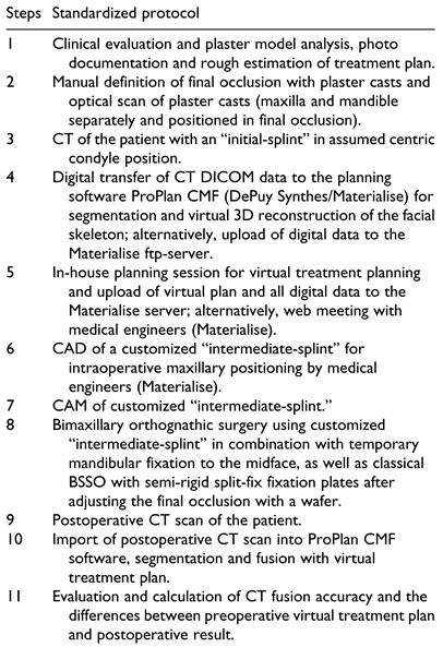
In this retrospective study, 35 consecutive patients underwent bimaxillary osteotomy for the correction of dentofacial deformities. Orthognathic surgery was performed in the Department for Oral and Maxillofacial Plastic Surgery of the Military Hospital Ulm. The study was approved by the Ethics Committee of the University of Ulm (approval no. 439/15) and was performed in compliance with the Helsinki Declaration (October 2013). The processes of treatment planning, surgery, and postoperative follow-up were standardized, as shown in
Table 1.
Planning Procedure
After clinical examination concerning vertical, sagittal, and horizontal facial dimensions, facial asymmetries, occlusal relationship, occlusal plane, overjet, overbite, maxillary and mandibular dental midline, gummy smile, chin and nose profile and lip configuration, photographs and plaster casts, which were articulated according to bite registration and face bow, were employed for haptic evaluation of the occlusal relationship. Based on this initial situation of the maxillary and mandible casts in habitual occlusion, an “initial-splint” was manufactured. Afterward, the casts were fixed in defined final occlusion. Based on this fixation, the “final-splint” was manufactured. In addition, the isolated casts of mandible and maxilla and splint fixed mandibular and maxillary casts in primary and final occlusion were laser surface scanned (Zenotec Scan S50, Wieland Dental). A high-resolution multi-slice computed tomography (CT) (Somatom definition, Siemens) of the entire skull and reconstruction in 0.5 to 1 mm slices was employed for 3D virtual planning. During CT scan, the patients wore aforementioned “initial-splint” in habitual occlusion. Afterward, virtual planning was performed using ProPlan CMF software (Materialise). After the DICOM data were imported into the software, the segmentation of the soft tissue, the skull, the mandible, and the upper skull (per definition upper skull was skull minus mandible) was performed. Next, the virtual skull model was orientated concerning the natural head position (NHP). NHP was defined by the facial midline, the Frankfurt horizontal plane, and the bipupilar plane. The orientation according to the mentioned planes was approved employing the segmented soft tissue, as well as the segmented bone model of the skull. In cases of facial asymmetries, the orientation was based on the best possible position. After manual alignment of the patient’s NHP, the STL files of the maxillary and mandibular casts were imported into the software and were fused with the maxilla and mandible by a semiautomatic fusion algorithm. The result obtained was a composite model of the mandible and the maxilla with a precise and high-resolution dental arch. By fusion of the scanned occlusion of the casts defined by the “initial-splint” the correct position of the mandible and the “initial-splint” during the CT scan could be checked again. Then the LeFort I and bilateral sagittal split osteotomies (BSSOs) were performed in the software virtually using the included semiautomatic osteotomy wizard. After the osteotomies, the STL file of the scan consisting of mandible and maxilla in final occlusion (defined by the “final-splint” in the articulator) was imported into ProPlan CMF software to fuse and register it to the maxilla first and second to the mandible. The maxilla and the 2 mandibular rami stayed in their original position, while the mandibular corpus moved in the position which was determined by the final occlusion. Now the monobloc, out of osteotomized maxilla and mandible, was moved into the final position according to the clinical and radiological evaluations. Final position was approved by checking the maxillary and mandibular position in relation to the upper skull in all 3 dimensions, the midline, the occlusal plane, the cant, the angulation of the incisors, the vertical position of the incisors in relation to the upper lip and the chin position. The time needed for the complete aforementioned virtual planning procedure was approximately 1.5 hours. It can be split into preparation for planning, which takes in 45 to 60 minutes for segmentation and fusion of the casts and another 30 to 40 minutes for the movements and adjustments of the jaws. After finalizing the planning process, the plan, the DICOM data of the CT, and the files of the optical scans of the casts were sent to Materialise using a secured ftp-server. Based on these data, the “intermediate-splint” that defined the new maxillary position was designed and manufactured by 3D printing.
Surgical Technique
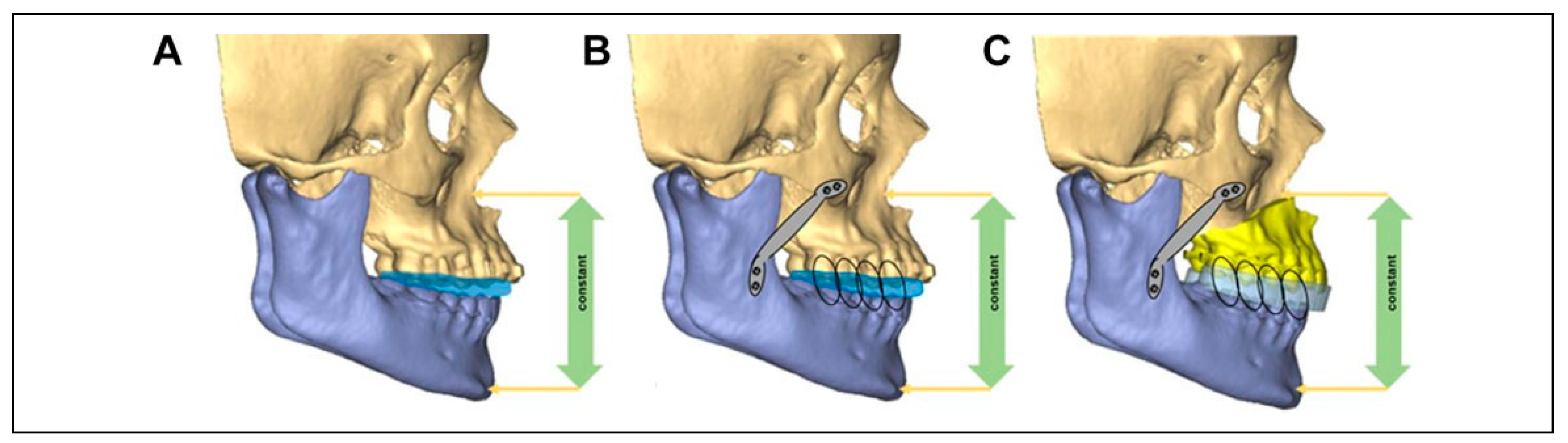
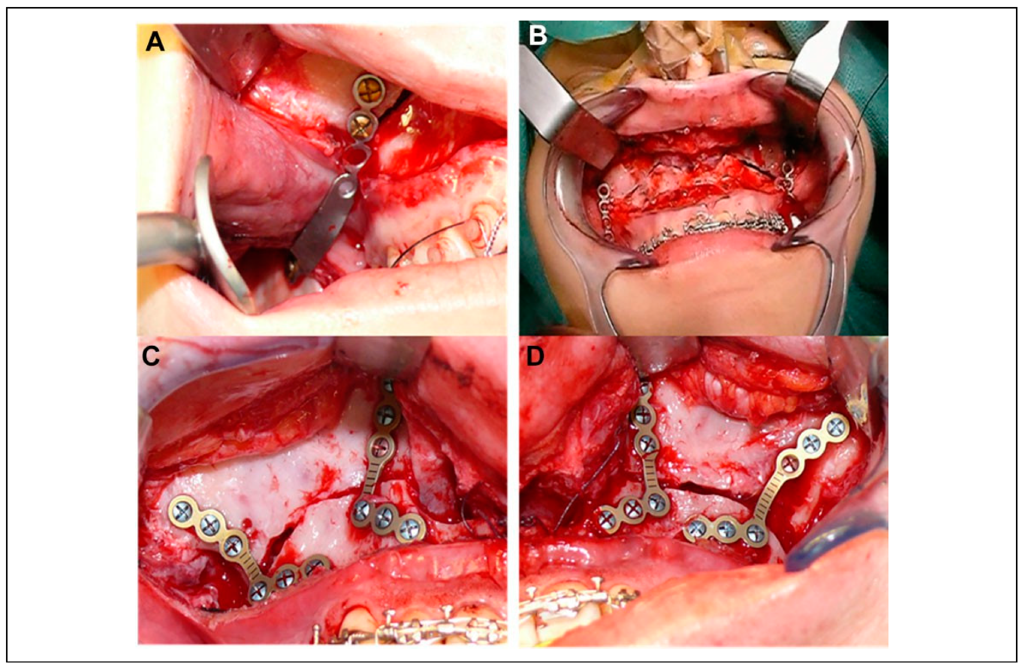
The operation started with the exposure of the maxilla and was followed by the bone cuts of a conventional LeFort I osteotomy. Instead of consecutively performing the down fracture with mobilization of the maxilla, the following intermediate step was implemented. The “initial-splint” was inserted and mandibulomaxillary fixation (MMF) was performed. Afterward, the mandible was exposed like for the BSSOs on both sides. Two L-shaped osteosynthesis plates were adapted passively from the mandibular ramus up to the zygomatic region cranial of the LeFort I osteotomy lines on each side. The plates were fixed with 2 mini-screws at the ramus and 2 mini-screws on the zygoma (
Figure 1B and
Figure 2A). The result was a fixed mandible in the exact same position as it was during the CT scan which was the basis for the 3D planning (
Figure 1A). Based on this mandibular position, the “intermediate-splint” was designed and manufactured before. The next step was the removal of the mandibular fixation plates and the “initial-splint.” LeFort I osteotomy and the mobilization of the maxilla were completed. This was followed by MMF with inserted CAD/CAM-generated “intermediate-splint.” Consequently, the 3D-planned transverse and sagittal movements of the maxilla were transferred to the operational site by the splint. To transfer the 3D-planned vertical positioning as well, the former fixed and then removed mandibular fixation plates were placed again at both sides of the mandibular ramus in alignment to the screw holes which were drilled during their initial fixation. Then the Mandibulo-Maxillary Complex (positioned by the CAD/ CAM “intermediate-splint”) was moved cranial, until both mandibular fixation plates could be aligned and re-fixated in the initial screw holes cranial of the LeFort I osteotomy line (
Figure 1C and
Figure 2B) again. Employing this technique, the transfer of the 3D-planned maxillary position could be achieved in all 3 dimensions without losing vertical control. The definitive osteosynthesis followed with 2 L-miniplates at first in the paranasal region on both sides while keeping the mandibular fixation plates in place. Afterward, the mandibular fixation plates were removed and additional L-miniplates in the zygomatic regions left and right were fixed (
Figure 2C and D). Mandibular positioning was afterward achieved after a standard BSSO, employing the “final-splint.” For fixation of the mandible, the semi-rigid split-fix osteosynthesis plates (DePuy Synthes) were used.
Study Intervention
A CT scan was performed preoperatively for diagnosis and 3D planning. Within 5 days after surgery, a second CT scan to control osteosynthesis and position of condyles while the patient was wearing the “final-splint” and mandibulo-maxillary elastics (MMF) was done. For validation of the method and analysis of the accuracy of the surgical results, the preoperative virtual plan was compared with the post-operative surgical result, using surface registration of the virtually planned final position of the maxilla and the post-operative position of the maxilla.
Postoperative Analysis
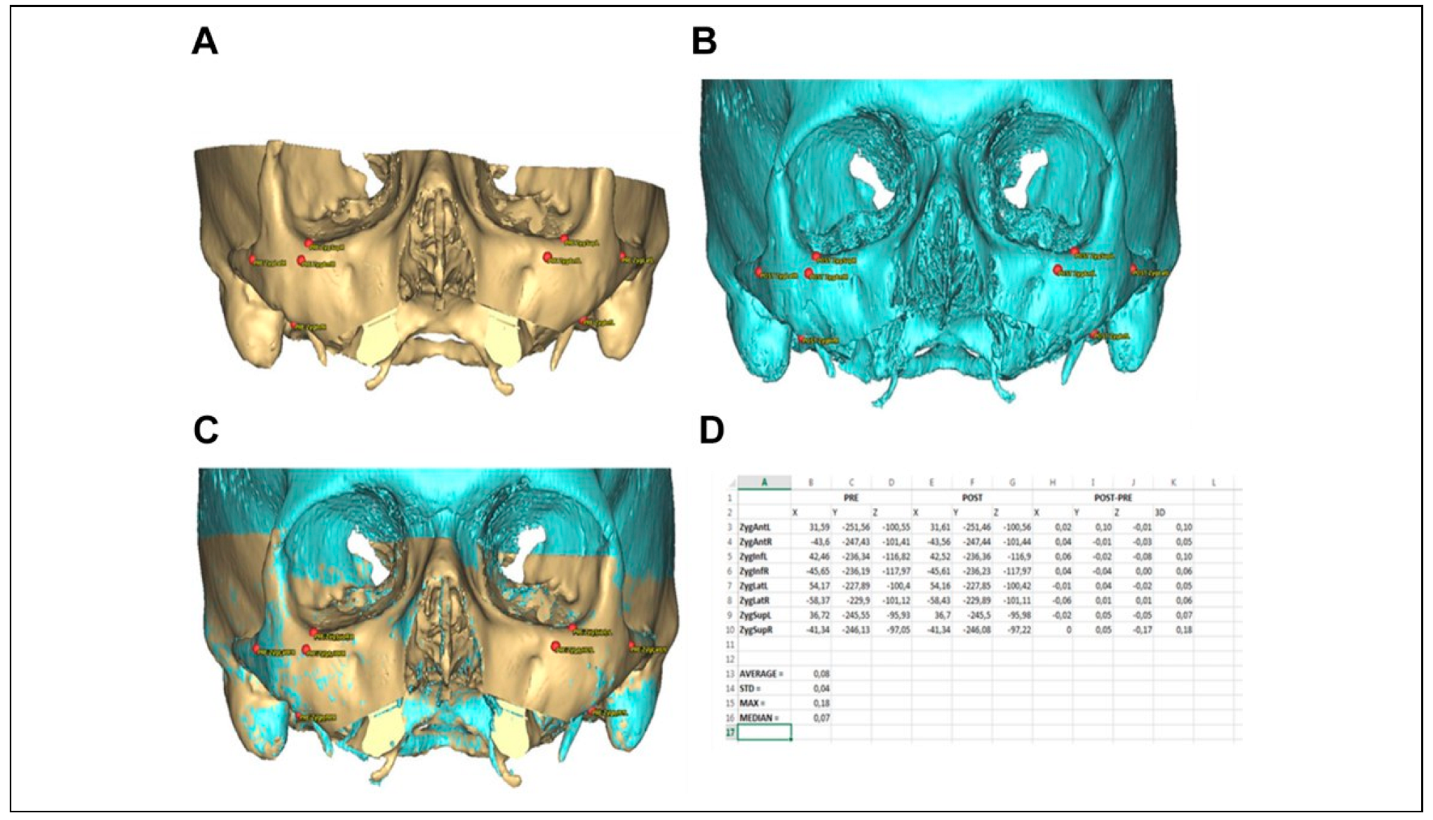
Segmentation of postoperative CT scans was performed according to the identical protocol as the segmentation of the preoperative CT scans. The segmented postoperative objects were imported into the ProPlan CMF software file which also contained the original preoperative and planned simulation. The registration of the segmented pre- and postoperative data sets was performed using the alignment tool in ProPlan CMF. This tool uses a global registration to align the postoperative skull base to the preoperative skull base in order to obtain the “NHP” as defined during the original surgical planning. This automated registration was fine-tuned by selecting focus regions or landmarks such as foramen magnum, orbit, and zygoma. Validation of the registration accuracy was performed by selecting 4 landmarks over each zygoma (superior, inferior, lateral, and anterior). The preoperative and postoperative positions of the 4 zygoma landmarks were compared and the difference was calculated in all 3 axes
X/
Y/
Z (
Figure 3). A maximum allowable variation of 0.5 mm between the preoperative and postoperative skull was used to account for small differences in segmentation or due to the scan protocol, difference in scan field of view and quality of both CTs. The median and maximum deviations were recorded for each patient data set. Final result of this step was 1 single ProPlan CMF file, in which there were aligned skulls (preoperative skull from the planning file and the postoperative skull), and 3 different positions for the maxilla: the preoperative position, the simulated position as defined during the planning procedure, and the postoperative maxillary position as defined from the postoperative CT scan. In order to compare the planned and the postoperative maxillary object in each case and in all 3 dimensions, the following 5 occlusal landmarks were used as invariable parameters:
For each of the 5 landmarks indicated on the planned maxillary object, a corresponding landmark in the preoperative position was generated as an exact copy. The planned position of each landmark on the maxilla was compared to the preoperative position of each corresponding landmark in the
X/
Y/
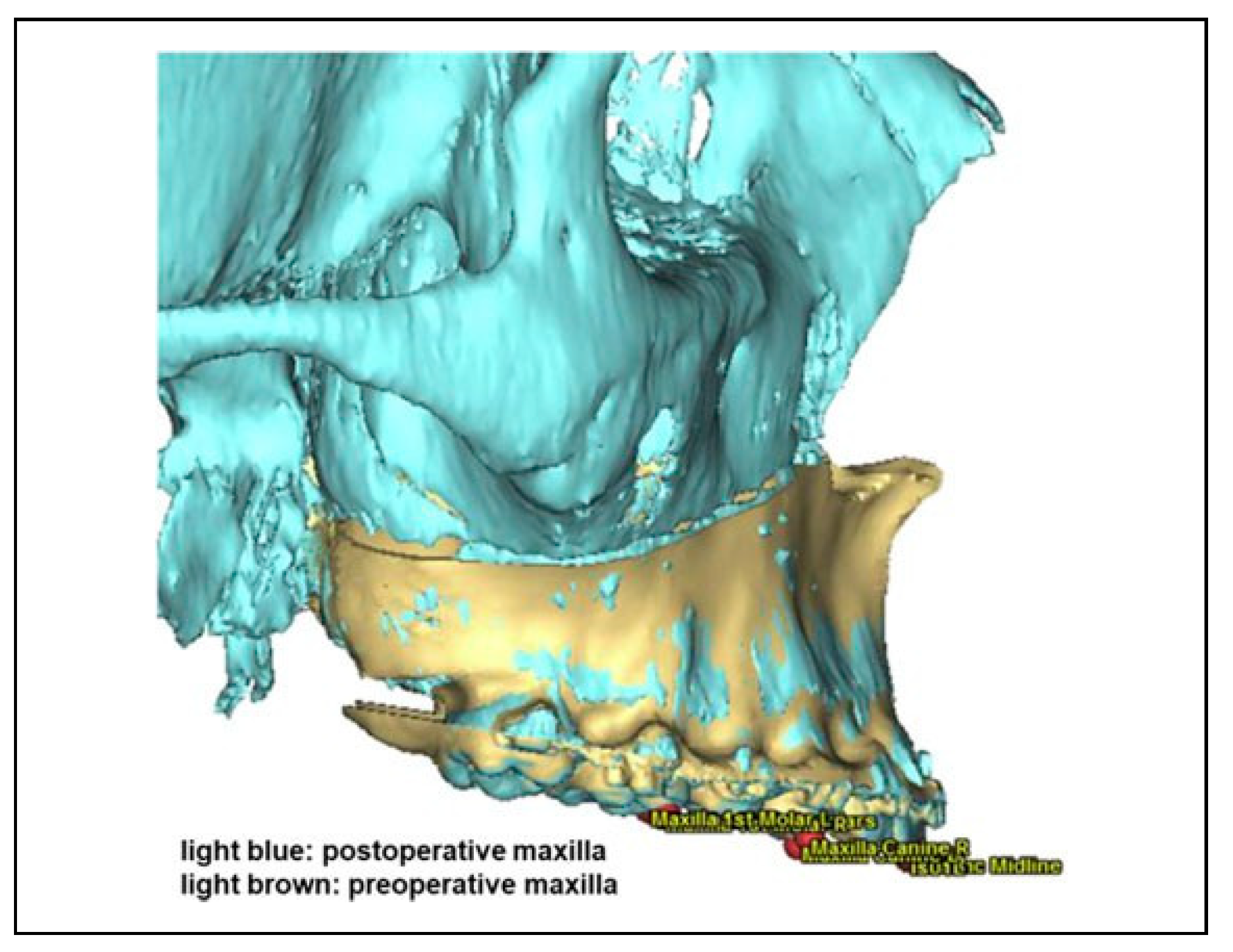
Z-directions. The preoperative maxilla with linked landmarks was then aligned to the postoperative maxilla using the alignment tool, an automatic global registration based on the bone volume. Once aligned, the software measured the difference and movements in X-, Y-, and Z-axis for each of the 5 points (
Figure 4). To calculate the difference between the postoperative situation and the planned intended movement of the maxilla, the following calculations had been made:
Planned movement: planned position minus preoperative position for X/Y/Z values of the 5 landmarks.
Surgical movement: postoperative position minus preoperative position for X/Y/Z values of the 5 landmarks.
Out of these two values, the difference between planned and achieved position was calculated for all 5 landmarks in all 3 axes X/Y/Z by surgical movement minus planned movement:
- –
The X-axis represents the direction right–left.
- –
The Y-axis represents the direction up–down.
- –
The Z-axis represents the direction anterior– posterior.
Specifics in the Split Maxilla Cases
In those cases where the maxilla was divided into 2 or 3 segments, a mechanical separation of the maxillary cast models was necessary. The individual segments were delineated on the plaster model and cut in different pieces. In most of the split maxilla cases, a sagittal separation between the incisors in region 11/21 was performed. However, an asymmetrical division or a corresponding division of individual jaw segments was also possible. A total of 3 segments were identified in the 3-piece maxilla cases. The saw-cut maxillary model was then fixed in the desired position of the individual segments on the mandible. Now the divided upper jaw was fixed again with plaster in the articulator according to the final position of the mandible. For intraoperative stabilization of the separated segments, a plastic holding palatal plate was manufactured by the dental technician. A new 3D scan of the split model was necessary to generate the split maxilla STL model. This STL object including the palatal holding plate was then superimposed with the initial planning CT data set in the ProPlan CMF software (
Figure 5A and B). The digital osteotomies were performed on CT data of the maxilla in the same configuration like that on the plaster model and all segments were then fused individually. After digital separation and repositioning of the segments in the divided upper jaw, the CAD/CAM intermediate-splint was created like in the one-piece maxilla cases before. The CAD/CAM splint of the split maxilla cases was fabricated in such a way that it was securely retained on the maxilla even when the clasp-supported palatal holding plate was in situ. For accuracy analyzation of the split maxilla cases, the 5 landmarks on the STL object of the scanned “split plaster model” were marked for evaluation as during the analyzation of the one-piece maxilla cases before (
Figure 5B). The individually separated upper jaw parts were then segmented and superimposed (including the landmarks) with the planned position in the preoperative planning and the postoperative CT images (
Figure 5C and D). By superimposing the different segments including the landmarks, the deviation from the planning and the surgical result could be compared. Only this intermediate step made it possible to calculate the distance of the planned displacement from the original maxillary position in mm for each individual landmark in relation to the original position in the preoperative “undivided maxilla.”
Statistical Analysis
Descriptive data analysis was completed using the software IBM SPSS. Kolmogorov-Smirnov test and Shapiro-Wilk test revealed that the distribution of the data was not homogeneous. Therefore, we analyzed the data using the median, maximum, minimum, range, and interquartile range. Additionally, the root mean square deviation (RMSD) was calculated to determine the degree of deviation between the examined methods. We considered that the absolute values are representing the absolute accuracy of the method, while the signed values are representing an under- (— value) or overcorrection (+ value) with regard to the preoperative plan in each plane. For statistical testing, Friedman’s 2-way analysis of variance by ranks and the Mann-Whitney U test were employed. Values of P ≤ .05 were considered significant and values of P ≤ .005 highly significant.
Results
A total of 35 patients (19 males and 16 females) were included in the study. Twenty-six operations were performed as bimaxillary interventions without additional segmentation of the maxilla, employing LeFort I osteotomy in the maxilla and a BSSO in the mandible. Six patients underwent an additional segmentation of the maxilla in 2 and 3 patients in 3 pieces. The median age was 25.37 years, with the youngest 18 years old and the oldest being 45 years of age. Regarding the absolute values, the deviation of the maxillary position between preoperative virtual plan and post-operative result calculated over all 35 cases, all 5 landmarks, and all 3 axes was median 0.99 mm (max = 4.48 mm, min = 0.01 mm, RMSD = 0.84 mm). The maximum deviation was shown in a patient of 3-piece segmentation of the maxilla.
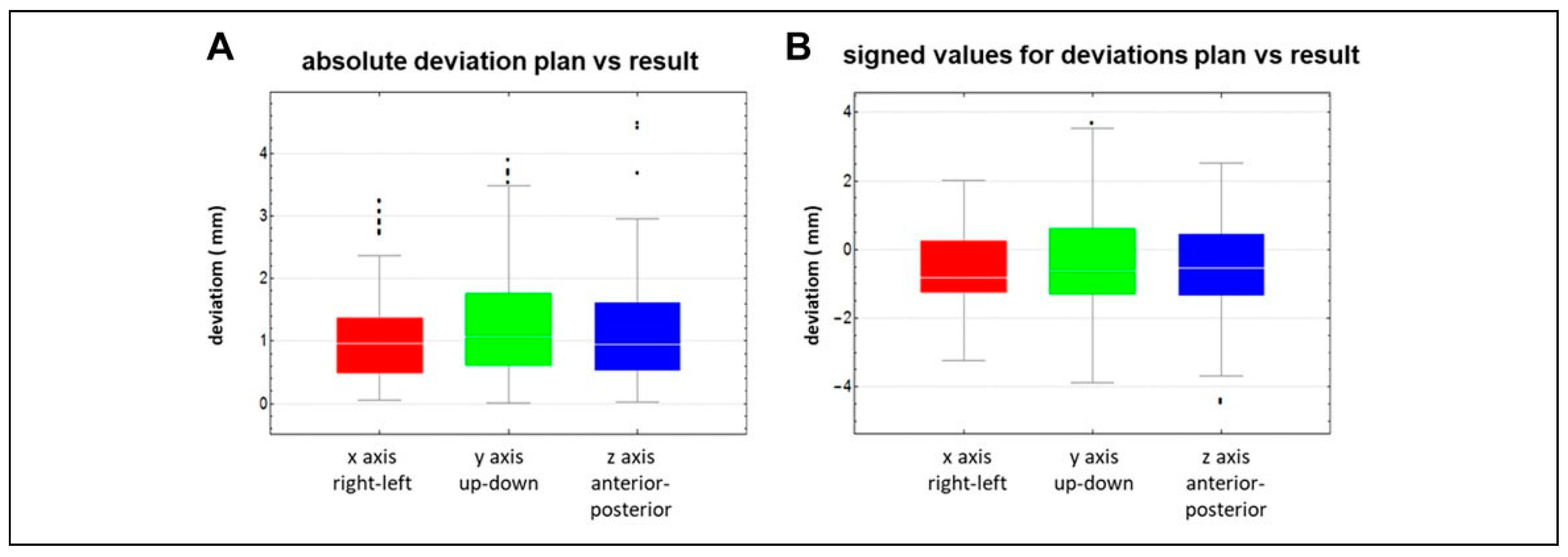
Considering the deviations with regard to the 3 axes
X/
Y/
Z calculated over all 35 cases and all 5 landmarks, the median deviation of the absolute values between plan and result was in the
X-axis (direction right–left) 0.96 mm (min = 0.06 mm, max = 3.24 mm, RMSD = 0.70 mm), in the
Y-axis (direction up–down) 1.06 mm (min = 0.01 mm, max = 3.89 mm, RMSD = 0.98 mm), and the
Z-axis (direction anterior– posterior) 0.94 mm (min = 0.02 mm, max = 4.48 mm, RMSD = 0.80 mm) (
Figure 6A). The deviations between
X-axis,
Y-axis, and
Z-axis showed no significant difference (
P = .293). Analyzing the measured deviations regarding all 5 occlusal landmarks with consideration of the 3 axes
X/
Y/
Z showed no statistical difference (
P = .349) either.
The deviation of the signed values of the maxillary position between preoperative plan and postoperative result calculated over all 35 cases, all 5 landmarks, and all 3 axes was median —0.62 mm (max undercorrection = —4.48 mm, max overcorrection = 3.67 mm, RMSD = 1.33 mm). The median deviation of the signed values with regard to the
X/
Y/
Z axes calculated over all 35 cases and all 5 landmarks were in the
X-axis —0.81 mm (max undercorrection = —3.24 mm, max overcorrection = 2.03 mm, RMSD = 1.09 mm), in the
Y-axis —0.61 mm (max undercorrection = —3.89 mm, max overcorrection = 3.67 mm, RMDS = 1.60 mm), and the
Z-axis —0.55 mm (max undercorrection = —4.48 mm, max overcorrection = 2.53 mm, RMSD = 1.27 mm) (
Figure 6B). No statistically significant difference could be seen between the 3 axes. Furthermore, there was no statistically significant difference regarding the 5 landmarks “with” or “without” consideration of the 3
X/
Y/
Z axes. All these aforementioned accuracy measurements are related to the accuracy of the fusion between the pre- and postoperative data sets as well.
The evaluation of the fusion accuracy in our cohort showed a very high accuracy with a median inaccuracy of 0.07 mm (maximum median inaccuracy of 0.34 mm in 1 case).
Separate Analysis of One-Piece Maxilla Cases and Segmented Split Maxilla Cases
Because the supposed more difficult procedure of segmentation of maxilla into 2 or even 3 pieces might influence the accuracy of the maxillary positioning, both groups were analyzed separately.
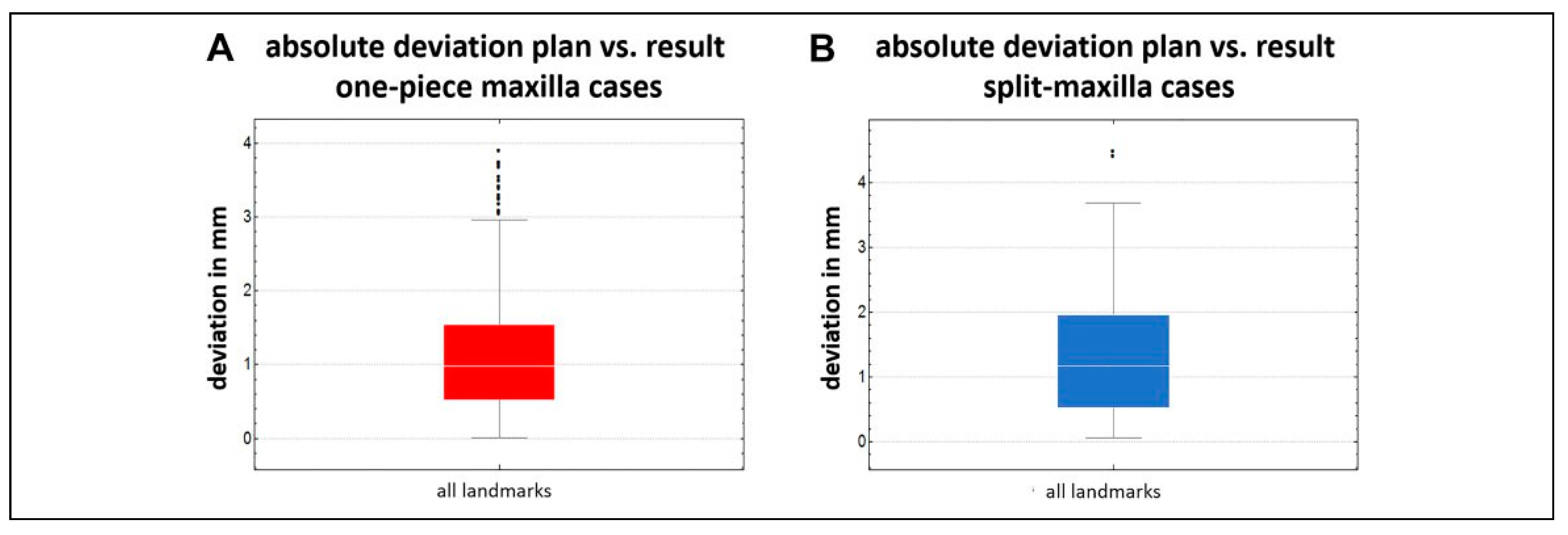
The absolute values of the deviation of the maxillary position between preoperative plan and postoperative result calculated over the 26 one-piece maxilla cases, all 5 land-marks, and all 3 axes was median 0.98 mm (max = 3.89 mm, min = 0.01 mm, RMSD = 0.81 mm) (
Figure 7A). In contrast, the same evaluation of the 9 split maxilla cases showed a median inaccuracy of 1.13 mm (max = 4.48 mm, min = 0.06 mm, RMSD = 0.91 mm). This inaccuracy seems to be tendentially higher, but without statistical significance (
P = .251) (
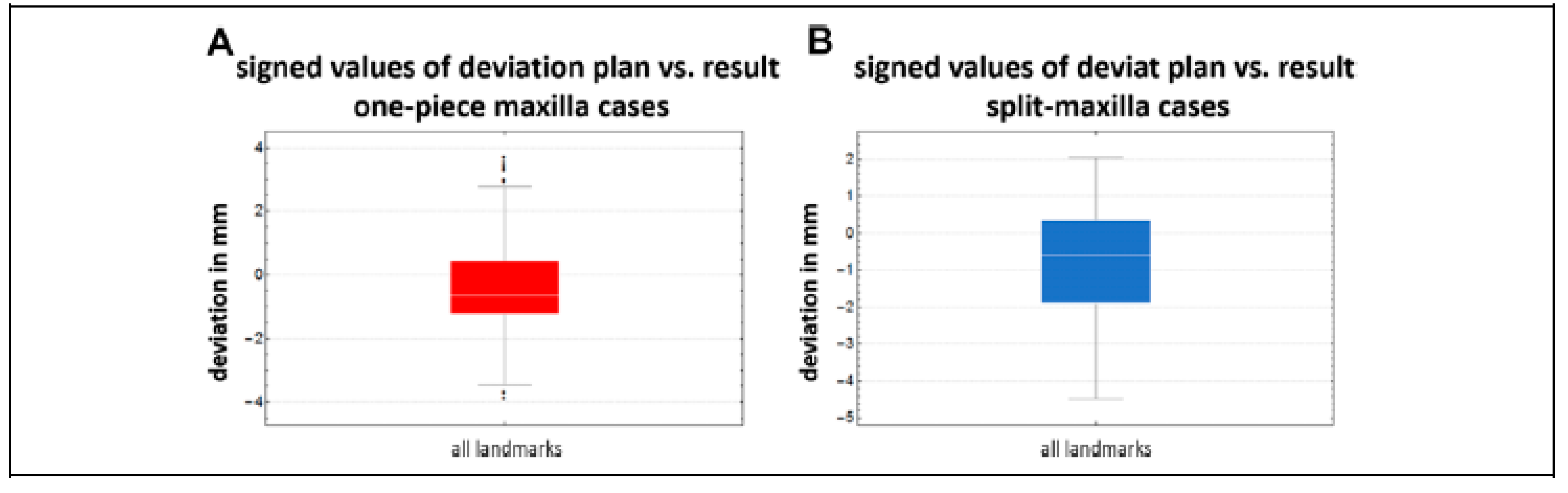
Figure 7B). The deviation of the signed values of the maxillary position between preoperative plan and post-operative result calculated over the 26 one-piece cases, all 5 landmarks, and all 3 axes was median —0.65 mm (max overcorrection = 3.67 mm, max undercorrection = —3.89 mm, RMSD = 1.33 mm) (
Figure 8A). The corresponding analysis of the split maxilla cases showed a median deviation of —0.61 mm (max overcorrection = 2.03 mm, max undercorrection = —4.48 mm, RMSD = 1.35 mm) (
Figure 8B). Again, there is no significant difference between both groups. The comparison of the deviation considering the 3
X/
Y/
Z axes showed no significant difference between the one-piece maxilla and the split maxilla group either.
Discussion
The potential benefits and limitations of an integrated 3D virtual approach for the treatment of the patient with a maxillo-facial deformity are discussed comprehensively.[
6,
7,
9,
11,
12,
16,
17,
18,
19]
In this study, we evaluated the accuracy of virtually 3D-planned maxillary positioning using CAD/CAM “intermediate-splints” in combination with temporary mandibular fixation for creation of a new intraoperative vertical reference plane. Whether the plan itself achieved its expected esthetical or functional result has not been considered. The accuracy in this study showed with a median deviation plan versus result of 0.99 mm a high precision of the transfer of the preoperative virtual plan into reality. Just in 2 cases, a maximum deviation >2.5 to 4.5 mm could be seen.
Therefore, the authors believe that the technique described in this article is precise and the median deviation may not really show clinical relevance. Nevertheless, these data reveal the limits of the technique as well. The case with the highest discrepancy was a case of a cleft patient in which a segmented 3-piece maxilla was performed. This may show the difficulty of operating such cases.
There was no significant difference in accuracy regarding the 3 axes X/Y/Z over all cases. This result proves that by employing temporary mandibular fixation, even vertical positioning can be achieved by the same high accuracy as transverse and sagittal positioning. This was not expected, because vertical positioning is supposed to be most difficult by conventional wafer-based maxillary positioning, due to the loss of vertical control. Due to a missing control group which was also operated with CAD/CAM “intermediate-splints” but without temporary mandibular fixation we cannot statistically prove, but the authors assume that without temporary mandibular fixation for vertical control during maxillary positioning, discrepancy between virtual plan and postoperative result may be much higher or at least will show a bigger range.
It is very difficult to compare the results of accuracy studies in orthognathic surgery 1:1. This is because different evaluation methods were employed, especially when accuracy evaluation was performed on 2D imaging only. But in the case of this study, there is 1 study which is 1:1 comparable. The study of Heufelder et al[
5] which evaluated the accuracy of waferless maxillary positioning and employed the same evaluation method as in this study. The accuracy in our study showed more than the double of inaccuracy in comparison to waferless maxillary positioning (this study: median deviation plan vs result 0.99 mm, maximum deviation 4.48 mm; Heufelder et al[
5]: median deviation 0.39 mm, maximum deviation 2.02 mm). These results suggest that the future may lie in waferless maxillary positioning.
Deviations in all measured regions (molar-, canine-, incisor region) were almost equal. There were no signs that, for example, posterior movements (region 16 or 26) are less accurate than anterior movements (region 11/21). This positive result was not expected by the authors because it must be assumed that a posterior impaction of the maxilla is the most difficult movement to be achieved and maxillary posterior impaction was necessary in more than half of the patients included in this study.
In all axes, a tendency for undercorrection compared to the plan could be seen. An explanation for this trend is not obvious for the authors. The most likely reason is by accident because this trend was statistically not significant.
There is high precision of the evaluation in this study, since fusion inaccuracy (planning vs result) was median 0.07 mm only. Assessing the accuracy of image fusion between preoperative plan and postoperative result reduces the measurement error significantly. Except in the study of Heufelder et al[
5] these values have not been evaluated in previous studies, despite of high importance.[
9,
10,
13,
17,
20] Therefore, errors or falsification of the results by fusion can be excluded in our investigation. Furthermore, for each landmark indicated on the planned maxillary object, a corresponding landmark in the preoperative position was generated by ProPlan CMF automatically. This means that landmarks were not marked manually on the various data sets. Instead, the landmarks for our measurements were only fixed once per patient, then copied 1:1 and moved with the jaw without changing the position of the landmarks relative to the teeth. Another advantage of this study is that the postoperative results were analyzed by the same software which has been used for virtual planning. This reduces discrepancies caused by converting data sets for the use in different software.[
21] It was interesting that the supposed more difficult procedures of segmentation of maxilla in 2 or even 3 pieces did not influence the accuracy of the maxillary positioning significantly. Unfortunately, no comparison with other studies can be made, due to a lack of studies focusing on this issue.
One big disadvantage of temporary mandibular fixation for maxillary positioning is the additional time which is needed to adapt and to remove the mandibular fixation plates. Of course, this was not the aim of this investigation and the additional time for adaption and removal of the mandibular fixation plates was not measured. Nevertheless, it can be expected that at least around 30-minute extra time is needed for this additional procedure for which of course also additional costs arise.[
22] A second disadvantage was the additional cost for the planning software and for printing the CAD/CAM splint. However, comparing the costs to waferless maxillary positioning using patient-specific guides and implants, the costs of this investigated technique is far below.
 ,
, 

