
Research Progress on Convective Heat Transfer Characteristics of Supercritical Fluids in Curved Tube

 , ,
, ,  and
and 
Abstract
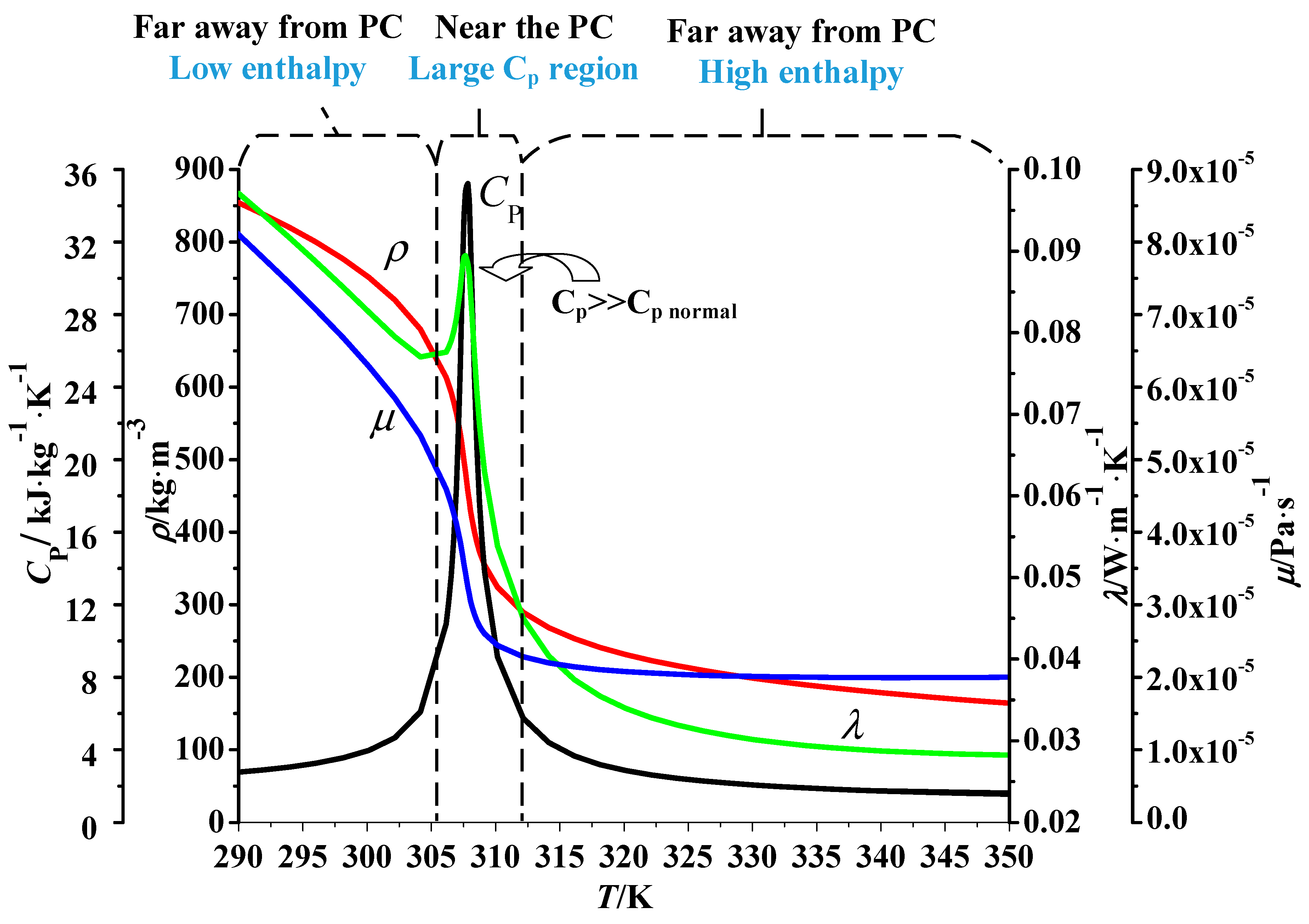
1. Introduction
2. Materials and Methods
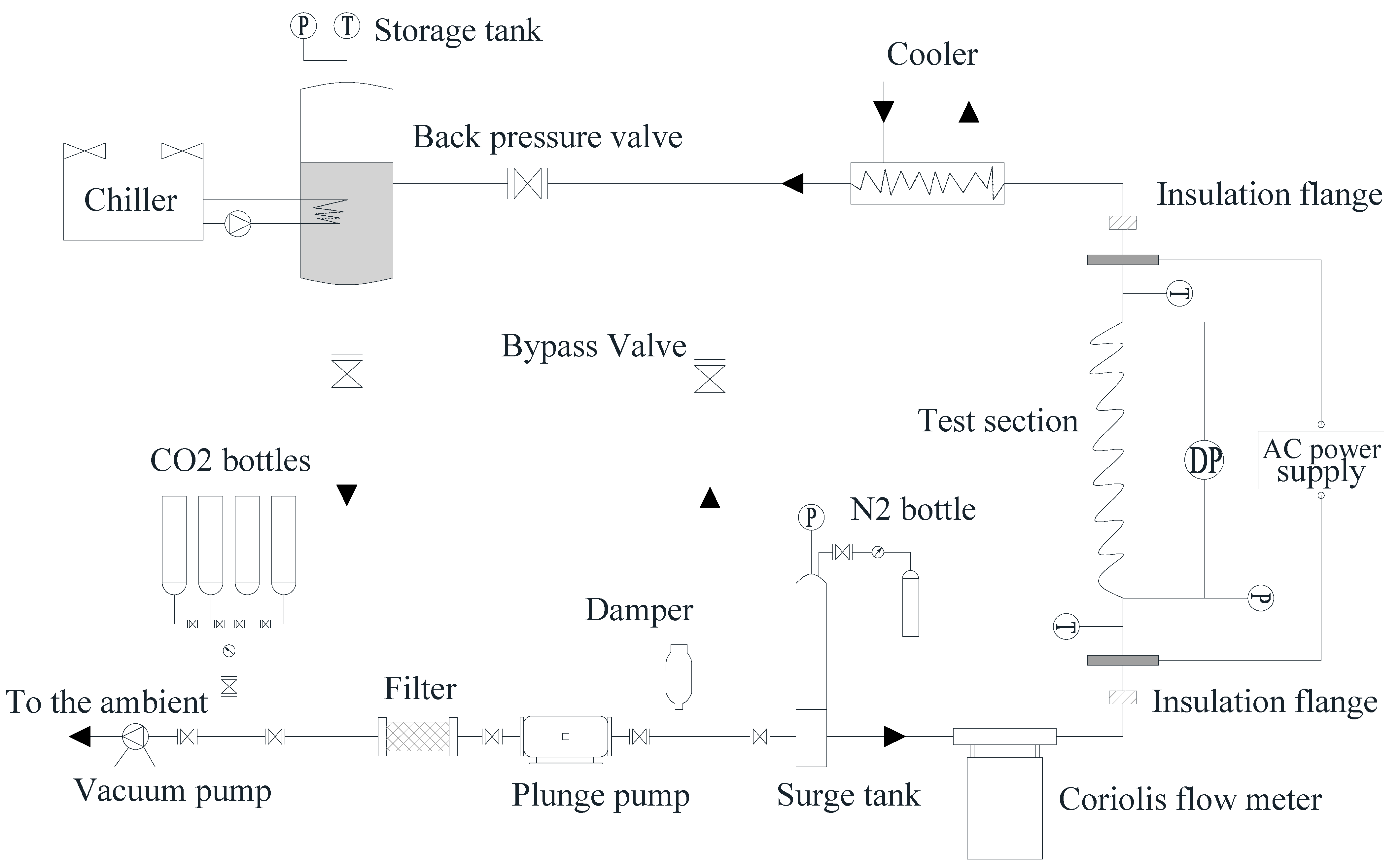
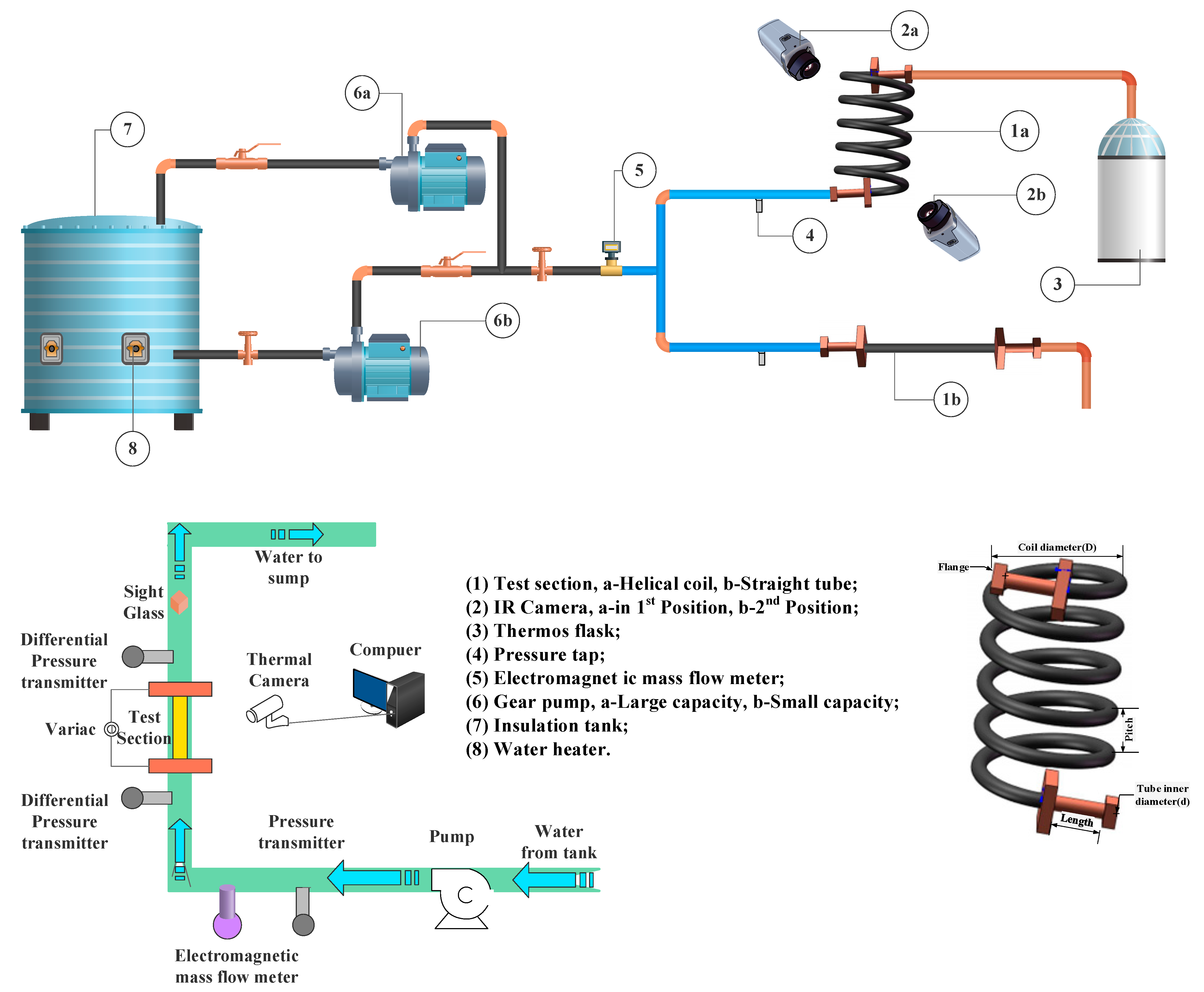
2.1. Experimental Study
2.2. Numerical Study

| Author | Section Type | Boundary Condition | Flow Regime | Working Fluid | Turbulent Model | Validation |
|---|---|---|---|---|---|---|
| Li et al. [81] | Curved pipe | Constant wall temperature | δ = 0.05, N = 1 | H2O | RNG k-ε | Compare Nu |
| Zhao et al. [29] | Helically coiled tube | Constant wall heat flux | d = 7.5 mm, D = 200, 400 mm, b = 8 mm, l = 2281 mm | H2O | SST k-ω | Compare h |
| Xu et al. [60] | Helically coiled tube | Constant wall heat flux | d = 9 mm, 2R = 283 mm, b = 32 mm, l = 5500 mm | CO2 | RNG k-ε | Compare Tw |
| Yang [30,83] | Helically coiled tube | Constant wall heat flux | d = 4 mm, D = 40 mm, b = 10 mm, l = 2000 mm | CO2 | RNG k-ε | Compare h |
| Li et al. [79] | Helically coiled tube | Coupled boundary condition | d = 9 mm, D = 283 mm, b = 32 mm, l = 5500 mm | CO2 | SST k-ω | Compare h and Tw |
| Liu et al. [19] | Helically coiled tube | Constant wall heat flux | d = 9 mm, D = 283 mm, P = 32 mm, l = 5500 mm | CO2 | SST k-ω | Compare h, Tw and Tb |
| Zhao et al. [91] | Helically coiled tube | Coupled boundary condition | d = 6 mm, D = 80 mm, b = 12 mm, N = 10 | CO2 | AKN k-ε | Compare h |
| Zhang et al. [92] | Helically coiled tube | Constant wall heat flux | d = 9 mm, D = 283 mm, P = 32 mm, l = 5500 mm | CO2 | SST k-ω | Compare K |
| Ciofalo et al. [93] | Toroidal pipe and helically coiled pipe | Wall temperature linearly increasing along flow direction | d = 0.9, λ = 0.4 | -- | -- | -- |
| Wang et al. [80] | Constant wall temperature | d = 20 mm, D = 300 mm, b = 30 mm, N = 11 | Methane | RSM | Compare h | |
| Liang et al. [78] | Concave, heated, 90° bend | Coupled boundary condition | square tube, hydraulic diameter d = 2 mm, D = 100 mm | n-Decane | -- | Compare Nu |
| Yang et al. [61] | Helix tube gas cooler | Coupled boundary condition | d = 10 mm | CO2 | k-ω | -- |
| Li et al. [82] | Curved tubes | The true distribution of heat flux of scramjet | d = 12 mm, D = 300 mm, l = 4500 mm | China No.3 aviation kerosene | RNG k-ϵ | Compare Nu |
| Liu et al. [32] | Helically coiled tube | Constant wall heat flux | d = 4–16 mm, D = 150–283 mm, l = 5500 mm, N = 5 | CO2 | SST k-ω | Compare h and T |
| Zhang et al. [92] | Helically coiled tube | Constant wall heat flux | d = 9 mm, D = 283 mm, P = 32 mm, l = 5500 mm | CO2 | SST k-ω | Compare h |
| Yi et al. [94] | Serpentine micro-tube | Constant wall heat flux | d = 1 mm, D = 8 mm, l = 7Rπ mm | CO2 | RNG k-ε | Compare Tw |
| Sun et al. [54] | U-tube | Constant wall heat flux | d = 1.82 mm, D = 30 mm, | Aviation kerosene | LES | Compare Tw |
| Li et al. [95] | Helically coiled channels | One-side heating with constant wall heat flux | d = 9 mm, D = 283 mm, b = 32 mm, l = 5500 mm | CO2 | SST k-ω | Compare h and Tw |
| Jiang et al. [96,97] | Helically coiled tube | Constant wall heat flux | d = 12 mm, D = 70 mm, b = 32 mm, l = 1222 mm | s-R1234ze€ | SST k-ω | Compare h |
| Huang et al. [98] | U-tubes | Constant wall heat flux | d = 1.82 mm, D= 40 mm | CO2 | Standard k-ε | Compare Tw |
| Luo et al. [99] | Helically coiled heat exchangers | Convective heat transfer | d = 3 mm, D = 40 mm, P = 15 mm | Air and n-decane | RNG k-ε | Compare Nu |
| Bai et al. [100] | Serpentine tube | Constant wall heat flux | d = 15 mm, D = 100 mm | LNG | SST k-ω | Compare Tw |
| Zhang et al. [101] | Helically coiled tube | Constant wall heat flux | d = 9 mm, 2R = 150–283 mm, b = 32 mm, l = 5500 mm | CO2 | SST k-ω | Compare Tw and Tb |
| Cui et al. [86] | Serpentine channel | Constant wall heat flux | d = 1.8 mm, D = 3.62 mm | CO2 | SST k-ω | Compare h |
| Li et al. [102] | Helically coiled tube | One-side heating with constant wall heat flux | d = 9 mm, 2R = 283 mm, b = 32 mm, l = 5340 mm | Water | RNG k-ε | Compare Tw and Tb |
3. Heat Transfer Characteristics of Supercritical Fluid in Curved Tubes
3.1. The Effect of Buoyancy Force on Circumferential Distribution
3.2. The Effect of Flow Direction on the Axial Direction
4. Future Work and Prospect
5. Conclusions
- Experimental and simulation studies show that the effect of working conditions on the heat transfer of supercritical fluid flow in curved tubes is basically the same as that in straight tubes: as the mass flow rate decreases, the pressure and heat flow density increase and the heat transfer coefficient decreases.
- The experimental study provides basic data for the quantitative concept and simulation validation of supercritical fluids in curved tubes. However, the significant three-dimensional characteristics make the popular scattered-point measurement method deficient in obtaining the overall heat transfer performance of supercritical fluids in curved tubes. In the future, advanced thermal imaging technologies should be intentionally applied in this field.
- By analyzing the cross-sectional vortex vector diagram, temperature, velocity and turbulent kinetic energy cloud diagrams, scholars concluded that the curved-tube circumferential heat transfer is influenced by centrifugal force, centrifugal buoyancy force, and gravitational buoyancy force. According to their theoretical analyses, a criterion for determining the relative magnitude of the buoyancy force and centrifugal force is developed. However, most simulation studies focus on the overall performance of curved tubes, ignoring the absolute advantage of simulation in gaining insight into the physical properties’ distribution and the flow structure in the boundary layer of the fluid.
- There is no consensus on the heat transfer correlation of supercritical fluids in curved tubes. On the one hand, it is because the criteria for determining the buoyancy force in curved tubes are uncertain; on the other hand, it is because the structure of curved tubes is more complicated than that of straight tubes, and the form of the structural parameters in the correlations is not yet settled.
- Curved tubes can enhance heat transfer and suppress deterioration effectively. However, the heat transfer in curved tubes has two undesired features: instability of heat transfer and uneven circumferential heat transfer. To suppress the above two features, the coupling of curved tubes and rough elements to enhance supercritical fluid heat transfer will be a hot spot for future research.
Author Contributions
Funding
Data Availability Statement
Conflicts of Interest
Nomenclature
| b | coil pitch divided by 2π [mm] |
| Bo* | non-dimensional buoyancy force |
| Bu | non-dimensional buoyancy force Bu = |
| cp | specific heat (J/kg⋅K) |
| d | tube diameter [mm] |
| D | curvature diameter [mm] |
| Dn | Dean number |
| g | gravitational acceleration (m/s2) |
| G | mass flux [kg/(m2⋅s)] |
| Gr* | Grashof number |
| Grashof number | |
| h | heat transfer coefficient [W/(m2⋅K)] |
| l | length of tube [mm] |
| m | mass flow rate [kg/s] |
| Nu | Nusselt numbers |
| p | pressure [MPa] |
| q | heat flux [W/m2] |
| Re | Reynolds number |
| Ri | Richardson number |
| Si | |
| T | temperature [K] |
| average temperature [K] | |
| u | velocity [m/s] |
| Greek symbols | |
| δ | curvature ratio [a/D] |
| α | global azimuthal angle around the curvature axis [o] |
| λ | thermal conductivity [W/(m⋅K)] |
| β | dip angle [o] |
| μ | dynamic viscosity [Pa/s] |
| ρ | density [kg/m3] |
| Subscripts | |
| b | bulk fluid |
| i | inlet |
| HCT | helically coiled tube |
| o | outlet |
| w | wall |
| Abbreviations | |
| DNS | direct numerical simulation |
| LES | large-eddy simulation |
| PC | pseudo-critical temperature |
| RANS | Reynolds averaged Navier–Stokes |
References
- Mao, S.; Zhou, T.; Wei, D.; Liu, W.; Zhang, Y. Heat transfer characteristics of supercritical water in channels: A systematic literature review of 20 years of research. Appl. Therm. Eng. 2021, 197, 117403. [Google Scholar] [CrossRef]
- Nieuwenhuyse, J.N.; Lecompte, S.; Paepe, M.D. Current status of the thermohydraulic behavior of supercritical refrigerants: A review. Appl. Therm. Eng. 2023, 218, 119201. [Google Scholar] [CrossRef]
- Sun, X.; Meng, H. Large eddy simulations and analyses of hydrocarbon fuel heat transfer in vertical upward flows at supercritical pressures. Int. J. Heat Mass Transf. 2021, 170, 120988. [Google Scholar] [CrossRef]
- Li, L.; Jiang, W.-Q.; Li, Y.; Su, S.-Y.; Shi, J.-F.; Yang, F. Analysis and prediction of heat transfer deterioration of supercritical pressure cryogenic methane in a vertical tube. Int. J. Heat Mass Transf. 2021, 180, 121824. [Google Scholar] [CrossRef]
- Xu, J.; Zhang, H.; Zhu, B.; Xie, J. Critical supercritical-boiling-number to determine the onset of heat transfer deterioration for supercritical fluids. Sol. Energy 2020, 195, 27–36. [Google Scholar] [CrossRef]
- Rahman, M.M.; Dongxu, J.; Beni, M.S.; Hei, H.C.; He, W.; Zhao, J. Supercritical water heat transfer for nuclear reactor applications: A review. Ann. Nucl. Energy 2016, 97, 53–65. [Google Scholar] [CrossRef]
- Schulenberg, T.; Leung, L.K.H.; Oka, Y. Review of R&D for supercritical water cooled reactors. Prog. Nucl. Energy 2014, 77, 282–299. [Google Scholar]
- Bazargan, M.; Fraser, D. Heat Transfer to Supercritical Water in a Horizontal Pipe: Modeling, New Empirical Correlation, and Comparison Against Experimental Data. J. Heat Transf. 2009, 131, 061702. [Google Scholar] [CrossRef]
- Pioro, I.L.; Duffey, R.B. Experimental heat transfer in supercritical water flowing inside channels (survey). Nucl. Eng. Des. 2005, 235, 2407–2430. [Google Scholar] [CrossRef]
- Shitsi, E.; Debrah, S.K.; Agbodemegbe, V.Y.; Ampomah-Amoako, E. Flow Instability in Parallel Channels with Water at Supercritical Pressure: A Review. World J. Eng. Technol. 2018, 6, 128–160. [Google Scholar] [CrossRef]
- Zhang, X.R.; Yamaguchi, H. An experimental study on evacuated tube solar collector using supercritical CO2. Appl. Therm. Eng. 2008, 28, 1225–1233. [Google Scholar] [CrossRef]
- He, J.C.; Dang, C.B.; Hihara, E. Experimental investigation of heat transfer to supercritical R245fa flowing vertically upward in a circular tube. Int. J. Heat Mass Transf. 2018, 127, 286–295. [Google Scholar] [CrossRef]
- He, J.C.; Dang, C.B.; Hihara, E. Supercritical heat transfer characteristics of R1233zd(E) in vertically upward flow. Int. J. Heat Mass Transf. 2018, 127, 497–505. [Google Scholar] [CrossRef]
- Tao, Z.; Cheng, Z.; Zhu, J.; Lin, D.; Wu, H. Large eddy simulation of supercritical heat transfer to hydrocarbon fuel. Int. J. Heat Mass Transf. 2018, 121, 1251–1263. [Google Scholar] [CrossRef]
- Cheng, Z.; Tao, Z.; Zhu, J.; Wu, H. Diameter effect on the heat transfer of supercritical hydrocarbon fuel in horizontal tubes under turbulent conditions. Appl. Therm. Eng. 2018, 134, 39–53. [Google Scholar] [CrossRef]
- Fu, Y.; Wen, J.; Tao, Z.; Xu, G.; Huang, H. Experimental research on convective heat transfer of supercritical hydrocarbon fuel flowing through U-turn tubes. Appl. Therm. Eng. 2017, 116, 43–55. [Google Scholar] [CrossRef]
- Wen, J.; Huang, H.; Jia, Z.; Fu, Y.; Xu, G. Buoyancy effects on heat transfer to supercritical pressure hydrocarbon fuel in a horizontal miniature tube. Int. J. Heat Mass Transf. 2017, 115, 1173–1181. [Google Scholar] [CrossRef]
- Urbano, A.; Nasuti, F. Conditions for the occurrence of heat transfer deterioration in light hydrocarbons flows. Int. J. Heat Mass Transf. 2013, 65, 599–609. [Google Scholar] [CrossRef]
- Liu, X.; Xu, X.; Liu, C.; Ye, J.; Li, H.; Bai, W.; Dang, C. Numerical study of the effect of buoyancy force and centrifugal force on heat transfer characteristics of supercritical CO2 in helically coiled tube at various inclination angles. Appl. Therm. Eng. 2017, 116, 500–515. [Google Scholar] [CrossRef]
- Zhang, S.; Xu, X.; Liu, C.; Dang, C. A review on application and heat transfer enhancement of supercritical CO2 in low-grade heat conversion. Appl. Energy 2020, 269, 114962. [Google Scholar] [CrossRef]
- Xie, G.; Xu, X.; Lei, X.; Li, Z.; Li, Y.; Sunden, B. Heat transfer behaviors of some supercritical fluids: A review. Chin. J. Aeronaut. 2020, 35, 290–306. [Google Scholar] [CrossRef]
- Xu, W.; Li, Y.; Wang, Y.; Li, M.; Zhao, J.; Li, M.; Tian, H. Experimental investigations on cooling heat transfer of CO2-lubricant mixtures in horizontal tubes at supercritical pressure: A review. Int. J. Refrig. 2022, 139, 168–179. [Google Scholar] [CrossRef]
- Shitsi, E.; Debrah, S.K.; Agbodemegbe, V.Y.; Ampomah-Amoako, E. Performance of Heat Transfer Correlations Adopted at Supercritical Pressures: A Review. World J. Eng. Technol. 2018, 6, 241–267. [Google Scholar] [CrossRef]
- Tian, R.; Xu, Y.; Shi, L.; Song, P.; Wei, M. Mixed convection heat transfer of supercritical pressure R1234yf in horizontal flow: Comparison study as alternative to R134a in organic Rankine cycles. Energy 2020, 205, 118061. [Google Scholar] [CrossRef]
- Lau, K.T.; Khan, S.A.; Eze, C.; Tan, B.; Zhao, J. Numerical investigation on deteriorated heat transfer of supercritical water flowing upward in tubes with variable cross-sectional geometries. Int. Commun. Heat Mass Transf. 2022, 136, 106203. [Google Scholar] [CrossRef]
- Deev, V.; Kharitonov, V.; Baisov, A.; Churkin, A. Heat transfer characteristics of water under supercritical conditions. Int. J. Therm. Sci. 2022, 171, 107238. [Google Scholar] [CrossRef]
- Gharehdaghi, S.; Moujaes, S.F.; Nejad, A. Thermal-fluid analysis of a parabolic trough solar collector of a direct supercritical carbon dioxide Brayton cycle: A numerical study. Sol. Energy 2021, 220, 766–787. [Google Scholar] [CrossRef]
- Viswanathan, K.; Krishnamoorthy, G. The effects of wall heat fluxes and tube diameters on laminar heat transfer rates to supercritical CO2. Int. Commun. Heat Mass Transf. 2021, 123, 105197. [Google Scholar] [CrossRef]
- Zhao, H.J.; Li, X.W.; Wu, X.X. Numerical investigation of supercritical water turbulent flow and heat transfer characteris-tics in vertical helical tubes. J. Supercrit. Fluids 2017, 127, 48–61. [Google Scholar] [CrossRef]
- Yang, M. Numerical study of the heat transfer to carbon dioxide in horizontal helically coiled tubes under supercritical pressure. Appl. Therm. Eng. 2016, 109, 685–696. [Google Scholar] [CrossRef]
- Xu, X.; Liu, C.; Dang, C.; Wu, Y.; Liu, X. Experimental investigation on heat transfer characteristics of supercritical CO2 cooled in horizontal helically coiled tube. Int. J. Refrig. 2016, 67, 190–201. [Google Scholar] [CrossRef]
- Liu, X.X.; Xu, X.X.; Liu, C.; Bai, W.; Dang, C. Heat transfer deterioration in helically coiled heat exchangers in trans-critical CO2 Rankine cycles. Energy 2018, 147, 1–14. [Google Scholar] [CrossRef]
- Inagaki, Y.; Koiso, H.; Takumi, H.; Ioka, I.; Miyamoto, Y. Thermal hydraulic study on a high temperature gas gas-heat exchanger with heli-cally coiled tube bundles. Nucl. Eng. Des. 1998, 185, 141–151. [Google Scholar] [CrossRef]
- Taklifi, A.; Aliabadi, A.; Hanafizadeh, P.; Akhavan-Behabadi, M.A. Effect of inclination on frictional pressure drop of supercritical water flows in internally ribbed tubes: An experimental study. J. Supercrit. Fluids 2017, 125, 56–65. [Google Scholar] [CrossRef]
- Li, Z.; Wu, Y.; Tang, G.; Lu, J.; Wang, H. Numerical analysis of buoyancy effect and heat transfer enhancement in flow of supercriti-cal water through internally ribbed tubes. Appl. Therm. Eng. 2016, 98, 1080–1090. [Google Scholar] [CrossRef]
- Xu, K.K.; Tang, L.J.; Meng, H. Numerical study of supercritical-pressure fluid flows and heat transfer of methane in ribbed cooling tubes. Int. J. Heat Mass Transf. 2015, 84, 346–358. [Google Scholar] [CrossRef]
- Li, Z.; Wu, Y.; Tang, G.; Zhang, D.; Lu, J. Comparison between heat transfer to supercritical water in a smooth tube and in an inter-nally ribbed tube. Int. J. Heat Mass Transf. 2015, 84, 529–541. [Google Scholar] [CrossRef]
- Li, Z.; Lu, J.; Tang, G.; Liu, Q.; Wu, Y. Effects of rib geometries and property variations on heat transfer to supercritical water in in-ternally ribbed tubes. Appl. Therm. Eng. 2015, 78, 303–314. [Google Scholar] [CrossRef]
- Zhang, Q.; Li, H.; Zhang, W.; Li, L.; Lei, X. Experimental study on heat transfer to the supercritical water upward flow in a vertical tube with internal helical ribs. Int. J. Heat Mass Transf. 2015, 89, 1044–1053. [Google Scholar] [CrossRef]
- Zdaniuk, G.J.; Chamra, L.M.; Mago, P.J. Experimental determination of heat transfer and friction in helically-finned tubes. Exp. Therm. Fluid Sci. 2008, 32, 761–775. [Google Scholar] [CrossRef]
- Bae, Y.Y.; Kim, H.Y.; Yoo, T.H. Effect of a helical wire on mixed convection heat transfer to carbon dioxide in a vertical cir-cular tube at supercritical pressures. Int. J. Heat Fluid Flow 2011, 32, 340–351. [Google Scholar] [CrossRef]
- Li, H.; Wang, H.; Luo, Y.; Gu, H.; Shi, X.; Chen, T.; Laurien, E.; Zhu, Y. Experimental investigation on heat transfer from a heated rod with a helically wrapped wire inside a square vertical channel to water at supercritical pressures. Nucl. Eng. Des. 2009, 239, 2004–2012. [Google Scholar] [CrossRef]
- Liu, Z.-B.; He, Y.-L.; Qu, Z.-G.; Tao, W.-Q. Experimental study of heat transfer and pressure drop of supercritical CO2 cooled in metal foam tubes. Int. J. Heat Mass Transf. 2015, 85, 679–693. [Google Scholar] [CrossRef]
- Liu, Z.-B.; He, Y.-L.; Li, Y.-S.; Qu, Z.-G.; Tao, W.-Q. Heat transfer characteristics of supercritical CO2 flow in metal foam tubes. J. Supercrit. Fluids 2015, 101, 36–47. [Google Scholar] [CrossRef]
- Yuan, Y.; Cao, J.; Wang, X.; Zhang, Z.; Liu, Y. Economic-effectiveness analysis of micro-fins helically coiled tube heat exchanger and optimization based on multi-objective differential evolution algorithm. Appl. Therm. Eng. 2022, 201, 117764. [Google Scholar] [CrossRef]
- Fan, M.; Bao, Z.; Liu, S.; Huang, W. Flow and heat transfer in the eccentric annulus of the helically coiled tube-in-tube heat exchanger used in an aero-engine. Int. J. Therm. Sci. 2022, 179, 107636. [Google Scholar] [CrossRef]
- Han, Y.; Zhang, C.-C.; Zhu, Y.-J.; Wu, X.-H.; Jin, T.-X.; Li, J.-N. Investigation of heat transfer Exergy loss number and its application in optimization for the shell and helically coiled tube heat exchanger. Appl. Therm. Eng. 2022, 211, 118424. [Google Scholar] [CrossRef]
- Xu, R.N.; Luo, F.; Jiang, P.X. Experimental research on the turbulent convection heat transfer of supercritical pressure CO2 in a serpentine vertical mini tube. Int. J. Heat Mass Transf. 2015, 91, 552–561. [Google Scholar] [CrossRef]
- Zhang, W.; Wang, S.; Li, C.; Xu, J. Mixed convective heat transfer of CO2 at supercritical pressures flowing upward through a vertical helically coiled tube. Appl. Therm. Eng. 2014, 88, 61–70. [Google Scholar] [CrossRef]
- Li, Z.; Zhai, Y.; Bi, D.; Li, K.; Wang, H.; Lu, J. Orientation effect in helical coils with smooth and rib-roughened wall: Toward improved gas heaters for supercritical carbon dioxide Rankine cycles. Energy 2017, 140, 530–545. [Google Scholar] [CrossRef]
- Zhang, C.; Wang, D.; Xiang, S.; Han, Y.; Peng, X. Numerical investigation of heat transfer and pressure drop in helically coiled tube with spherical corrugation. Int. J. Heat Mass Transf. 2017, 113, 332–341. [Google Scholar] [CrossRef]
- Wang, K.-Z.; Xu, X.-X.; Liu, C.; Bai, W.-J.; Dang, C.-B. Experimental and numerical investigation on heat transfer characteristics of supercritical CO2 in the cooled helically coiled tube. Int. J. Heat Mass Transf. 2017, 108, 1645–1655. [Google Scholar] [CrossRef]
- Lazova, M.; Huisseune, H.; Kaya, A.; Lecompte, S.; Kosmadakis, G.; De Paepe, M. Performance Evaluation of a Helical Coil Heat Exchanger Working under Supercritical Conditions in a Solar Organic Rankine Cycle Installation. Energies 2016, 9, 432–452. [Google Scholar] [CrossRef]
- Sun, X.; Yuan, Y.; Tan, T.; Jing, T.; Qin, F.; Meng, H. Large eddy simulations of heat transfer and thermal oxidative coking of aviation kerosene in vertical U-tube at a supercritical pressure. Int. J. Heat Mass Transf. 2022, 195, 123205. [Google Scholar] [CrossRef]
- Wen, J.; Huang, H.; Fu, Y.; Xu, G.; Zhu, K. Heat transfer performance of aviation kerosene RP-3 flowing in a vertical helical tube at supercritical pressure. Appl. Therm. Eng. 2017, 121, 853–862. [Google Scholar] [CrossRef]
- Xu, X.X.; Liu, X.X.; Liu, C.; Dang, C.B. Experimental Study On Heat Transfer Of Supercritical CO2 Cooled In Horizontal Helically Coiled Tube. In Proceedings of the 9th Asian Conference on Refrigeration and Air Conditioning, Sapporo, Japan, 10–13 June 2018. [Google Scholar]
- Xu, X.; Zhang, Y.; Liu, C.; Zhang, S.; Dang, C. Experimental investigation of heat transfer of supercritical CO2 cooled in helically coiled tubes based on exergy analysis. Int. J. Refrig. 2018, 89, 177–185. [Google Scholar] [CrossRef]
- Hardik, B.K.; Baburajan, P.K.; Prabhu, S.V. Local heat transfer coefficient in helical coils with single phase flow. Int. J. Heat Mass Transf. 2015, 89, 522–538. [Google Scholar] [CrossRef]
- Xu, R.N.; Luo, F.; Jiang, P.X. Buoyancy effects on turbulent heat transfer of supercritical CO2 in a vertical mini-tube based on continuous wall temperature measurements. Int. J. Heat Mass Transf. 2017, 110, 576–586. [Google Scholar] [CrossRef]
- Xu, J.; Yang, C.; Zhang, W.; Sun, D. Turbulent convective heat transfer of CO2 in a helical tube at near-critical pressure. Int. J. Heat Mass Transf. 2015, 80, 748–758. [Google Scholar] [CrossRef]
- Yang, D.; Xie, J.; Lv, J.; Wang, J. An Experimental and Numerical Study of Helix Tube Gas Cooler for Super-Critical Carbon Dioxide. J. Chem. Eng. Jpn. 2017, 50, 900–908. [Google Scholar] [CrossRef]
- Liu, X.; Xu, X.; Liu, C.; He, J.; Dang, C. The effect of geometry parameters on the heat transfer performance of supercritical CO2 in hori-zontal helically coiled tube under the cooling condition. Int. J. Refrig. 2019, 106, 650–661. [Google Scholar] [CrossRef]
- Wang, M.; Zheng, M.; Wang, R.; Tian, L.; Ye, C.; Chen, Y.; Gu, H. Experimental studies on local and average heat transfer characteristics in helical pipes with single phase flow. Ann. Nucl. Energy 2019, 123, 78–85. [Google Scholar] [CrossRef]
- Wang, R.T.; Zhao, J.J.; Bao, Z.W. Thermal cracking and coke deposition characteristics of aviation kerosene RP-3 in an S-bend tube. Fuel 2022, 313, 122673. [Google Scholar] [CrossRef]
- Lei, Z.L.; Bao, Z.W. Experimental investigation on laminar heat transfer performances of RP-3 at supercritical pressure in the helical coiled tube. Int J Heat Mass Transf. 2022, 185, 122326. [Google Scholar] [CrossRef]
- Han, Z.; Zhou, W.; Zhao, X.; Zhang, M. Thermal oxidation deposition characteristics of RP-3 kerosene in serpentine tubes under supercritical pressure. Fuel 2022, 3105, 122369. [Google Scholar] [CrossRef]
- Chang, F.; Hu, H.; Shang, Y.; Hu, Y.; Li, X.; Lei, H.; Li, H. Experimental and numerical study on the heat transfer characteristic of supercritical water with high mass velocity in a helically coiled tube. Int J Heat Mass Transf. 2022, 197, 123320. [Google Scholar] [CrossRef]
- Liu, X.; Xu, X.; Jiao, Y.; He, C.; Liu, L.; Dang, C. Flow structure with mixed turbulent flow of supercritical CO2 heated in helically coiled tube. Appl. Therm. Eng. 2021, 189, 116684. [Google Scholar] [CrossRef]
- Zheng, Y.; Jiang, P.-X.; Luo, F.; Xu, R.-N. Instability during transition to turbulence of supercritical pressure CO2 in a vertical heated serpentine tube. Int. J. Therm. Sci. 2019, 145, 105976. [Google Scholar] [CrossRef]
- Fu, Y.; Xu, G.; Wen, J.; Huang, H. Thermal oxidation coking of aviation kerosene RP-3 at supercritical pressure in helical tubes. Appl. Therm. Eng. 2018, 128, 1186–1195. [Google Scholar] [CrossRef]
- Pei, X.Y.; Hou, L.Y. Secondary flow and oxidation coking deposition of aviation fuel. Fuel 2016, 167, 68–74. [Google Scholar] [CrossRef]
- Wang, K.; Xu, X.; Wu, Y.; Liu, C.; Dang, C. Numerical investigation on heat transfer of supercritical CO2 in heated helically coiled tubes. J. Supercrit. Fluid 2015, 99, 112–120. [Google Scholar] [CrossRef]
- Ren, Z.; Zhao, C.-R.; Jiang, P.-X.; Bo, H.-L. Investigation on local convection heat transfer of supercritical CO2 during cooling in horizontal semicircular channels of printed circuit heat exchanger. Appl. Therm. Eng. 2019, 157, 113697. [Google Scholar] [CrossRef]
- Wang, J.; Guan, Z.; Gurgenci, H.; Hooman, K.; Veeraragavan, A.; Kang, X. Computational investigations of heat transfer to supercritical CO2 in a large horizontal tube. Energ Convers. Manag. 2018, 157, 536–548. [Google Scholar] [CrossRef]
- Eze, C.; Lau, K.T.; Ahmad, S.; Nnamani, N.; Ferrand, T.; Gschnaidtner, T.; Wieland, C.; Zhao, J. Mitigation of heat transfer deterioration in a circular tube with supercritical CO2 using a novel small-scale multiple vortex generator. Int. J. Therm. Sci. 2020, 156, 106481. [Google Scholar] [CrossRef]
- Eze, C.; Wong, K.W.; Gschnaidtne, T.; Cai, J.; Zhao, J. Numerical study of effects of vortex generators on heat transfer deterioration of supercritical water upward flow. Int J Heat Mass Transf. 2019, 137, 489–505. [Google Scholar] [CrossRef]
- Zhang, Y.; Yao, Y.; Li, Z.; Tang, G.; Wu, Y.; Wang, H.; Lu, J. Low-grade heat utilization by supercritical carbon dioxide Rankine cycle: Analysis on the performance of gas heater subjected to heat flux and convective boundary conditions. Energ Convers. Manag. 2018, 162, 39–54. [Google Scholar] [CrossRef]
- Liang, J.H.; Liu, Z.Q.; Pan, Y. Coupled Heat Transfer of Supercritical n-Decane in a Curved Cooling Channel. J. Thermophys. Heat Transf. 2016, 30, 635–641. [Google Scholar] [CrossRef]
- Li, Z.; Zhai, Y.; Li, K.; Wang, H.; Lu, J. A quantitative study on the interaction between curvature and buoyancy effects in helically coiled heat exchangers of supercritical CO2 Rankine cycles. Energy 2016, 116, 661–676. [Google Scholar] [CrossRef]
- Wang, C.; Sun, B.; Lin, W.; He, F.; You, Y.; Yu, J. Turbulent convective heat transfer of methane at supercritical pressure in a helical coiled tube. J. Therm. Sci. 2018, 27, 55–63. [Google Scholar] [CrossRef]
- Li, L.J. Turbulent heat transfer to near-critical water in a heated curved pipe under the conditions of mixed convection. Int. J. Heat Mass Transf. 1998, 42, 3147–3158. [Google Scholar] [CrossRef]
- Li, X.; Zhong, F.; Fan, X.; Huai, X.; Cai, J. Study of turbulent heat transfer of aviation kerosene flows in a curved pipe at supercritical pressure. Appl. Therm. Eng. 2010, 30, 1845–1851. [Google Scholar] [CrossRef]
- Yang, M. Numerical study of the characteristic influence of the helically coiled tube on the heat transfer of carbon dioxide. Appl. Therm. Eng. 2016, 102, 882–896. [Google Scholar] [CrossRef]
- Han, C.-L.; Ren, J.-J.; Dong, W.-P.; Bi, M.-S. Numerical investigation of supercritical LNG convective heat transfer in a horizontal ser-pentine tube. Cryogenics 2016, 78, 1–13. [Google Scholar] [CrossRef]
- Yakhot, V.; Orszag, S.A. Renormalization group analysis of turbulence: I. Basic theory. J. Sci. Comput. 1986, 1, 1–51. [Google Scholar] [CrossRef]
- Cui, X.; Guo, J.; Huai, X.; Zhang, H.; Cheng, K.; Zhou, J. Numerical investigations on serpentine channel for supercritical CO2 recuperator. Energy 2019, 172, 517–530. [Google Scholar] [CrossRef]
- Dang, C.B.; Hihara, E. In-tube cooling heat transfer of supercritical carbon dioxide. Part 2. Comparison of numerical calculation with different turbulence models. Int. J. Refrig. 2004, 27, 748–760. [Google Scholar] [CrossRef]
- Xu, C.; Laurien, E. Flow stratification of supercritical CO2 in a heated horizontal pipe. J. Supercrit. Fluids 2016, 116, 172–189. [Google Scholar]
- Pandey, S.; Xu, C.; Laurien, E. Investigation of in-tube cooling of carbon dioxide at supercritical pressure by means of direct numerical simulation. Int J Heat Mass Transf. 2017, 114, 944–957. [Google Scholar] [CrossRef]
- Kim, W.S.; He, S.; Jackson, J.D. Assessment by comparison with DNS data of turbulence models used in simulations of mixed convection. Int J Heat Mass Transf. 2008, 51, 1293–1312. [Google Scholar] [CrossRef]
- Zhao, Z.; Che, D.; Zhang, Y.; Yao, S.; Zhang, K.; Lin, Y. Numerical investigation on conjugate heat transfer to supercritical CO2 in membrane helical coiled tube heat exchangers. Numer. Heat Transf. Part A Appl. 2016, 69, 977–995. [Google Scholar] [CrossRef]
- Zhang, S.; Xu, X.; Liu, C.; Zhang, Y.; Dang, C. The buoyancy force and flow acceleration effects of supercritical CO2 on the turbulent heat transfer characteristics in heated vertical helically coiled tube. Int. J. Heat Mass Transf. 2018, 125, 274–289. [Google Scholar] [CrossRef]
- Ciofalo, M.; Arini, A.; Liberto, M.D. On the influence of gravitational and centrifugal buoyancy on laminar flow and heat transfer in curved pipes and coils. Int. J. Heat Mass Transf. 2015, 82, 123–134. [Google Scholar] [CrossRef]
- Yi, Z.M.; Xu, Y.; Chen, X.L. Numerical study on heat transfer characteristics of supercritical CO2 in a vertical heating serpentine micro-tube. Appl. Therm. Eng. 2022, 212, 118609. [Google Scholar] [CrossRef]
- Li, Y.X.; Diao, L.; Chen, Y. Numerical simulation on heat transfer of supercritical carbon dioxide in helical coiled channels under one-side heating. Int. J. Sci. 2022, 174, 107391. [Google Scholar] [CrossRef]
- Jiang, Y.-R.; Hu, P.; Jia, C.-Q.; Zhao, P.-P.; Jia, L. Analysis of supercritical heat transfer in horizontal helical tube with internal roughness. Appl. Therm. Eng. 2022, 211, 118463. [Google Scholar] [CrossRef]
- Jiang, Y.R.; Hu, P. Analysis of Heat Transfer Oscillation and Buoyancy Effects of Supercritical R1234ze(E) Cooled in Horizontal Helically Coiled Tubes. J. Sci. Eng. Appl. 2021, 13, 061012. [Google Scholar] [CrossRef]
- Huang, Y.; Duan, L.; Liu, D.; Wang, Y. Computational investigation on heat transfer of supercritical CO2 in horizontal U-tubes. J. Supercrit. Fluids 2022, 188, 105690. [Google Scholar] [CrossRef]
- Luo, W.; Han, H.; Yu, R.; Cai, L.; Gao, R. Flow and heat transfer characteristics of air and n-decane in eccentric tube-in-tube helically coiled heat exchangers. Int. J. Therm. Sci. 2021, 170, 107170. [Google Scholar] [CrossRef]
- Bai, J.; Pan, J.; Wang, W.; Wang, K.; Wu, G. Ice formation prediction and heat transfer analysis of LNG in serpentine tube under supercritical pressure. Int. J. Therm. Sci. 2020, 149, 106137. [Google Scholar] [CrossRef]
- Zhang, S.; Xu, X.; Liu, C.; Liu, X.; Zhang, Y.; Dang, C. The heat transfer of supercritical CO2 in helically coiled tube: Trade-off between curvature and buoyancy effect. Energy 2019, 176, 765–777. [Google Scholar] [CrossRef]
- Li, F.B.; Bai, B.F. Flow and heat transfer of supercritical water in the vertical helically-coiled tube under half-side heating condition. Appl. Therm. Eng. 2018, 133, 512–519. [Google Scholar] [CrossRef]
- Dean, W.R. Note on the Motion of_Fluid in a Curved Pipe. Lond. Edinb. Dublin Philos. Mag. J. Sci. 1927, 4, 208–223. [Google Scholar] [CrossRef]
- Chen, W.; Yang, Z.; Yang, L.; Chyu, M.K. Numerical Investigation of Heat Transfer and Flow Characteristics of Supercritical CO2 in U-Duct. Appl. Therm. Eng. 2018, 144, 532–539. [Google Scholar] [CrossRef]
- Huang, D.; Li, W. A brief review on the buoyancy criteria for supercritical fluids. Appl. Therm. Eng. 2018, 131, 977–987. [Google Scholar] [CrossRef]
- Qiu, Y.; Li, M.-J.; He, Y.-L.; Tao, W.-Q. Thermal performance analysis of a parabolic trough solar collector using supercritical CO2 as heat transfer fluid under non-uniform solar flux. Appl. Therm. Eng. 2016, 115, 1255–1265. [Google Scholar] [CrossRef]
- Rao, N.T.; Oumer, A.N.; Jamaludin, U. State-of-the-art on flow and heat transfer characteristics of supercritical CO2 in various channels. J. Supercrit. Fluids 2016, 116, 132–147. [Google Scholar] [CrossRef]
- Huang, D.; Wu, Z.; Sunden, B.; Li, W. A brief review on convection heat transfer of fluids at supercritical pressures in tubes and the recent progress. Appl. Energy 2016, 162, 494–505. [Google Scholar] [CrossRef]
- Yildiz, S.; Groeneveld, D.C. Diameter effect on supercritical heat transfer. Int. Commun. Heat Mass 2014, 54, 27–32. [Google Scholar] [CrossRef]
- Jackson, J.D.; Cotton, M.A.; Axcell, B.P. Studies of mixed convection in vertical tubes. Int. J. Heat Fluid Flow 1988, 10, 2–15. [Google Scholar] [CrossRef]
- Jackson, J.D. Influences of buoyancy and thermal boundary conditions on heat transfer with naturally-induced flow. In Proceedings of the International Heat Transfer Conference 12, Grenoble, France, 18–23 August 2002. [Google Scholar]
- Kurganov, V.A.; Kaptil, A.G. Velocity and Enthalpy Fields and Eddy Diffusivities in a Heated Supercritical Fluid Flow. Exp. Therm. Fluid Sci. 1992, 5, 465–478. [Google Scholar] [CrossRef]
- Bae, J.H.; Yoo, J.Y.; Choi, H. Direct numerical simulation of turbulent supercritical flows with heat transfer. Phys. Fluids 2005, 17, 105104. [Google Scholar] [CrossRef]
- Pandey, S.; Laurien, E.; Xu, C. A modified convective heat transfer model for heated pipe flow of supercritical carbon diox-ide. Int. J. Therm. Sci. 2017, 117, 227–238. [Google Scholar] [CrossRef]
- Pandey, S.; Laurien, E. Heat transfer analysis at supercritical pressure using two-layer theory. J. Supercrit. Fluids 2016, 109, 80–86. [Google Scholar] [CrossRef]
- Hiroaki, H.; Tsuge, A.; Hirata, M.; Nishiwaki, N. Effects of buoyancy and of acceleration owing to thermal expansion on forced turbulent convection in vertical circular tubes-criteria of the effects, velocity and temperature profiles, and reverse transition form turbu-lent to laminar flow. Int. J. Heat Mass Transf. 1973, 16, 1267–1288. [Google Scholar] [CrossRef]
- Yao, L.S.; Berger, S. Flow in_heated curved pipes. J. Fluid Mech. 1977, 88, 339–354. [Google Scholar] [CrossRef]
- Petukhov, B.S.; Kuleshov, V.A.; Sheckter, Y.L. Turbulent Flow and Heat Transfer in Horizontal Tubes with Substantial Influence of Thermogravitational Forces. In Proceedings of the International Heat Transfer Conference Digital Library. Begel House Inc, Tokyo, Japan, 3–7 September 1974. [Google Scholar]


| Authors | Test Section Type | Principal Experimental Parameters | Flow Regime | Working Fluid |
|---|---|---|---|---|
| Zhang et al. [49] | Helically coiled tube | p = 8.02–10.05 MPa G = 0–650 kg·m−2·s−1 qw = 0.4–50 kW·m−2 | din = 9 mm, D = 12 mm, 2R = 283 mm, P = 32 mm, l = 5500 mm | CO2 |
| Xu et al. [59] | Serpentine tube | p = 8.0 MPa Rein = 3200–5400 qw = 9600–40700 W·m−2 | din = 0.953 mm, D = 8.01 mm, l= 88 mm | CO2 |
| Xu et al. [31] | Helically coiled tube | p = 7.5–9.0 MPa G = 79.6–238.7 kg·m−2·s−1 Tb = 23–53 °C | din = 4 mm, D = 6 mm, 2R = 36 mm, P = 34 mm, l = 500 mm | CO2 |
| Xu et al. [60] | Helically coiled tube | p = 8.0 MPa G = 0–650 kg·m−2·s−1 qw = 0–50 kW·m−2 | din = 9 mm, D = 12 mm, 2R = 283 mm, P = 32 mm, l = 5500 mm | CO2 |
| Wang et al. [52] | Helically coiled tube | p = 8.0–9.0 MPa G = 159.0–318.2 kg·m−2·s−1 q = 4200–24,300 W·m−2 | din = 4 mm, R = 36 mm, P = 34 mm, l = 560 mm | CO2 |
| Lazova et al. [53] | Helically coiled heat exchanger | p = 3.8–4.2 MPa m = 0.2–0.3 kg·s−1 | din = 25.7 mm, D = 33.7 mm, 2R = 600 mm, P = 42.1 mm, N = 35 | R-404A |
| Fu et al. [16] | U-type tube | p = 3–5 MPa, G = 589–1375 kg·m−2·s−1 q = 100–500 kW·m−2, Tin = 400–523 K | din = 1.82 mm, D = 20/30/40 mm, l = 800 mm | Hydrocarbon fuel RP-3 |
| Yang et al. [61] | Helix tube gas cooler | p = 8–10 MPa m = 0.2 kg·s−1 Tin= 373.15–393.15 K | d = 10 mm | CO2 |
| Xu et al. [57] | Helically coiled tube | p = 7.5–9.0 MPa G = 79.6–238.7 kg·m−2·s−1 Tb = 23–53 °C | din = 2–4 mm, D = 6 mm, P = 34–80 mm, l = 500 mm | CO2 |
| Liu et al. [62] | Helically coiled tube | p = 7.5–9.0 MPa G = 79.6–238.7 kg·m−2·s−1 Tb = 23–53 °C | din = 2–4 mm, D = 6 mm, P = 34–80 mm, l = 500 mm | CO2 |
| Wang et al. [63] | Helically coiled tube | p = 2–7.0 MPa, G = 100–1000 kg·m−2·s−1 q= 75–450 kW·m−2, | din= 15.26 mm, D = 350 mm, 2R = 36 mm, P= 194 mm, l = 5100 mm | Water |
| Wang et al. [64] | S-bend tube | p = 4 MPa m = 1, 1.5, 2 g·s−1 | d= 2 mm, l = 1250 mm | Aviation kerosene RP-3 |
| Lei et al. [65] | Helically coiled tube | p = 5 MPa m = 1–5 g·s−1 | din = 2–3 mm, D = 40–60 mm, P = 15 mm, δ = 0.05–0.075 mm, l = 1117 mm | RP-3 |
| Han et al. [66] | Serpentine tube | p = 3–7 MPa m= 0.5–1.5 g·s−1 Tin= 290 K | din= 1 mm, D = 40 mm | RP-3 kerosene |
| Chang et al. [67] | Helically coiled tube | p = 24–28 MPa, G = 2500–4000 kg·m−2·s−1 q= 210- 420 kW·m−2 | din= 8 mm, D = 650 mm, P= 181 mm, l= 2450 mm | Water |
| Liu et al. [68] | Helically coiled tube | p = 7.5–9 MPa, G = 120 kg·m−2·s−1 q= 17.8–24.5 kW·m−2 | d = 9 mm, D = 283 mm, P = 32 mm, l = 5500 mm | CO2 |
| Zheng et al. [69] | Serpentine tube | p = 7.97–9.3 MPa Rein = 190–660 qw = 0.5–38.8 kW·m−2 | din = 0.953 mm, D = 8.01 mm, l= 88 mm | CO2 |
| Fu et al. [70] | Helically coiled tube | p = 5 MPa Tin= 400 K G = 393–1178 kg·m−2·s−1 | d = 1.82 mm, D = 46–502 mm, P = 40 mm, l = 149.9–1500 mm | aviation kerosene RP-3 |
| Wen et al. [55] | Helically coiled tube | p = 5 MPa Tin= 323–633 K G = 534.5–1572 kg·m−2·s−1 qw = 37–596 kW·m−2 | d = 1.82 mm, D = 20 mm, P = 10 mm, l = 1500 mm | aviation kerosene RP-3 |
| Pei et al. [71] | S-bend tube | p = 3 MPa Tin= 300.15 K G = 534.5–1572 kg·m−2·s−1 qw = 115.3 kW·m−2 | d = 2 mm, l = 1500 mm | aviation kerosene RP-3 |
| Author | Working Fluid | Parameter | Threshold |
|---|---|---|---|
| Ciofalo et al. [93] | Author defined | , where and | gz < 0, Tw − Tb > 0 yield Rig > 0, Ric > 0 (positive gravitational and centrifugal buoyancy); gz >0, Tw − Tb > 0 yield Rig < 0, Ric > 0 (negative gravitational, positive centrifugal buoyancy). gz > 0, Tw − Tb < 0 yield Rig < 0, Ric < 0 (positive gravitational, negative centrifugal buoyancy); gz < 0, Tw − Tb < 0 yield Rig > 0, Ric < 0 (negative gravitational and centrifugal buoyancy). |
| Wang et al. [63] | Constant water | When Lu < 0.25, the heat transfer coefficient divided into two regions and the maximum heat transfer coefficient appears at the bottom of helical coil tube. When 0.25 < Lu < 0.5, the heat transfer coefficient at location B and F is much lower than region I and much higher than region III. When Lu > 1.5, the heat transfer intensity could be divided into three regions. | |
| Li et al. [79] | Supercritical CO2 | , where | Similar to Ciofalo’s |
| Zhang et al. [92] | Supercritical CO2 | Inclined angle estimated by non-dimension buoyancy parameter φ2 (). The inclination angle α is equal to 45° when , which demonstrates that the buoyancy and centrifugal force have an equivalent diameter. The centrifugal force dominates heat transfer when α < 45°, and the buoyancy force dominates heat transfer at the α > 45°. |
Publisher’s Note: MDPI stays neutral with regard to jurisdictional claims in published maps and institutional affiliations. |
© 2022 by the authors. Licensee MDPI, Basel, Switzerland. This article is an open access article distributed under the terms and conditions of the Creative Commons Attribution (CC BY) license (https://creativecommons.org/licenses/by/4.0/).
Share and Cite
Liu, X.; Li, S.; Liu, L.; He, C.; Sun, Z.; Özdemir, F.; Aziz, M.; Kuo, P.-C. Research Progress on Convective Heat Transfer Characteristics of Supercritical Fluids in Curved Tube. Energies 2022, 15, 8358. https://doi.org/10.3390/en15228358
Liu X, Li S, Liu L, He C, Sun Z, Özdemir F, Aziz M, Kuo P-C. Research Progress on Convective Heat Transfer Characteristics of Supercritical Fluids in Curved Tube. Energies. 2022; 15(22):8358. https://doi.org/10.3390/en15228358
Chicago/Turabian StyleLiu, Xinxin, Shuoshuo Li, Liang Liu, Chao He, Zhuang Sun, Faruk Özdemir, Muhammad Aziz, and Po-Chih Kuo. 2022. "Research Progress on Convective Heat Transfer Characteristics of Supercritical Fluids in Curved Tube" Energies 15, no. 22: 8358. https://doi.org/10.3390/en15228358
APA StyleLiu, X., Li, S., Liu, L., He, C., Sun, Z., Özdemir, F., Aziz, M., & Kuo, P.-C. (2022). Research Progress on Convective Heat Transfer Characteristics of Supercritical Fluids in Curved Tube. Energies, 15(22), 8358. https://doi.org/10.3390/en15228358