Article

Experimental Research on the Effect of Fiberglass on the Performance of Epoxy Asphalt Concrete

1
Zhejiang Scientific Research Institute of Transport, Hangzhou 310023, China
2
Zhejiang Province Key Laboratory of Road and Bridge Detection and Maintenance Technology Research, Hangzhou 310023, China
3
Tonglu County Highway Service Center, Hangzhou 311500, China
4
School of Civil Engineering and Transportation, South China University of Technology, 381 Wushan Road, Guangzhou 510641, China
*
Author to whom correspondence should be addressed.
Sustainability 2022, 14(22), 14724; https://doi.org/10.3390/su142214724
Submission received: 14 September 2022 / Revised: 2 November 2022 / Accepted: 6 November 2022 / Published: 8 November 2022

Abstract

:
Fiberglass prepared from broken waste glass can be used in epoxy asphalt mixtures for performance enhancement and a toughening effect. There is no systematic study on the influence mechanism of the size and the amount of glass fiber on the properties of epoxy asphalt mixtures. The effects of fiberglass on the properties of epoxy asphalt concrete were evaluated using a tensile test, three-point bending test, four-point bending fatigue test and an SEM scanning test. The results verify that the tensile strength of epoxy asphalt mastic with a 6 mm length and 2% content increased the most. Compared with the nondoped glass fiber, it increased by 69.2%. Under the influence of the internal composition of the asphalt mixture, the optimal ratio scheme is different from that of epoxy asphalt mastic. A microscopic analysis showed that uniformly dispersed fiberglass in the epoxy asphalt mixture forms a spatial network structure, leading to reinforcement and the restraint of microcrack expansion. The addition of fiberglass with a length of 9 mm and at a concentration of 5% to the epoxy asphalt mixture resulted in the maximum road performance. The Marshall stability increased by 43.5%, and the flexural and tensile strength increased by 33.7%. The fiberglass length is the most important factor limiting the strength and toughening effects of epoxy asphalt mixtures.

1. Introduction

With the development of the modern economy, modern traffic has developed towards the trend of fast speed, high traffic density and axle load, which also puts forward higher requirements for highway construction. Many bridge deck pavement layers after completion produce early damage, reduced service life, low surface performance, serious rutting and cracking problems. In order to improve the quality of bridge deck pavement construction and prolong the service life of the pavement, the use of new technology and new materials to meet the bridge deck pavement layer long life are the current highway construction issues to be solved.
Glass fiber has the characteristics of high tensile strength, low elongation, good compatibility with asphalt mixture, stable physical and chemical properties, high temperature resistance, good locking and limiting effect and can transfer load evenly. Therefore, this paper considered adding glass fiber to an epoxy asphalt mixture to extend the service life of the paving layer.
Epoxy asphalt concrete is a kind of high-strength, high-temperature and stable thermosetting material. It is mostly used in the pavement of large-span steel bridge decks [1,2,3,4,5]. Under high-temperature and overloading traffic conditions, an epoxy asphalt pavement exhibits ruts, fatigue cracking and other distresses, so it is important to improve the fatigue resistance of an epoxy asphalt pavement and help to further improve durability [6].
Many studies on the fatigue resistance of epoxy asphalt mixtures and on improving the fatigue resistance of epoxy asphalt mixtures have been conducted. Wang et al. [7] simulated the fatigue damage process for epoxy asphalt pavement on steel bridge decks using finite element calculations, compared the results with the results of a four-point fatigue bending test and found that there is a fatigue strain limit for epoxy asphalt pavement. When the strain level is lower than this limit, the pavement material is less prone to fatigue damage. Luo et al. [8] employed the four-point bending fatigue test to evaluate the fatigue performance of epoxy asphalt concrete (EAC). The results show that the fatigue life of EAC can be higher than that of conventional asphalt concrete by one or two orders of magnitude, indicating an excellent fatigue performance. Cong et al. [9] studied the fatigue properties of epoxy asphalt mixture under different stresses through direct tensile cyclic fatigue tests. Static creep tests with loading and recovery periods were performed on asphalt mixtures. The results show that the mixture of asphalt and epoxy resins has a large fatigue life and recovery elasticity, indicating that epoxy resins can improve the fatigue properties.
Many research achievements have been made in toughening asphalt mixture with fiber materials [10]. Mahyar Arabani et al. [11] carried out a series of experimental studies on ceramic fiber asphalt mastic with different amounts. The results show that ceramic fiber asphalt mastic has better crack resistance and a high temperature stability compared with matrix asphalt. Chen et al. [12] evaluated the road performance of a corn stalk fiber asphalt mixture through experiments. The results demonstrate that corn stalk fiber can improve the mechanical properties and temperature stability of the asphalt mixture. Min-Jae Kim et al. [13] compared polyester fiber and polypropylene fiber through laboratory tests, verifying that nylon fiber and carbon fiber modified the properties of the asphalt mixture. The results confirm that the performance of a fiber asphalt mixture is better than that of an ordinary asphalt mixture. The properties of a diatomite fiberglass composite-modified asphalt mixture were experimentally evaluated by Guo et al. [14]. Fiberglass can improve the low temperature cracking resistance of diatomite asphalt mixtures. Xiong et al. [15] compared the properties of magnesia fiber, lignin fiber, basalt fiber and polyester fiber asphalt mixtures. The results reveal that the fiber asphalt mixture shows better high-temperature stability, low-temperature cracking resistance and water stability compared with an ordinary asphalt mixture. Qian et al. [16] experimented with adding different amounts and lengths of mineral fibers to an epoxy asphalt mixture. The results indicate that the stripping resistance and water stability of a bituminous mixture can be improved by evenly adding appropriate mineral fibers.
As glass is not biodegradable, waste glass can only be disposed of in landfills. Landfills, however, do not alter the presence of waste glass and still pose many potential hazards to the natural environment, potentially affecting soil and human activities. Fiberglass made of waste glass has the advantages of high tensile strength, low stiffness, good impact resistance, good chemical resistance, low water absorption, good scale stability, good heat resistance, good processability and a low price [17,18]. It has been shown that fiberglass can improve the cracking and fatigue resistance of asphalt mixtures. Agathon Honest Mrema et al. [19] added glass cotton fiber to different asphalt mixtures, and the results show that the fiber can improve the fatigue resistance of asphalt concrete pavement. Mansour Fakhri [20] added different contents of glass fiber to warm mix asphalt concrete. The experimental results show that adding glass fiber could improve the resistance of warm mix asphalt concrete to rutting and water damage. Shao [21] proved through fatigue tests that adding fibers can improve the fatigue properties of asphalt mixtures at low stress levels. Lou et al. [22] evaluated fatigue damage modes based on phenomenological theory, energy dissipation theory and the rate of change in the dissipated energy. The results show that the fatigue life of the mixture can be prolonged by basalt fiber. Arsenie [23] confirmed that glass fiber can increase the fatigue life of asphalt concrete through a four-point bending test and finite element modeling. Das et al. [24] verified that glass fiber can enhance the mechanical properties of an epoxy asphalt mixture through hardness, tensile strength, impact strength, fatigue performance and other indexes. Wang et al. [25] studied the effect of fiberglass on the performance of epoxy asphalt using viscosity tests and a direct tensile test. The results verify that an appropriate content of fiberglass can improve the viscosity, tensile strength and fracture elongation of epoxy asphalt. Studies have shown that increasing the amount of fiberglass used can improve the compressive strength of concrete, while too much fiberglass can reduce the flexural strength of concrete [26,27,28].
Fiberglass is stable from 160 °C to 200 °C and can be adapted to the construction conditions of epoxy asphalt bridge deck pavement, and its cost is relatively low, so it can be used as a reinforcement material for epoxy asphalt concrete [29,30].
The stress of bridge deck pavement is significantly different from that of an ordinary pavement structure, but the design of epoxy asphalt concrete generally refers to the design method for ordinary asphalt concrete at present. In the study of epoxy asphalt materials, it is necessary to strengthen the research and analysis of the strength mechanism and microstructure to make the design of epoxy asphalt concrete more scientific and more targeted. There have been many studies on the modification and enhancement effects of fillers on traditional asphalt mixtures, but there have been few studies on the modification effects of fillers on epoxy asphalt mixtures. The strength of an epoxy asphalt material mainly comes from the three-dimensional network structure of the epoxy resin. The fillers can interact with epoxy asphalt to form an epoxy asphalt slurry, which affects the mechanical properties of the epoxy asphalt mixture. From the perspective of composite materials, the mechanical properties of epoxy asphalt were enhanced by adding fiber materials into the epoxy asphalt mixture, and the strengthening mechanism of the fillers was analyzed using microscopic analysis to improve the adaptability and durability of the epoxy asphalt steel bridge deck pavement materials.

2. Materials and Methods

2.1. Epoxy Asphalt Concrete
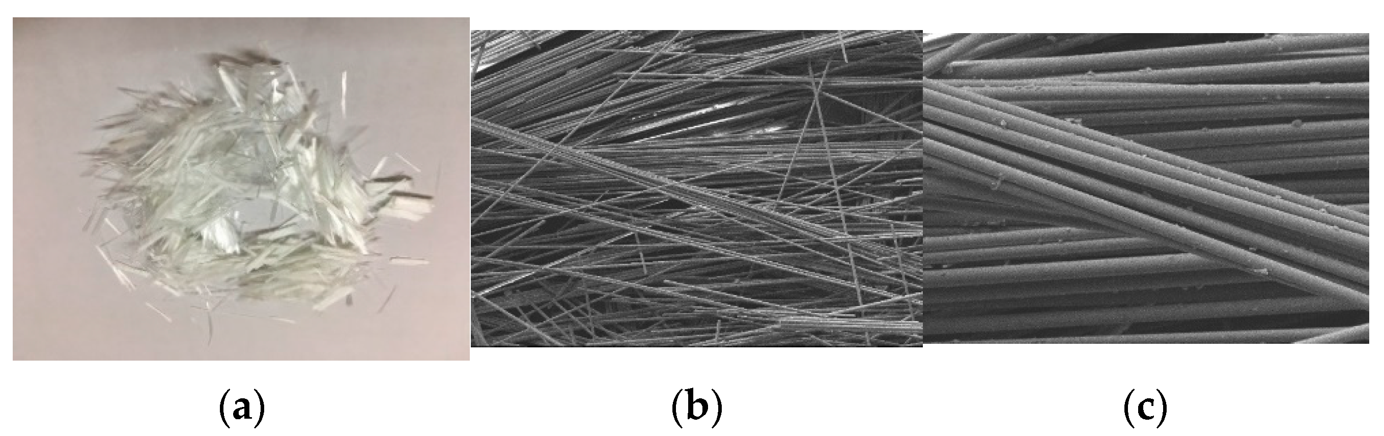
The KD-BEP epoxy asphalt used in this trial was a mixture Japan epoxy resin (Aichi County Jindai Chemical Co., Ltd., Tokyo, Japan) and A-70 petroleum-based asphalt (Guangdong Foshan Shell Co., Ltd., Foshan, China). The Japan epoxy resin components included main agent (A, untreated epoxy resin) and curing agent (B), and they were mixed at a 56:44 ratio, and the ratio of the resin to A-70 base pitch was 50:50 [31]. Performance parameters of the epoxy resin A and B after mixing and curing are shown in Table 1. The performance parameters of the base asphalt and epoxy asphalt are shown in Table 2.
The epoxy asphalt mixture was designed by the Marshall test method (JTG E20—2011, JTG F40—2004). The gradation of the epoxy asphalt mixture determined by the test is shown in Table 3. Fiberglass asphalt mixtures with different amounts and lengths of fibers were designed using the same gradation, and the Marshall test was conducted to determine the optimal bitumen/aggregate ratio (the ratio of the binder mass to the dry aggregate mass), controlling the air voids at the same level of about 1.5%.

2.2. Fiberglass

The fiberglass used in the sample was E-type fiberglass [32] and was 3 mm, 6 mm, 9 mm and 12 mm in length. The technical indicators are shown in Table 4. The appearance of the fiberglass is shown in Figure 1a, and the microscopic image of the fiberglass obtained using scanning electron microscopy is shown in Figure 1b,c. The fiberglass surface is smooth without texture and distributed in bundles.

2.3. Related Tests of Fiberglass-Modified Epoxy Asphalt Mastic

2.3.1. Preparation of Epoxy Asphalt Mastic Specimens
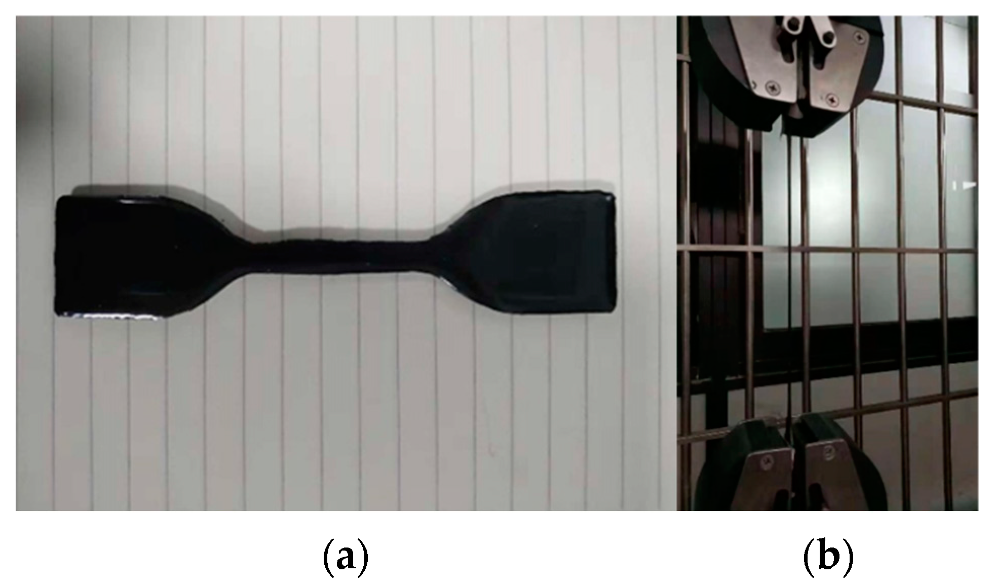
Asphalt mastic is a dispersion system composed of dispersants in asphalt. It is the initial dispersion system for asphalt mixtures. The structure, composition and properties of asphalt concrete are directly related to its the performance, so it is necessary to study the influence of fiberglass on the performance of asphalt mastic.
The mastics with fiberglass accounting for 1%, 2% and 3% of the epoxy asphalt mass were trial-mixed. As the fiberglass was 9 mm and 12 mm long, it was difficult to disperse the fiberglass in epoxy asphalt at 2% and 3%. The fiberglass of 9 mm and 12 mm were mixed with mastic at a dosage of 1%.
First, the base asphalt was preheated in an oven at 160 °C. The main epoxy resin and curing agent were incubated in an oven at 60 °C, and the filling was incubated at 180 °C for at least 4 h. The base asphalt was weighed. It was placed in a beaker. It was placed in an oil bath at 160 °C, and it was stirred with a high-speed shearing machine. The main epoxy agent and curing agent were added to the beaker at a mass ratio of 56:44. They were blitzed with a glass rod for 3 min. The resin and matrix asphalt at a mass ratio of 1:1 were blitzed with a high-speed shearer for 3 min, and then the filler was added to the epoxy asphalt and blitzed until they were evenly combined, at about 150 r/min. The mastic was poured into a mold to form a test piece. This was placed in the oven for 30 min at 160 °C and then for four days at 60 °C to test the performance of the mastic.

2.3.2. Tensile Test

The strength and deformation ability of epoxy asphalt mastic were tested using tensile test (ASTM D638). The test temperature was 23 °C, and the loading rate was 500 mm/min. The test was conducted using a universal material testing machine, and the tensile strength and elongation at break of the epoxy asphalt mastic were calculated. Photos of the experiment are shown in Figure 2.

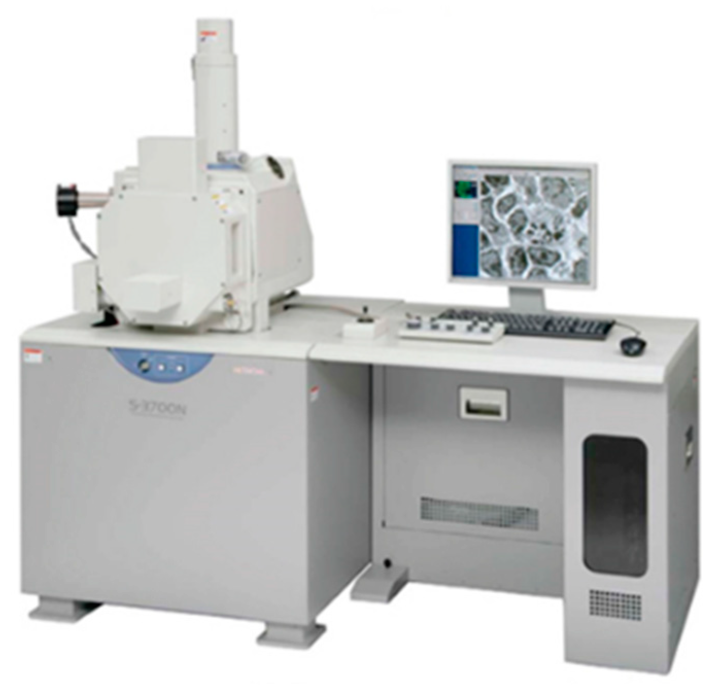
2.3.3. SEM Scanning Test

In order to study the bonding effect of the fiberglass and epoxy asphalt, the surface of the fiberglass-modified epoxy asphalt mastic was observed using SEM to examine the tensile fracture performance. The surface state of the extracted fiberglass and the binding of the root system to the epoxy asphalt were observed. The strength of the epoxy asphalt material depends on the 3-D network structure of the epoxy resin [20], so the bonding of the filler to the 3-D mesh structure of the epoxy resin can be observed by immersing the same tensile fracture surface samples in trichloroethylene for at least 12 h and dissolving the epoxy asphalt on the fracture surface of the sample, thus facilitating the observation of the bonding of the epoxy resin matrix to the fiberglass.

2.4. Relevant Tests of Fiberglass-Modified Epoxy Asphalt Mixture

2.4.1. Marshall Test

The optimal dose of fiberglass was determined using the Marshall test. The optimal bitumen/aggregate ratio was determined for the optimal dose of fiberglass epoxy asphalt mixture, and the effect of the fiberglass length on the performance of the epoxy asphalt mixture was further studied.

2.4.2. Bending Test

The low-temperature properties of the epoxy asphalt mixture were evaluated by bending test. The three-point bending test was carried out on 250 mm × 30 mm × 35 mm asphalt mixture trabecular specimens. The test temperatures were 15 °C and −10 °C. Furthermore, 15 °C was the conventional test temperature required by the specification, and the −10 °C was the temperature set to evaluate the low-temperature performance of the mixture. The loading rate was 50 mm/min, and the trabecular span was 200 mm. The peak load and maximum mid-span deflection of the specimen were recorded and used to calculate the ultimate flexural tensile strength, ultimate flexural tensile strain and ultimate flexural stiffness modulus of the specimen.

2.4.3. Four-Point Bending Fatigue Test

The effect of fiberglass on the fatigue property of the epoxy asphalt mixture was studied using a four-point bending fatigue test. The four-point bending fatigue test was carried out on a 380 mm × 63.5 mm × 50 mm composite beam. The test temperature was 15 °C, the loading waveform was partial sine wave, the loading frequency was 10 Hz, and the loading method was strain control. Considering the impact and overload of the vehicle and the efficiency of the fatigue test, strain levels of 800 με and 1000 με were used in the test.

2.4.4. SEM Scanning Test

Using a scanning electron microscope (SEM), the bonding of the fiberglass and epoxy asphalt in the fiberglass-modified epoxy asphalt mixture, the effect of fiberglass reinforcement on crack resistance performance, the restraint effect on microcrack expansion and the distribution of the fiberglass in the epoxy asphalt mixture were analyzed. Image acquisition was performed using an S-3700 scanning electron microscope (shown in Figure 3).
Based on the above tests, the research process of this paper is shown in Figure 4.

3. Results and Discussion

3.1. Properties of Fiberglass-Modified Epoxy Asphalt Mastic
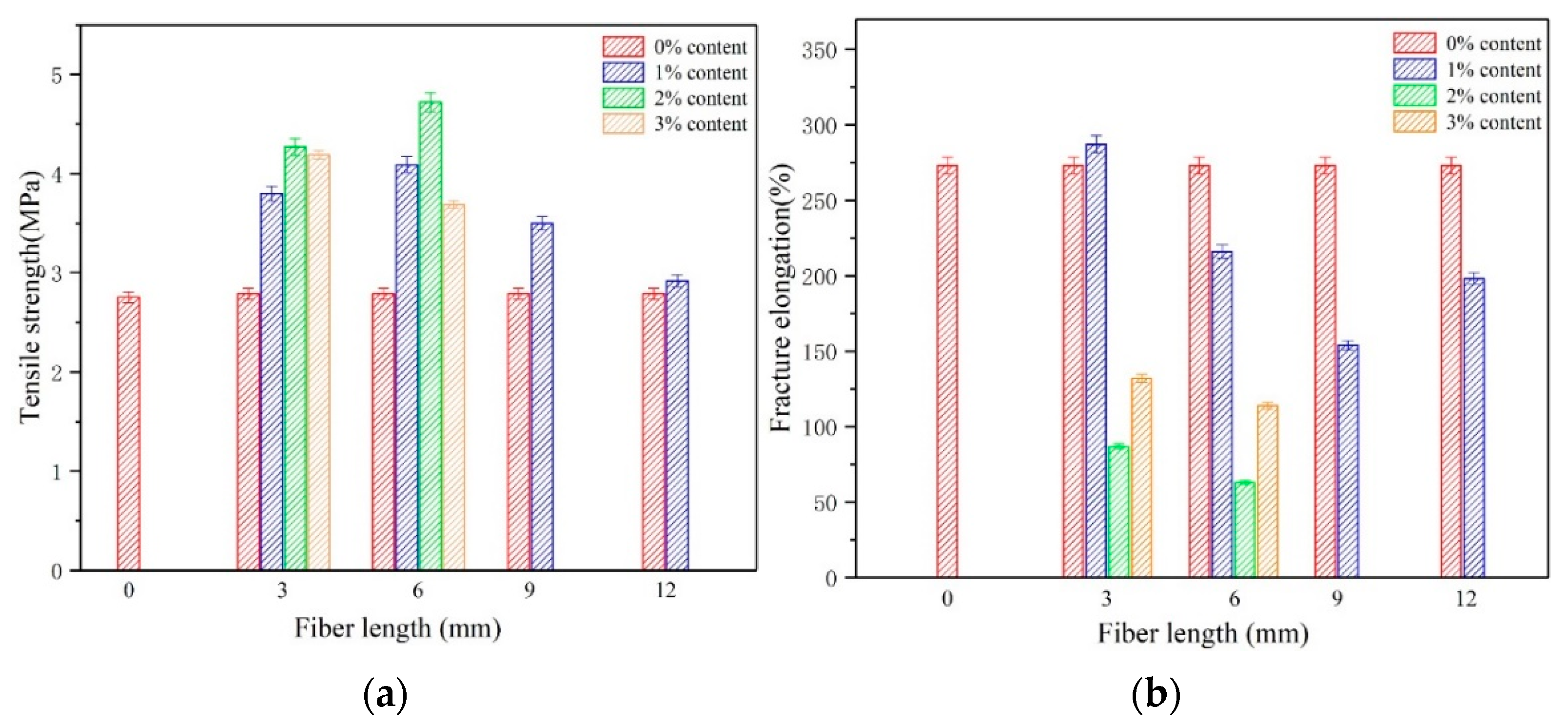
3.1.1. Tensile Test

The effects of the quantity and length of the fiberglass on the mixing and dispersion of the fiberglass can be indirectly assessed using a tensile test. The tensile test scheme and data analysis are shown in Figure 5. The results reveal that the tensile strength of the epoxy asphalt mastic can be significantly increased by adding fiberglass:
(1)
The enhancement effect of fiberglass on epoxy asphalt mastic varies with the doping amount of the same fiberglass length. According to the tensile test results following the doping of different amounts of 3 mm and 6 mm fiberglass, the effect was most obvious when 2% was added, and the tensile strength increased by 53.0% and 69.2%, respectively, compared with the control group.
(2)
When the fiberglass content remained the same and the length of the fiberglass varied, the reinforcement effect on the epoxy asphalt mastic varied. At a 1% dose, the effect of modification was best at 6 mm length, and the strength was 46.6% higher than that of the control group. Therefore, the length and content of fiberglass plays an important role in the tensile strength of epoxy asphalt mastic.

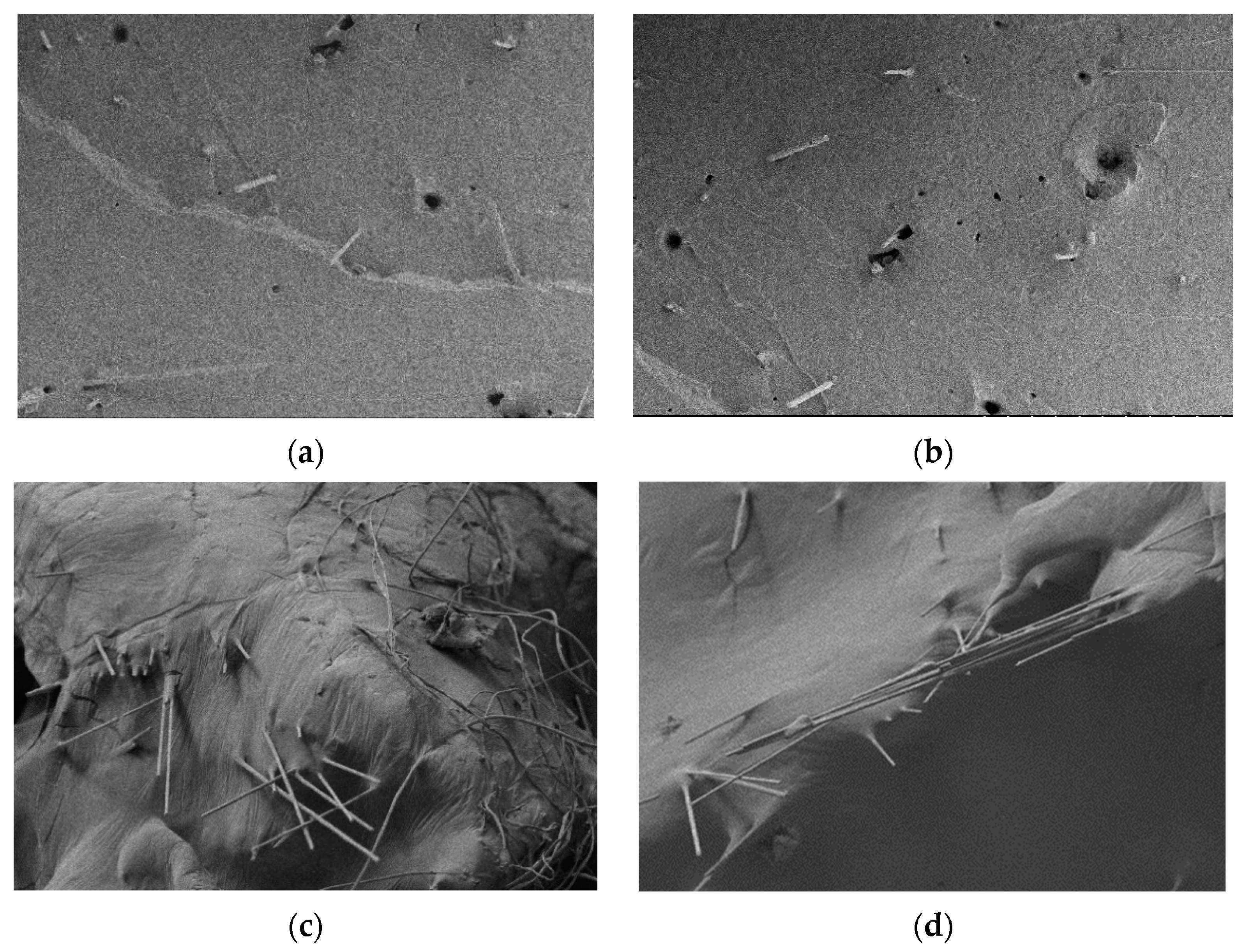
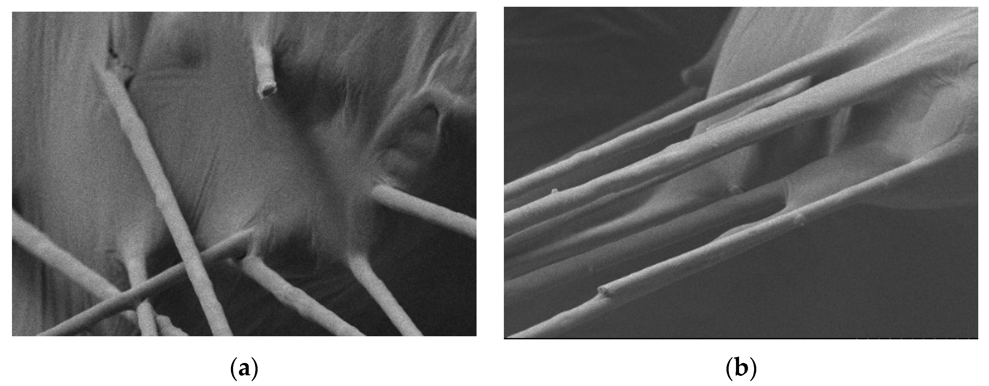
3.1.2. Microscopic Analysis of the Fracture Surface of the Mastic Tensile Specimen

The distribution of fiberglass with different lengths and 1% content on the fracture surface is shown in Figure 6. The results confirm that the tensile cross-sections of the 3 mm and 6 mm fiberglass epoxy asphalt were relatively flat, and the fiberglass distributed on the cross-sections was single filaments. The results demonstrate that the two lengths of fiberglass had better mixing effects and were relatively uniform in the epoxy asphalt matrix. However, the length of the exposed fiberglass was shorter due to the limitation of the length of the fiberglass, indicating that the anchorage distance of the fiberglass was also shorter under stress. Fiberglass of lengths 9 mm and 12 mm were added to the epoxy asphalt to determine the role of the convex and concave forms of the fiberglass in the tensile strength. The fiberglass showed the phenomenon of agglomeration and bunching which reduces the contact area of the fiberglass and epoxy asphalt, resulting in local defects in the tensile specimen; the strength of the specimen was reduced, but for both lengths of fiber, the effect of the distance was relatively strong.
The bonding of the fiberglass and epoxy asphalt is shown in Figure 7. The exposed part of the fiberglass was wrapped in epoxy asphalt, and the root of the fiberglass showed good association with the epoxy asphalt at the fracture surface. The fiberglass itself was well-infiltrated with the epoxy asphalt, which means that there was good bonding between the fiberglass and the epoxy asphalt matrix. Based on the bonding effect, fiberglass can be used as the reinforcing material for epoxy asphalt.
The strength of the epoxy asphalt material was determined by the three-dimensional network structure of the epoxy resin. Therefore, the bonding effect of the fiberglass and the epoxy resin on the three-dimensional network structure can be observed using experiments. The epoxy resin structure was exposed by etching some samples. The electron microscope scanning results are shown in Figure 8. The picture reveals that the fracture surface of the specimen was basically the same as that of the unetched specimen. The fracture surface of the specimen with the shorter fiberglass was similar. The fracture surface was relatively flat, as shown in Figure 8a; however, if the added fiberglass was longer, the fracture surface was irregular, as shown in Figure 8b. The uniformly distributed fiberglass can achieve a better bonding effect with the epoxy resin structure and still bond well with the epoxy resin matrix at the fracture, without obvious defects at the roots; see Figure 8c. The fiberglass showed a slight agglomeration phenomenon and had obvious defects on the fracture surface, which had a great influence on the reinforcement effect of the fiberglass, as shown in Figure 8d. Figure 8e,f show two parts of a fiberglass bundle on a fractured surface. Figure 8e shows that the specimen was damaged along the fiber bundle direction because the contact area between the fiber bundling and the substrate was greatly reduced, resulting in a weaker bonding effect, and the distribution of all the fibers were in a certain direction rather than in a random three-dimensional distribution, making the stress concentration in the fiber bundle confer susceptibility to damage. As shown in Figure 8f, the fiberglass did not bind well to the epoxy resin at the root of the fracture.

3.2. Properties of Fiberglass-Modified Epoxy Asphalt Mixture

3.2.1. Determination of the Content of Glass Fiber

The content of the glass fiber in the mixture was determined using a Marshall test. Due to the different states of the mixing process between the mixture and the asphalt mastic, the influence of the proportion of the participating fibers was further evaluated. The mass ratio of fiber to mastic used in the experiment was 2%, 5% and 10%. The three ratios represent the optimum glass fiber content, the moderate content and the excess content determined by the mastic test.
In the mixing process, it was found that the 3 mm and 6 mm glass fibers can be uniformly distributed in the mixture as monofilaments, while some of the 9 mm and 12 mm glass fibers would form clumps under the drive of the leaves, some of them were distributed in the mixture, and some were stuck on the leaves of the mixing pot. The clumping phenomenon of the 12 mm glass fibers was especially serious. Some of the glass fibers were distributed on the surface of the Marshall specimen during the forming process. The mixture specimens with a uniform and bundle distribution of glass fibers are shown in the Figure 9.
The results of the Marshall stability test are shown in Table 5. The addition of glass fiber can significantly improve the performance of the Marshall specimens of the epoxy asphalt mixture, but the air voids increased if the bitumen/aggregate ratio was not increased.
The experimental results show that the stability of each length of glass fiber reached the maximum when the fiber dosage was 5%. Compared with the control group, the Marshall stability of the mixture with the length of 3 mm, 6 mm, 9 mm and 12 mm glass fibers increased by 19.9%, 32.8%, 40.1% and 31.1%. It indicated that 9 mm glass fibers had the best strengthening effect, and the air voids increased with the increase in fiber dosage.
According to the test results, the 6 mm and 9 mm glass fibers were preliminarily determined. The stability of each length of glass fiber reached the maximum when the fiber dosage was 5%, so the 5% glass fiber dosage was used in the subsequent test of the epoxy asphalt mixture. At the same time, due to the insignificant strengthening effect of the 3 mm glass fiber, only 6 mm, 9 mm and 12 mm glass fibers were tested in the subsequent study of the epoxy asphalt mixture.

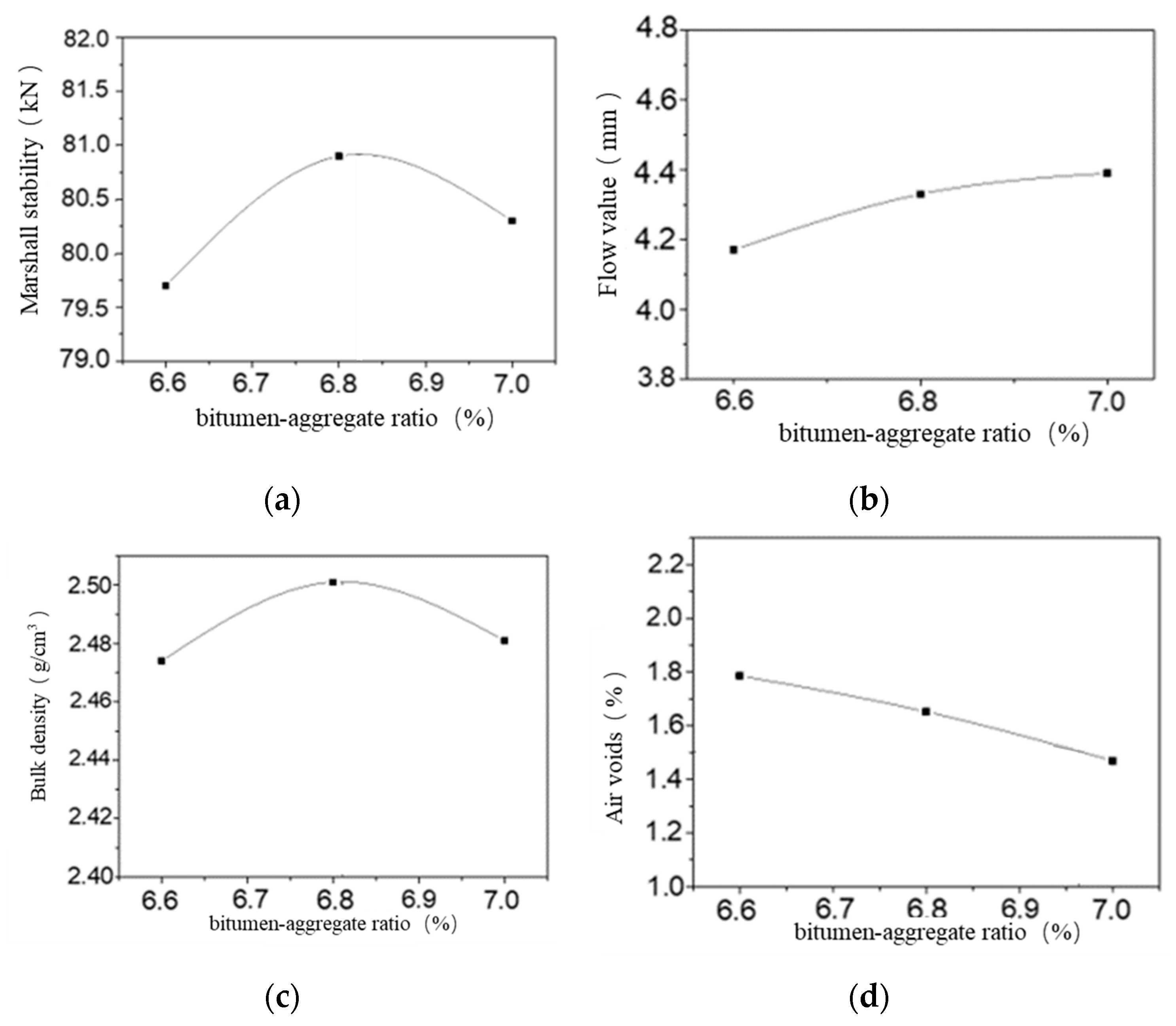
3.2.2. Determination of Optimum Bitumen/Aggregate Ratio

The Marshall test was carried out on the epoxy asphalt mixture with 6 mm, 9 mm and 12 mm glass fibers at a 5% fiber–mastic mass ratio, and the results are shown in Table 6. The initial test showed that the bitumen/aggregate ratio was 6.6%, 6.8% and 7.0%. The optimum asphalt ratio of the epoxy asphalt mixture with each length of glass fiber was determined.
The Marshall test results of the epoxy asphalt mixtures mixed with 6 mm glass fiber were taken as an example. Taking the bitumen/aggregate ratio as the abscissa, the relation diagram between the bitumen/aggregate ratio and the Marshall test result data was drawn, as shown in Figure 10. The range of the bitumen/aggregate ratio meeting the specification requirements was determined through the relation diagram, so that the air voids of the mixture were determined to be 1.5%.
According to the figure, the maximum bulk density corresponded to the bitumen/aggregate ratio of 6.82%, the maximum stability corresponded to the bitumen/aggregate ratio of 6.86%, and the air void ratio corresponded to the bitumen/aggregate ratio of 6.97%. Taking their average value, the optimum bitumen/aggregate ratio corresponding to the 6 mm glass fiber was 6.88%. The optimum bitumen/aggregate ratio corresponding to the 9 mm and 12 mm glass fibers was calculated using the same method.
Table 7 shows the optimal admixture of the different lengths of fiberglass in the epoxy asphalt mixtures and the optimal bitumen/aggregate ratio determined by the Marshall test.

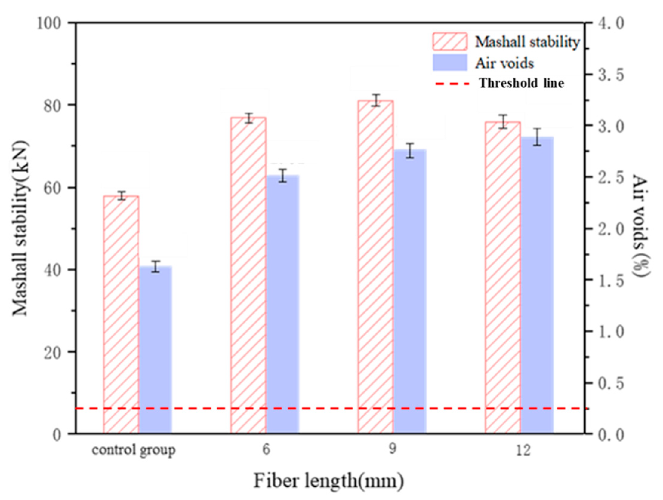
3.2.3. Marshall Stability Test

The Marshall test results for the epoxy asphalt mixture, corresponding to the optimum bitumen/aggregate ratio when the fiberglass content was 5%, are shown in Figure 11. The test results show that the stability of the epoxy asphalt mixture with 6 mm fiberglass increased by 39.7% compared with the control group (without fiberglass), and the stability of the epoxy asphalt mixture with 9 mm fiberglass increased by 43.5% compared with the control group. The results show that the strength of the epoxy asphalt mixture was significantly enhanced by the fiberglass.

3.2.4. Bending Property Test of Mixture
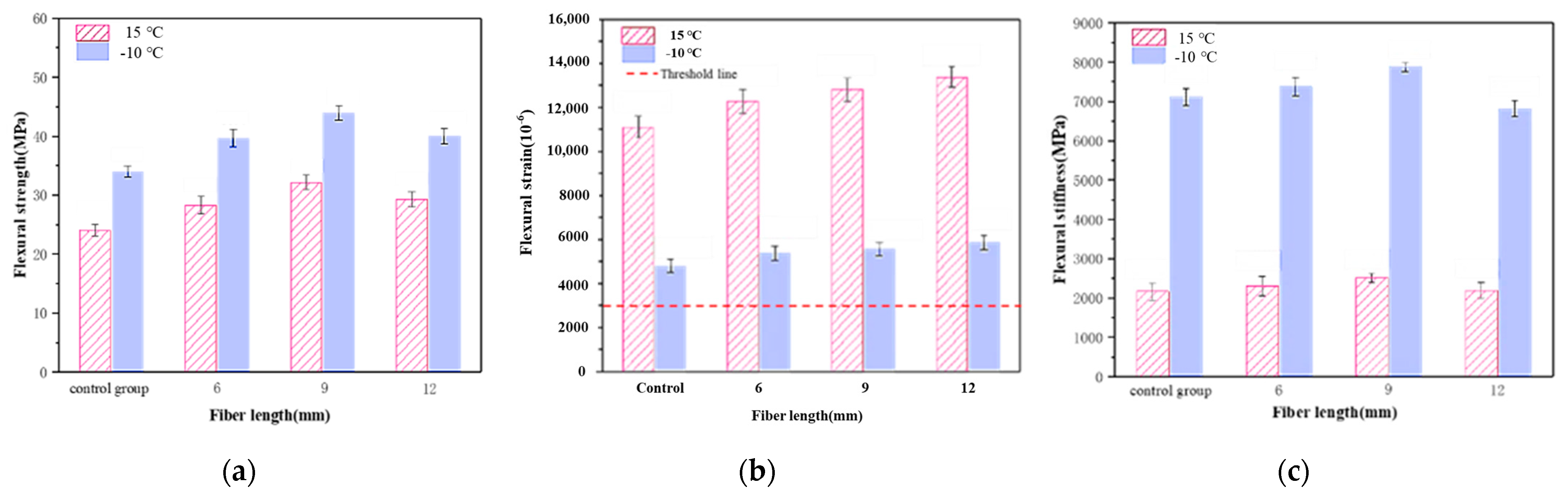
The test data for the bending tensile strength, ultimate bending tensile strength and bending stiffness modulus of epoxy asphalt mixture trabeculae with the different lengths of fiberglass are shown in Figure 12. The test results shown are as follows:
(1)
Under the test temperature of 15 °C, the bending tensile strength of the epoxy asphalt mixtures with 6 mm, 9 mm and 12 mm fiberglass was 17.6%, 33.7% and 21.7% higher, respectively, than that in the control group, i.e., the epoxy asphalt mixture with the 9 mm fiberglass had the highest bending tensile strength. The ultimate bending tensile strain was 10.6%, 15.3% and 20.4% higher, respectively, than that in the control group. The epoxy asphalt mixture with the 12 mm fiberglass had the highest ultimate bending tensile strain and the best low-temperature flexibility. The bending strength modulus was 6.4%, 16.0% and 1.1% higher, respectively, than that in the control group, and the bending strength modulus of the epoxy asphalt mixture with the 9 mm fiberglass was the highest.
(2)
The bending and tensile strengths of the epoxy asphalt mixtures with 6 mm, 9 mm and 12 mm fiberglass were 16.8%, 29.25% and 17.7% higher, respectively, than that of the control group at −10 °C. Compared with those in the control group, the final bending and tensile strain were 12.6%, 16.7% and 22.8% higher, respectively, and the bending stiffness modulus of the epoxy asphalt mixture was 3.7% and 10.7% higher, respectively, than that of the 6 mm and 9 mm fiberglass mixtures. The bending stiffness of the 12 mm fiberglass mixture was 4.1% lower than that of the control group.
(3)
The bending test results show that fiberglass can obviously improve the bending performance of epoxy asphalt mixtures. The laws of the influences of the fiberglass length on the bending tensile strength and ultimate bending tensile strain were basically the same; that is, the bending tensile strength of the epoxy asphalt mixture with the 9 mm fiberglass was the highest, and the ultimate bending tensile strain increased with an increase in the length of the fibers. The range of the intensity and strain index was similar under different temperature conditions. At 15 °C, the improvements in the bending and flexural tensile strengths of the mixture were slightly higher than those at −10 °C, but the improvement in the ultimate flexural tensile strain was slightly lower than that at −10 °C. Compared with the mixing dispersibility of the fibers, the effective length of the fibers has a great influence on the ultimate bending and tensile strain of the epoxy asphalt mixture.

3.2.5. Mixture Fatigue Property Test

The fatigue property test results for the epoxy asphalt mixture are shown in Figure 13. The variation trends for the bending stiffness modulus of the mixture under two strain conditions are shown in Figure 14. The results shown are as follows:
(1)
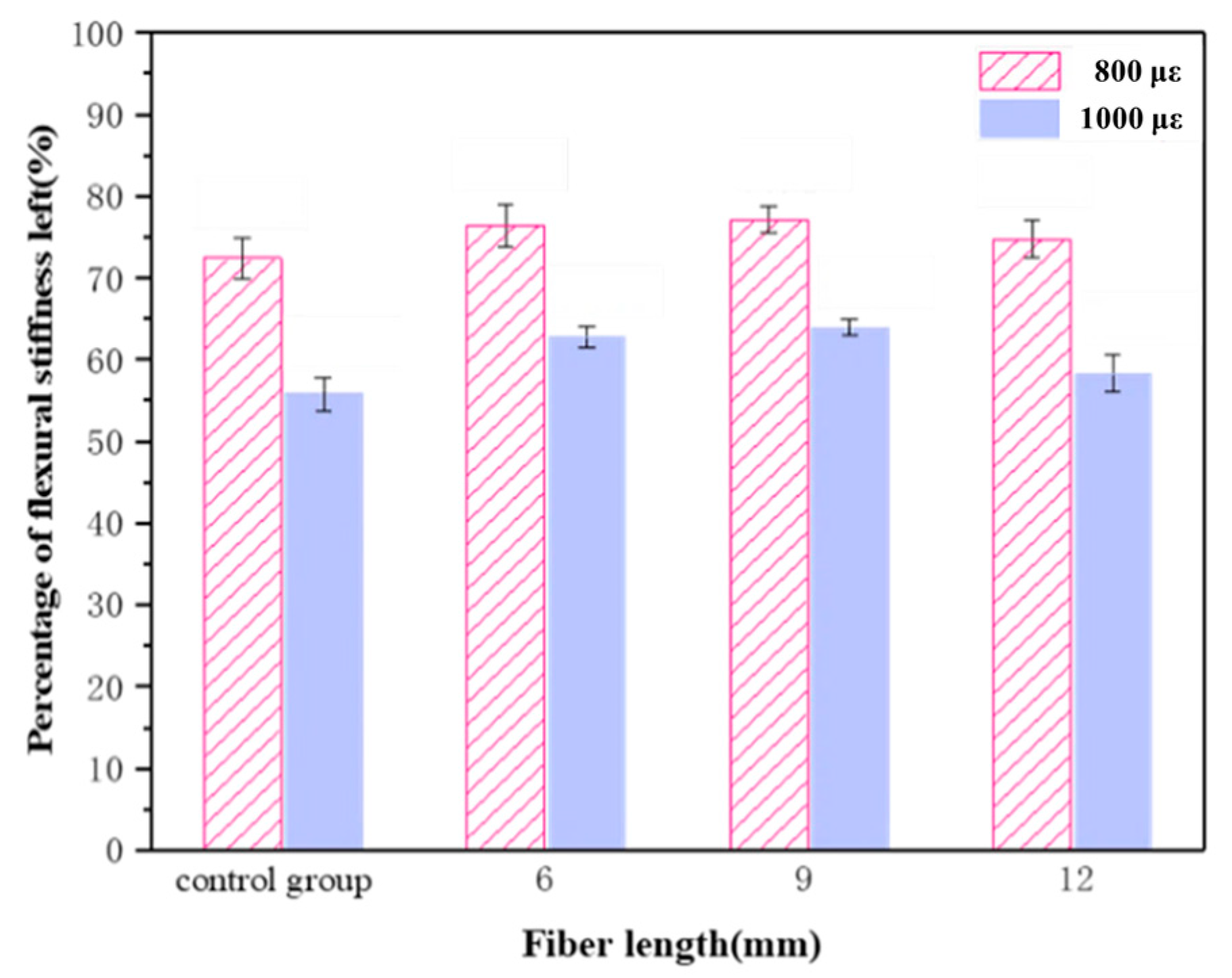
The fatigue life of the control group and the experimental group for the three lengths of fiberglass exceeded 1 million times at both 800 μm and 1000 μm strain levels, and their fatigue properties were evaluated by comparing the flexural stiffness modulus residue ratio at 1 million times the load of each group, considering the conditions at the time of the tests.
(2)
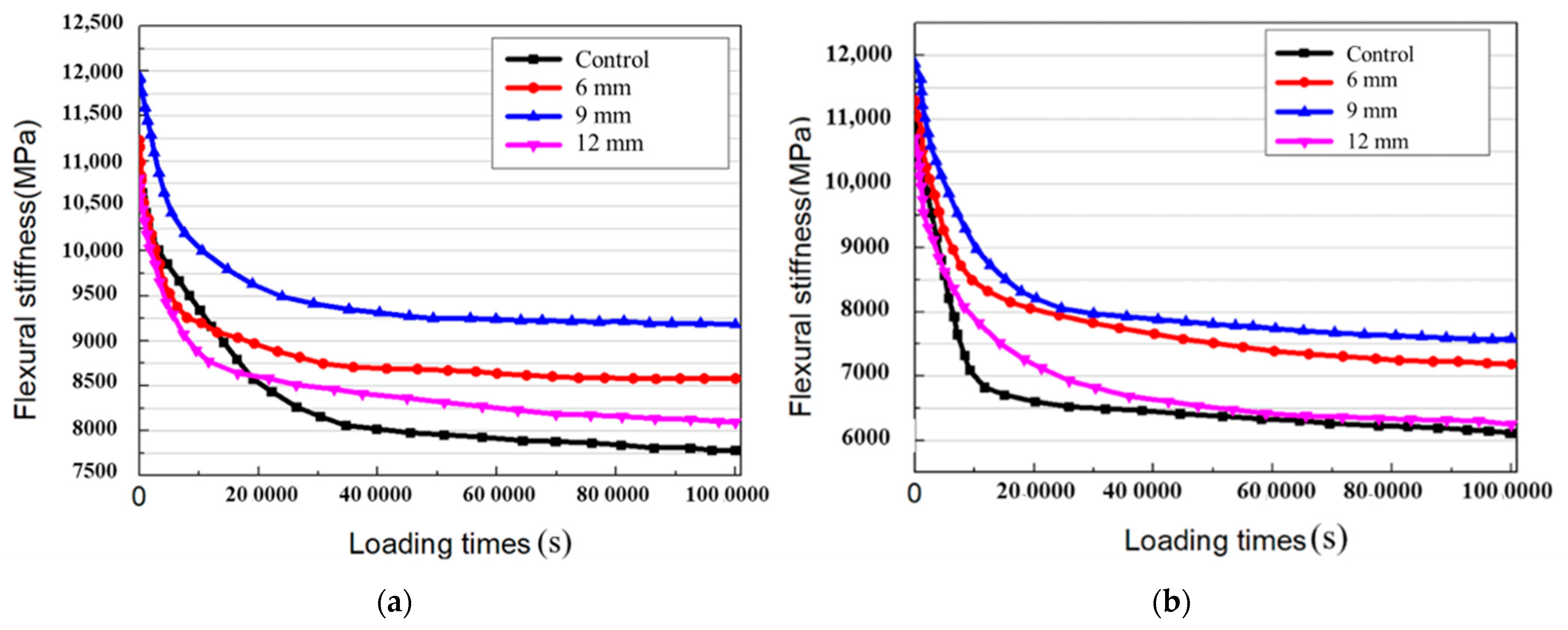
When the strain level was 800 με, the addition of fiberglass can significantly improve the fatigue property of the epoxy asphalt mixture, and the fatigue property of the epoxy asphalt mixture with the 9 mm fiberglass showed the most obvious improvement. However, the performance improvement for the 6 mm fiberglass mixture was not very different, and the performance improvement for the 12 mm fiberglass mixture was smaller. The stiffness modulus of the 9 mm fiberglass mixture remained high during the experiment, while the poor dispersibility of the 12 mm fiberglass increased the porosity of the mixture, resulting in less performance improvement.
(3)
When the strain level was 1000 με, the fatigue property improvement effect of adding fiberglass to the epoxy asphalt mixture was higher than that at the 800 με strain level test, and the best fatigue property improvement effect was achieved by adding fiberglass with a length of 9 mm. The addition of fiberglass changed the change trend for the modulus decay of the mixture, which tended to be moderate at the time of loading up to 100,000 times.

3.2.6. Statistical Analysis of Fatigue Property Test Data

The analysis of variance (ANOVA)–Tukey’s HSD (honestly significant difference) analysis was performed to check the statistical significance of the variation in the fatigue property test data [33,34].
In the process of data analysis, glass fiber was used as the qualitative index, and the residual modulus ratio was used as the qualitative index to study whether there was a significant difference in the fatigue performance after adding glass fiber. The results of the ANOVA at strain level of 800 με are shown in Table 8. Data analysis shows that different fiberglass samples had significant residual modulus ratios (p < 0.05), indicating that different fiberglass samples had different residual modulus ratios. The results of the post hoc tests (multiple comparisons) obtained by Tukey’s method are shown in Table 9. Data analysis results show that fiberglass had a significant 0.01 level in the residual modulus ratio (F = 22.349, p = 0.000), and the comparative results of the mean scores of the groups with significant differences were “9 mm > 12 mm; 12 mm > control group; 6 mm > control group; 9 mm > control group”.
The results of the ANOVA at a strain level of 1000 με are shown in Table 10. The data analysis shows that different fiberglass samples had significant residual modulus ratios (p < 0.05), indicating that different fiberglass samples had different residual modulus ratios. The results of the post hoc tests (multiple comparisons) obtained by Tukey’s method are shown in Table 11. The data analysis results show that fiberglass had a significant 0.01 level in the residual modulus ratio (F = 23.007, p = 0.000), and the comparative results of the mean scores of the groups with significant differences were “6 mm > 12 mm; 9 mm > 12 mm; 6 mm > Control group; 9 mm > Control group”.
According to the results of the HSD analysis, adding glass fiber can significantly improve the fatigue performance. The 9 mm glass fiber had the most marked effect on the fatigue performance of the mixture.

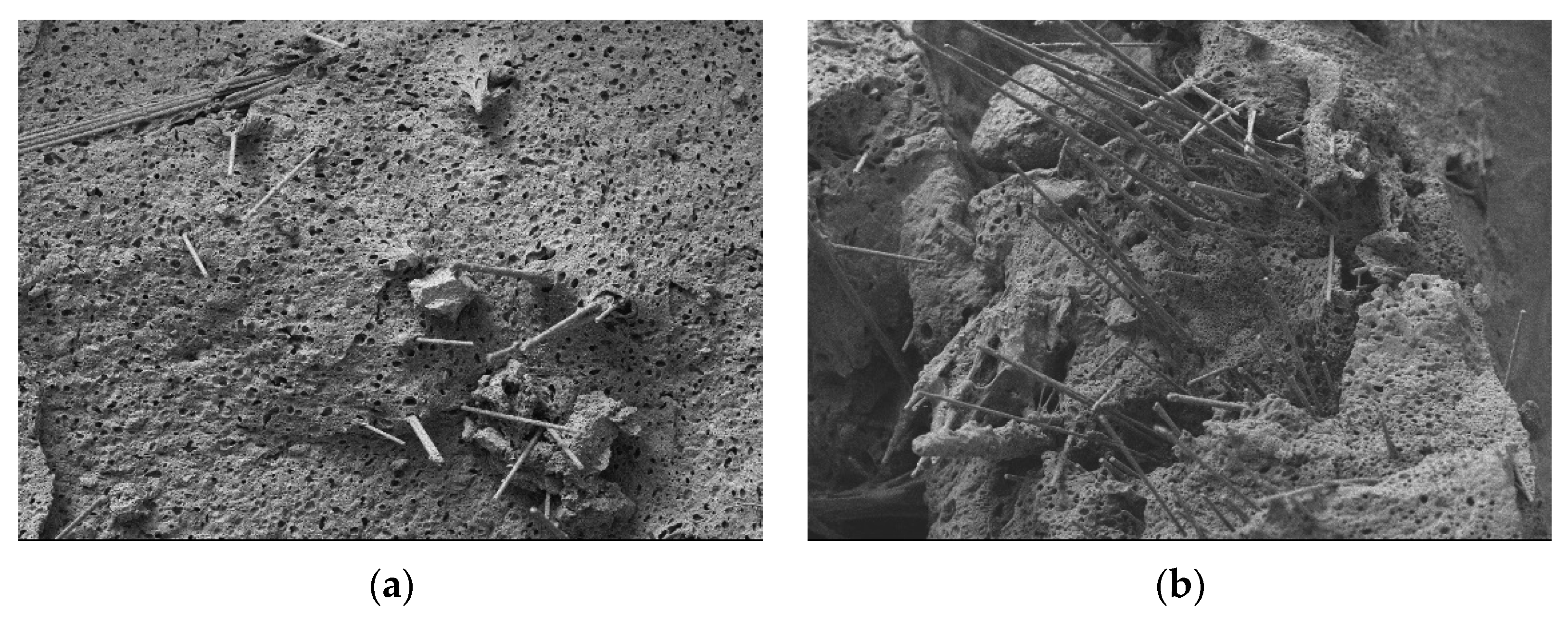
3.2.7. Mixture Cross-Sectional Microscopic Analysis
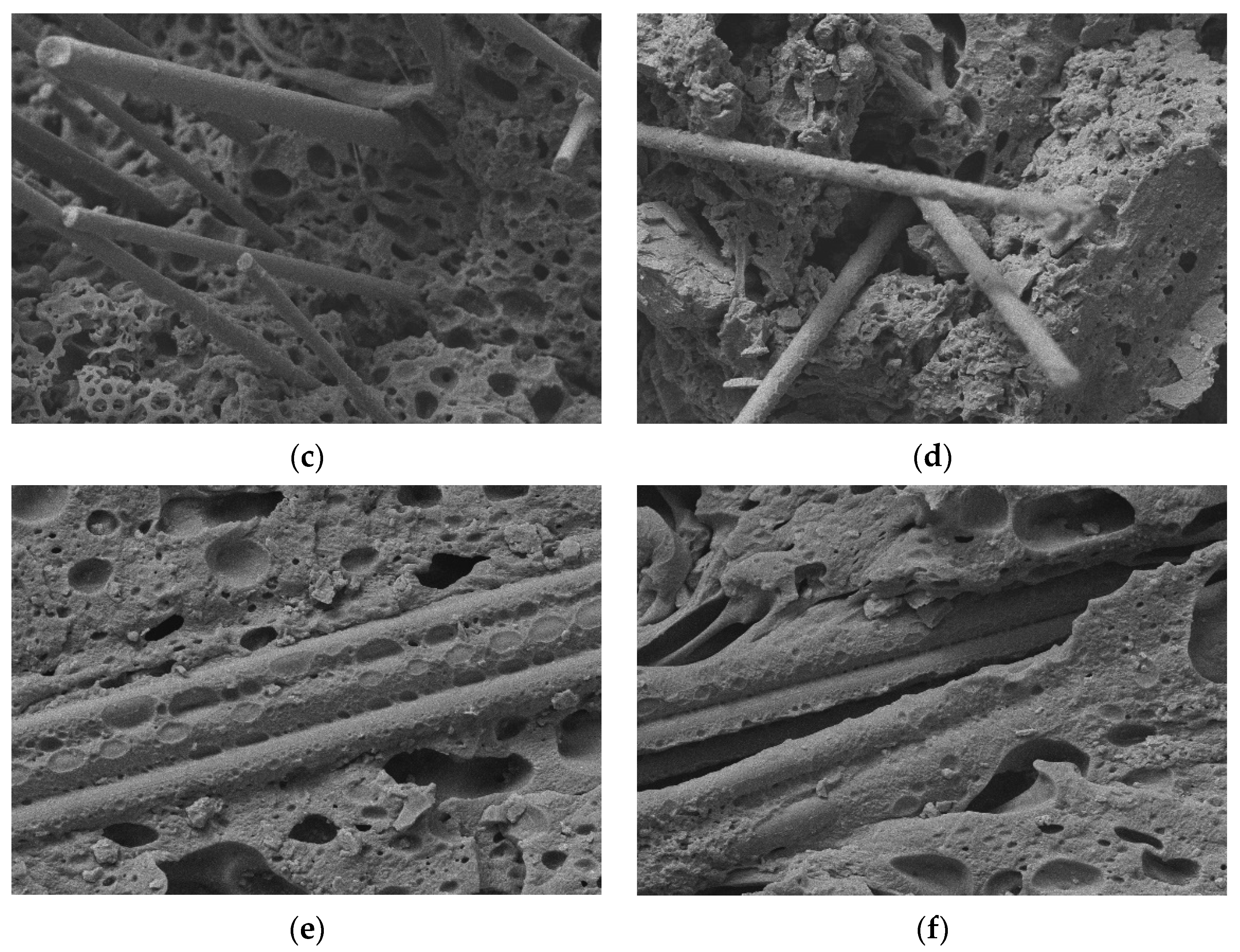
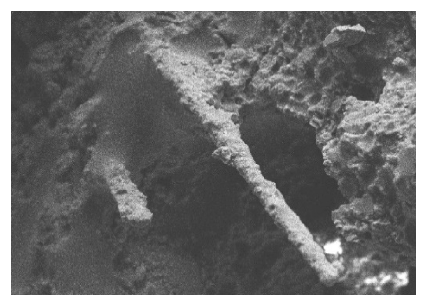
SEM was used to collect images of the fiberglass and epoxy asphalt mastic combination at the fracture surface, observe the surface state of the fiberglass at the fracture surface, examine the combination of the root and epoxy asphalt mixture and analyze the strength formation mechanism of the fiberglass and epoxy asphalt mixture and the effect of reinforcement and crack resistance. The ratio of the fiberglass to epoxy asphalt mixture before etching is shown in Figure 15, and the ratio of the fiberglass to epoxy resin after etching is shown in Figure 16. The results shown are as follows:
(1)
Before etching, the fiberglass surface on the fractured surface of the mixture was coated with epoxy asphalt, indicating that the fiberglass epoxy asphalt had a good bonding effect.
(2)
After etching, the asphalt on the surface of the specimen had dissolved away, the epoxy resin skeleton structure was exposed, the fiberglass surface was wrapped in epoxy resin and staggered in space, the fiberglass spanned both sides of the microcrack, and more agglomerates and clusters of the 12 mm fiberglass appeared.
(3)
The SEM images demonstrated that the fiberglass and epoxy asphalt mixture had good deformation coordination abilities and remarkable crack resistance effects. Fiberglass, as a reinforcing material in the epoxy asphalt mixture matrix, can effectively inhibit the development of microcracks and reduce stress concentration. The enhancement effect of fiberglass on an epoxy asphalt mixture depends on the dispersibility and effective length of the fiberglass. There was slight agglomeration and clustering in the epoxy asphalt mixture with the 9 mm fiberglass. This effective length of the fiberglass still allowed for good performance improvements, but there was too much aggregation and condensation in the mixture with the 12 mm fiberglass. As a result, the fiberglass and matrix material did not combine well, leading to an increase in the weak links in the mixture and a decrease in its properties.

4. Conclusions

In order to evaluate the fatigue resistance and durability of an epoxy asphalt mixture with fiberglass, a systematic experimental study was carried out. The effects of the fiberglass dosage and length on the mechanical properties of the epoxy asphalt mastic and epoxy asphalt mixture were discussed, and the mechanism of the effect by which fiberglass enhances of the performance of the epoxy asphalt mixture was studied in combination with microscopic observations of the fracture surface of the epoxy asphalt mastic and the fracture surface of the mixture. The main conclusions are as follows:
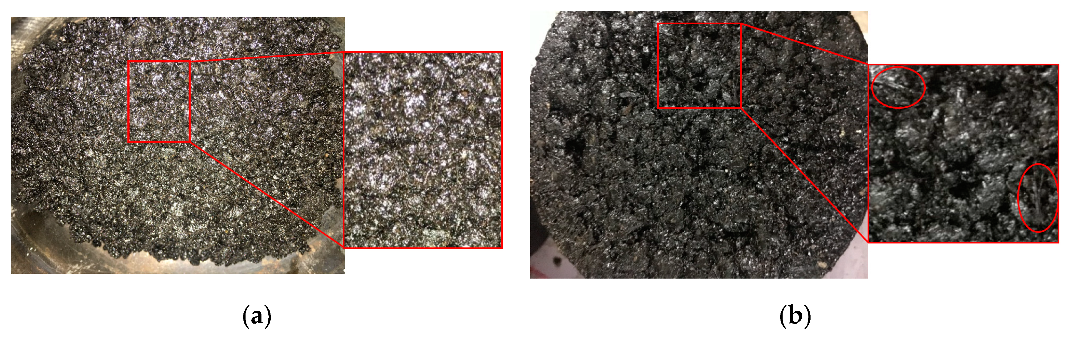
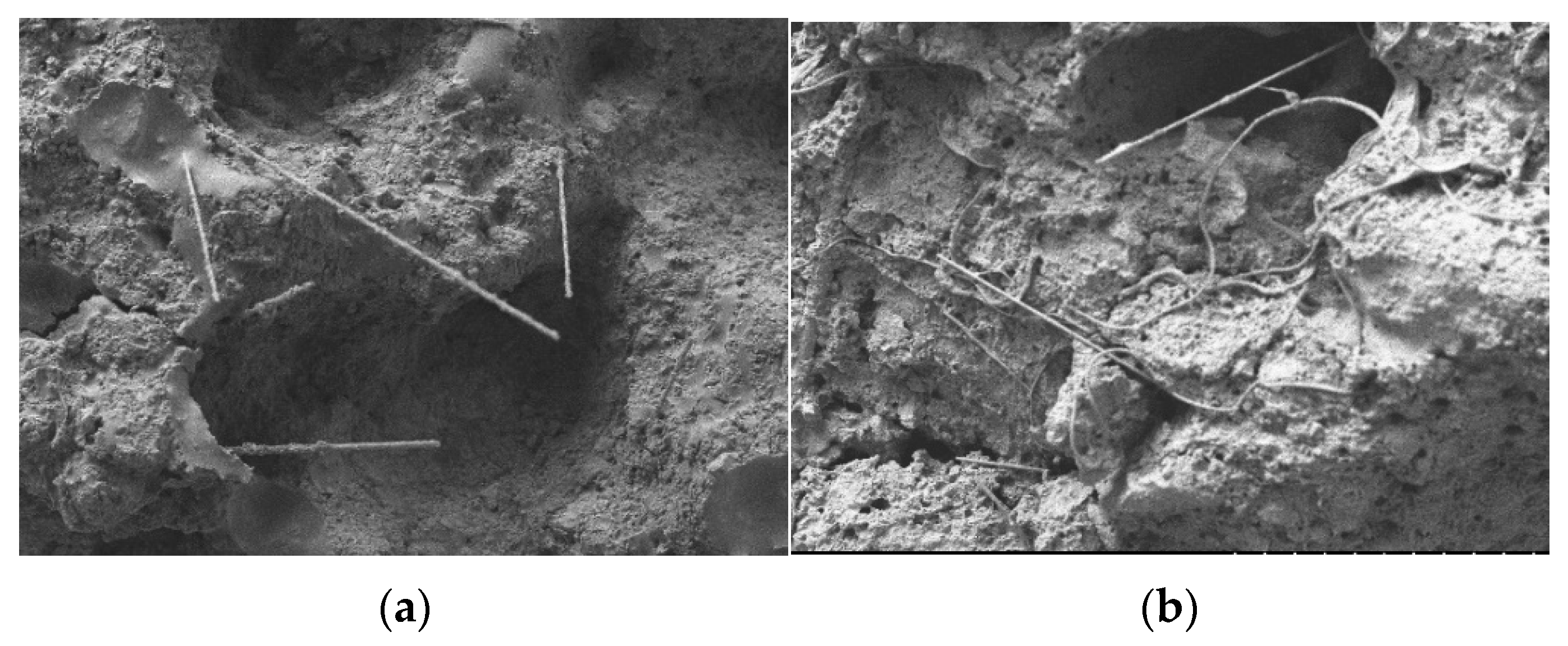
  • The tensile test of the asphalt mastic showed that the tensile strength of an epoxy asphalt mastic can be significantly increased by fiberglass. Compared with the epoxy asphalt mastic without fiberglass, the tensile strength of the fiberglass epoxy asphalt mastic with a length of 6 mm and a content of 2% increased by 69.2%. It was necessary to optimize the amount of fiber added.
  • The SEM scanning observation of the tensile section of the epoxy asphalt mastic demonstrated that the fiberglass with high strength was distributed uniformly and randomly in space. However, there were more fiber agglomeration and bundles at the fracture of the specimen with a lower strength. The mixing of the fiberglass, due to excessive amounts or lengths, causes serious fiber agglomeration, and the reinforcement effect is not ideal.
  • The optimal amount of fiberglass in the epoxy asphalt mixture was 5%, and the optimal length was 9 mm. The addition of fiberglass can significantly improve the Marshall stability, flexural strength and fatigue resistance. The Marshall stability increased by 43.5%, and the flexural and tensile strengths increased by 33.7%. The strength and fatigue resistance of epoxy asphalt bridge deck pavement can be effectively improved by optimizing the design and adding fiberglass.
  • The dispersibility of fiberglass played an important role in its reinforcement effect. Evenly dispersed fiberglass can form a spatial network structure in the epoxy asphalt mixture, which can strengthen cracks and inhibit microcrack expansion. Unevenly dispersed agglomerated or bundled fibers may lead to local defects that are detrimental to the binding of fibers to matrix materials. The 9 mm fiberglass had both good dispersibility and a large length of action, with the most obvious enhancement effect.
  • The microscopic observation of the epoxy asphalt mixture confirmed that the evenly distributed fiberglass bound well to the epoxy resin matrix on the fracture surface and can prevent cracking during the tensile process. Compared with the fiberglass distributed as monofilaments, bundled or agglomerated fibers are mostly distributed along the fracture surface, which is inconsistent with the direction of the tensile force and not conducive to reinforcement.
  • In the future, we will explore more appropriate methods with which to study and evaluate the dispersion effect of glass fibers in epoxy asphalt mixtures and improve the analysis of the fiber-strengthening mechanism. Additionally, we will adopt a variety of gradation methods to study the fiber-strengthening effect and mechanism under different gradation conditions and to evaluate the performance-enhancing effects of different types, lengths and dosages of glass fibers.

Author Contributions

Conceptualization, X.M. and W.X.; Data curation, C.X.; Formal analysis, S.Y.; Funding acquisition, T.S.; Investigation, T.S.; Methodology, W.X. and X.H.; Project administration, Y.W.; Visualization, F.C.; Writing—original draft, J.W.; Writing—review & editing, J.W. All authors have read and agreed to the published version of the manuscript.

Funding

This research was funded by The National Key Research And Development Program Of China (“Inter-Governmental International Cooperation In Science, Technology And Innovation” Special Funds), grant number 2019YFE0117600 and the Zhejiang Scientific Research Institute of Transport Technology Innovation Program, grant number KY202100008. The APC was funded by the Zhejiang Scientific Research Institute of Transport.

Institutional Review Board Statement

Not applicable.

Informed Consent Statement

Not applicable.

Conflicts of Interest

The authors declare no conflict of interest.

References

  1. Apostolidis, P.; Liu, X.; Erkens, S.; Scarpas, A. Evaluation of Epoxy Modification in Bitumen. Constr. Build. Mater. 2019, 208, 361–368. [Google Scholar] [CrossRef]
  2. Xue, Y.; Qian, Z. Development and Performance Evaluation of Epoxy Asphalt Concrete Modified with Mineral Fiber. Constr. Build. Mater. 2016, 102, 378–383. [Google Scholar] [CrossRef]
  3. Qian, Z.; Liu, Y.; Liu, C.; Zheng, D. Design and Skid Resistance Evaluation of Skeleton-Dense Epoxy Asphalt Mixture for Steel Bridge Deck Pavement. Constr. Build. Mater. 2016, 114, 851–863. [Google Scholar] [CrossRef]
  4. Yin, H.; Zhang, Y.; Sun, Y.; Xu, W.; Yu, D.; Xie, H.; Cheng, R. Performance of Hot Mix Epoxy Asphalt Binder and Its Concrete. Mater. Struct. 2015, 48, 3825–3835. [Google Scholar] [CrossRef]
  5. Bocci, E.; Canestrari, F. Analysis of Structural Compatibility at Interface Between Asphalt Concrete Pavements and Orthotropic Steel Deck Surfaces. Transp. Res. Rec. J. Transp. Res. Board 2012, 2293, 1–7. [Google Scholar] [CrossRef]
  6. Wang, Z.; Zhang, S. Fatigue Endurance Limit of Epoxy Asphalt Concrete Pavement on the Deck of Long-Span Steel Bridge. Int. J. Pavement Res. Technol. 2018, 11, 408–415. [Google Scholar] [CrossRef]
  7. Luo, S.; Qian, Z.; Yang, X.; Lu, Q. Fatigue Behavior of Epoxy Asphalt Concrete and Its Moisture Susceptibility from Flexural Stiffness and Phase Angle. Constr. Build. Mater. 2017, 145, 506–517. [Google Scholar] [CrossRef]
  8. Cong, P.; Chen, S.; Yu, J. Investigation of the properties of epoxy resin--modified asphalt mixtures for application to orthotropic bridge decks. J. Appl. Polym. Sci. 2011, 121, 2310–2316. [Google Scholar] [CrossRef]
  9. Sathishkumar, T.; Satheeshkumar, S.; Naveen, J. Glass Fiber-Reinforced Polymer Composites—A Review. J. Reinf. Plast. Compos. 2014, 33, 1258–1275. [Google Scholar] [CrossRef]
  10. Arabani, M.; Shabani, A. Evaluation of the Ceramic Fiber Modified Asphalt Binder. Constr. Build. Mater. 2019, 205, 377–386. [Google Scholar] [CrossRef]
  11. Chen, Z.; Yi, J.; Chen, Z.; Feng, D. Properties of Asphalt Binder Modified by Corn Stalk Fiber. Constr. Build. Mater. 2019, 212, 225–235. [Google Scholar] [CrossRef]
  12. Kim, M.-J.; Kim, S.; Yoo, D.-Y.; Shin, H.-O. Enhancing Mechanical Properties of Asphalt Concrete Using Synthetic Fibers. Constr. Build. Mater. 2018, 178, 233–243. [Google Scholar] [CrossRef]
  13. Guo, Q.; Li, L.; Cheng, Y.; Jiao, Y.; Xu, C. Laboratory Evaluation on Performance of Diatomite and Glass Fiber Compound Modified Asphalt Mixture. Mater. Des. 2015, 66, 51–59. [Google Scholar] [CrossRef]
  14. Xiong, R.; Fang, J.; Xu, A.; Guan, B.; Liu, Z. Laboratory Investigation on the Brucite Fiber Reinforced Asphalt Binder and Asphalt Concrete. Constr. Build. Mater. 2015, 83, 44–52. [Google Scholar] [CrossRef]
  15. Xiang, Q.; Xiao, F. Applications of Epoxy Materials in Pavement Engineering. Constr. Build. Mater. 2020, 235, 117529. [Google Scholar] [CrossRef]
  16. Morampudi, P.; Namala, K.K.; Gajjela, Y.K.; Barath, M.; Prudhvi, G. Review on Glass Fiber Reinforced Polymer Composites. Mater. Today Proc. 2021, 43, 314–319. [Google Scholar] [CrossRef]
  17. Ferrotti, G. Experimental Evaluation of the Influence of Surface Coating on Fiberglass Geogrid Performance in Asphalt Pavements. Geotext. Geomembr. 2012, 34, 11–18. [Google Scholar] [CrossRef]
  18. Mrema, A.H.; Noh, S.-H.; Kwon, O.-S.; Lee, J.-J. Performance of Glass Wool Fibers in Asphalt Concrete Mixtures. Materials 2020, 13, 4699. [Google Scholar] [CrossRef] [PubMed]
  19. Fakhri, M.; Hosseini, S.A. Laboratory Evaluation of Rutting and Moisture Damage Resistance of Glass Fiber Modified Warm Mix Asphalt Incorporating High RAP Proportion. Constr. Build. Mater. 2017, 134, 626–640. [Google Scholar] [CrossRef]
  20. Wu, S.; Ye, Q.; Li, N. Investigation of Rheological and Fatigue Properties of Asphalt Mixtures Containing Polyester Fibers. Constr. Build. Mater. 2008, 22, 2111–2115. [Google Scholar] [CrossRef]
  21. Lou, K.; Wu, X.; Xiao, P.; Zhang, C. Investigation on Fatigue Performance of Asphalt Mixture Reinforced by Basalt Fiber. Materials 2021, 14, 5596. [Google Scholar] [CrossRef] [PubMed]
  22. Arsenie, I.M.; Chazallon, C.; Themeli, A.; Duchez, J.L.; Doligez, D. Measurement and Prediction Model of the Fatigue Behavior of Glass Fiber Reinforced Bituminous Mixture. In Proceedings of the 7th RILEM International Conference on Cracking in Pavements, Dordrecht, The Netherlands, 20–22 June 2012; Scarpas, A., Kringos, N., Al-Qadi, I.A.L., Eds.; Springer: Dordrecht, The Netherlands, 2012; pp. 653–664. [Google Scholar] [CrossRef]
  23. Das, D.; Dubey, O.P.; Sharma, M.; Nayak, R.K.; Samal, C. Mechanical Properties and Abrasion Behaviour of Glass Fiber Reinforced Polymer Composites—A Case Study. Mater. Today Proc. 2019, 19, 506–511. [Google Scholar] [CrossRef]
  24. Rodsin, K.; Ali, N.; Joyklad, P.; Chaiyasarn, K.; Al Zand, A.W.; Hussain, Q. Improving Stress-Strain Behavior of Waste Aggregate Concrete Using Affordable Glass Fiber Reinforced Polymer (GFRP) Composites. Sustainability 2022, 14, 6611. [Google Scholar] [CrossRef]
  25. Wang, X.; Wu, R.; Zhang, L. Development and Performance Evaluation of Epoxy Asphalt Concrete Modified with Glass Fibre. Road Mater. Pavement Des. 2019, 20, 715–726. [Google Scholar] [CrossRef]
  26. Wang, W.-C.; Wang, H.-Y.; Chang, K.-H.; Wang, S.-Y. Effect of High Temperature on the Strength and Thermal Conductivity of Glass Fiber Concrete. Constr. Build. Mater. 2020, 245, 118387. [Google Scholar] [CrossRef]
  27. Zarei, A.; Zarei, M.; Janmohammadi, O. Evaluation of the Effect of Lignin and Glass Fiber on the Technical Properties of Asphalt Mixtures. Arab. J. Sci. Eng. 2019, 44, 4085–4094. [Google Scholar] [CrossRef]
  28. Ahmad, J.; González-Lezcano, R.A.; Majdi, A.; Ben Kahla, N.; Deifalla, A.F.; El-Shorbagy, M.A. Glass Fibers Reinfor-ced Concrete: Overview on Mechanical, Durability and Microstructure Analysis. Materials 2022, 15, 5111. [Google Scholar] [CrossRef]
  29. Liu, Y.; Zhang, Z.; Tan, L.; Xu, Y.; Wang, C.; Liu, P.; Yu, H.; Oeser, M. Laboratory Evaluation of Emulsified Asphalt Reinforced with Glass Fiber Treated with Different Methods. J. Clean Prod. 2020, 274, 123116. [Google Scholar] [CrossRef]
  30. Mousa, S.; Alomari, A.S.; Vantadori, S.; Alhazmi, W.H.; Abd-Elhady, A.A.; Sallam, H.E.-D.M. Mechanical Behavior of Epoxy Reinforced by Hybrid Short Palm/Glass Fibers. Sustainability 2022, 14, 9425. [Google Scholar] [CrossRef]
  31. Xu, W.; Zhuang, G.; Chen, Z.; Wei, J. Experimental Study on the Micromorphology and Strength Formation Mechanism of Epoxy Asphalt During the Curing Reaction. Appl. Sci. 2020, 10, 2610. [Google Scholar] [CrossRef] [Green Version]
  32. Devendra, K.; Rangaswamy, T. Strength Characterization of E-Glass Fiber Reinforced Epoxy Composites with Filler Materials. JMMCE 2013, 1, 353–357. [Google Scholar] [CrossRef] [Green Version]
  33. Habal, A.; Singh, D. Effects of Warm Mix Asphalt Additives on Bonding Potential and Failure Pattern of Asphalt-Aggr-egate Systems Using Strength and Energy Parameters. Int. J. Pavement Eng. 2021, 22, 467–479. [Google Scholar] [CrossRef]
  34. Habal, A.; Singh, D. Establishing Threshold Value of Surface Free Energy and Binder Bond Strength Parameters for Basaltic Asphalt Mixes. Road Mater. Pavement Des. 2022, 23, 1877–1899. [Google Scholar] [CrossRef]
Figure 1. Fiberglass morphology of (a) fiberglass appearance, (b) microscopic image (50×) and (c) microscopic image (300×).
Sustainability 14 14724 g001
Figure 2. Tensile test of (a) specimen and (b) test setup.
Sustainability 14 14724 g002
Figure 3. S-3700 scanning electron microscope.
Sustainability 14 14724 g003
Figure 4. The flowchart of study.
Sustainability 14 14724 g004
Figure 5. Tensile test results of glass fiber epoxy asphalt mastic under (a) tensile strength and (b) fracture elongation.
Sustainability 14 14724 g005
Figure 6. Distribution of fiberglass at the fracture when (a) fiber length is 3 mm, (b) fiber length is 6 mm, (c) fiber length is 9 mm and (d) fiber length is 12 mm.
Sustainability 14 14724 g006
Figure 7. Bonding of fiberglass and epoxy asphalt when (a) fiberglass and epoxy asphalt bond well and (b) fiberglass roots are bonded to epoxy asphalt.
Sustainability 14 14724 g007
Figure 8. Scanning image of the etched specimen with electron microscope when (a) the fracture surface of the specimen is relatively flat, (b) the fracture surface of the specimen is irregular, (c) fiber and resin are well combined, (d) bonding defects are at the fracture surface, (e) the bundled fibers are weakly bonded to the resin and (f) the bundled fibers have weak root binding.
Sustainability 14 14724 g008aSustainability 14 14724 g008b
Figure 9. The mixture specimens of (a) glass fiber uniformly distributed and (b) glass fiber distributed in bundles.
Sustainability 14 14724 g009
Figure 10. Plot of Marshall test results of (a) trend of stability, (b) trend of flow value, (c) trend of bulk density and (d) trend of air voids.
Sustainability 14 14724 g010
Figure 11. Marshall stability test results.
Sustainability 14 14724 g011
Figure 12. The results of the bending test of the mixture under (a) flexural tensile strength, (b) ultimate bending and tensile strain and (c) modulus of bending stiffness.
Sustainability 14 14724 g012
Figure 13. Residual stiffness–modulus ratio of mixture fatigue test specimen.
Sustainability 14 14724 g013
Figure 14. Modulus decay of mixture in fatigue test at (a) strain level of 800 με and (b) strain level of 1000 με.
Sustainability 14 14724 g014
Figure 15. SEM image of epoxy asphalt mixture before etching.
Sustainability 14 14724 g015
Figure 16. SEM image of the cross-section of epoxy asphalt mixture after etching with (a) spatial random distribution of fiberglass formation and (b) 12 mm fiberglass rolled into a ball.
Sustainability 14 14724 g016
Table 1. Performance parameters of the epoxy resin.
Test ItemUnitTest ResultTest Method
Tensile strength at 23 °CMPa4.79ASTM D638
Fracture elongation at 23 °C%105ASTM D638
Table 2. Performance parameters of the A-70 matrix asphalt.
Type of BinderTest ItemUnitTest ResultTest Method
A-70 matrix asphaltPenetration at 25 °C0.1 mm65ASTM D5
Softening point°C47ASTM D36
Ductility at 15 °C, 50 mm/mincm>100ASTM D113
Density at 15 °Cg/cm31.032ASTM D1298
Solubility%99.60ASTM D2042
Flash point°C345ASTM D92
Epoxy asphaltPenetration at 25 °C0.1 mm19ASTM D5
Softening point°C>100ASTM D36
Tensile strength at 23 °CMPa2.93ASTM D638
Table 3. Gradation of the hot mix epoxy asphalt mixture.
Sieve/mm13.29.54.752.361.180.60.30.150.075
Percentage passing/%100.098.576.655.242.131.922.517.812.3
Table 4. Performance parameters of the glass fiber.
Test ItemUnitTest Result
DiameterΜm12
Densityg/cm32.6
Tensile strengthMPa3100
Fracture elongation%3.50
Elastic modulusGPa80
Softening point°C900
Table 5. Marshall stability test results for determining the content of glass fiber.
Fiber Length (mm)Serial NumberFiber Content (%)Stability (kN)Flow Value
(mm)
Bulk Density (g/cm3)Air Voids (%)
Control groupA057.94.132.5641.63
3B1264.74.952.5452.36
B2569.43.982.5362.67
B31061.54.272.5083.75
6C1269.44.172.5462.32
C2576.94.312.5402.51
C31064.04.472.5083.75
9D1267.94.912.5382.61
D2581.14.532.5182.76
D31065.24.672.4914.41
12E1264.53.522.5372.63
E2575.94.332.5312.89
E31064.14.662.5033.97
Table 6. Marshall stability test results for determining the optimal bitumen/aggregate ratio.
Fiber Length (mm)Bitumen/Aggregate Ratio
(%)
Stability (kN)Flow Value
(mm)
Bulk Density (g/cm3)Air Voids (%)
66.6%79.74.172.4741.79
6.8%80.94.332.5011.65
7.0%80.34.392.4811.47
96.6%81.04.892.5332.61
6.8%83.14.932.5402.48
7.0%82.34.972.5382.40
126.6%75.94.332.5372.87
6.8%76.94.362.5312.68
7.0%76.24.412.5032.62
Table 7. The optimum bitumen/aggregate ratio in the mixture.
Glass Fiber Length (mm)Optimal Dosage (%)OAC (%)
656.88
956.90
1256.83
Table 8. Analysis of variance results (800 με).
Fiberglass (Average Value ± Standard Deviation)Fp
12 mm (n = 3)6 mm (n = 3)9 mm (n = 3)Control Group (n = 3)
Residual modulus ratio (%)74.70 ± 0.7076.40 ± 0.4077.10 ± 0.1072.40 ± 1.3022.3490.000 **
** p < 0.01.
Table 9. Analysis of multiple comparative results (800 με).
(I) Fiberglass(J) Fiberglass(I) Average Value(J) Average ValueDifference Value (I–J)p
Residual modulus ratio (%)12 mm6 mm74.70076.400−1.7000.099
12 mm9 mm74.70077.100−2.4000.021 *
12 mmControl group74.70072.4002.3000.026 *
6 mm9 mm76.40077.100−0.7000.676
6 mmControl group76.40072.4004.0000.001 **
9 mmControl group77.10072.4004.7000.001 **
* p < 0.05 ** p < 0.01.
Table 10. Analysis of variance results (1000 με).
Fiberglass (Average Value ± Standard Deviation)Fp
12 mm (n = 3)6 mm (n = 3)9 mm (n = 3)Control Group (n = 3)
Residual modulus ratio (%)58.30 ± 0.1062.70 ± 1.5063.90 ± 0.6055.80 ± 2.2023.0070.000 **
** p < 0.01.
Table 11. Analysis of multiple comparative results (1000 με).
(I) Fiberglass(J) Fiberglass(I) Average Value(J) Average ValueDifference Value (I–J)p
Residual modulus ratio (%)12 mm6 mm58.30062.700−4.4000.018 *
12 mm9 mm58.30063.900−5.6000.005 **
12 mmControl group58.30055.8002.5000.192
6 mm9 mm62.70063.900−1.2000.697
6 mmControl group62.70055.8006.9000.001 **
9 mmControl group63.90055.8008.1000.001 **
* p < 0.05, ** p < 0.01.
Publisher’s Note: MDPI stays neutral with regard to jurisdictional claims in published maps and institutional affiliations.

