Abstract
Due to the uneven distribution of water resources, there are many water diversion projects around the world, such as the South-to-North Water Diversion Project in China, especially in some plain areas. To transfer water from low to high areas, large low-head pumps have been widely used. The transition process of the pumping station is mainly caused by the sudden change in the flow velocity and pressure of the fluid in the pipeline of the pumping station system caused by the start-up and shutdown processes. The previous research has mainly been based on the one-dimensional characteristic line method. However, due to the characteristics of the low-lift pumping station, the flow passage is short and irregular, and the calculation results often cannot guarantee the accuracy of the calculation. In addition to some faults in the actual operation process, in some pumping stations, accidents or operation-scheduling faults are caused by transient processes, such as a high degree of water hammer, the inability to initiate backward flow, the shutdown load rejection runaway exceeding the standard, and decreased hydraulic efficiency. To avoid transition process failures in the newly designed pumping stations and the modified pumping stations, it is necessary to carry out a research review of the three-dimensional transition process of large low-lift pumps. Especially with the development of computing technology, CFD numerical simulation technology has become the main research method for analyzing the pump transition process. The research on the transition process is mainly based on the combination of numerical simulations and experiments. The reliability of a numerical simulation is verified by an experiment. A numerical simulation can measure some parameters that cannot be measured by an experiment. Dynamic mesh technology has become the main technical means for using CFD numerical simulation to study the three-dimensional transition process, and the secondary development of computing software has become the main trend of future development. This paper analyzes and summarizes the research status of the start–stop transition process of large low-lift pump stations and provides a reference for the protection of the start–stop transition process of pump stations.
1. Introduction
Water diversion projects are a type of major strategic project with aim of alleviating the serious shortage of water resources. Through the inter-basin rational allocation of water resources, they can greatly alleviate the serious shortage of water resources and promote the coordinated development of the economy, population, resources, and the environment. The South-to-North Water Diversion Project is the largest water diversion project in the World. Its overall plan is to transfer water from the upper, middle, and lower reaches of the Yangtze River to meet the development needs of northwest and north China, that is, the west line of the South-to-North Water Diversion Project, the middle line of the project, and the east line of the project with the Yangtze River, Huaihe River, Yellow River, and Haihe River, forming the overall pattern of China’s water resources’ four horizontal and three vertical axes, north–south deployment, and east–west mutual assistance [1,2]. The eastern route project is mainly distributed in the plains area. Over the whole eastern route project, a total of 51 pumping stations have been established, which constitutes the largest pumping station group in the world. Most of these pumping stations are low-lift pumping stations with low lift and large flow [3,4].
The large-scale low-lift pump device adopts an axial flow pump or guide vane mixed flow pump, which can be mainly divided into four parts: an inlet channel, a pump impeller, the guide vane’s body, and an outlet channel. There are many types of large and medium-sized low-lift pump devices, and there are many different methods for their classification. According to the unit structure, they are divided into vertical, inclined, and horizontal pumps. The vertical type is classified according to the inlet and outlet channels, and the inlet and outlet channels are classified according to the water flow direction, which can be divided into one-way or two-way inlet and outlet channels. The inclined type is classified according to the inclination angle, which includes 15°, 30°,45°, and 75°. The horizontal pump device has a tubular type, axial extension type, and vertical shaft type. The tubular type comprises a full tubular type, front bulb type, and rear bulb type. The axial extension type includes a front axle extension type, rear axle extension type, vertical axle extension type, and plane axle extension type. The vertical shaft type includes of a front shaft type and a rear shaft type. According to the arrangement position of the drive motor and the installation mode of the pump shaft, low-lift pump devices can be divided into three basic types: tubular pump devices, shaft extension pump devices, and submersible pump devices. Different types of pumps have their advantages and disadvantages [5,6,7]. Figure 1, Figure 2 and Figure 3 show several different types of pump devices.
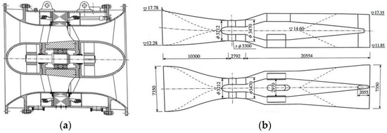
Figure 1.
Tubular pump device [8]. (a) Full tubular pump unit; (b) rear-bulb tubular pump device.
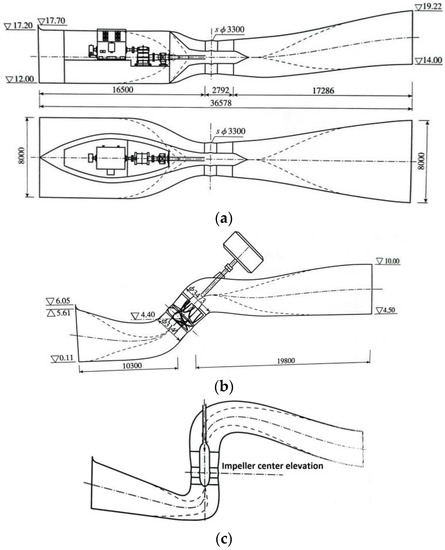
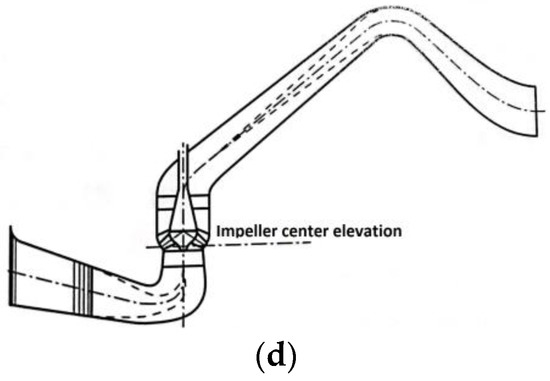
Figure 2.
Shaft extension pump device [8]. (a) Front-positioned-shaft tubular pump device; (b) 45°-inclined shaft extension pump device; (c) vertical axial–flow pump with elbow inlet and low-hump outlet; (d) guide vane mixed flow pump device with elbow inlet conduit and siphon outlet conduit.
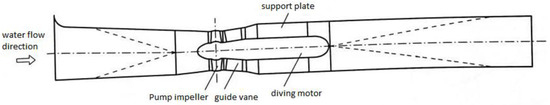
Figure 3.
Submersible pump device (rear motor submersible tubular pump device) [8].
Tubular pump devices include a full tubular pump, bulb pump, and shaft pump, as shown in Figure 1. The full tubular pump device combines the pump and the motor into one, with a compact structure and small axial size. It has the advantages of good water flow properties and low head loss. It is suitable for extremely low lift conditions. The disadvantages are that the insulation grade of the motor’s winding is high and the motor’s efficiency is low. The power unit, bearings, gear box, and other equipment of the bulb tubular pump device are installed in the bulb-shaped metal shell. The main advantages are that the inlet and outlet water flow channels are smooth and straight, and the flow channel’s efficiency is high. The disadvantages are that the power unit and other equipment are arranged in the bulb surrounded by the water flow, so the structure is complex, the motor heat dissipation conditions are poor, maintenance and repair are difficult, the technical requirements are high, and the investment is large. The shaft-type tubular pump device is provided with an open shaft in the inlet or outlet channel, and the power unit, bearings, gear box, and other equipment of the pump unit are installed in the shaft. Compared with the bulb-type tubular pump device, it has the advantages of a relatively simple structure, better motor heat dissipation properties, convenient installation and maintenance, and requires less investment [8].
Shaft extension tubular pump devices include horizontal shaft extension, inclined shaft extension, and vertical shaft extension, as shown in Figure 2. There are many types of horizontal shaft extension pump devices: according to the arrangement of the pump shafts, they can be divided into front shaft extension and rear shaft extension types; according to the way the channel bends, they can be divided into elevation S-shape and plane S-shape types. Their main advantages are that they can obtain better hydraulic performance under low lift, have a simple structure, can be conveniently installed, and provide a good working environment for the motor. Their disadvantages are that the S-shaped bending of the inlet or outlet channel increases the head loss of the channel. The pump shaft of the inclined shaft extension pump device is arranged in an inclined manner. According to the inclination angle of the pump shaft with respect to the horizontal line, there are generally three types of vertical shaft extension pump devices: 15°, 30°, and 45°. The pump room of the vertical shaft extension pump device adopts a layered structure, and the height of the plant is large. It was once called a vertical pump device. The commonly used inlet channel has elbow, bell, and dustpan shapes, and the outlet channel has siphon, low-hump, and straight-pipe types. The vertical pump has the advantages of being a mature technology, convenient installation, stable operation, high reliability, and low maintenance costs. However, the structure of the pump house is complex, the inlet and outlet channels all present 90° turns, and the head loss of the channel is large.
The submersible pump device adopts a submersible motor. The motor and the pump shaft are driven by planetary gears. The water pump, bearings, gearbox, and other equipment form an integrated structure with the motor, which is called a submersible pump, as shown in Figure 3. The submersible pump is divided into horizontal submersible pumps, inclined submersible pumps, and vertical submersible pumps. Compared with the conventional pump device, the submersible pump device has the advantages of a compact structure, convenient installation, and good hydraulic performance.
The transition process of the low-lift pump mainly refers to the start–stop process. Due to the opening and closing of the gate, the sudden change in the flow velocity in the pipeline causes the water hammer phenomenon. This hydraulic process is called the transition process. Experience shows that hydraulic machinery accidents mainly occur in the transition process. Therefore, the study of the start–stop transition process of the pump has an important guiding significance for the safe operation of the pumping station. For the study of the transition process, there are generally three kinds of research: experimental research, theoretical research, and numerical simulation research. This paper reviews the research on the start–stop transition process of large low-head pumps over the past two decades.
The purpose of this paper is to provide researchers in related fields with a more comprehensive overview of the transition process of large low-head pump systems, some of the latest technical means, and possible future development directions. This paper expounds on the research progress, existing problems, and future research directions of pumps’ start–stop transition process, which will hopefully be helpful to future research.
2. Research Status of Transition Process of Low-Head Pumping Station
In the transition process of starting and stopping a low-lift pump, there may be problems such as increased speed and dramatic changes in the pump’s internal and external characteristics, which will produce hydraulic excitation, pressure pulsation, and so on. In the process of starting the pump, because it is necessary to open the gate, and since a quickly opening gate is a common way to stop the flow of the pump device, there will be a matching problem between the fast gate and the runner’s starting speed during the starting process of the pump. For example, consider the starting time of the fast gate and the relationship between the starting speed and the starting time and starting speed of the runner: the phenomenon of water backflow will occur when the fast gate is opened earlier; if it is opened late, the unit head will increase sharply, resulting in the pump’s start failure. In the shutdown process, if power failure occurs due to an accident and the gate closes too late, the operation of the pump station will be the pump conditions in turn through the braking conditions, turbine conditions, and ultimately to runaway. Among these failures, the water backflow caused by the pump’s reversal, which can thus lead to drive motor reversal, will cause water hammer, motor damage, and other accidents. The runaway speed is far greater than the speed under design conditions, and will cause severe vibration of the unit and pressure pulsation [9]. When the unit starts and stops, the drastic change in water flow causes the water hammer phenomenon. Water hammer will cause a sharp change in the internal pressure of the unit, causing damage to the unit’s components and affecting the stable operation of the unit. The authors of [10,11,12,13] studied the pressure fluctuation characteristics of a pump based on the CFD method and observed that the hydraulic excitation force of the pump is the main cause of dynamic stress fluctuation.
2.1. Start-up Process Research
Domestic and foreign scholars have conducted a lot of research on several transition processes of pumps, wherein the pump transition process mainly refers to a pump’s start–stop process. The actions involved in the start-up process of the pump is the start-up of the impeller and the opening of the gate. The different opening times and opening speeds between the two have an important influence on the internal and external characteristics of the pump device during the start-up process. In addition, some gates have also been equipped with patter doors to shunt and reduce the head of the start-up process, which is related to the stability of the unit. The research on the starting transition process of low-lift pumps will help further the development of low-lift tubular pump units, especially in the east route of the south-to-north water transfer project.
To study the evolution of unsteady flow in the start-up process of centrifugal pumps, Z Zhu et al. [14] used the external characteristics test and an internal flow-focused numerical calculation of centrifugal pumps to obtain the relationship between speed, capacity, head, and start-up time through external characteristic experiments. The velocity and pressure distribution in the pump channel was obtained by numerical calculation. The calculation results show that the internal flow characteristics are in good agreement with the experimental results and numerical calculations of the external characteristics, which lays a foundation for the diagnosis of the centrifugal pump during transient operations. Based on the asynchronous starting characteristics of the three-phase salient pole synchronous motor, combined with the hydraulic characteristics of the shaft tubular pump device and the dynamic characteristics of the pump unit, Zhang Jinpeng established a mathematical model of the starting transition process of a shaft tubular pump station [15]. Through Simulink simulation software, various characteristics in the starting transition process were studied in depth. S.F. Fu et al. [16] studied the transient characteristics of an axial flow pump during start-up using sliding mesh and pressure coupling, and the results were in good agreement with the experimental results. The results show that the transient characteristic parameters such as the rotational speed, head, and flow rate of the pump change significantly during the start-up process. The pressure distribution of the impeller blade changes obviously, and the vortex core area increases gradually. Kan K et al. [17] designed and verified a method of reinforcing impeller blade roots to increase the strength of the blades and minimize their impact on hydraulic performance, which can be used to improve the stability of the structural design stage of hydraulic machinery blades. W Li et al. [18] studied the vibration characteristics of the runner during start-up. The results show that the combined effect of the complex hydrodynamic environment and the centrifugal force of the impeller during the start-up and acceleration process makes the deformation and dynamic stress of the blade increase in a reciprocating oscillation trend. The rapid change in the rotational speed exacerbates the vibration problem around the tip area of the blade, which leads to excessive stress concentration and damage at the root of the blade. Li, Z. F. and Hu, F. F. et al. [19,20,21,22] studied the internal flow characteristics of the centrifugal pump during start-up. In order to obtain the internal flow field and observe the evolution of the transient internal flow in the impeller, the three-dimensional unsteady, incompressible viscous flow during the start-up of the centrifugal pump was studied by computational fluid dynamics (CFD), as shown in Figure 4. The dynamic mesh (DM) method with non-conformal mesh boundaries was applied to obtain the external characteristics and internal flow field.
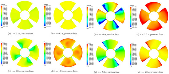
Figure 4.
Pressure change on impeller during startup [16].
The impeller speed and the time and speed of the gate’s opening play a decisive role in the transition process. Long Yun et al. [23] studied the start-up process of a multi-stage centrifugal pump, which is divided into two stages: the closing valve conversion and opening valve conversion. The authors analyzed the characteristics of the pump and the evolution of the internal flow field. Yang [24] studied the influence of the gate-opening speed and opening time delay on various parameters during the start-up process of a tubular pump. The results show that an appropriate acceleration of the gate-opening speed and delay in the gate opening time can improve the starting characteristics of the pump device, which is beneficial to the start-up process. By calculating the influence of the opening speed of the gate on the system under the most unfavorable conditions, Wang Changhong et al. [25] observed that with the extension of the opening time of the gate, the maximum backflow decreases gradually, and the maximum starting power increases gradually. In the case of motor power, the opening time of the gate can be reasonably selected. Xu et al. [26] studied the change in the external characteristic parameters and flow patterns during the start-up process of the gate of a large-scale tubular pumping station unit at 10 times the design speed. It was found that the speed and flow of the unit would reach the rated speed and rated flow faster, but at the same time, the maximum backflow flow increased by 30% compared with the non-accelerated start-up. Ji Y Y et al. [27] studied the hydraulic performance under three states of fast, medium, and slow start-up times at a very low flow rate and revealed the transient characteristics of the pump during start-up. The results show that the similarity law of the pump is suitable for the transient process’s performance prediction with a long start-up time.
As a commonly used flow-breaking device in pumping stations, the flap gate has the effect of shunting and reducing the starting head during a pump’s start-up. Li Yingchao and Xu Hui et al. [28,29] established a dynamic torque balance equation for the hydraulic characteristics of the start-up transition process of the fast gate with the opening of the flap gate. Figure 5 shows the change rule of the gate and flap gate. The results show that the gate with the additional flap gate can reduce the maximum head during the start-up process and can also provde a good diversion effect in order to avoid the instability of the unit caused by the sudden change in pressure on both sides when the gate is opened instantaneously. According to the pump station unit in the start-up process concerning a frequent start-up failure phenomenon, and the analysis of the existence of the asynchronous operation of a motor that cannot move into the synchronization phase, Yu Qiqing [30] put forward research on the fast gate type concerning the feasibility of adding a door, and pointed out that after adding the door, it is appropriate to reduce the lifting speed of the gate and reduce the opening time delay to improve the efficiency of the pump station.
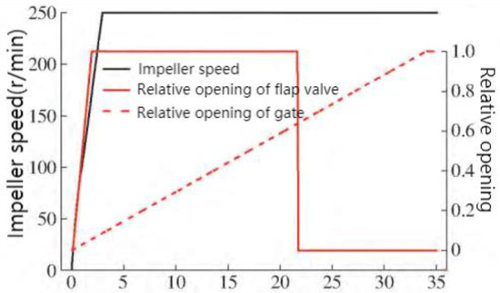
Figure 5.
The variation law of impeller speed, relative opening of fast gate, and flap gate [30].
To investigate the transient characteristics of the large vertical siphon axial flow pump station during the start-up and exhaust process, Zhang et al. [31] numerically simulated the start-up process of an axial flow pump station under the two start-up modes of pre-opening the vacuum-breaking valve and keeping the vacuum-breaking valve closed. The start-up transition process of the siphon axial flow pump from start-up to stable operation is divided into four stages, as shown in Figure 6. The water flow over the hump from the start-up of the unit to the rising of the hump is defined as the hydraulic gas drive stage. The water level from the hump to the bottom of the hump is defined as the weir flow stage. The water level from the bottom of the hump to the top of the hump before emptying is defined as the siphon formation stage. Air discharge in the pump device and the achievement of full pipe flow are defined as the stable operation stage. Wu et al. [32] studied the external transient hydrodynamic performance and internal flow mechanism of the pump during the rapid opening of the discharge valve.
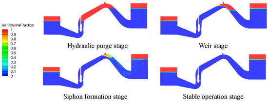
Figure 6.
Stage division in the exhaust process [31].
2.2. Shutdown Process Research
The transition process of a pump’s shutdown includes a normal shutdown and an accidental shutdown. Most scholars study accidental shutdowns, that is, runaway conditions. Runaway means that in the process of stopping the pump, the sudden power failure of the pump unit or other unit causes an accidental shutdown, and the locking device (fast gate, flap gate, etc.) refuses to operate, which will cause the speed to decrease and the flow to decrease. Until a certain time, the flow rate of the unit is reduced to zero, and then the unit enters the braking condition. The water flow flows backward, and the flow rate gradually increases. The unit speed continues to decline until it drops to zero. After that, the impeller begins to rotate in the reverse direction of the turbine, and the speed continues to rise. Finally, it reaches the runaway state. The runaway speed exceeds the rated speed several times, which may exceed the safety range and cause damage to the unit [33]. The four-quadrant operating characteristics of the pump are shown in Figure 7.
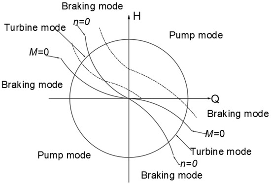
Figure 7.
Four-quadrant operation characteristic curve.
Yang Lin et al. [34] studied the shutdown transition process of large-scale low-lift pumping stations. During the shutdown process, the axial flow pump unit will enter the pump’s working conditions, the brakes’ working conditions, and, in turn, the turbine’s working conditions. After the fast gate is closed, the blade torque and the blade axial force will oscillate, which can easily induce a lift accident. To explore the instantaneous flow characteristics of the pump under unsteady conditions, K Kan et al. [35] used the three-dimensional VOF method to simulate the water surface of the upstream and downstream reservoirs, carried out numerical simulation and model testing on the whole flow channel, and studied the runaway process caused by the power failure of the unit. During the shutdown process, the external characteristic parameters of the unit changed, as shown in Figure 8.
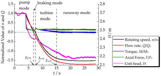
Figure 8.
Time history curves of the key dynamic parameters of the pump during the runaway [35]. process.
The runaway process of a pump-turbine under pump conditions is a rapid transient process. In this process, the vibration of the unit, the fluctuation in the degree of water hammer, and the violent change in pressure pulsation endanger the pump-turbine unit [36]. To simulate the transient flow caused by a pump’s failure more effectively, M. Rohani et al. [37] proposed a point-implicit characteristic method (PIMOC) and improved pump formula. Xu Zhe et al. [38] studied the difference between the forward and reverse runaway transition processes of the bidirectional, low-lift, horizontal axial flow pump device and analyzed it with the entropy production theory. The results show that compared with the head loss obtained by an entropy generation calculation and a model test, the error is within 3% under both forward and reverse conditions, which verifies the accuracy of numerical simulation and entropy generation calculation. Li et al. [39] carried out an unsteady numerical simulation on the runaway conditions of a pump-turbine under different openings and compared it with the experimental results, obtaining the amplitude and frequency of the pressure pulsation. The results show that with the increase in the opening, the speed increases, and the amplitude of pressure pulsation also increases. The main frequency of pressure pulsation in the draft tube has transitivity and the amplitude increases with the flow direction. Using the steady calculation results of the initial working conditions as the initial flow field of an unsteady calculation, Zhou Daqing et al. [40] numerically simulated the power-off and runaway process of the axial flow pump device model and obtained the time required for the unit to reach the maximum speed of 20.35 s. At the same time, they revealed the variation law of the parameters such as the unit speed, flow rate, torque, and pressure corresponding to the measuring point with time and the transient process of the flow field of the meridian section of the flow channel of the device model and the pressure field of the impeller blade. He Zhongwei et al. [41] studied the power-off and runaway transition process of an axial-extension tubular pump device by considering the influence of the inlet and outlet boundary of the pressure along the water depth and the gravity term; analyzing the variation law of the flow rate, rotational speed, and pressure at different measuring points at different times; and comparing them with the real machine test. The results show that the maximum runaway speed is 36.98 s, and the maximum runaway speed is 30.97 rad/s, which is consistent with the experimental measurement.
Z Y Yang et al. [42,43] studied the variation of the pressure pulsation, runner coincidence, and guide vane torque during the runaway process of a pump turbine. Gou et al. [44] numerically simulated the runaway of the pump condition based on the VOF two-phase flow model and the single-phase flow model. It was found that the internal and external characteristics of the power station changed drastically and interacted with each other. The spiral vortex formed by the vortex in the runner in the draft tube is the main reason for the low-frequency pressure pulsation in the runaway condition. Dai et al. [45] analyzed the change in the external characteristic parameters and the evolution of the internal flow field in the runaway transition process of a vertical axial flow pump device and found that a highly spiraled vortex band appeared in the elbow channel during the runaway transition process. L et al. [46] studied and analyzed the pressure fluctuation and wake change of pump turbines during load rejection. Zhang Chenying et al. [47] used the SST turbulence model to simulate the unsteady runaway process of a centrifugal pump and analyzed the pressure fluctuation and vorticity by short-time Fourier transform (STFT) and vorticity intensity, respectively. The results show that when the high amplitude frequency of the pressure pulsation increases, a large area of vorticity appears in the elbow pipe. The main frequency of the pressure fluctuation at the elbow pipe is the blade-passing frequency (BPF). The main reason for the pressure fluctuation is the interaction between the rotor and the stator. X B Li et al. [48] numerically studied the dynamic flow characteristics of the runaway process and analyzed the time–frequency relationship of pressure pulsation by using a fast Fourier transform and a short-time Fourier transform. Time domain and frequency domain analyses are the main methods used to obtain change regulations. Dai Jing et al. [49] also studied the pressure fluctuation characteristics of axial flow pumps under different runaway conditions. The results show that the pressure fluctuation under runaway conditions is mainly affected by the rotating frequency, blade-passing frequency, and wake vortex frequency.
For the safety of the unit, pressure pulsation should be avoided [50]. During the shutdown process, if the gate is closed slowly, water backflow will also occur. If it is closed quickly, it will produce a huge impact force, damage the gate, or cause the pumping station to vibrate violently and produce a great deal of noise. Lu Weigang et al. [51] established a mathematical model of the falling motion of the fast gate based on relevant theories, where the closing time and impact speed can be obtained. Consequently, it was determined necessary to optimize the closing law of the gate. Wang et al. [25] optimized the two-stage closing law of the siphon axial flow pump unit gate and observed that the optimal closing process was 62.5% of the total stroke of the 10 s fast-closing and 37.5% of the remaining 90 s slow-closing processes. Of course, most scholars also adopt a uniform closing law. For the valve-locked pump device, the two-stage closing law [52,53,54,55] is mostly used, which can effectively reduce the incidence of the water hammer phenomenon during an accidental pump shutdown. In addition, the two sections of different pump stations’ fast-closing and slow-closing laws are different, and need to be optimized according to the actual situation.
Most of the numerical simulation studies on the shutdown process adopt the following ideas, as shown in Figure 9.
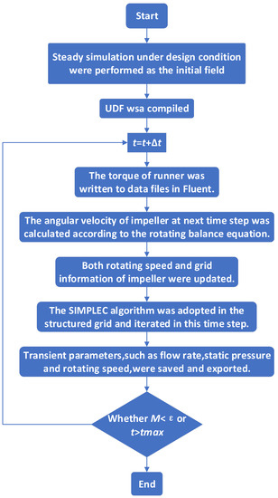
Figure 9.
Algorithm routines of the runaway transient simulation [35].
Regarding a pump in the shutdown process, the unit torque equation is shown in Equations (1) and (2).
In the formula, is the rotational inertia of the unit; is the angular velocity during the unit-closing process; is the torque of the impeller subjected to water flow; is the mechanical loss for the unit; is the unit volume loss; is the time step.
2.3. Flap Gate
The flap gate is one of the ways used to cut off the flow in the operation of pumping stations [56,57], especially in low-lift pumping stations. The flap gate has different types, as shown in Figure 10. After the pump is started, the racket door is opened by the water flow impulse, which can also play the role of shunting in the start-up. After the shutdown, with the decrease in the impact force of the water flow, the flap door falls due to its weight. After the pump is turned to the positive flow, it closes and presses the flow channel in the backflow stage, which plays a role in stopping the flow. Compared with other flow cut-off methods, the flap gate has the advantages of a simple structure, easy-sealing properties, and convenient use, but there are also some shortcomings. For example, in the process of opening, hydraulic loss is caused by the small opening angle. If the flap gate is added to the gate, the situation is better. After the gate is opened, the flap gate does not work; additionally, in the process of a shutdown, the pat door under the weight and water pressure closed will produce a larger impact force on the pat door itself or the hydraulic structures will produce certain harm [58]. In recent years, scholars have conducted some research on the impact of the door [59,60,61,62,63]. We should choose the appropriate door type, structure, and [64,65] corresponding auxiliary system [66,67] to achieve the most effective effect.
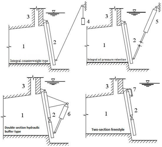
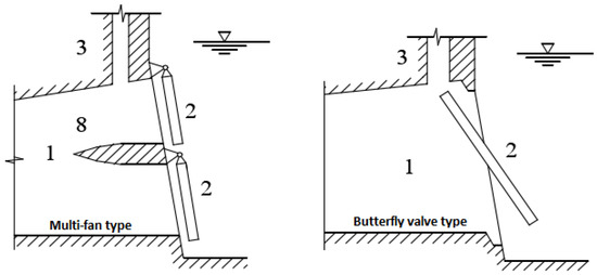
Figure 10.
Diagram of flap valve types [68]. 1—Outlet channel, 2—Flap valve, 3—Vent, 4—Counterweight, 5—Buffer cylinder, 6—Buffer water cylinder, 7—Rocker arm hinge link, and 8—Diaphragm pier.
2.4. Transition Process Accident
The water hammer of a pumping station has a great influence on the normal operation of the pumping station project. Many pumping stations have suffered serious damage due to water hammer. For example, in 1981, a serious explosion occurred in a petrochemical plant due to water hammer. The reason was that the workers erroneously operated the valve. The water hammer pressure destroyed the water pipeline, resulting in the shutdown of several satellite plants in the plant and serious losses. In 1983, due to maintenance negligence, grinding occurred after a water plant in Beijing had installed a pump outlet check valve shaft, wherein the valve disc suddenly fell off, rushed to the valve body contraction outlet, and suddenly blocked the outlet, resulting in a great degree of water hammer. Huge water columns and blown-up lids rushed toward the roof of the multi-meter-high factory building, which was flooded by 10 pumps in half an hour, causing a great impact and the loss of production and life. On 8 July 1985, when the No.2, No.3, and No.4 pump units were running at the same time in Changsha No.5 Waterworks, the power grid was suddenly cut off, and the automatic pressure-holding hydraulic butterfly valve of the three units was closed at the same time. When water hammer was generated, the hydraulic butterfly valve’s body and the valve foundation of unit No.3 were damaged, and a large shutdown event occurred due to flooding [69]. On 17 September 2005, in Yinqian District Thermal Power Engineering’s circulating water pump rooms #1 and #5, the check valve could not achieve slow closure during the circulating pump’s stop process due to pump water hammer and suffered serious damage, specifically, (1) pump foundation cracks, (2) the coupling incurred 3 mm and 8 mm misalignments, and (3) the elastic washer was seriously worn [70]. Around 9:00 on 2 June 2010, the new drainage system in Hejiayan Gold Mine was tested to simulate the sudden interruption of power during the commissioning process. At the moment of power failure, with a loud bang, the stainless-steel buffer at the outlet of the D280 multi-stage pump was seriously pulled up, forming a twist, and a drainage pipeline with a diameter of 273 mm suffered obvious displacement. Multiple welds ruptured, the pump impeller reversed at high speed, and the check valve spool at the pump outlet ruptured. Fortunately, no casualties or flooding accidents occurred. The reason for this pump-stopping water hammer accident was that the ordinary check valve installed at the outlet of the pump did not meet the requirements of the drainage system in terms of pressure strength and structure. Second, the drainage pipeline was not fixed firmly, which is very conducive to pipeline displacement [71]. The pressurized pump station in the water source area of Baotou Steel adopted a horizontal centrifugal pump. In 2000, the pump was started after the preparation of unit #3 before. After the unit started, after about 15 s, water hammer occurred, the cover plate of the outlet pipe trench was lifted, and a large amount of water gushed out. It was judged that the outlet pipe had burst; thus, the suction gate was closed urgently, and all the pumps were stopped. Due to the large amount of water that had discharged from the accident point, when the suction gate was closed halfway, the water in the pump room had risen to the chest of the operator, the personnel were forced to evacuate, and the pump room was flooded. After an analysis, it was determined that the gas in the pipeline had not been exhausted, and the pressurized water valve was opened too fast, so when the pump was started, the pressure and pump speed changed, and the flow rate in the pipeline was greatly increased. At this point, high-pressure water flow—a pressure of 0.9 MPa—was present in the main pipe, and the two water flows acted on the air mass at the same time. With the increase in the compressed air mass, the air mass eventually collapsed, and the two water columns collided with each other, resulting in instantaneous pressure changes, and causing the pipeline to vibrate and form a pump-starting water hammer. The weak links in the pipeline were damaged under the action of pressure from the water hammer [72].
Water hammer accidents often occur in foreign nuclear power plants. In the United States alone, 76 water hammer accidents were reported from 1965 to 1981. In 1985, a huge water hammer hazard occurred in unit #1 of the San Oro Fell Nuclear Power Plant in California, the United States. The accident was due to an electric short circuit that caused the main feed water pump in the secondary circuit to stop the pump and cut off the flow of water. Four minutes later, the operating workers mistakenly operated and started the make-up pump, resulting in a catastrophic water hammer accident. More than 50 m of water supply pipeline incurred seriously distorted displacement, more than a dozen supports were destroyed, displacement of 30 cm was measured, and there was a burst pipe with 2 m long fish mouth cracks; thus, the nuclear power plant was forced to shut down [73]. It is also the effect of water hammer on the pumping station project, which causes serious damage to the pump station hydraulic transition process, that has attracted a great deal of research attention.
3. Transition Process Test Research Method
The research methods of the pump unit transition process mainly include experimental research and numerical calculation. The experimental research includes field tests and model tests. However, the cost of the field test is high, and the test is difficult. The rapid change in the flow velocity and pressure inside the pump device may cause its value to be several times higher than the design conditions, which is more harmful. So, the test is conducted through model experiments, and research is mostly conducted on the hydraulic machinery test bench.
3.1. Field Test Method
Huang Weijun [69] measured the closing process of a butterfly valve in each pump station and the hydraulic transient process of a single unit’s (large and small) sudden shutdown in the second pump station through a field test, which laid a foundation for the correct selection of relevant parameters in the calculation and analysis of the hydraulic transient process in the pump station. Fu, S [16] carried out a field test at a pump station in China. The pump installation is shown in Figure 11. During the transition of the pump, the discharge of the pump was obtained by an electromagnetic flowmeter, as shown in Figure 11a; the HPT3000 pressure-synchronous acquisition system is used to connect the pressure sensor and obtain the signal. The voltage was measured at a sampling frequency of 1 kHz in a 60 s period, as shown in Figure 11b. The CYG1102 pressure sensor arranged above the inlet section of the front guide vane and the impeller inlet section were used to obtain pressure data in the range of 0~100 kPa. The maximum error was less than 0.15%, as shown in Figure 11c,d; more detailed settings can be seen in Figure 11e. The entire start-up process of the axial flow pump takes 35 s. In the first 3 s, the inverter is set to start, and the pump accelerates from zero to 250 r/min and then rotates at a constant speed.
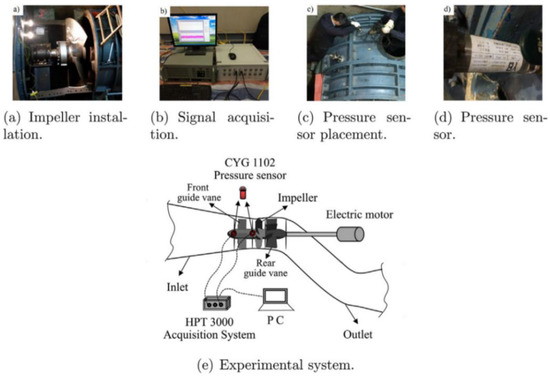
Figure 11.
Field test of Chinese pump station [69]; (a) Impeller installation; (b) Signal acquisition; (c) Pressure sensor placement; (d) Pressure sensor; (e) Experimental system.
By using the field test results of the Huaiyin two-station synchronous motor-starting procedure, Ge Qiang [74] verified the change rules concerning speed, flow, head, torque, and other parameters according to time in the starting transition process of a large synchronous motor and verified the accuracy of the established mathematical model. Three synchronous motors are installed in Huaiyin No.2 Station of the South-to-North Water Diversion Project, with an elbow-shaped inlet conduit and a siphon outlet conduit. The vacuum-breaking valve is used as the blocking device. The pump system of Huaiyin’s second station is shown in Figure 12.
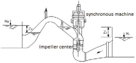
Figure 12.
The pump system of Huaiyin second station [74].
A field test is mainly conducted to test energy characteristics, it has a high cost, is difficult, and poses a certain risk. At the same time, limited by the field conditions, the measuring range is limited, and the internal flow field is difficult to test. Therefore, there are few studies on the transition process through field tests. As for the reduced testing of the on-site transition process, the sharp changes in the flow rate and pressure inside the pump device may cause these values to be several times those specified under the design conditions, which is more harmful.
3.2. Model Test
At present, the function of the foreign test bench is mainly to carry out the pump model test. The famous test bench is the Adelize National Independent Laboratory in Austria. There are many domestic test benches, such as Harbin Dongfang Motor Factory, China Water Conservancy and Hydropower Research Institute, China Water North, Hohai University, Jiangsu University, Yangzhou University, etc., which can carry out high-precision tests and have carried out a lot of research. A model test bench mainly tests the energy characteristics and cavitation characteristics of a model pump device.
F Yang et al. [75] carried out runaway experiments on the tubular pump and vertical axial flow pump systems. The results show that the runaway speed obtained from the model pump system is suitable for conversion to the prototype pump system.
Figure 13 is a multi-functional vertical pump closed test bench of the Fluid Machinery Engineering Technology Research Center of Jiangsu University. Ma Xinhua et al. [76] conducted a performance test on a model pump of a pumping station on this test bench. The pressure and shaft power changes before and after use in the inlet and outlet of the pump device model during the test were analyzed. The changes in the pump and the internal working conditions of the system during the transition from the test system to the stable working condition were discussed. The duration of the whole transition process was more than the 90 s. Chen Chao [77] carried out an energy characteristics test, cavitation characteristics test, and vibration measurement of the pump device model on the hydraulic machinery-based four-quadrant multifunctional test bench of the National Pump and System Engineering Technology Research Center of Jiangsu University and compared it with the numerical simulation results. The test bench is shown in Figure 14.
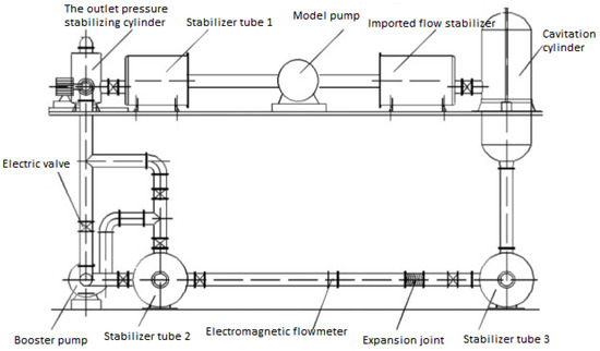
Figure 13.
Multifunctional vertical pump closed test bench [76].
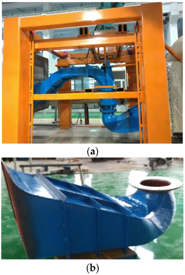
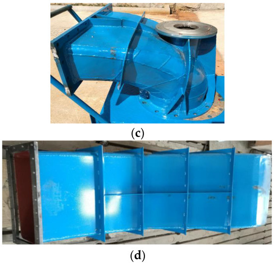
Figure 14.
Mechanical four-quadrant multifunctional test bench [77]. (a) Pump model system diagram. (b) Inlet conduit physical map. (c) Outlet bend physical map. (d) Physical drawing of the outflow channel.
Y. Wang et al. [78] established a test system to investigate the transient characteristics of an ultra-low specific-speed pump during startup. The model test was completed on a closed pump test bench at the National Pump Engineering Center of Jiangsu University. It consists of a cavitation tank, vacuum pump, valve, turbine flowmeter, buffer tank, and test pump, as shown in Figure 15, Figure 16 and Figure 17. The vacuum degree of the pump inlet is adjusted by the vacuum pump. At the same time, import and export pressure, shaft power, speed, and other test data are recorded.
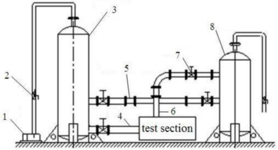
Figure 15.
Schematic diagram of the transient characteristic experimental set-up [78]. 1. Vacuum pump; 2. Ball valve; 3. Cavitation-tank; 4. Water inlet; 5. Turbine flowmeter; 6. Water outlet; 7. Butterfly bumper; 8. Buffer tank.
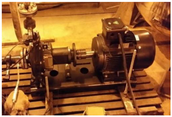
Figure 16.
The model pump [78].
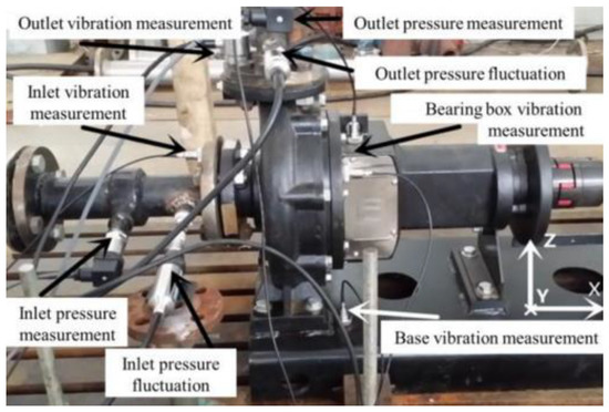
Figure 17.
Sensor measurement point layout [78].
Qiao et al. [79] designed different experiments and studied the external transient hydrodynamic performance and internal flow of a pump during a transient start-up through experiments and simulations. The experimental design is shown in Figure 18 and Figure 19, and the method of measuring flow in the experiment is shown in Figure 20. The contents and results of this paper are significant for the performance prediction of transient pump valves during start-up.
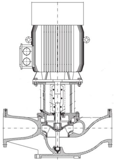
Figure 18.
Illustration of the experiment pump (vertical pipe pump) [79].
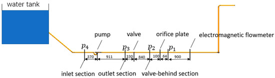
Figure 19.
Diagram of the experiment (units are mm) [79].
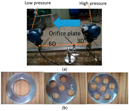
Figure 20.
Illustration of the local resistance flowmeter [79]. (a) The schematic diagram. (b)Three sizes for the orifice plate.
Lu et al. [80,81] used model testing to study the external characteristics of the shaft tubular pump device of Shenjiang Pumping Station and proposed an optimization scheme to improve the rated speed of the pump device. It was verified that the energy characteristics, cavitation characteristics, and runaway speed characteristics corresponding to the design head of the pump device at the new speed meet the requirements. The pump device model test of the Shenjiang pump station was carried out on the pump station test bed of Yangzhou University. The inlet and outlet flow facilities of the test pump of the pumping station test bench can be closed and opened. This analysis is a test of conventional energy characteristics, cavitation characteristics, and runaway characteristics. According to the task requirements, the test adopts a closed arrangement. The test bench is a plane layout, which is composed of a hydraulic circulation system, power and control systems, and a measurement system. The hydraulic system includes an 80 m3 open reservoir, 25 m3 vacuum (pressure) box, 2 m × 2.0 m × 4.0 m movable steel box, 25 m3 pressure box, φ500 return pipe, 60 m3 water-regulating pool, etc. Regarding power equipment, in addition to the 40 kW power unit, there is a 30 kW tubular auxiliary pump and a vacuum pump. The pump device model is shown in Figure 21.
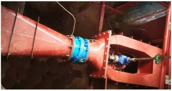
Figure 21.
Model drawing of pump installation [80,81].
The model test also has some limitations. It is difficult for the fluid–solid coupling and modal analyses calculated by a computer to be verified by the test results, indicating that the existing test technology lags behind the three-level technology and cannot meet specifications. In terms of stability, only the degree of pressure pulsation is measured in the model test; there is no rigid assessment index, there is not enough theoretical support for the conversion between the prototype and the model, and the stability of the real machine cannot be accurately predicted according to the results of the model test [82].
In model tests or field tests, flow field-testing technology has become an important means of conducting a successful test. The two most commonly used methods are to measure the velocity of a fluid passing through a point in space and to measure the distance of a particle in the fluid flowing through space per unit of time, or the time required to flow through a fixed distance. The former constitutes the use of a current meter to measure— including the electromagnetic velocimeter using the principle of electromagnetic induction—the hot wire current meter using the principle of heat conduction, etc. The latter constitutes the measurement of the flow rate by placing tracers in water, similar to particle image velocimetry.
Particle Image Velocimetry (PIV) technology is a transient, multi-point, non-contact fluid mechanics velocity measurement method, as shown in Figure 22. Some tracer particles with good tracking and reflection properties are scattered in the flow field, and the laser sheet light is used to illuminate the section area of the measured flow field. The particle images of two or more exposures are continuously taken by the imaging recording system, and then the PIV images are analyzed by the image cross-correlation method. The average displacement of the particle image in each small area is obtained, and the two-dimensional fluid velocity distribution of the whole area of the flow field section is determined.
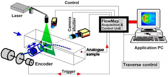
Figure 22.
Particle image velocimetry technique (The figure is from https://zhuanlan.zhihu.com/p/446486019 accessed on 2 November 2022.).
Grzegorz Ligus et al. [83,84,85] measured the data of two-phase fluid flow by using a high-speed camera and particle image velocimetry in experimental research and verified the accuracy of the model. Xu et al. [86,87] studied and analyzed the generation mechanism and development law of a vortex structure in the internal flow field of the vaneless zone of a pump-turbine and its pressure pulsation in the vaneless zone in detail by particle image velocimetry (PIV) test technology. The PIV test site is shown in Figure 23.
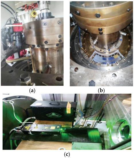
Figure 23.
PIV test site [87]. (a) Camera placement position (b) Transparent glass window. (c) Laser incident window.
4. Numerical Calculation Method
At present, the numerical solution of the transient process can be divided into the numerical solution of the external characteristics based on the comprehensive characteristic curve of the turbine model and the boundary conditions and the numerical solution of the internal characteristics based on the analysis of the internal characteristics of the turbine. The former is a traditional method, and the latter is a new method that has emerged in recent years. Most of the existing research is based on one-dimensional flow theory, which has obvious limitations [88]. There have been few achievements in the study of the transition process of pump devices by using three-dimensional flow theory.
4.1. Numerical Solution of External Characteristics
The numerical solution of external characteristics requires a large number of data on the comprehensive characteristic curve of the turbine model, which is solved by the one-dimensional characteristic line method [89,90,91]. The characteristic line method is a numerical calculation method. The main idea is to transform the basic equations of water hammer expressed in the form of partial differential equations into ordinary differential equations in the direction of the characteristic line, integrate them along the characteristic line to obtain the finite difference equation, and then use the finite difference numerical calculation. The basic equation set of the water hammer consists of a continuity Equation (1) and a momentum Equation (2), which are mainly employed to solve the flow velocity V and water head H in the equation set. Before the 1940 s, the basic equations for describing water hammer were solved mainly by an electrical algorithm and a graphic method. However, these two methods can only solve relatively simple boundary conditions, and the workload is large while the accuracy is low. With the rapid development of computer technology, the use of numerical methods to solve the above equations has gradually become the main calculation method. Among them, the characteristic line method based on the principle of numerical calculation is one of the important solutions. The characteristic line method can not only calculate the surge water level fluctuation process of the surge shaft but also the pressure of each calculation section of the pressure pipeline, and it can calculate the transition process of the hydro-generator unit. At the same time, it can complete the calculation of the power station regulation guarantee and the calculation and analysis of the small fluctuation stability. Therefore, the characteristic line method plays an important role in the calculation of the transition process.
The flow continuity equation in the diversion pipe is shown in Formula (3)
The flow momentum equation in the diversion pipe is shown in Equation (4)
where is the water hammer wave velocity; is the flow velocity; is the head; is the angle between the pipeline axis direction and the horizontal line, in which the units are in radians; is the friction coefficient along the pipeline; and is the pipeline diameter.
In the research conducted by Li Cixiang [92], based on the external characteristics method and starting from the variable frequency speed regulation characteristics of the pump unit, combined with the full characteristics of the pump, the hydraulic characteristics of the pump system, the opening and closing characteristics of the fast gate, and the characteristics of the split valve, a mathematical model of the transition process of the variable frequency variable speed bulb tubular pump is established, and the transition process of the variable frequency soft start and soft stop of the Huaiyin No.3 Station of the East Route of the South-to-North Water Diversion Project is simulated by programming. Based on the mixed-pipe characteristic line method, Chen [93] linked the mathematical model of the water diversion system with the boundary conditions of upstream and downstream reservoirs surge chambers, valves, and units; established a mathematical model for the analysis of the transition process of the water diversion system of a pumped storage power station; and calculated and analyzed the transition process of the water diversion system of an actual pumped-storage power station. Hong et al. [94] selected the appropriate surge shaft structure size and reasonable turbine guide vane opening and closing times through a hydraulic calculation of the characteristic line method for the surge shaft of a hydropower station. Guo Jianping et al. [95] used the characteristic line method to establish a mathematical model to analyze the sensitivity of the transition process under various combined working conditions and selected the 40 s two-segment broken line ball valve closing law, the minimum section diameter of the surge shaft, and the minimum value of the unit’s moment of inertia that met the calculation conditions. Wang Shanghong et al. [25] established a mathematical model based on the theory of rigid water hammer and full pump characteristics and obtained an optimization law for the gate’s closing by programming the objective function and constraint conditions. A genetic algorithm was used to solve the optimal closing law of the fast gate, which was 62.5% of the total stroke of the 10 s fast-closing and 37.5% of the remaining 90 s slow-closing processes. Zhou et al. [96,97] established a mathematical model of the starting and stopping process based on the comprehensive characteristic curve of a pump’s operation and torque equation and studied the starting and stopping transition process of the large vertical axial flow pump station, providing reasonable suggestions for the design and operation of a pump station. Chen Songshan et al. [98,99] simulated the transient process of the starting and stopping of a pump unit by establishing a mathematical model of finite difference nonlinear equations of starting and stopping the process of the low-lift pump unit and solving the equations by the Newton–Raphson iteration method. Yao et al. [100] established an water hammer accident analysis and calculation model for the water hammer characteristic line method used in a large battlefield pumping station. Through calculation-based analysis and a field investigation, they found the cause of the failure of the pressure pipeline when the pump was stopped.
4.2. Numerical Solution of Internal Characteristics
The numerical method based on external characteristics has been commonly employed in previous years, which mainly relies on the full characteristic curve for its solutions, entailing a particularly large workload, incurring difficulties in simulating the three-dimensional gravity field [101,102,103], and incurring a large error in the transition process of solving problems related to the low-head tubular pump. With the development of computer technology, in recent years, the research on the transition process of water pumps has mostly adopted the method of three-dimensional numerical simulation [104]. This method is closer to reality and its calculation is more accurate, and it has been applied by many scholars. The numerical solution of the internal characteristics is established for the dynamic working conditions of the prototype turbine in the transient process, and the nonlinear equations related to the position of the regulating characteristics are established. According to the variation law of the displacement of the regulating element with time, the solution of the nonlinear equation is obtained by the numerical calculation method. This method does not necessitate the use of the comprehensive characteristic curve of the turbine model. Furthermore, the turbine regulation and maintenance calculation can be carried out, and the accurate calculation results of engineering practice can be obtained. Therefore, the numerical solution of a pump’s internal characteristics is the most practical method in engineering.
At present, many scholars have verified the feasibility of numerical solutions based on internal characteristics [105]. Ge et al. [106] studied the starting transition process of large tubular pump stations by combining theoretical analysis with simulation calculation, which has a guiding significance for the safe and reliable operation of tubular pump stations. Y Yang et al. [107] used one-dimensional and three-dimensional methods to simulate the rapid runaway process of a pumped storage device with a water head of 700 m after tripping because the one-dimensional method could not obtain the pressure pulsation and the force on the runner. Liu et al. [101] used the numerical calculation method based on internal characteristics to calculate the load rejection transition process of the bulb tubular turbine device to solve a problem in which the transition process could not be calculated without the full characteristic curve. The results show that the error between the calculated value and the measured value is small, which meets the engineering needs. During a power failure, the parameters of the pump fluctuate greatly over time and this fluctuation can cause the vibration of the pump system. Feng Jianjun et al. [108] simulated the transient process of the centrifugal pumps caused by power failure based on ANSYS CFX. By using user-defined functions, the angular momentum equation for calculating the rotation speed of the pump was solved iteratively. At the same time, experimental research was carried out to verify the accuracy of the numerical simulation. The results show that the characteristic curve and runaway parameters of the pump predicted by the numerical simulation are consistent with the experiment, indicating that the numerical simulation method can be used to solve the power-off process of the pump, as shown in Figure 24.
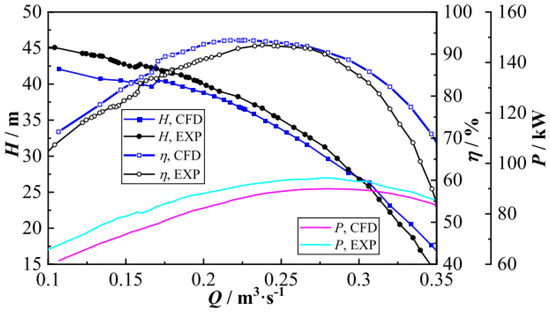
Figure 24.
Characteristics of the pump [108].
Li Jinwei et al. [109] calculated the three-dimensional unsteady turbulent flow in the runaway transition process of the Francis turbine based on the internal characteristic numerical method and compared it with the experimental results. The results show that the two are in good agreement. Based on a three-dimensional unsteady numerical simulation, Zhang et al. [110] studied the transient characteristics of the runaway process caused by the power failure of a pumped storage power station and compared them with the experimental data. The results show that the flow characteristics change dramatically during the runaway process, and the pressure pulsation frequency is related to the runaway speed. Li et al. [111] studied the three-dimensional, unsteady, incompressible, viscous flow of a centrifugal pump during rapid start-up. Comparing the simulation results with the experimental results, the feasibility of a three-dimensional numerical simulation of the transition process was proven. Thus, the numerical solution based on the internal characteristics is accurate and has practical value, but the transition process involves the whole device, so the calculation time is long.
4.2.1. Sliding Mesh
The sliding mesh technique uses two or more computational regions, each of which can generate meshes independently. Each region has at least one interface with adjacent regions. The interface between adjacent computational regions forms a ‘grid boundary’, and the motion domain moves along the interface. The grids on the interface do not need to be aligned, and the flux is realized by the interpolation of information between nodes. When using sliding mesh technology for a numerical simulation, the model needs to be divided into two parts, namely, a rotor part and astatic part, and the two parts mesh separately. Sliding mesh technology is a calculation method applied to the motion of a rotating region in a transient calculation. The motion of the rotating region can be controlled by loading UDF. The sliding mesh method does not involve the deformation and regeneration of the mesh, but it involves the setting of the interface. Compared with the dynamic mesh, this method is not as prone to mistakes. Therefore, the dynamic mesh is usually not used when the sliding mesh method can be used. The rotation of the impeller involved in the transition process of the pump mostly adopts the sliding mesh method.
Dazhuan Wu et al. [32] verified the accuracy of using the sliding mesh method to simulate the valve-opening process through experiments. S.F. Fu et al. [16] studied the transient characteristics of an axial flow pump during the start-up process by using the sliding mesh and pressure coupling, and the results were in good agreement with the experimental results. The results showed that during the start-up transient process, the transient characteristic parameters such as the pump speed, head, and flow rate changed significantly; the pressure distribution of the impeller blade changed significantly; and the vortex core area gradually increased.
K Kan et al. [35] used the sliding mesh method in the impeller area, whereby the change in the rotation speed was calculated by the moment balance equation and a numerical calculation of the pump shutdown process was carried out.
4.2.2. Dynamic Mesh
The dynamic mesh model can be used to simulate the problem wherein the shape of the flow field changes with time due to boundary motion. When using the dynamic mesh model, the initial mesh, the way the boundary moves, and the area involved in the movement are first defined. The boundary-type function or UDF can be used to define the movement of the boundary. The update process of the mesh is automatically completed by the FLUENT program according to the change of the boundary in each iteration step. Many scholars have adopted dynamic mesh technology in the calculation of the transition process
Hua Ye [112] simulated the closing of a valve based on dynamic mesh technology and calculated the flow field at the valve. Compared with the experimental results and the calculation results concerning water hammer obtained via the characteristic method, the results show that the transient simulation using the dynamic mesh technique can better reflect flow field changes. Xu Jianye et al. [113] used dynamic mesh and UDF custom technology to carry out a three-dimensional transient numerical simulation of the runaway condition of an axial flow pump device, and the dynamic characteristics in the flow channel could be obtained intuitively. Liu et al. [114] used fluid coupling and dynamic mesh methods to simulate a hydraulic turbine and explained the flow principle of abnormal phenomena in the transient process. X X Zhang et al. [89] used the (1-D–3-D) coupling method and dynamic mesh technology to simulate the transient process of the Francis turbine under load rejection conditions. Z F Li et al. [19] experimentally and numerically studied the transient characteristics and flow of a centrifugal pump during startup based on two-dimensional particle image velocimetry. A dynamic mesh method combined with a non-conformal mesh boundary was proposed to solve the transient flow dynamic slip zone caused by starting the impeller. Based on the UDF in FLUENT software, Xu et al. [26] controlled the start-up of the gate and used layer-dynamic grid technology to control the grid’s generation and elimination at the gate. The S-A turbulence model was used to study the external characteristic parameters and flow pattern changes during the rapid start-up of the gate of a large tubular pumping station unit. Based on the layering mesh and dynamic mesh technology, as shown in Figure 25, using the moment balance equation to derive the real-time speed of the impeller, Xu Hui et al. [29] numerically simulated the three-dimensional transition process of the full-flow system of a shaft extension tubular pumping station, and the motion law of the outlet channel gate with an additional flap gate was studied.
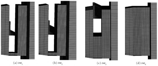
Figure 25.
Grid motion of outlet channel gate with additional flap gate [29].
Li Yiming [115] used the semi-implicit method to solve pressure-coupling equations and the dynamic mesh technology to simulate the three-dimensional, dynamic numerical simulation of the start-up process and runaway process of the bulb turbine. The transient change in the pressure field and the flow characteristics of the flow field in the flow channel of the bulb turbine were obtained, and the change law of the flow field in the transition process was revealed. Wang et al. [116] proposed a method for generating structured dynamic grids. Compared with unstructured dynamic grids, structured dynamic grids solve the problem of negative volumes at gaps and improve calculation accuracy, as shown in Figure 26 and Figure 27. An unstructured dynamic mesh appears in the calculation process: it is difficult to control the mesh quality in the process of mesh reconstruction, while it is easy to produce negative volume at the meshing gap due to mesh inconsistency; consequently, the calculation will be terminated. There is usually only one layer of the grid at the meshing gap, which affects the accuracy of the calculation. Due to the number of grids and the density, is difficult to control shortcomings. The newly proposed structured dynamic mesh can realize the mesh refinement of the fluid region at the meshing clearance and improve computational accuracy and determine the grid control number; additionally, the nodes of all the grids have definite motion laws, and the quality of the dynamic grid is good. Furthermore, the proposed method possesses the advantage of a fast calculation speed.
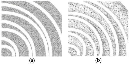
Figure 26.
Unstructured dynamic meshes [116]. (a) Initial grid; (b) reconstructed grid.
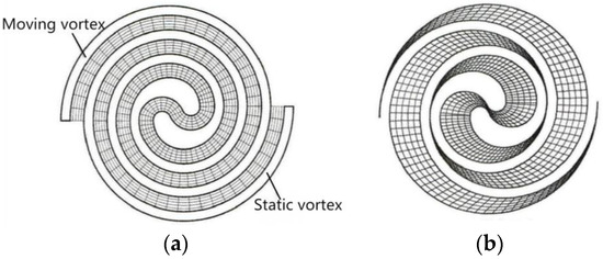
Figure 27.
Structured dynamic meshes [116]. (a) Mesh generation; (b) mesh movement.
Hao Jiguang et al. [117] carried out a comprehensive analysis of various dynamic mesh techniques in computational fluid dynamics, proposed a dynamic mesh-updating technique using the domain dynamic stratification method, and applied this method to a numerical simulation. The results show that the method is accurate and feasible. The accuracy of the results is high, and the dynamic mesh application in the case of a complex shape flow field can be realized. Compared with the local mesh reorganization method, the numerical simulation speed can be accelerated by about two times.
In the calculation of the transition process of a pump device, the dynamic grid is mainly used in the opening and closing of the gate. At this time, the layer grid is used to control the generation and elimination of the grid to complete the opening and closing process of the gate. However, it should be noted that when the layer grid is used, the calculation grid should be a structured grid, and the gate cannot be completely closed, which will lead to calculation errors. Therefore, it is necessary to leave a very small gap to ensure the calculation, so it is impossible to simulate the situation of complete closure. However, through the improvement of the computer version employed, a Gap model has been proposed for 2022R1, which can simulate the complete closing of the gate. The principle is that when the distance between the two surfaces is less than a certain value, there is no fluid flow between them, that is, the gate is closed. However, the gap area using this model incurs a sudden change in the flow rate, which will cause the calculation to be extremely unstable. In practical applications, the flow-modeling type is often used, and a minimal leakage is specified so that the calculation is more robust and more in line with the actual situation. Secondly, the dynamic mesh can also be applied to the movement of the guide vane, the rotation of the runner, etc. At this time, mesh smoothing and mesh reconstruction need to be applied to dynamic mesh. It should be noted that when using this method, the calculation mesh needs to be a triangular or tetrahedral mesh to facilitate the deformation of the mesh.
4.2.3. Boundary Conditions
The pump station transition process involves the opening and closing of the gate, which is closely related to the upper reservoir and the lower reservoir. To study the pump station transition process, most scholars have established the upper and lower reservoirs in a model to simulate the actual situation more realistically. Since the low-lift pump’s lift is low, the effect of gravity should be considered. Liu Yanze and Chang Jinshi studied the influence of the gravity field on bulb-tubular turbines. Due to the uneven pressure distribution in the direction perpendicular to the axis of the unit, there is alternating stress on the blade. The bulb-tubular turbine is also used in instances of low head and it has a reference value to the low-lift pump [102].
For the setting of the inlet boundary conditions, to achieve results closer to reality, the three sides of the reservoir should be set to pressure-intlet, and the pressure changes along the water depth and the top of the reservoir should be set to the open side, where there is an interface between water and air, known as the free surface [118]. Zhao Yaping et al. [119] studied the performance of a turbine with and without considering the free surface and the gravity of the water flow in the reservoir area. The results show that under the influence of the free surface and the gravity of the water flow, the flow in the inlet section of the tubular turbine shows obvious inhomogeneity, as shown in Figure 28. The pressure distribution in the turbine increases gradually from top to bottom, as shown in Figure 29. The blade undergoes periodic pressure fluctuations during rotation; the blades at different positions produce different torques on the shaft, and the output and efficiency of the turbine decrease greatly. It can be seen that the free surface and gravity have an important influence on the turbine. To establish a suitable numerical prediction model, Kan et al. [120] applied two water surface treatments for the upstream and downstream reservoirs, namely, the volume of fluid (VOF) method and the rigid cap hypothesis (RLH) method, and compared the corresponding results. The transient characteristics of the system during power failure were predicted. The maximum runaway velocity obtained by the VOF method was closer to the experimental results. The variable speed of the dynamic parameters of the VOF method is slower than that of the RLH method, and the peak static pressure is smaller. The VOF method is used to analyze the hydrodynamics of the free surface of the reservoir, which makes the water flow in the reservoir relatively stable, while the RLH method causes a large-scale vortex in the reservoir.
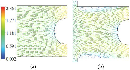
Figure 28.
Velocity vector at the turbine inlet [119]. (a) Without considering the free surface; (b) considering the free surface.
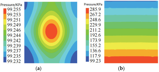
Figure 29.
Pressure distribution at the inlet of the turbine [119]. (a) Without considering the free surface; (b) considering the free surface.
At the same time, the height of the free surface also has an important influence on the calculation. Tension et al. studied the influence of different free surface heights on the flow around the cylinder and the wake vortex morphology. The results show that the drag coefficient decreases with the increase in height, while the lift coefficient shows a contrary trend. The disturbance effect of the free surface on the formation of the vortex behind the cylinder is weakened. It can be seen that the height of the free surface does affect the flow. Therefore, we should select the appropriate free surface height [121].
When considering the free surface and flow gravity, the initial flow field of the pump should be shown in Figure 30, where the blue region is the initial position of water, and the red region is the air region. The inlet and outlet boundary conditions correspond to the pressure inlet and outlet along the water depth, and the air area at the top of the pool is set as an open surface with a water volume fraction of zero [35].
Figure 30.
The initial flow field of the calculated domain [35].
Since the calculation of the pump transition process is related to the free surface, a multiphase flow model is needed. In numerical simulations, the commonly used multiphase flow model is the VOF model, which is suitable for a flow with a clear phase interface [122,123]. In the study of the transition process, the most commonly used turbulence model for pump calculation is the realizable model, followed by the turbulence model. Some scholars use the RNG model, S-A model, LES model, and DES turbulence model. The realizable model can be effectively applied to various types of fluid simulation, including rotating uniform shear flow, pipe flow, boundary layer flow, and flow with separation. The advantage of the turbulence model is based on the improvement of BSL, which simplifies the model and reduces the amount of calculation. The advantage of the RNG turbulence model is that it corrects the dissipation rate equation and performs better than SKE in problems such as complex shear flow, large strain rate, vortex, separation, and other flow problems. In the calculation of the transition process, a good turbulence model must be selected to carry out a reliable numerical simulation. Many scholars have compared different turbulence models [124,125,126,127,128,129,130]. Mao, J et al. [131] selected four widely used turbulence models, k-ε, k-ω, RNG k-ε and SST k-ω models, and compared the three-dimensional steady-state numerical simulation of a large annular vortex pump. To study the transition process of the gas–liquid two-phase flow in a centrifugal pump, Zhong et al. [132] studied a model pump. At the same time, the Eulerian–Eulerian heterogeneous flow model and turbulence model were used to simulate the transition process of the gas–liquid two-phase flow in the pump. The experimental results verify the accuracy of the numerical model for studying the two-phase flow transition process in the pump, reveal the flow law of the transition process in the pump, and determine the criterion for the end of the gas–liquid two-phase flow transition process in the pump. Yang Xiaochun, He Zhongwei, and Yang Lin et al. used a realizable model, and Xu Hui, Chen Xiyang, and Xu Zhe et al. used a turbulence model [133,134,135,136]. Therefore, the most widely used turbulence models are the realizable model and the turbulence model.
4.2.4. User-Defined Functions
In the study of the starting and stopping transition processes of the low-head pumps, the movement of the impeller and gate are involved. The basic parameter setting of FLUENT cannot realize its dynamic movement process, and it needs to use the user-defined (UDF) function of FLUENT. UDF is a program allowing for interaction between users and software, which is mainly realized by a program written in the C language and the DEFINE macro function of FLUENT. The basic functions of UDF include defining boundary conditions, defining initialization conditions, and improving and supplementing models. There are two kinds of UDF macros: interpreted and compiled. The transition process mainly adopts the compiled UDF macro function. The Profile function in the UDF macro is used in the boundary condition of the pressure inlet’s pressure alongside the water depth change. The ZONE _ MOTION function in the UDF macro is used to determine the speed of the pump impeller. The guide vane action can use the CG _ MOTION function in the UDF macro to control the guide vane rotation and use the CG _ MOTION function in the UDF macro to control the opening and closing process of the fast gate. UDF can also be used to read the values of each parameter calculated by FLUENT at each time and return to solve other parameters.
In CFX, there are also user-defined functions. CEL (CFX Expression Language) is embedded into CFX as an explanatory and illustrative language. It has the functions of defining the properties of materials, setting complex boundary conditions, and monitoring a certain amount of the calculation process. The secondary development of CFX by CEL can also be used to study the start–stop process of the pump.
5. Conclusions and Prospect
This paper summarizes the research status of the transition process of large, low-lift pumping stations and introduces the developments of the past two decades in detail from the research content to the research methods. For the calculation of the transition process of a long-distance water pipeline, it is more convenient to use the characteristic line method, but there is also a shortcoming where the full characteristic curve data are lacking and cannot be calculated. If more attention is paid to the change of the flow pattern in the transition process, the three-dimensional numerical simulation method should be adopted. FLUENT, CFX, and other software can be used.
- (1)
- In the start-up stage, centrifugal pumps, axial flow pumps, bulb-tubular pumps, shaft-tubular pumps, and so on are the most studied, which all involve increasing the impeller speed. The sliding mesh method is mainly used, and the dynamic updating of the mesh will lead to a decrease in the mesh quality. Therefore, the sliding mesh method is the main method to control the impeller speed. A tubular pumping station will also involve the opening of the gate. The opening time and speed of the gate are related to the success of the start-up. If the gate is opened late, the head of the unit rises sharply in a short time, thereby leading to the failure of the start-up. If the gate is opened early, backflow will occur. To prevent the start-up head from being too large, the flap gate can be set for diversion, thereby reducing the start-up head. The siphon axial flow pump station is special, and its start-up transition process is divided into four stages: the hydraulic gas drive stage, the weir flow stage, the siphon formation stage, and the stable operation stage.
- (2)
- During the shutdown process, the main cut-off mode of the pump station is the fast gate. If the gate closed too fast, it will produce a large impact, damage the gate, or cause a pumping station’s violent vibration; if the gate is closed too slowly, it will cause a water backflow phenomenon, resulting in runaway. Optimizing the gate-closing law to ensure that no runaway occurs during the shutdown is our main research task.
- (3)
- The research on the transition process is mainly based on the combination of numerical simulations and experiments. The reliability of a numerical simulation is verified by an experiment. A numerical simulation can measure some parameters that cannot be measured by an experiment. For the study of the transition process, most scholars focus on the study of the change in the external characteristic parameters and the internal flow pattern and pressure pulsation during the start–stop process, how to determine the time of the transition process, and how to select the impeller and the gate. The most suitable speed time-matching procedure is still meagre, and future research should be directed in this direction to ensure the best opening and closing laws.
- (4)
- The realizable model and SST turbulence model are widely used in calculation. The inlet and outlet boundary conditions are mostly the mass flow inlet, the pressure outlet, or the pressure inlet and outlet. Due to the characteristics of the low-lift pumps, the influence of gravity is considered. The solution algorithm can use SIMPLE, SIMPLEC, and Double methods, but the most commonly used is the SIMPLEC method. The layered grid in the dynamic grid based on UDF control is used to control the opening of the gate, and the sliding grid method controlled by UDF is used to control the change in speed. The three-dimensional numerical simulation also has some shortcomings. It relies too much on the experience of the calculator. The selection of the turbulence model, boundary conditions, control methods, etc., is an important part of the calculation process. Secondly, it also relies on a powerful computer system. The transition process of the whole device takes a long time and requires a long calculation time as well. The improvement of calculations and the continuous optimization of the calculation methods constitute the development direction for CFD numerical simulation technology in the future.
- (5)
- To ensure the normal operation of the pumping station and prevent the occurrence of water hammer accidents, it is not only necessary to design the best opening and closing times and an optimal operation law of the gate of the pumping station but also to select excellent water hammer elimination equipment in the design of the pumping station. It is necessary to ardently prevent power failure, to regularly patrol the line tower, and to accurately measure grounding resistance and insulation resistance. The hidden dangers of the lines inside the plant must be inspected in a timely manner. During operations, the personnel on duty should maintain good records of the inspection of each distribution room in order to find and solve problems in advance.
Author Contributions
Data curation, H.C.; formal analysis, J.Z. (Jian Zhang); investigation, D.L.; writing—original draft preparation, J.Z. (Jing Zhang); writing—review and editing, X.G.; supervision, Y.Z. All authors have read and agreed to the published version of the manuscript.
Funding
This research was funded by the National Natural Science Foundation of China (Grant Number: 52279083, 52006053).
Conflicts of Interest
The authors declare no conflict of interest.
References
- Research Group of Development Research Center of Ministry of Water Resources. Deeply Understanding the Significance of South-to-North Water Diversion Project and Firming Four Lifeline. China Water Resour. 2022, 11, 4–9. [Google Scholar]
- Li, M.; Yang, N. South-to-North Water Diversion: Lifeline of Optimizing Water Resources Allocation. Sustainability 2019, 11, 3735. [Google Scholar] [CrossRef]
- Luo, L.; Liu, D.-X.; Yan, L.-L. Exploration of the thought of coordinated water resources utilization of the South-to-North Water Diversion Project in the Beijing-Tianjin-Hebei Region. China Water Resour. 2022, 13, 47–49. [Google Scholar]
- Intriago Zambrano, J.-C.; Michavila, J.; Arenas Pinilla, E.; Diehl, J.-C.; Ertsen, M.-W. Water Lifting Water: A Comprehensive Spatiotemporal Review on the Hydro-Powered Water Pumping Technologies. Water 2019, 11, 1677. [Google Scholar] [CrossRef]
- Xu, L. Study on Hydraulic Performance Optimization and Comprehensive Comparison for Large Especial Low Head Pump System; Yangzhou University: Yangzhou, China, 2012. [Google Scholar]
- Shi, L.J.; Jiao, H.F.; Gou, J.L.; Yuan, Y.; Tang, F.P.; Yang, F. Influence of Backflow Gap Size on Hydraulic Performance of Full-flow Pump. Trans. Chin. Soc. Agric. Mach. 2020, 51, 139–146. [Google Scholar]
- Li, L.; Wang, Z. Numerical simulation of 3d viscous flow in tubular pumping station on dual-directional operation. Chin. J. Mech. Eng. 2007, 43, 62–66. [Google Scholar] [CrossRef]
- Lu, L.-G. Optimal Hydraulic Design of High Performance Large Low Head Pump; China Water & Power Press: Beijing, China, 2013. [Google Scholar]
- Wang, D.-L. Causes and Elimination Measures of Pump Vibration. Water Supply Drain. 1996, 22, 3. [Google Scholar]
- Fang, G.-C.; Yang, J.-F.; Kan, K.; Duan, H.-L.; Guo, H.-J.; Zheng, Y. Hydraulic Stability and Dynamic Stress Analysis of Large Shaft Tubular Pump under Multiple Working Conditions. Yangtze River 2021, 52, 317–321. [Google Scholar]
- Wang, X.; Li, T.-C.; Ta, N. Overview on Vibration Research on Large-scale Bulb Tubular Pumping Station. China Rural. Water Hydropower 2009, 2, 83–85. [Google Scholar]
- Wu, D.-L.; Zheng, Y.; Xue, H.-P.; Dai, Q.-Y.; Zhang, Y.-Q.; Liu, W.-D. Pressure pulsation characteristics of axial extension tubular pump under multiple working conditions. J. Drain. Irrig. Mach. Eng. 2021, 39, 244–250. [Google Scholar]
- Yan, P. Research on Unsteady Characteristics and Flow Induced Vibration of Large Flow Rate Pumps; Zhe Jiang University: Hangzhou, China, 2017. [Google Scholar]
- Zhu, Z. External characteristics and internal flow features of a centrifugal pump during rapid startup. Chin. J. Mech. Eng. 2011, 24, 798e804. [Google Scholar] [CrossRef]
- Zhang, J.-P. The Study on Characteristics of Starting Transient Process of Shaft Tubular Pumping Station; Yangzhou University: Yangzhou, China, 2015. [Google Scholar]
- Fu, S.-F.; Zheng, Y.; Kan, K.; Chen, H.-X.; Han, X.-X.; Liang, X.-X.; Liu, H.-W.; Tian, X.-Q. Numerical simulation and experimental study of transient characteristics in an axial flow pump during start-up. Renew. Energy 2020, 146, 1879–1887. [Google Scholar]
- Kan, K.; Zheng, Y.; Chen, H.-X.; Chen, J.-P.; Gao, J.-J.; Yang, C.-X. Study in the improvement of dynamic stress characteristics and prototype test of an impeller blade of an axial-flow pump based on bidirectional fluid-structure interaction. Appl. Sci. 2019, 9, 3601. [Google Scholar] [CrossRef]
- Li, W.; Ji, L.-L.; Shi, W.-D.; Zhou, L.; Jiang, X.-P.; Zhang, Y. Fluid-structure interaction study of a mixed-flow pump impeller during startup. Eng. Comput. 2018, 35, 18e34. [Google Scholar] [CrossRef]
- Li, Z.-F.; Wu, P.; Wu, D.-Z.; Wang, L.-Q. Experimental and numerical study of transient flow in a centrifugal pump during startup. J. Mech. Sci. Technol. 2011, 25, 749–757. [Google Scholar] [CrossRef]
- Hu, F.-F.; Ma, X.-D.; Wu, D.-Z.; Wang, L.-K. Transient internal characteristics study of a centrifugal pump during startup process. IOP Conf. Ser. Earth Environ. Sci. 2012, 15, 042016. [Google Scholar] [CrossRef]
- Tsukamoto, H.; Ohashi, H. Transient Characteristics of a Centrifugal Pump during Starting Period. J. Fluid Eng.-T Asme 1982, 104, 6–13. [Google Scholar] [CrossRef]
- Thanapandi, P.; Prasad, R. Centrifugal pump transient characteristics and analysis using the method of characteristics. Int. J. Mech. Sci. 1995, 37, 77e89. [Google Scholar] [CrossRef]
- Long, Y.; Lin, B.; Fang, J.; Zhu, R.-S.; Fu, Q. Research on the Transient Hydraulic Characteristics of Multistage Centrifugal Pump During Start-Up Process. Front. Energy Res. 2020, 8, 76. [Google Scholar] [CrossRef]
- Yang, X.-C. Study of Hydraulic Characterstic during Start-Up Transition of Turbular Pumping Station; Yangzhou University: Yangzhou, China, 2010. [Google Scholar]
- Wang, S.-H.; Li, Z.; Gao, C.-D.; Zhuang, K.-Y. Research on Transition Process of Super Hump Operation in Large Axial Flow Pumping Station. China Rural. Water Hydropower 2019, 4, 183–187. [Google Scholar]
- Xu, Z.; Zheng, Y.; Kan, K.; Chen, H.-X.; Lu, Y.; Dai, J. Accelerated starting transition process of rapid gate in large tubular pumping station. J. Drain. Irrig. Mach. Eng. 2020, 38, 1016–1022. [Google Scholar]
- Ji, Y.-Y.; Zhang, Y.-L. Effect of startup time on transient performance of a prototype pump under extra small flow rate conditions. UPB Sci. Bull. Ser. D Mech. Eng. 2020, 82, 275–286. [Google Scholar]
- Li, Y.-C. Open the Gate to the Cross-Flow Pumping Station Study on the Influence of Hydraulic Characteristics during Starting Process; Yangzhou University: Yangzhou, China, 2019. [Google Scholar] [CrossRef]
- Xu, H.; Gong, Y.; Cao, C.-J.; Chen, H.-X.; Kan, K.; Feng, J.-G. 3D Start-up Transition Process of Full Flow System for Shaft-extention Tubular Pump Station. Trans. Chin. Soc. Agric. Mach. 2021, 52, 143–151. [Google Scholar]
- Yu, Q.-Q. Analysis on Efficiency and Hydraulic Characteristics of Start-up Transition Process of Tubular Pumping Station. Tech. Superv. Water Resour. 2020, 181–183, 216. [Google Scholar]
- Zhang, X.; Tang, F.; Liu, C.; Shi, L.; Liu, H.; Sun, Z.; Hu, W. Numerical Simulation of Transient Characteristics of Start-Up Transition Process of Large Vertical Siphon Axial Flow Pump Station. Front. Energy Res. 2021, 9, 706975. [Google Scholar] [CrossRef]
- Wu, D.-Z.; Wu, P.; Li, Z.-F.; Wang, L.-Q. The transient flow in a centrifugal pump during the discharge valve rapid opening process. Nucl. Eng. Des. 2010, 240, 4061–4068. [Google Scholar]
- Sun, Y.-M.; Yu, G.-P.; Liu, C. Research on Closing Control of the Sluice Gate for Sudden Power Off of Large Pump. Adv. Sci. Lett. 2011, 4, 2316–2320. [Google Scholar] [CrossRef]
- Yang, L.; Xu, Z.; Zheng, Y. Study on shutdown transition process of large low head pumping station. Water Conserv. Constr. Manag. 2020, 40, 73–79. [Google Scholar] [CrossRef]
- Kan, K.; Zheng, Y.; Chen, H.-X.; Zhou, D.-Q.; Dai, J.; Binama, M.; Yu, A. Numerical simulation of transient flow in a shaft extension tubular pump unit during runaway process caused by power failure. Renew. Energy 2020, 154, 1153–1164. [Google Scholar] [CrossRef]
- Yang, J.-D.; You, J.-F.; Xia, L.-S.; Cheng, Y.-G.; Yang, Z.-Y.; Qian, Z.-D. Evolutions of Pressure Fluctuations and Runner Loads During Runaway Processes of a Pump-Turbine. J. Fluids Eng. 2017, 139, 091101. [Google Scholar]
- Rohani, M.; Afshar, M.-H. Simulation of transient flow caused by pump failure: Point-Implicit Method of Characteristics. Ann. Nucl. Energ. 2010, 37, 1742e1750. [Google Scholar] [CrossRef]
- Xu, Z.; Zheng, Y.; Kan, K.; Huang, J.-C. Runaway characteristics of bidirectional horizontal axial flow pump with super low head based on entropy production theory. Trans. Chin. Soc. Agric. Eng. 2021, 37, 49–57. [Google Scholar]
- Li, Q.-F.; Liu, M.-M. Analysis of pressure fluctuation characteristics of pump-turbine with different openings under runaway condition. J. Lanzhou Univ. Technol. 2019, 45, 56–61. [Google Scholar]
- Zhou, D.-Q.; Zhong, L.-J.; Zheng, Y.; Mao, Y.-T. Numerical simulation of transient flow in axial-flow pump unit model during runaway caused from power failure. J. Drain. Irrig. Mach. Eng. 2012, 30, 401–406. [Google Scholar]
- He, Z.-W.; Bao, H.; Gao, C.-H.; Shu, L.-F. Research of runaway transition process in the full flow system of tubular shaft-extension pump. Fluid Mach. 2021, 49, 57–64. [Google Scholar]
- Yang, Z.-Y.; Cheng, Y.-G.; Xia, L.-S.; Meng, W.-W.; Liu, K.; Zhang, X.-X. Evolutions of flow patterns and pressure fluctuations in a prototype pump-turbine during the runaway transient process after pump-trip. Renew. Energy 2020, 152, 1149–1159. [Google Scholar] [CrossRef]
- Yang, Z.-Y.; Cheng, Y.-G.; Xia, L.-S.; Meng, W.-W.; Gao, L.-W.; Dai, Y.-X. Evolutions of guide vane moment of a pump-turbine during runaway transient process after pump trip. IOP Conf. Ser. Earth Environ. Sci. 2019, 240, 072033. [Google Scholar] [CrossRef]
- Gou, D.-M.; Guo, P.-C.; Luo, X.-Q.; Zhan, L.-G.; Guo, Y.-F. 3-D combined simulation of power-off runaway transient process of pumped storage power station under pump condition. Chin. J. Hydrodyn. 2018, 33, 28–39. [Google Scholar]
- Dai, J.; Dai, Q.-F.; Zheng, Y.; Chen, C.; Wang, H.-T.; Zhou, Y.-T.; Xu, F. Numerical simulation of runaway transient process of vertical axial flow pumps. Yangtze River 2020, 51, 01, 225–229, 236. [Google Scholar]
- Liu, J.-T.; Liu, S.-H.; Sun, Y.-K.; Wu, Y.-L.; Wang, L.-Q. Three dimensional flow simulation of load rejection of a prototype pump-turbine. Eng. Comput. 2013, 29, 417–426. [Google Scholar]
- Zhang, C.-Y.; Wang, W.-J.; Pei, J.; Yuan, S.-Q. Numerical simulation of unsteady flow characteristics in a centrifugal pump during runaway process caused by power failure. J. Phys. Conf. Ser. 2022, 2217, 0212047. [Google Scholar] [CrossRef]
- Su, W.-T.; Li, X.-B.; Xia, Y.-X.; Liu, Q.-Z.; Binama, M.; Zhang, Y.-N. Pressure fluctuation characteristics of a model pump-turbine during runaway transient. Renew. Energy 2020, 163, 517–529. [Google Scholar] [CrossRef]
- Dai, J.; Liu, X.-Q.; Huang, C.-B.; Xu, X.-M.; Bu, G.; Zhong, Z.-Y.; Xu, F.; Dai, Q.-F. Experiment on Pressure Pulsation of Axial Flow Pump System with Different Runaway Head. Processes 2021, 9, 1597. [Google Scholar] [CrossRef]
- Yang, Z.-Y.; Liu, Z.-R.; Cheng, Y.-G.; Zhang, X.-X.; Liu, K.; Xia, L.-S. Differences of Flow Patterns and Pressure Pulsations in Four Prototype Pump-Turbines during Runaway Transient Processes. Energies 2020, 13, 5269. [Google Scholar] [CrossRef]
- Lu, W.-G.; Guo, X.-M.; Zhou, X.-C.; Yan, D.-F. Theoretical Study on Stop Gate Breaking Flow in Large Pumping Station. Trans. Chin. Soc. Agric. Mach. 2005, 36, 4. [Google Scholar]
- Wang, F.-S.; Zhu, J.; Gu, J.-C. Accident Analysis and Protection of Pump Station in Shared Project in Old Revolutionary Base Area of Shaanxi-Gansu-Ningxia. Ningxia Eng. Technol. 2020, 19, 324–326, 330. [Google Scholar]
- Yang, C.; Ge, Xi. Simulation Analysis and Protection of Accidental Stopping Water Hammer in Bida Water Supply Pumping Station. Water Resour. Plan. Des. 2017, 12, 156–160. [Google Scholar]
- Li, Z. Simulation Analysis and Prevention of Water Hammer During Accident Shutdown of Yannangou Pumping Station. Shanxi Hydrotech. 2020, 3, 21–24, 42. [Google Scholar]
- Liang, X.; Zhang, J.-K.; Li, Z.-H.; Xiao, B.-Y.; Chen, S. Optimizing protection scheme for accident shutdown of axial flow pumping station under super hump conditions. J. Drain. Irrig. Mach. Eng. 2020, 38, 1010–1015. [Google Scholar]
- Cai, J.-G. Discussion on the selection of cut-off mode of outlet conduit of pumping station. Water Sci. Eng. Technol. 2005, 3, 30–32. [Google Scholar] [CrossRef]
- Li, T.-X.; Li, Y.-C.; He, Z.-S.; Luo, W.-G. Application of the Energy-saving Flap Valve in Pumping Station Rebuild. Fluid Mach. 2008, 8, 48–49, 65. [Google Scholar]
- Yan, D.-F. Overflow Facilities and Closure Blocking Device of Pumping Station; China WaterPower Press: Beijing, China, 2000. [Google Scholar]
- Liu, Y. Study on the Mechanical Character of Intercepter Flap Valve about Pumping. Ph.D. Thesis, Yangzhou University, Yangzhou, China, 2005. [Google Scholar]
- Gao, J. Theoretical Analysis and Study on Impact of Flap Valve about Pumping Station; Yanghzou University: Yanghzou, China, 2007. [Google Scholar]
- Wang, Z.-X.; Li, D.-M.; Li, Na.; Chen, J. Opening Angle and Impact Force Analysis of Different Types Flap Valve in Pumping Stations. China Rural. Water Hydropower 2012, 371, 87–90. [Google Scholar] [CrossRef]
- Chen, J.; Lou, H.-Y.; Li, J.; Xu, Y.-R.; Ye, F.; Zhang, Y. Structure and Impact Force Calculating of the Laisses-aller Side-turn-over Flap Value of Large Diameter. J. Irrig. Drain. 2008, 4, 44–47. [Google Scholar]
- Yang, F.; Zhou, J.-R.; Liu, C. Numerical Simulation and Experiment on Resistance Loss of Flap Gate. Trans. Chin. Soc. Agric. Mach. 2011, 42, 108–112+44. [Google Scholar]
- Xie, R.-S.; Xiang, C.; Chen, Y.-Y.; Fang, H.-F.; Wang, L. Analysis of Flow Capability of Gate with Small Flap Valve Base on CFD. Water Resour. Power 2018, 36, 156–158. [Google Scholar]
- Yu, Y.-H.; Wei, C.-J. Determination of the Area of Flap Valve in Rapid-Drop Gate of Large Vertical Axial Flow Pumping Station. South-North Water Transf. Water Sci. Technol. 2010, 8, 6–8. [Google Scholar]
- Shi, W. Study on Dynamic Characteristics of Flap Valve during Suspending Period and Design of Computer-Aided Analysis System; Yangzhou University: Yangzhou, China, 2005. [Google Scholar]
- Chen, S.-S.; Lu, W.-G.; Wang, L.-S.; Ge, Q.; Chen, Y.-M.; Yan, D.-F. Study on dynamic characteristics of flap valve and hydraulic buffer about two design schems. J. Yangzhou Univ. 2002, 5, 69–73. [Google Scholar] [CrossRef]
- Lu, W.-G. Studies on the Mechanical Characteristics of Flap Valve Cutoff Device in Pumping Stations; Shanghai University: Shanghai, China, 2009. [Google Scholar]
- Huang, W.-J. Experimental Research on the Hydraulic Transients in Pumping Station; Xi’an University of Technology: Xi’an, China, 2003. [Google Scholar]
- Jia, Y.-D.; He, Z.-A.; Cao, D.-P.; Li, P.; Wang, W.-D. Pump stop water hammer accident analysis and multi-function valve utilization. Sci. Technol. Inf. 2007, 10, 241. [Google Scholar]
- Li, H. Analysis and Protective Measures of a Pump-stopping Water Hammer Accident. China Plant Eng. 2012, 1, 43–44. [Google Scholar]
- Yu, L.-H.; Wu, S.; Zhang, Q. Analysis and countermeasures of actuating pump water hammer fault. Sci. Technol. Baotou Steel Corp. 2000, 26, 84–86. [Google Scholar]
- Wang, X.-F.; Ye, H.-K.; Tang, R.-M.; He, F. Water Hammer in Industrial Pipeline; Beijing Science Press: Beijing, China, 1995; p. 8. [Google Scholar]
- Ge, Q.; Duan, X.-H.; Xu, L.-L.; Ma, B.; Chen, S.-S.; Yan, D.-F. Experimental Study of the Transition Course on the Starts of Synchronous Motor in South-North Water Diversion Project. Large Electr. Mach. Hydraul. Turbine 2006, 5, 1–5. [Google Scholar]
- Yang, F.; Liu, C.; Tang, F.; Zhou, J. Experimental study on runaway characteristics of pump system. Proc. IOP Conf. Ser. Mater. Sci. Eng. 2013, 52, 022021. [Google Scholar]
- Ma, X.-H.; Li, H.; Shi, W.-D.; Shao, X. Transition process of pump device model test in closed test-bed. J. Drain. Irrig. Mach. Eng. 2011, 29, 392–396. [Google Scholar]
- Chen, C. Study on Pressure Fluctuation and Transition Process of Low-Head Pump Device; Jiangsu University: Zhenjiang, China, 2019. [Google Scholar]
- Wang, Y.; Xie, L.; Chen, J.; Liu, H.-L.; Luo, K.-K.; Zhang, Z.-L.; Cao, M.-H. Experimental study on transient startup characteristics of a super low specific speed centrifugal pump. J. Chem. Eng. Jpn. 2019, 52, 743e750. [Google Scholar] [CrossRef]
- Li, Q.; Ma, X.; Wu, P.; Yang, S.; Huang, B.; Wu, D.-Z. Study on the Transient Characteristics of the Centrifugal Pump during the Startup Period with Assisted Valve. Processes 2020, 8, 1241. [Google Scholar] [CrossRef]
- Lu, W.-G.; Zhou, B.-N.; Xia, H.; Xu, L.; Xu, Bo. Experimental Study on External Characteristics of Ultra-low Lift and Large-flow Shaft Tubular Pump. J. Irrig. Drain. 2021, 40, 52–59. [Google Scholar]
- Lu, W.-G.; Zhang, X. Research on Model Test of Hydraulic Characteristics for Supper-Low Head Shaft-well Tubular Pump Unit. J. Irrig. Drain. 2012, 31, 103–106, 125. [Google Scholar]
- Dai, Q.-F. Current situation and development direction of large-scale low-lift pumping station device. Jiangsu Water Resour. 2018, 6, 54–58. [Google Scholar] [CrossRef]
- Ligus, G.; Zaja, C.D.; Masiukiewicz, M.; Anweiler, S. A New Method of Selecting the Airlift Pump Optimum Efficiency at Low Submergence Ratios with the Use of Image Analysis. Energies 2019, 12, 735. [Google Scholar] [CrossRef]
- Hanafizadeh, P.; Ghanbarzadeh, S.; Saidi, M.H. Visual technique for detection of gas-liquid two-phase flow regime in the airlift pump. J. Pet. Sci. Eng. 2011, 75, 327–335. [Google Scholar] [CrossRef]
- Wang, Z.; Kang, Y.; Wang, X.; Wu, S.; Li, X. Investigation of the hydrodynamics of slug flow in airlift pumps. Chin. J. Chem. Eng. 2018, 26, 2391–2402. [Google Scholar] [CrossRef]
- Xu, L.-C.; Peng, Y.-J.; Tang, W.; Liu, D.-M.; Liu, X.-B. Flow characteristics and pressure pulsation in the S characteristic area of model pump turbine. Chin. J. Hydrodyn. 2022, 37, 213–225. [Google Scholar] [CrossRef]
- Wang, X.-L.; Liu, D.-M.; Liu, X.-B.; Tang, W.; Xu, L.-C. Analysis on flow structures and pressure pulsation in vaneless space of reversible pump turbine. J. Hydroelectr. Eng. 2021, 40, 59–72. [Google Scholar]
- Li, D.-Y.; Fu, X.-L.; Zuo, Z.-G.; Wang, H.-J.; Li, Z.-G.; Liu, S.-H.; Wei, X.-Z. Investigation methods for analysis of transient phenomena concerning design and operation of hydraulic-machine systems—A review. Renew. Sustain. Energy Rev. 2019, 101, 26–46. [Google Scholar]
- Zhang, X.-X.; Cheng, Y.-G.; Yang, J.-D.; Xia, L.-S.; Lai, X. Simulation of the load rejection transient process of a francis turbine by using a 1-D-3-D coupling approach. J. Hydrodyn. 2014, 26, 715–724. [Google Scholar] [CrossRef]
- Cherny, S.; Chirkov, D.; Bannikov, D.; Lapin, V.; Skorospelov, V.; Eshkunova, I.; Avdushenko, A. 3D numerical simulation of transient processes in hydraulic turbines. In Proceedings of the 25th IAHR Symposium on Hydraulic Machinery and Systems: Earth and Environmental Science; IAHR Symposium, Timisoara, Romania, 20–24 September 2010. [Google Scholar]
- Yang, S.; Chen, X.; Wu, D.-Z.; Yan, P. Dynamic analysis of the pump system based on MOC–CFD coupled method. Ann. Nucl. Energy 2015, 78, 60–69. [Google Scholar] [CrossRef]
- Li, C.-X. Study on Bulb Tubular Pump’s Transient Process with VFD; Yangzhou University: Yangzhou, China, 2011. [Google Scholar]
- Chen, L. Calculation Analysis of Transition Process of Water Diversion System Based on Characteristic Line Method. Jilin Water Resour. 2016, 8, 14–15, 55. [Google Scholar] [CrossRef]
- Hong, Z.-G.; Liu, H.-L. Study on hydraulic calculation of surge shaft of hydropower station by characteristic line method. China Rural. Water Hydropower 2015, 4, 163–166. [Google Scholar]
- Guo, J.-P.; Xing, H.-X.; Yan, L.-L. Parameter calculation and determination of hydraulic transients of complicated water diversion system of a large pumping station. Yangtze River 2013, 44, 27–30. [Google Scholar] [CrossRef]
- Zhou, D.-Q.; Wu, Y.-L.; Zhang, R.-T. Research on start-up transient of vertical axial flow pump station. J. Hydroelectr. Eng. 2007, 1, 119–122, 128. [Google Scholar]
- Zhou, D.-Q.; Zhang, R.-T.; Qu, B.; Wang, X.-S.; Yan, Y.-F. Research on hydraulic transient of vertical axial flow pumping station at power failure. J. Hohai Univ. 2006, 3, 272–275. [Google Scholar]
- Chen, S.-S.; Zhou, Z.-F.; He, Z.-N.; Ge, Q.; Yan, D.-F. Transient process of tubular pumping station with quick-stop gate breaking flow while pump is off. J. Hohai Univ. 2008, 2, 179–184. [Google Scholar]
- Chen, S.-S.; Jiang, H.-M.; Zhou, Z.-F.; He, Z.-N.; Yan, D.-F. Study on start-up transient process simulation of large scale tubular pumping stations. J. Yangzhou Univ. 2009, 12, 74–78. [Google Scholar] [CrossRef]
- Yao, Q.-Y.; Li, Z.-M.; Qi, J.-H. Analysis on Damage Causes of Accidentally Shutdown Pressure Pipeline of Big Battlefield Pumping Station. Yellow River 2007, 3, 77–78. [Google Scholar]
- Liu, Y.-Z.; Chang, J.-S. Numerical method based on internal character for load rejection transient calculation of a bulb turbine installation. J. China Agric. Univ. 2008, 13, 89–93. [Google Scholar]
- Liu, Y.-Z.; Chang, J.-S. Influence of gravity on flow field analysis and hydraulic performance evaluation of bulb turbine. Shuili Xuebao 2008, 39, 96–102. [Google Scholar]
- Benigni, H. Unsteady simulation of the flow through a horizontal-shaft bulb turbine. In Proceedings of the 22nd IAHR Symposium on Hydrauic Machinery and Systems, Vattenfall, AB, USA, 29 June–2 July 2004. [Google Scholar]
- Yu, J.-W.; Feng, X.-F. CFD Development Review. Mod. Manuf. Technol. Equip. 2013, 6, 25–26, 28. [Google Scholar] [CrossRef]
- Zhang, Y.-L.; Zhu, Z.-C.; Jin, Y.-Z.; Cui, B. Transient Hydraulic Performance and Numerical Simulation of a Centrifugal Pump with an Open Impeller during Shutting Down. Open J. Fluid Dyn. 2012, 2, 348–353. [Google Scholar]
- Ge, Q.; Chen, S.-S.; Wang, G.-Q.; Wang, L.-S.; Yan, D.-F. The Simulation During Start-up Transition of Bulb Type Tubular Pumping Station. Proc. CSEE 2006, 5, 159–163. [Google Scholar]
- Yang, Z.-Y.; Zhang, X.-X.; Liu, D.-M.; Cheng, Y.-G.; Zhao, M.-D. CFD simulation of the pump trip runaway transient process of a pumped-storage power plant with head 700 m. IOP Conf. Ser. Earth Environ. Sci. 2021, 774, 012102. [Google Scholar] [CrossRef]
- Feng, J.-J.; Ge, Z.-G.; Zhang, Y.; Zhu, G.-J.; Wu, G.-K.; Lu, J.-L.; Luo, X.-Q. Numerical investigation on characteristics of transient process in centrifugal pumps during power failure. Renew. Energy 2021, 170, 267–276. [Google Scholar] [CrossRef]
- Li, J.-W.; Liu, S.-H.; Zhou, D.-Q.; Wu, Y.-L. 3D unsteady turbulent simulation of the runaway transients of the Francis turbine. J. Hydroelectr. Eng. 2008, 27, 147, 148–152. [Google Scholar]
- Zhang, L.-G.; Zhou, D.-Q. CFD research on runaway transient of pumped storage power station caused by pumping power failure. IOP Conf. Ser. Mater. Sci. Eng. 2013, 52, 052027. [Google Scholar] [CrossRef]
- Li, Z.-F.; Wu, D.-Z.; Wang, L.-Q.; Huang, B. Numerical simulation of the transient flow in a centrifugal pump during starting period. J. Fluids Eng. 2010, 132, 081102. [Google Scholar]
- Hua, Y. Analysis of Unsteady Flow in Hydraulic Turbine with Dynamic Mesh Technology; Xi’an University of Technology: Xi’an, China, 2009. [Google Scholar]
- Xu, J.-Y.; Zhang, H.-S.; Liu, Y.-F.; Zhou, D.-Q.; Zheng, Y. Numerical Simulation of Runaway Accident Characteristics of the Axial Pump Unit in Datao NO. 1 Station. China Rural. Water Hydropower 2017, 146, 173–176. [Google Scholar]
- Liu, J.-T.; Liu, S.-H.; Sun, Y.-K.; Jiao, L.; Wu, Y.-L.; Wang, L.-Q. Three-dimensional flow simulation of transient power interruption process of a prototype pump-turbine at pump mode. J. Mech. Sci. Technol. 2013, 27, 1305–1312. [Google Scholar] [CrossRef]
- Li, Y.-M. Dynamic Analysis of Coupled Multi-physics of Bulb Tubular Turbine; Northeastern University: Boston, MA, USA, 2016. [Google Scholar]
- Wang, J.; Song, Y.-X.; Jiang, Y.; Li, Q.; Zhang, D.-H. Numerical Simulations of Internal Flow Fields for Scroll Compressors Based on Structured Dynamic Meshes. J. Eng. Thermophys. 2016, 37, 309–313. [Google Scholar]
- Hao, J.-G.; Jiang, Y.; Han, S.-Y.; Liao, Q. A New Dynamic Mesh Update Method and Its Apllication. J. Ballist. 2007, 19, 88–92. [Google Scholar]
- Ahn, S.-H.; Xiao, Y.; Wang, Z.; Zhou, X.; Luo, Y. Numerical Prediction on the Effect of Free Surface Vortex on Intake Flow Characteristics for Tidal Power Station. Renew. Energ. 2017, 101, 617–628. [Google Scholar] [CrossRef]
- Zhao, Y.-P.; Li, Z.-H.; Liao, W.-L.; Luo, X.-Q. Numerical investigation of free surface effect on performance of bulb turbine. J. Hydroelectr. Eng. 2018, 37, 8–14. [Google Scholar]
- Kan, K.; Chen, H.-X.; Zheng, Y.; Zhou, D.-Q.; Binama, M.; Dai, J. Transient Characteristics during Power-Off Process in a Shaft Extension Tubular Pump by Using a Suitable Numerical Model. Renew. Energy 2021, 164, 109–121. [Google Scholar] [CrossRef]
- Zhang, L.; Mao, X.-R.; Ding, L.; Hu, D.-J. Research on the Effect of the Height of Free Surface on the Flow Around a Circular Cylinder. J. Eng. Thermophys. 2016, 37, 328–331. [Google Scholar]
- Liu, J.; Li, Z.; Wang, L.; Jiao, L. Numerical Simulation of the Transient Flow in a Radial Flow Pump during Stopping Period. J. Fluids Eng. 2011, 133, 111101. [Google Scholar] [CrossRef]
- Aydin, M.-C.; Öztürk, M.; Yücel, A. Experimental and Numerical Investigation of Self-Priming Siphon Side Weir on a Straight Open Channel. Flow Meas. Instrum. 2015, 45, 140–150. [Google Scholar] [CrossRef]
- Wang, L.; Liu, H.-L.; Wang, K.; Zhou, L.; Jiang, X.-P.; Li, Y. Numerical Simulation of the Sound Field of a Five-Stage Centrifugal Pump with Different Turbulence Models. Water 2019, 11, 1777. [Google Scholar] [CrossRef]
- Zhou, J.; Xing, G.-L.; Zhou, S.-P. Effects of Different Turbulence Models on Simulation Accuracy of the Miniature Super-low Specific Speed Centrifugal Pump. IOP Conf. Ser. Mater. Sci. Eng. 2019, 490, 052026. [Google Scholar] [CrossRef]
- Hu, Z.-H.; Li, R.; Yang, X.; Yang, M.; Zhang, Y.-W. Numerical simulation for three-dimensional flow in a vortex tube with different turbulence models. Numer. Heat Transf. Part A Appl. 2020, 77, 121–133. [Google Scholar] [CrossRef]
- Applications of Different Turbulence Models in CFD Simulations of Mixed Flow Hydraulic Pump. In Proceedings of the International Exchange and Innovation Conference on Engineering & Sciences (IEICES), Fukuoka, Japan, 20–21 October 2020; Volume 6, pp. 73–78.
- Guo, A.-H.; Zeng, Y.-Z.; Liu, X.-B. Numerical Simulation Study of the Impellers of the Centrifugal Pump Based on Different Turbulence Models. Appl. Mech. Mater. 2013, 2746, 2049–2053. [Google Scholar] [CrossRef]
- Liu, H.-L.; Liu, M.-M.; Dong, L.; Ren, Y.; Du, H. Effects of computational grids and turbulence models on numerical simulation of centrifugal pump with CFD. IOP Conf. Ser. Earth Environ. Sci. 2012, 15, 062005. [Google Scholar] [CrossRef]
- Feng, J.-J.; Benra, F.-K.; Dohmen, H.-J. Application of Different Turbulence Models in Unsteady Flow Simulations of a Radial Diffuser Pump. Forsch. Im Ing. 2010, 74, 123–133. [Google Scholar] [CrossRef]
- Mao, J.; Yuan, S.; Pei, J.; Zhang, J.; Wang, W. Applications of different turbulence models in simulations of a large annular volute-type pump with the diffuser. IOP Conf. Ser. Earth Environ. Sci. 2014, 22, 022019. [Google Scholar]
- Zhong, G.-C.; Shao, C.-L.; Cheng, W.-J.; Zhao, Z.-H. Numerical simulation and experimental study on gas-liquid two-phase unsteady flow in a centrifugal pump during the transition process. Proc. Inst. Mech. Eng. Part C J. Mech. Eng. Sci. 2022, 236, 2224–2241. [Google Scholar] [CrossRef]
- Li, W.; Ji, L.-L.; Li, E.-D.; Shi, W.-D.; Agarwal, R.; Zhou, L. Numerical investigation of energy loss mechanism of mixed-flow pump under stall condition. Renew. Energy 2021, 167, 740–760. [Google Scholar] [CrossRef]
- Li, W.; Li, E.-D.; Ji, L.-L.; Zhou, L.; Shi, W.-D.; Zhu, Y. Mechanism and propagation characteristics of rotating stall in a mixed-flow pump. Renew. Energy 2020, 153, 74–92. [Google Scholar] [CrossRef]
- Ji, L.-L.; Li, W.; Shi, W.-D.; Chang, H.; Yang, Z.-Y. Energy Characteristics of MixedFlow Pump under Different Tip Clearances Based on Entropy Production Analysis. Energy 2020, 199, 117447. [Google Scholar] [CrossRef]
- Ji, L.-L.; Li, W.; Shi, W.-D.; Tian, F.; Agarwal, R. Effect of blade thickness on rotating stall of mixed-flow pump using entropy generation analysis. Energy 2021, 236, 121381. [Google Scholar] [CrossRef]
Publisher’s Note: MDPI stays neutral with regard to jurisdictional claims in published maps and institutional affiliations. |
© 2022 by the authors. Licensee MDPI, Basel, Switzerland. This article is an open access article distributed under the terms and conditions of the Creative Commons Attribution (CC BY) license (https://creativecommons.org/licenses/by/4.0/).