The concept of arthrodesis was introduced in 1882 as a means of stabilizing the lower extremity [
1]. Today, foot and ankle arthrodesis has many indications, including congenital, traumatic, metabolic, neuromuscular, and degenerative disorders [
2,
3,
4,
5,
6,
7,
8,
9,
10,
11,
12,
13,
14,
15,
16]. Whether for stabilization, relief of arthritis, or correction of structural or positional deformity, the technique is much the same: the articular surface is visualized, cartilage is removed or the joint is resected, and the bones are fixated to encourage osseous union [
2,
6,
11,
17,
18,
19]. To denude or curet cartilage, perform subchondral drilling, and feather or fish-scale surfaces, the surgeon must have clear and preferably unobstructed access to the entire joint. Gaining adequate access to the joint spaces can be difficult at times and can pose certain challenges to the surgeon [
20].
The use of various instruments for gaining joint exposure has been described [
21]. Most of these instruments have been intended for use in spinal surgery, with secondary adaptation to foot and ankle procedures [
22,
23]. Although some of these instruments provide excellent access to the joints, some do not; others partially obstruct visualization of the joint surfaces themselves, in part owing to their design.
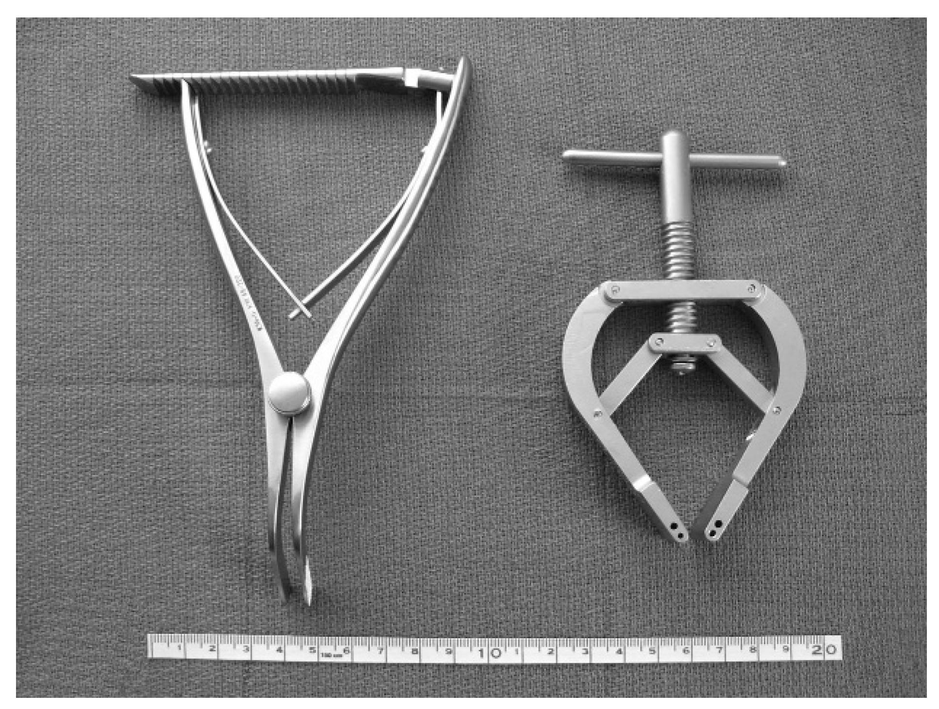
One such commonly used device is the Inge Laminar Spreader (K-Medic, Northvale, New Jersey) (
Fig. 1), which provides joint exposure by the insertion of the blades into the joint. Because the blades of the instrument are placed in the joint, the surgeon must frequently reposition the instrument while performing portions of the key steps in joint preparation for fusion.
The Tarsal Joint Distractor (Orthovation LLC, Sealy, Texas) (
Fig. 1) provides distraction through manual separation of temporary pin fixation placed in adjacent bones, without the insertion of any portion of the instrument into the joint space. Although this may theoretically provide better visualization of the joint surfaces, there have been no reported studies, to our knowledge, comparing the efficacy of these methods. We conducted the present investigation to determine which method of distraction provides the best joint visualization of articular spaces typical of midfoot and rearfoot arthrodesis procedures.
Materials and Methods
A cadaveric surgical model was used to compare the efficacy of the two devices. Pathology samples from autopsies or discarded samples from surgical procedures, such as below-the-knee or above-the-knee amputations, formed the investigational media. Inclusion criteria were intact joints and supporting structures of the foot and ankle. Exclusion criteria were loss of structural integrity of the limb, such as previous midfoot amputation, partial ray resection, or previous arthrodesis. Approval to conduct this study was obtained from the University of Utah Health Sciences Center (Salt Lake City) institutional review board and the Department of Veterans Affairs Research and Development Committee. All of the study procedures were conducted between June 2004 and January 2005.
Six unembalmed cadaver limbs were obtained through the pathology department of the Veterans Affairs Medical Center (Salt Lake City), a tertiary-care facility. The specimens were supplied without identifiable modifiers and labeled only with a numeric code, 1 through 6, representing the chronological order in which the specimen was supplied. On each specimen, a single investigator (S.H.) performed standard surgical incisions and dissection as typically performed for surgical arthrodesis of six joints of the foot. The first metatarsocuneiform, naviculocuneiform, medial intercuneiform, talonavicular, calcaneocuboid, and subtalar joints were sequentially approached and distracted. Each joint was exposed and distracted once using the Inge Laminar Spreader (
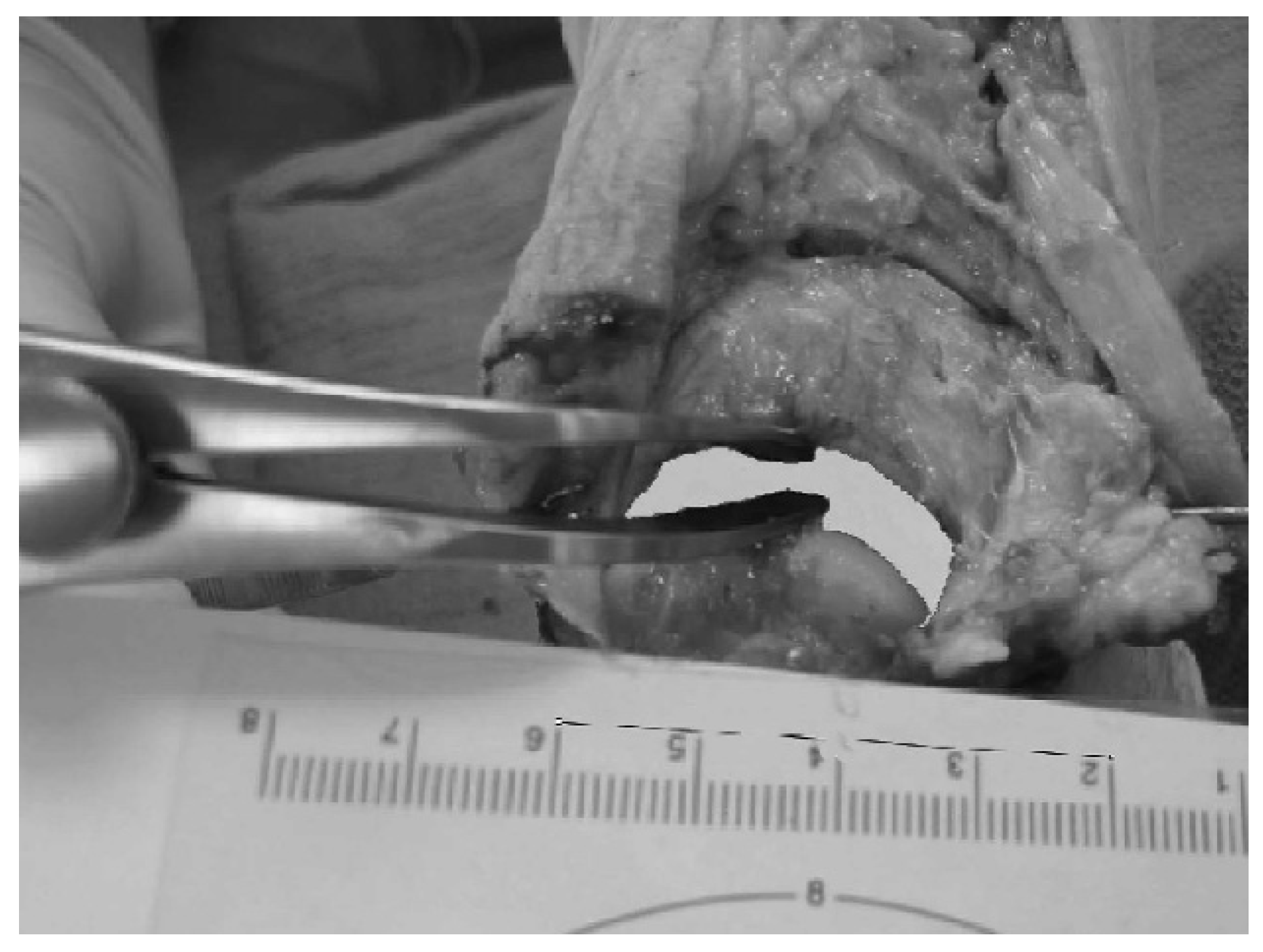
Fig. 2) and once using the Tarsal Joint Distractor (
Fig. 3).
Distraction of any given joint was performed using both devices before proceeding to the next joint. In three feet, the Inge Laminar Spreader was used first to distract all six joints. In the other three feet, the Tarsal Joint Distractor was used first. The order of instrument use for a given foot was randomized by computer, as determined by the Experimental Design Generator and Randomizer (John Innes Center, Norwich, England).
Once a given joint was distracted, a calibrated digital photograph of the exposed joint was taken from an angle best representing the surgeon’s view of the articular space. Digital images were analyzed using a computer-software program (Image Measurement version 4.01; Bersoft, Ottawa, Ontario) to calculate the maximum distance between articular surfaces and the total area of articular surfaces exposed while distracted. The maximum distance between articular surfaces was defined as the distance spanning two opposing dorsal edges of articular cartilage. In cases of asymmetrical distraction, this distance was recorded at the widest point of articular separation. In cases of symmetrical distraction, this measurement was recorded at the center of the articulation. The total area of articular surfaces exposed while distracted was defined as the area of exposed articular space visualized dorsally when the joint was being distracted. Exposed articular cartilage and visualized distracted plantar space at the deep aspect of the joint were included. Portions of the joint space obscured by instrumentation covering articular surfaces were excluded.
The limits of the joint space were defined distally by the dorsal limit of the articular cartilage of the distal bone forming a given joint and proximally by the dorsal limit of the articular cartilage of the proximal bone forming a given joint. The medial limits of joint spaces were defined by a contiguous straight line drawn between the medial limits of the distal and proximal bones composing the given joints. The lateral limits of joint spaces were defined by a contiguous straight line drawn between the lateral limits of the distal and proximal bones composing the given joints.
Each image was individually calibrated using a computer algorithm that compares a known distance (in this case, a metric ruler was included in the digital image) with pixels. The image-analysis software then calculates distance or area on the basis of calibrated pixel profiles of the digital image (
Fig. 2 and
Fig. 3). Results of measurements were recorded and tabulated.
Statistical analysis was performed using the t test and a computer-software program (SAS version 8.02; SAS Institute Inc, Cary, North Carolina) to discern differences between the two distraction methods. The null hypothesis was that no difference exists between distraction of the joints of the foot using the Inge Laminar Spreader versus the Tarsal Joint Distractor. Statistical significance was defined as P < .05.
Results
Thirty-six joints involving six feet were distracted using each device. When distracting any given joint, sufficient force was applied to maximally distract without causing damage, such as articular collapse, cortical disruption, or soft-tissue attenuation. The limit of applied force was based on a single surgeon’s judgment. There were no cases of soft-tissue or osseous damage noted.
The range of articular exposure was 83.8 to 331.5 mm2 using the Tarsal Joint Distractor and 64.7 to 258.1 mm2 using the Inge Laminar Spreader. Mean area of articular exposure was 178.3 mm2 using the Tarsal Joint Distractor and 116.4 mm2 using the Inge Laminar Spreader. This difference was found to be statistically significant (P = .0001). The range of distance between distracted surfaces was 4.8 to 11.5 mm using the Tarsal Joint Distractor and 2.4 to 9.7 mm using the Inge Laminar Spreader. The mean distance of distraction was 8.1 mm using the Tarsal Joint Distractor and 6.5 mm using the Inge Laminar Spreader. This difference was also statistically significant (P = .0001). An average of 53.1% more exposure and 25.2% more distance between distracted surfaces was achieved using the Tarsal Joint Distractor compared with the Inge Laminar Spreader.
Discussion
Many authors have referred to the necessity of joint visualization when performing arthrodesis of the foot [
2,
6,
12,
17,
19,
20,
21]. However, we did not find any comparative studies of various joint-distraction techniques for this purpose. As a result, we conducted a study comparing two common methods of distraction in a manner that could be objectively analyzed.
These results demonstrate that the Tarsal Joint Distractor provides substantially more articular exposure than the Inge Laminar Spreader. Although the Tarsal Joint Distractor produced greater distances between distracted surfaces than the Inge Laminar Spreader, the difference between the distraction methods was even more pronounced when considering area of articular exposure. The increased difference in area of exposure can be partially explained by the way the two devices facilitate distraction. The Inge Laminar Spreader is inserted into the joint, whereas the Tarsal Joint Distractor is not. Thus a proportion of the articular surfaces was obscured by the Inge Laminar Spreader instrument blades, reducing the area that could be visualized.
During this study, we noted that the Inge Laminar Spreader could be placed in the joint with rapid distraction because no additional instrumentation was required. On the other hand, the Tarsal Joint Distractor requires the placement of two Kirschner wires to facilitate distraction. Thus the Inge Laminar Spreader may provide more rapid distraction than the Tarsal Joint Distractor in some cases. However, the Inge Laminar Spreader was repeatedly noted to fall out of position, requiring replacement and repositioning. The Kirschner wires used with the Tarsal Joint Distractor help to secure and stabilize the instrument, which was never noted to become unstable or shift position.
On the basis of these findings, we believe that there probably are uses for both methods of distraction. For short procedures requiring limited visualization, the Inge Laminar Spreader may be more efficient because there is rapid distraction and no need for additional instrumentation. In cases involving more extensive visualization, the Tarsal Joint Distractor may be more efficient because the device is stable and will not accidentally dislodge. In addition, there is no need to reposition the instrument once placed to visualize all surfaces in the joint.
Appropriate visualization of a particular joint can set an overall tone in an arthrodesis procedure. The joints of the foot and ankle present a unique set of anatomical dynamics that cannot easily be adapted to with more traditional existing instruments, thus forcing the surgeon to become creative regarding approach and technique. This dilemma can often lead to a less-than-optimal setting for what is usually an already difficult procedure. Because distraction is a key element of any tarsal arthrodesis, the foot and ankle surgeon should carefully consider the method used to obtain it.
An advantage of this study is that clear objective data were used to compare two joint distraction and visualization methods, with statistically significant results. A limitation of this study is the small sample size, which increases the odds of a type II error. Another possible limitation is that the limit of applied force was based on a single surgeon’s judgment, which may have introduced observer bias.
Conclusion
The Tarsal Joint Distractor provides significantly more distance between distracted joint surfaces and better visualization of articular spaces typical of midfoot and rearfoot arthrodesis procedures than the Inge Laminar Spreader. Theoretically, increased exposure should help decrease surgery time and the rates of nonunion during these procedures; additional prospective investigation is warranted.