Review

Energy Harvesting from Fluid Flow Using Piezoelectric Materials: A Review

1
Department of Chemical and Energy Engineering, Pak-Austria Fachhochschule: Institute of Applied Sciences and Technology, Mang, Haripur 22621, Pakistan
2
Sino-Pak Center for Artificial Intelligence, Pak-Austria Fachhochschule: Institute of Applied Sciences and Technology, Mang, Haripur 22621, Pakistan
3
Department of Mechanical Engineering, Faculty of Engineering, Alexandria University, Alexandria 21544, Egypt
4
International Institute of Urban Systems Engineering (IIUSE), Southeast University, Nanjing 210096, China
*
Authors to whom correspondence should be addressed.
Energies 2022, 15(19), 7424; https://doi.org/10.3390/en15197424
Submission received: 21 August 2022 / Revised: 25 September 2022 / Accepted: 6 October 2022 / Published: 10 October 2022

Abstract

:
Energy harvesting from piezoelectric materials is quite common and has been studied for the past few decades, but, recently, there have been a lot of new advancements in harnessing electrical energy via piezoelectric materials. In this regard, several studies were carried out in electrochemistry and fluid flow. Furthermore, consideration of productive and valuable resources is important to meet the needs of power generation. For this purpose, energy harvesting from fluids such as wind and water is significant and must be implemented on a large scale. So, developing self-powering devices can resolve the problem like that, and piezoelectric materials are gaining interest day by day because these materials help in energy generation. This review paper discusses different techniques for harnessing energy from fluid flows using piezoelectric materials. In addition, various vibration-based energy-harvesting mechanisms for improving the efficiency of piezoelectric energy harvesters have also been investigated and their opportunities and challenges identified.

1. Introduction

In recent years, energy storage and associated power supplies have hampered the development of energy-harvesting systems. There is a lot of vibration energy in the environment, and it can be captured using a variety of techniques, the most common of which are piezoelectric and electromagnetic methods, as shown in Figure 1. A vast number of processes and strategies were studied and manufactured to make use of new energy. Creating electrical energy has grown more significant in recent decades as one of the most often-used energy carriers. Higher power consumption from electronics has accompanied improved computer performance, which, in the case of CMOS technology, combines a stable trend in processing speed with a power increase. The increased power requirements of gadgets have resulted in shorter battery life and lower device utility. To enhance the gadget’s life and minimize the size of the circuitry, researchers are looking at methods for drawing electrical energy from the ambient energy in the vicinity of the device.
Moreover, providing such micro electric components with electricity generated by the combustion of fossil fuels wastes energy and pollutes the environment. As a result, harnessing renewable and sustainable energy from the environment is increasingly popular in the worldwide energy business [2,3,4]. Researchers have focused on obtaining energy from natural sources to replace or prolong the life of batteries. The life of electronics can be increased by energy harvesting, especially those that are unreachable or costly to maintain, such as remote detecting nodes, inserted health sensors, medicinal equipment [5,6], and large-scale sensor networks [7,8,9].
Chemical batteries power many portable electronic apparatuses, such as actuators, sensors, and other observing devices. Replacement batteries can be costly, particularly if the equipment or device is continually turned on or if many battery cells must be changed quickly. VBEHs have proven to be an effective battery solution for reducing portable-device power consumption [10,11]. Mechanical energy is nearly everywhere compared to other energy sources, yet the frequency and mechanical vibration ranges in the natural environment are continually changing [12,13]. When mechanical pressures such as human movement, acoustic signals, airflow, or mechanical vibrations interact with piezoelectric devices, an electric current is generated that regulates the limited electrons. An electrical potential develops in the polar region when piezoelectric materials are pressed. When an electric field is given to the medium, mechanical stress is produced. Ceramics, crystals, thin/thick films, composites, polymers, polar glass, and other materials can be used to make piezoelectric devices [14]. Transducers [15,16,17,18,19], sensors [20,21,22,23,24], and energy harvesting [25,26] are only a few of the uses for piezoelectric materials. Energy harvesting is converting ambient energy (mechanical, solar, thermal, wind, fluid motion, etc.) into electrical energy using a particular material or transmission technique. There are several energy-collecting technologies here in the marketplace within each energy-collecting conversion process. Solar energy is converted to electricity by photovoltaics (solar panels) [27,28,29,30,31,32], temperature differentials are converted to electricity by thermoelectric (thermoelectric generators) [33,34,35,36,37], and the mechanical vibration energy is converted to electricity by electromechanical transducers (piezoelectric, electrostatic generators) [38,39,40,41]. Because of the rapidly developing social globalization, humanity demands novel technology to improve the quality of life. We are surrounded by a plethora of innovative technological devices powered by piezoelectric energy harvesters, notably flexible smart sensors. These devices are capable of communicating wirelessly with one another, as well as with the human body. The internet of things (IoT) and virtual reality (VR) technologies enable users to operate smart sensors for controlling electrical equipment, as well as for monitoring environmental conditions and people’s physical health [42,43,44]. The development of micro- and nanoelectronics technology depends on piezoelectric materials.
The materials’ piezoelectric properties are strongly influenced by the degree of polarization brought on by the poling process [45]. For example, the piezoelectric coefficient of PZT, the most frequent piezoelectric material, is around double that of d31. The generated voltage for the 33-mode energy harvester is projected to be bigger than that of the 31-mode equipment if both modes have the same design specifications. Furthermore, the voltage generated by the 31-mode and 33-mode devices is proportional to the distance between the electrode fingers and the top and bottom electrodes. Because the PZT layer is generally relatively thin, the electrode distance in the 31-mode is shorter than that in the 33-mode. As a result, the 33-mode energy harvester provides greater voltage output, making the 31-mode device preferable for enhanced current production. Kim et al. conducted a similar study for MEMS PZT cantilevers based on the 31-mode and the 33-mode; Lee et al. found that the 31-mode performed better than the 33-mode in the case of the output power provided by the product of voltage and current. They concluded they could get more voltage and power out of the 33-mode device by improving the IDE architecture [46,47,48]. A material with a high Young’s modulus will distort comparatively less when crushed or stretched. As a result, when subjected to a tensile or compressive force, a material with a lower Young’s modulus will deform more and be more flexible and stretchable. In contrast, inorganic compounds such as SiO2 and ZnO are commonly used to modify Young’s modulus of piezoelectric composite materials. Composites with varying modulus requirements can be made by varying the concentration of SiO2 or ZnO [49,50]. Kit et al. presented an analogous investigation of a hybrid piezoelectric nanogenerator based on a PVDF-BaTiO3 composite. Young’s modulus gradually increases with increasing BaTiO3 concentrations, peaking at 10% wt of BaTiO3 when the piezoelectric constant is greatest, suggesting that Young’s modulus is critical for piezoelectric power production [51,52]. Soft polymers with a low Young’s modulus (Y) and low Poisson’s ratio (σ) are commonly used as passive materials because they set fewer constraints on piezoelectric vibrations. As a result, piezo composites with considerable electromechanical coupling are produced. Smith further offered a detailed description of how Young’s modulus and Poisson’s ratio affect composite performance [53,54].
Piezoelectric materials are often utilized in precision motion because of their particular benefits such as quick reaction, high displacement resolution, high stiffness, high actuation force, and minimal heat generation [55,56]. Piezoelectric transduction is the most advanced ambient-energy harvesting technology, and it has found applications in a wide range of industries, including construction, transportation, wireless electronics, microelectromechanical systems, the internet of things (IoT), wearable and implantable biomedical devices, and more [57,58].
Piezoelectric devices are particularly successful in absorbing vibrational energy compared to other energy harvesters since they are simple and lightweight. Piezoelectric equipment or gadgets for accumulating power in fluid fluxes, including water and wind, are critical because of their real-world potential. Furthermore, the fluid flow in the channel and pipeline has the potential to generate considerable amounts of electrical energy. Ocean-wave-motion energy harvesting is being researched as an alternate form of electricity generation. By collecting energy from the motion of ocean waves, the piezoelectric wave energy harvester might offer electrical output for low-power electric applications. Since most piezoelectric energy harvesting systems operate on the microwatt to milliwatt scale, they are perfect for small electronics, including embedded electronics, implanted biomedical devices, wireless sensor nodes, and gadgets. Devices harvesting piezoelectric energy can provide a constant, self-sufficient power source that does not require upkeep or replacement. The autonomous functioning enables cost savings on battery replacement compared to conventional energy sources like batteries. Electronic equipment may also be incorporated into structures or remote regions because of the self-contained power supply. Because of recent improvements in low-power electronics, piezoelectric energy harvesting sparked the scientific community’s interest in the previous decade (e.g., wireless sensors and microelectronics) [59]. This study aims to obtain a detailed overview of piezoelectric energy harvesting from wind and water flows.

2. Energy Harvesting from Fluid Flow

Power and electricity generation from piezoelectric materials has been studied for the last few decades [60]. To improve energy harvesting, different techniques have been reviewed. Piezoelectric devices are most broadly used for their simplicity and for being lightweight [61]. In energy harvesting, the energy production from fluid movement is essential. The mechanical energy of fluids is transformed into electrical energy through piezoelectric materials. Different piezoelectric materials can operate and accumulate this energy directly [62]. High-density kinetic energy is relatively available in flowing media, so the K.E of fluids can provide an opportunity to be the power source of electronic devices. Piezoelectric transducers are widely used to transform fluid kinetic energy into valuable electrical energy. Due to the importance of fluid movement in daily life, such as wind and water, energy harvesting from these sources is essential. Energy harnessing from fluid flow has a prominent probability in channels and pipelines [63,64]. Below, the energy harvesting from water and wind is discussed.

2.1. Wind Flow

Renewable and green energy resources are significant provocations we face nowadays. Vibrations very commonly produce electrical energy by using piezoelectric transducers [65]. Within the energy sources, wind is the encouraging source that is massively used on a large scale for energy production, but less attention is paid on a small scale [66]. Wind energy is inextinguishable and exists almost everywhere in the surroundings. Wind helps in alternative power supplies such as self-driven or automatic wireless sensor networks (WSNs) that need sophisticated monitoring software. Maximizing wind energy usage can generate more power and, hence, reduce the energy crisis. Windmills and wind turbines are commonly used for power generation. The boundary-layer effect and physical hindrances like trees, buildings, and smooth surfaces cause a correspondingly low speed of wind near the surface and act as limitations of energy harvesting [67,68]. In [69], the power generation from wind is illustrated as the impact force generated on the piezo film when power-carrying wind strikes it. An induced electric charge is produced when the wind force generates stress waves in piezo film and a resulting strain in the piezoelectric components. Furthermore, this rectified electric current can be stored in the capacitor, and the stress that produces the current is time dependent.
P w i n d S = 1 2   ρ a i r ν 3
where ρ a i r is the density of air which is approximately equal to 1.225 kg/m3 at room temperature. At wind speed ν, suppose that the flow is laminar [69].
Some challenges were encountered while recording the wind energy on a micro-power scale for generating sensor nodes: (i) in the region with shunted speed and periodic wind patterns, sensor nodes can be distributed; (ii) sometimes, wind energy harvesters are required to be utilized at a tiny cut-in wind speed (e.g., lower than 2 m/s); and (iii) the voltage level required by electronic devices so that from 1 to 3 V should be delivered by low-speed wind power energy harvesters [70]. The above-indicated challenges can be addressed by the small voltage and maximized power density vibrational frequencies of a piezoelectric energy harvester rather than the low voltage and speed of electromagnetic energy harvesters [71,72,73]. There are several ways by which energy can be harvested from wind, including windmills and wind-turbine-style harvesters, flutter-style harvesters, vortex-induced vibrations, and galloping.

2.1.1. Windmills and Wind-Turbine-Style Harvesters

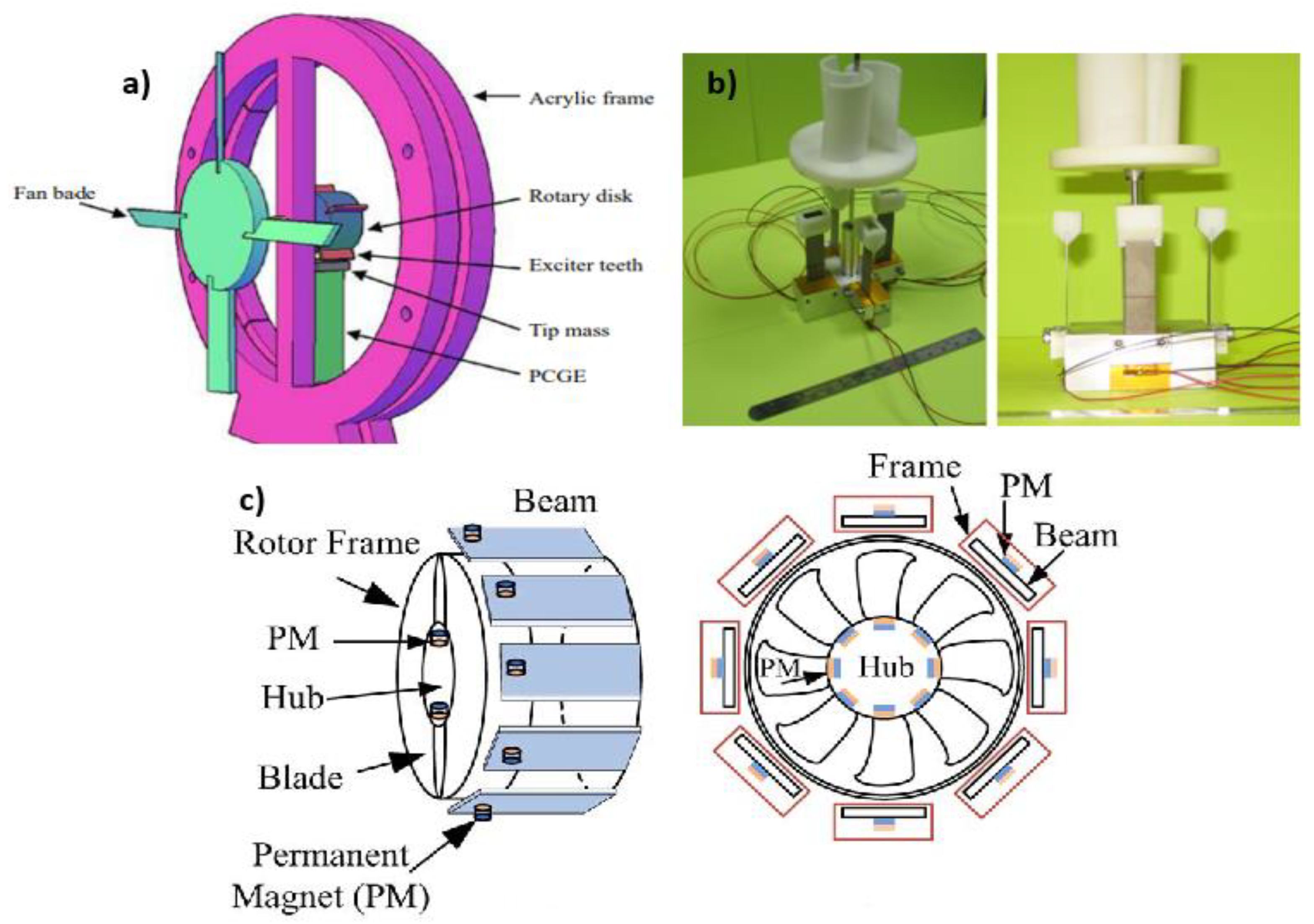
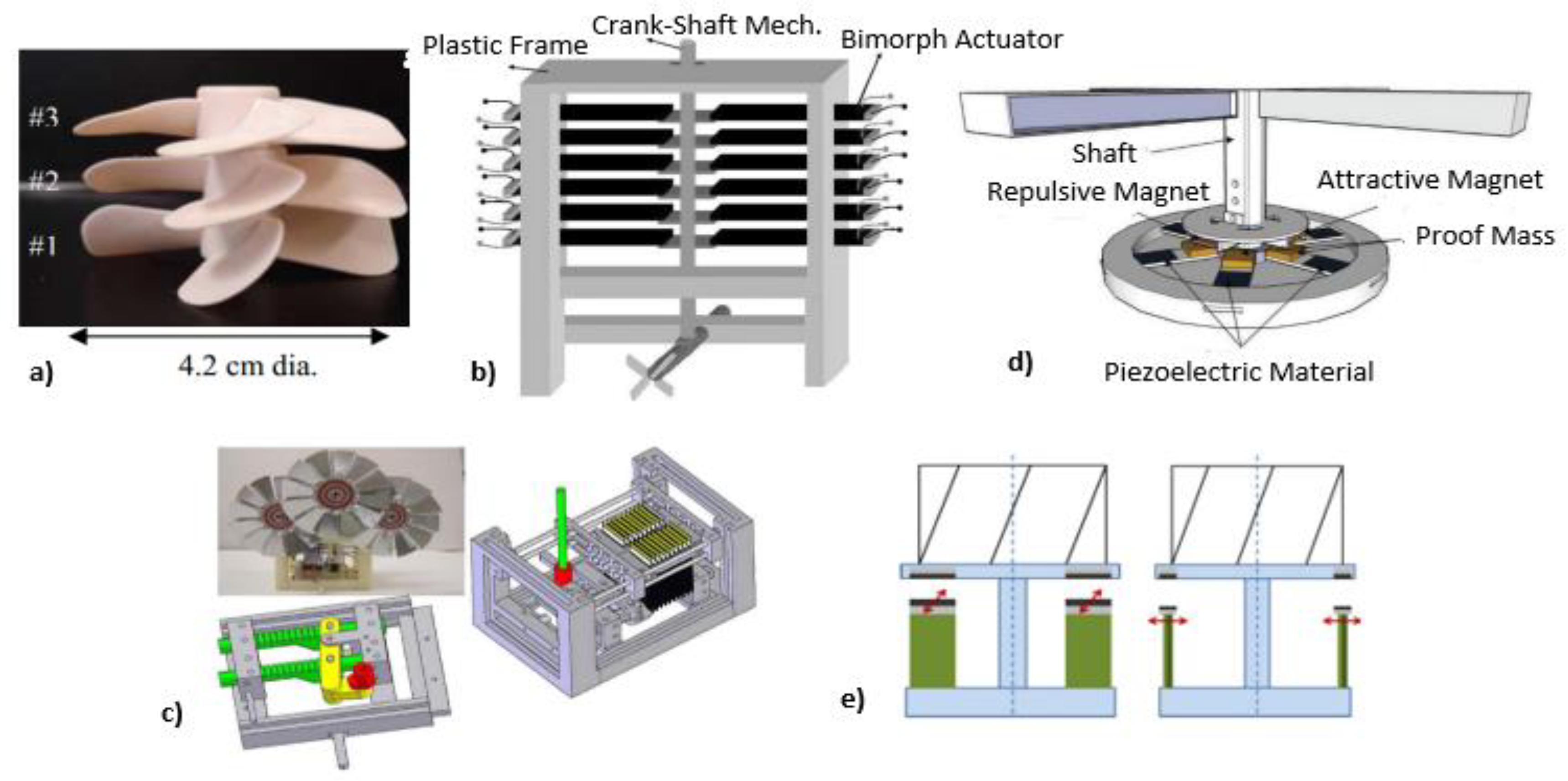
Because of wind availability and its continuous mechanical energy, harvesting energy from wind seems more attractive than from many other sources. Tien and Goo proposed a single PZT composite cantilever windmill harvester concept in 2010 [74]. A standard fan with exciter teeth was attached to the turbine’s shaft to gather energy. A different harvester model was built in a wind tunnel with several bimorphs installed. Yang et al. [75] also presented a novel windmill harvester design with a rotating fan polygonal arrangement. It consists of 12 piezoelectric bimorphs and 3 steel balls inside the polygon. As shown in Figure 2, power will be produced when the wind rotates the windmill, resulting in the piezoelectric energy harvesters being stuck with the steel balls.
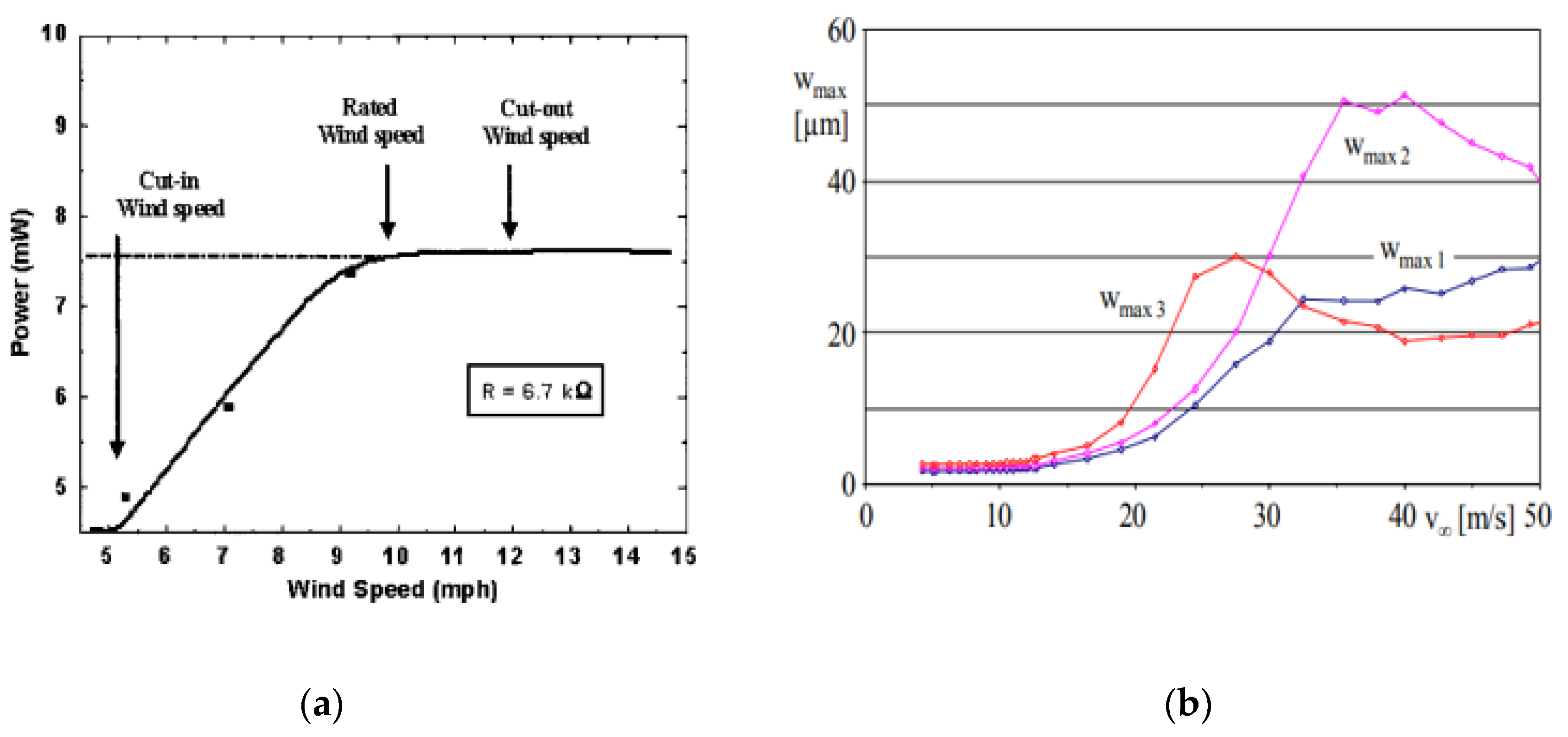
Power generation by centimeter-scale windmills was inspected by Rancourt et al. [76]. An electromagnetic transduction mechanism was used to produce power. Three propellers with a diameter of 4.2 cm and four blades having different pitch angles were tested as prototypes in the wind tunnel. This experiment’s result shows that the “Schmitz theory” of substantial wind turbines applies to the smallest-scale wind turbines, but there is a sharp decline in the power generation at low wind speed because of frictional losses in internal electric resistance and the generator. Similarly, several other studies on windmills and wind turbines were accomplished by Bansal et al. [77], Howey et al. [78], Priya et al. [79], Karami et al. [80], Bressers et al. [81], Chen et al. [82], and numerous others.
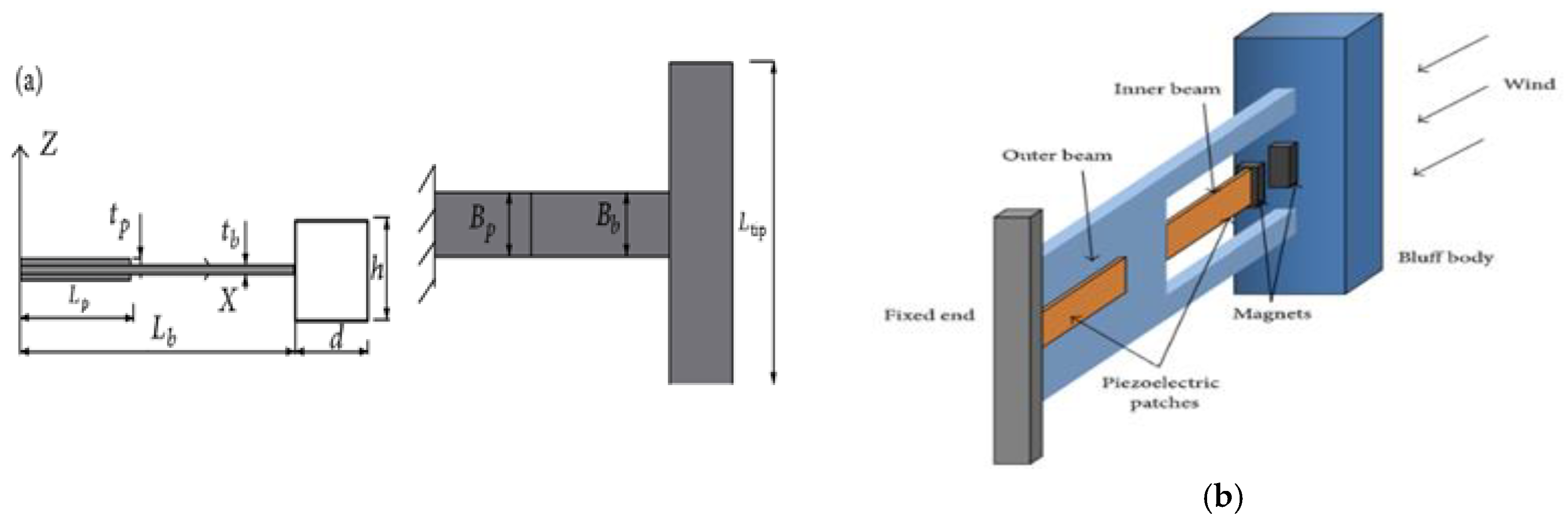
Their studies show that all of them use windmills and turbines having different numbers of bimorphs. Some of them change the alignment of these bimorphs from circular to perpendicular. Compared to circular arrays, they were far easier to fabricate and were space efficient. Still, their drawback was that dissipation of kinetic energy occurs and mechanical damage is caused by the fatigue issues of piezoelectric cantilevers. So, to reduce this issue, a few introduced magnetic interaction by using a magnet at the tips of transducers. High output power, small cut-in wind speed, and a hefty operative range of wind speed can be obtained by both conventional and non-uniform parametric excitation techniques. Figure 3 and Figure 4 show the schematics and graphs of small-scale windmills and wind turbines.

2.1.2. Flutter Style Harvesters

Flutter is an evanescent structure aeroelastic instability in an exceedingly fluid flow. Different kinds of flutters can depend on categorizing their excitement and nourishment mechanisms [84]. Flutter-style harvesters are the second most detailed layouts from energy harvesting to the flowing fluid. Several problems related to windmill-style harvesters using harvesters containing the flutter style were observed, including intricacy, high production, and maintenance price, and small-scale loss of scalability because of both friction and viscous drag [85]. There might be different types by which flutter-style harvesters can be possible, such as model convergence flutter, crossflow flutter, dual cantilever flutter, movement-induced excitation, and extraneously induced excitation.
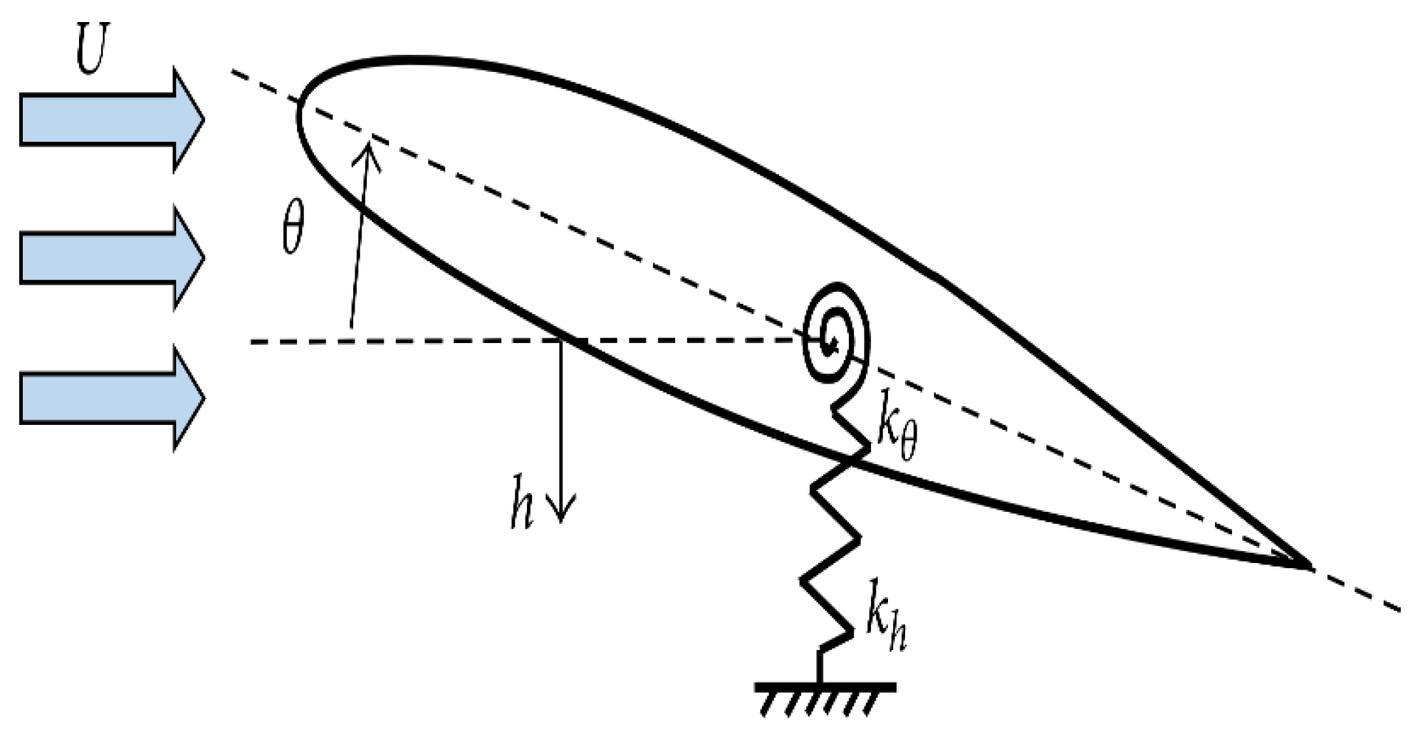
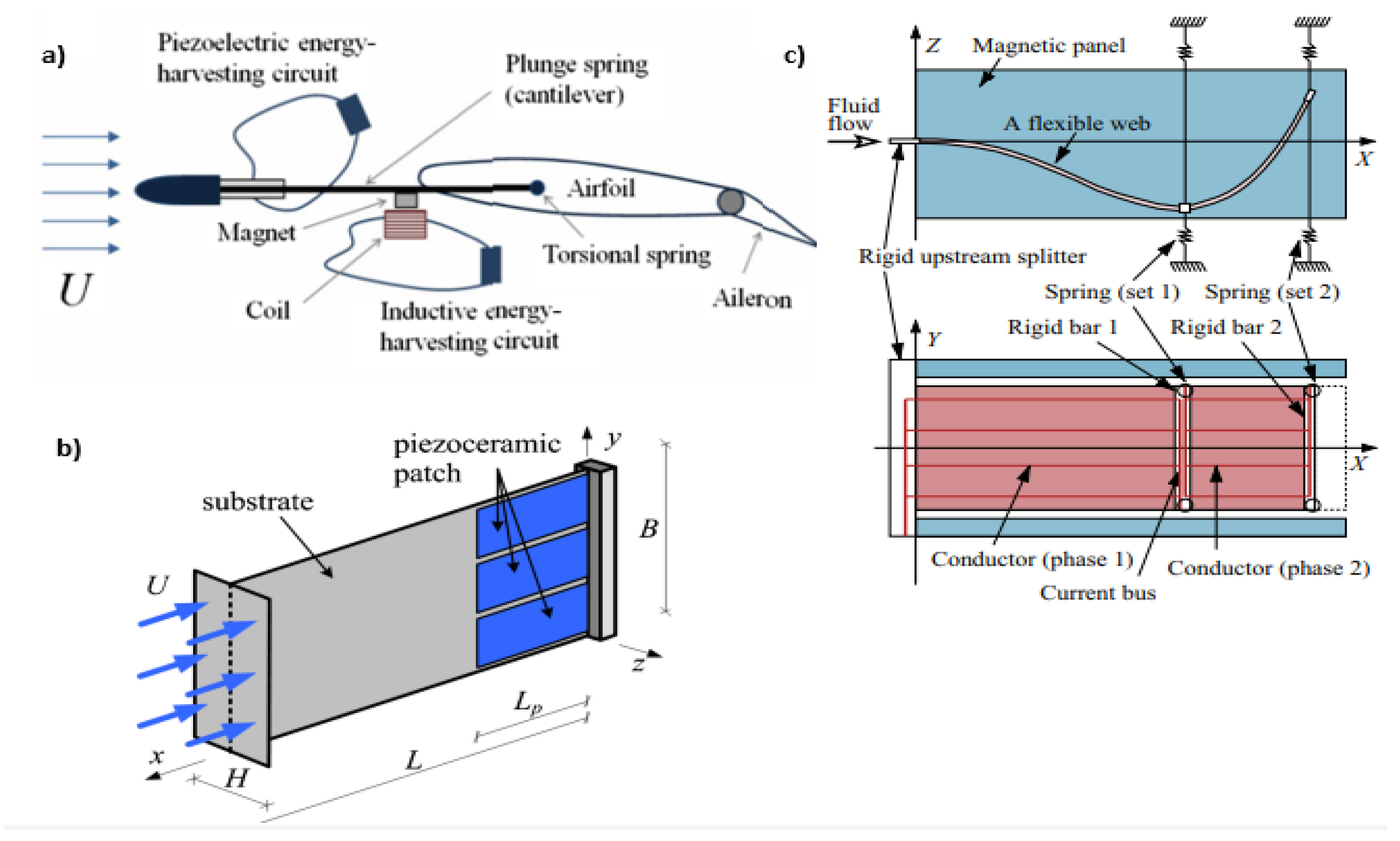
Model convergence flutter is based on airfoil and aeroelastic flutter with coupled pitch-plunge movements. Using the electromagnetic transduction mechanism, Bade, McKinney, and Delauries studied energy harvesting based on airfoils a few decades ago [86]. Bryant and Garcia [87,88] and co-authors are one of the initial companies to study the viability of capturing piezoelectric energy using flapping wings [89,90,91]. Bryant and Garcia [88] initially characterized the wing flutter-based ecological generator in both practical and theoretical wind tunnel findings, and it was then examined in a more comprehensive theoretical modeling manner [91,92]. The impacts of different system architectural aspects on wind velocity were evaluated using experimental and analytical parameter assessments. Reference [92] released research on energy harvesting performance that discovered that peak power intensities and power collection efficiencies of flutter energy harvesting devices emerge at the smallest winds evaluated owing to the device’s restricted sweep range. Resultant load, area of the device, and power accessible in the flow rose as the wind speed maximize, while power density and power separation efficiency declined. Erturk and his colleagues [93,94] were also among the first to investigate the utilization of flow energy in aeroelastic wing hinges. Both theoretical and experimental evidence has shown that optimal demand corresponds to the most incredible chatter rate because of the related maximum damping effect during the power extraction process. Bryant and Garcia’s [95] aerodynamic nonlinearity enables oscillations of the large-amplitude limit cycle that surpass flutter velocities and energy acquisition throughout a broader spectrum of wind speeds. Sousa et al. studied the conceptual and applied benefits of leveraging nonlinearities in the geometry of the piezo aeroelastic energy harvesting technique. Free-play nonlinearity has been studied theoretically and empirically and was proven to lower by 2 m/s in reduced wind speed and maximize electricity production [96]. Dias and colleagues then developed a three-dimensional airfoil-based hybrid aeroelastic harvester with integrated inductive and piezoelectric couplings. The 3DOF architecture has improved harvester productivity by implementing a wider design domain and a broader operational optimization parameter [96]. Boragno et al. also discussed their model convergence-based flutter-based energy harvesting experiment. The investigation was carried out on wing mass, elastic constants, the center of gravity’s position, and the elastomers’ elastic adhesion point that were used to support the two wings to give them bending and torsion rigidity simultaneously. It was concluded that self-sustained oscillation with properly tunned parameters is suitable for energy harvesting, as shown in Figure 5.
Energy harvesters rely on crossflow flutter. The genuine fluttering leaves of a tree subjected to background fluxes inspired this piece. Li and Lipson [97] proposed a device consisting of a polyvinylidene fluoride or polyvinylidene difluoride stock, a plastic pivot, and a three-dimensional polymer “leaf”. The vertical and the horizontal stalk leaf were examined as two alternative layouts with various stalk axis orientations. The highest power density of 615 W was attained with a linked dual-membrane stock of 72 × 16 × 0.41 mm at 8 m/s on a 5 M power, while the highest power density of 2036 W/m3 was attained at 7 m/s on a 30 M force, using a unimorph-limited stem measuring 41 × 8 × 0.205 mm. Like the airfoil-based piezo aeroelastic energy harvester, the upright stalk bends as the leaf experiences paired twisting and torsional movements around the joint, resulting in modal convergence flutter. Piezoelectric materials like PVDF and their copolymers are significant and promising. However, their applications are restricted because of the much-decreased piezoelectricity. As a result, several initiatives to enhance piezoelectricity have been made, broadening the range of applications for it. Other preparation techniques include electrospinning, hot pressing, and solution casting. Processes such as stretching, adding fillers, heat treatment, poling, and nanofiller alignment by electric field/magnetic field have been developed, and the impact of the parameters has been examined to enhance the development of piezoelectric β-phase and the α-to-β phase transition. However, since it is still unclear how crystallinity arises, further research is required [98]. Different leaf shapes, leaf areas, short, long, and narrow-short stalk scales, monolayer, adherent dual-layer, and air gaps dual-layer PVDF arrangements were assessed and contrasted. The leaf’s equilateral triangle, square, and circular forms showed equivalent and maximum power, and the cut-in wind speed rose with the performance of the area of the leaf [99]. It has a parallel-flow asymmetric structure in which a torsional motion of the stalk around axis x was generated by the distance between the stalk and leaf axes. It is an energy extractor dependent on modal convergence flutter; however, because of Li and Lipson’s and Li’s constructs’ similarities, this part of the crossflow flutter contains its recommendations. Because the PVDF functioned in part of the d32 mode, wherein has a less piezoelectric transformation rate, it was determined that electrical d32 power from bending in a linear flow arrangement served solely as an auxiliary small-value gain as a result of folding. Although substantially less than a crossflow equivalent harvester, the production was comparable to a parallel-flow flapping-leaf harvester. De Marqui Jr. et al. also conducted studies about energy gathering from crossflow flutter [100]. For divided electrodes, torsional movements of the linked modes became very considerable, which was related with enhanced broadband productivity and greater flutter speed.
Hobeck et al. proposed another study on a novel type of flutter called a “dual-cantilever flutter”. Two cantilevers of 14.6 × 2.54 × 0.0254   cm 3 were exposed to wind flow to experience the large amplitude and persistent vibration in the experimental setup of a wind tunnel. The highest power of 0.967 mW was obtained at 13 m/s. If the distance is small, between 0.25 cm and 1 cm, the cantilever produces enough power in the range of 3 m/s to 15 m/s. This determined that the “dual-cantilever flutter” is responsible for strong energy-scavenging methods for nonlinear flowing fluid [101].
Movement-induced excitation (MIE) is an immersed-shape self-excited flutter followed by twisting fragility at resonance, as shown in Figure 6. Negative damping and structural deformation through divergence occur at critical flutter speed. The seminal work demonstrates that self-generated MIE flutter and self-supported flutter. The seminal work was further illustrated in [102,103]. Critical flutter speed, the relation of flutter frequency, and a two-dimensional complaint beam in viscous flow were explained based on scaling laws, as shown below in the equation.
ω   ~   ρ f U 2 ρ s h   L
U c   ~   Y h 3 ρ f   L 3
where ω is flutter frequency, U c is the critical flutter speed, ρ f is the density of the fluid, and ρ s is the density of the beam. Similarly, U c is the flow speed, h is the thickness of the beam, L is the beam length, and Y is the elastic modulus of the beam. Recently, experimental verification on scalable rules for rectangular, tri-directional beams was followed in [104].
µ = ρ s   h ρ f   L
where µ is the mass ratio, the above Equation (1) shows that the fraction of the non-dimensional weight is enormous. For an adequately minor mass ratio, dense effect and added mass are responsible for controlling the beam flutter motions compared to the estimated model displacement [105].

2.1.3. Vortex Induces Vibrations

Vortex-induced vibration (VIV) was priorly investigated in water flow rather than wind flow. When bluff bodies are subjected to an external force resulting in periodic abnormalities in the flow, vortex-induced vibration (VIV) emerges. The oscillations in the underwater cylinder are an excellent illustration of vortex-induced vibration. Because of its considerable curvature, this limit layer might segregate from the body at numerous locations. The pressure distribution along the surface is then changed by the generation of vortices [106]. Akaydin et al. [107] suggested a novel self-excited vortex-induced vibrational energy harvester to boost output power. Unlike in earlier occurrences, PZT was used to cover the end area of the cylinder, which was an aluminum cantilever’s free end connected. The aeroelastic efficiency was raised from 0.032% to 2.8% compared to the prior design. The finding was that the altered arrangement of the cylinder connection to the cantilever end and the substitution of PZT for PVDF considerably improved the power extraction. Due to vortex shedding, regular oscillations are generated in the path perpendicular to the flowing wind.
Weinstein et al. [108] developed an energy scavenger with tunable abilities for resonance to overcome the short operating range of VIV-based harvesters and presented a resonance-tuning-capable energy harvester. An aerodynamic fin was used to affix the piezoelectric cantilever to the head of a cylinder body. The resonant frequencies of the harvester might be fine-tuned by directly altering the mass locations. Weinstein et al. [108] proposed an energy-harvesting device ranging from 2 to 5 m/s. Their research was centered on the means of a piezoelectric beam affixed to the tip of a cylinder to capture energy from the VIV phenomena. Gao et al. reported a spherical prolongation to a piezoelectric cantilever (PEC) is used in a wind-energy collecting device. This model was constructed to generate electricity from VIV using a nonlinear distributed 192-parameter model, confirmed by the experimental data of Akaydin et al. Using a flexible piezoelectric beam, Goushcha et al. [109] collected the vibration energy based on the VIV. The topic of fluid flow energy extraction through the VIV of a circular cylinder in a dual-mass configuration was examined by Xu-Xu et al. [110]. Wang with his colleagues [111,112,113] created energy harvesters in the shape of a flow path, which they claimed were operated by a bluff body in the stream producing a vortex and shedding it. The diaphragm is attached to a piezoelectric patch or a magnet and coil for energy transmission. The effects of different bluff body shapes on wind harvesters were studied by Tam Nguyen et al. [114]. A 0.2 mm broad polydimethylsiloxane (PDMS) diaphragm was implanted in the prototype, and a PVDF sheet was bonded up to the flow network’s peak. The prototype measured an average power of 0.59 nW and a 14 mV open-circuit voltage at a wind velocity of 20.7 m/s. Wang et al. [115] utilized computational fluid dynamics modeling to highlight the importance of establishing the area of synchronization for VIV energy harvesting. Lately, the so-called vortex bladeless wind generator has been used in conjunction with VIV to capture wind energy on a big scale.

2.2. Galloping

Various investigations have proven the likelihood of extracting meaningful energy from the surrounding flow for the significant galloping vibration. The studies of mainly transverse and torsional energy collection during galloping are discussed. The aeroelastic instability phenomena of transverse galloping have only recently been used to get vibrations inside the structure for energy gathering. Galloping, in comparison to VIV, has the characteristics of enormous oscillation amplitude and the capability to oscillate in an unbounded range of wind speeds, which is desirable for energy harnessing [116]. Several research studies have shown transverse galloping energy extraction’s analytical and theoretical feasibility. Barrero-Gil et al. published analytical research to demonstrate the feasibility of cross-country galloping as an energy source. Using a 1DOF model, theoretically, Barrero-Gil et al. looked at the possibility of using galloping to generate energy. There was no particular type of energy harvesting suggested. The aerodynamic force was calculated using a cubic polynomial depending on the quasi-steady hypothesis. Theoretically, a very effective bluff body was determined to have a higher A1 aerodynamic coefficient and A3’s small significance level. The mass-damper parameter must be set to a minimal value for the mechanical damping [117].
Rather than utilizing a polynomial fitting, Sorribes-Palmer and Sanz-Andres [118] extend the research by accumulating the aerodynamics curvature parameter straight-forwardly by investigation records. Sirohi and Mahadik [119] presented a galloping energy harvester with two 161 × 38 × 0.635 mm3 cantilever beams and a prism 251 mm in length linked to the outer end and a 40 mm symmetrical triangular cross-section in every boundary. Directly acquiring from the experiment has eliminated the difficulties involved with polynomial fitting, such as incorrect dynamic reactions caused by erroneous polynomials. Sirohi and Mahadik [120] devised alternative galloping with an energy harvester, such as a D-shaped cross-section coupled to the composite piezoelectric beam. The tip body has a diameter of 30 mm and a length of 235 mm, while the cantilever has a volume of 90 38 0.635 mm3. An axial fan was used to create the wind flow, which had a highly turbulent profile. With a 10.5 mph wind velocity, the power density of 1.14 mW was produced.
Abdelkefi et al. [121,122] examined the topic with an energy harvester of a galloping square cylinder in a theoretical study. They discovered that when the load resistance grew, the commencement of galloping and output electrical power improved, but the displacement was reduced. An ideal load for higher Reynolds provided maximum power output, the maximum beginning of galloping, and minimizing distance simultaneously. According to Yang et al. [123], and Daqaq [124], once all energy harvesters are configured effectively, a bluff body with a squared section generally outperforms D-shaped and equilateral three-sided objects at high wind speeds. Using the Weibull probability density function, wind data were fitted, and Bibo and Daqaq [124,125,126] included actual wind-data figures in the results of energy harvesters that are in motion (PDF). Vicente-Ludlam et al. [127] discovered that by adjusting the output tolerance to loads in the appropriate adjustable, the power and efficiency for each wind-velocity generation productivity might be maintained throughout a broader range of wind speeds, as shown in Figure 7. Putting an impact bump stop onto a galloping harvester was discovered to extend its durability significantly during electromagnetic energy collection by a dual-mass galloping.
Figure 8 below shows that when the speed of flow increases from the critical value, transverse fluctuation becomes the cause to interrupt the bluff body exposed through the airflow, and this phenomenon is known as galloping. There are twin galloping bluff bodies in the wake form of PEH; one is connected to the loose at the beam’s tip, and the other is attached in its front. A primary rule for the front bluff body depends on the certainty that variations are produced in the spacing distances [129,130,131]. Much research has been taking place to investigate the impact of various factors on galloping manufacturing [132,133].
All the methods and techniques of energy harvesting from wind are described in Table 1 below:
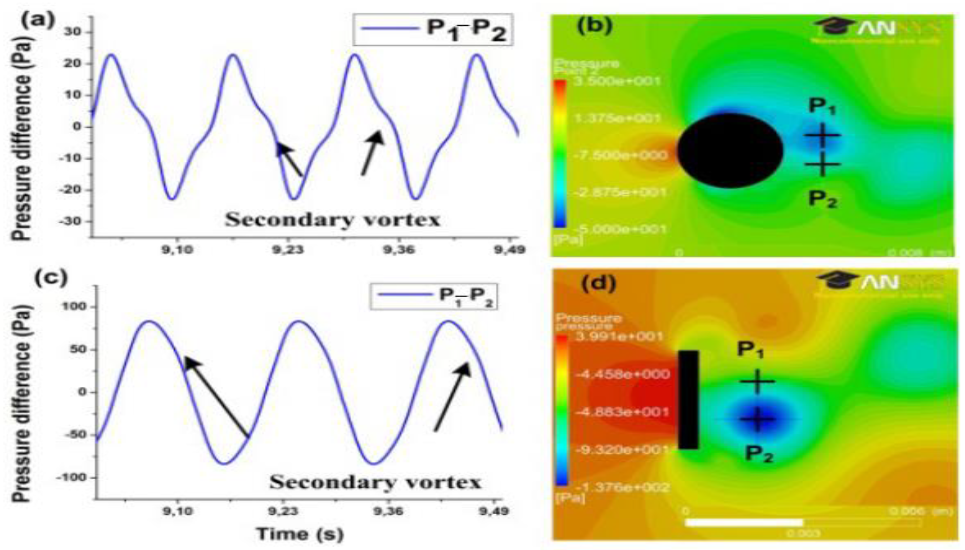
Many bluff body designs were studied to increase the wake flow’s pressure from the vortex. Researchers conducted computational fluid dynamics (CFD) models to understand better vortex formation and how it affects the harvester efficiency. When a half-reversal velocity occurs when the river passes, the bluff body velocity difference occurs because of fluid pulls causing the vortex to form. Viscous shearing between the solid object and the fluid layer generates friction drag. Maximizing the velocity ratio, k, generates an inner kinetic energy reduction throughout the bluff body’s longitudinal distance.
As a result, the length is reduced by using a bluff body with a cuboid form. Because of the steep flow detachment point, the primary edge might move toward the inflow area, increasing vortex pressure. According to CFD simulation results, the vortex pressure in the wake of a cuboid-shaped bluff body reaches 84 Pa at 2 m/s air flow (Figure 9c). This is roughly four times larger than a cylinder-shaped bluff body, as seen in Figure 9a. The simulation’s outcomes indicate the shedding of an additional vortex that flows following the primary vortex (Figure 9a,c). It was supposed to be more dampening, which would result in poor harvester performance [148]. Table 2 shortlists all the techniques that help in energy harvesting in wind flows from piezoelectric devices.

3. Water Flow

Considering that flowing water has a high amount of kinetic energy and sensitivity to environmental situations, sustainable energy from water sources has a great deal of promise. In energy harvesting, energy generation via fluid motions has become an everyday activity. Small-scale energy-collecting devices might be used by installing energy harvesters in the network. As a result, numerous investigations on energy harvesting depending on piezoelectric components’ use in fluid flowing through ducts have also been conducted [165]. For powering various small-scale devices, Lee et al. [166] developed a piezoelectric flow-energy-collecting gadget with a transducer that has a cantilever. The theory and construction have been studied for long-term reliability, quality performance, high accuracy, quick response, low power consumption, small size, and piezoelectric actuator-driven valveless pumps. Drug administration, biological applications, chemical analysis, high precision glue, solder paste, lubrication systems, and electronic chip cooling systems are a few of the many domains where the pump is vitally important. Furthermore, the operating voltage ought to be further decreased since the pump’s control circuit and power supply are more crucial [167]. At a flow rate of 20 L.min−1 and a pressure drop of 165 kPa, the experimental findings showed collected energy of 20 mW. Taylor et al. [168] published the first papers on piezoelectric materials with flowing liquid harvesting in 2001. In a fluid tank, a prototype eel with measurements of 24 cm 7.6 cm 150 m was built and successfully observed. Taylor et al. described a PVDF bimorph emergent in water flow as an energy-collecting eel. Pobering and Schwesinger conducted experiments on bimorph-containing piezoelectric energy harvesters in 2004. Pobering and Schwesinger observed the electricity production of a small piezoelectric cantilever beam exposed to liquid and gas flow in advanced analysis, a computational and practical investigation published in 2009. A PVDF flag may gather up to 32 W m2, whereas a PZT bimorph with measurements of 5 3 0.060 mm3 can produce roughly 7 W. For a flow velocity of 45 ms−1, the stream channel had 0.8 V and 0.1 mW for a structurally non-optimized system [169,170]. Shan et al. investigated water-induced vibration-energy harvesting utilizing a piezoelectric constructed of massive fiber composite and the VIV (MFC). The energy harvester’s design gives descriptive statistics by considering that the experiments demonstrate a power rating of 1.32 mW. A bicylinder VIV PEH was presented by Song et al. [171] to reclaim energy from water movement. The largest amount of energy harvested was recorded to be 21.86 mW. An innovative energy harvesting technology, including a vertical cylinder, was also investigated by Song et al. [172] and collaborators. This harvester’s total power was 84.49 mW. Figure 10 shows the fluttering flag harvester and piezoelectric sectioned fluttering flag.
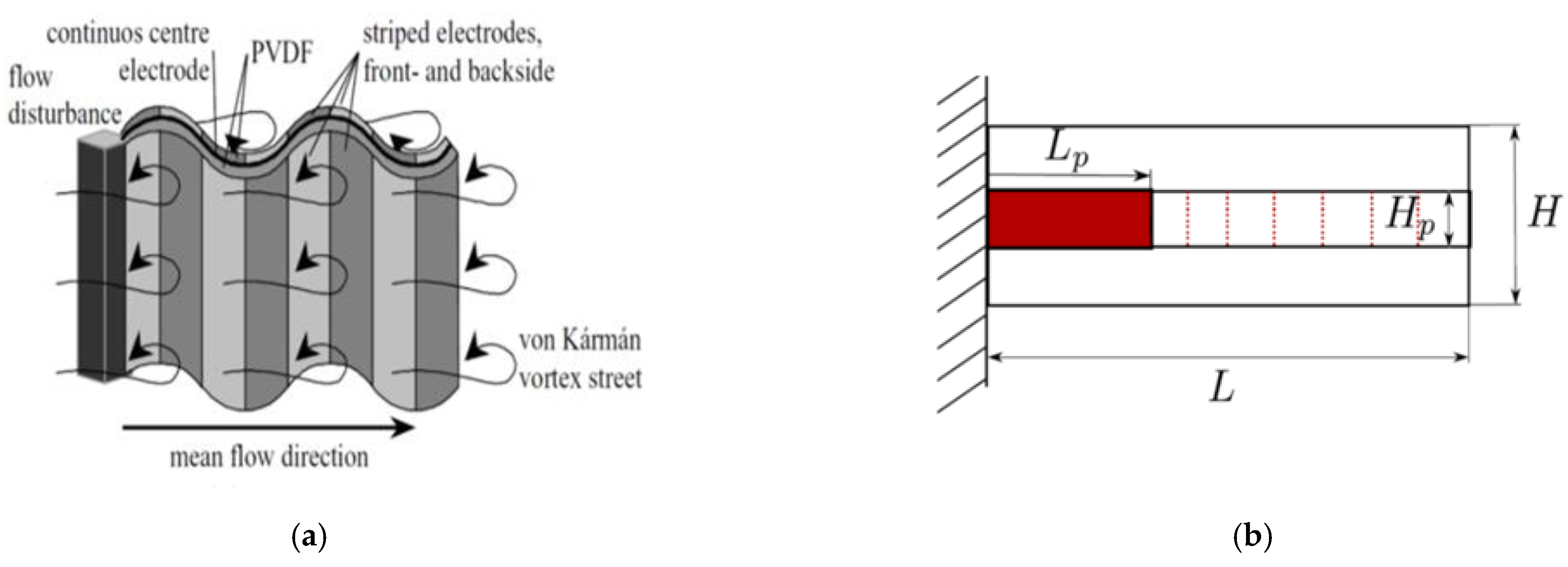
Hassan et al. [173] used a piezoelectric transducer-based model to capture energy transfer from narrow fluid paths. The anticipated output voltage was 0.7 V, although it might be raised following enhancement. The most popular sort of energy is the Karman vortex street-based harvesting mechanism that includes a flexible membrane with PVDF. The VIV was driven to transform kinetic energy into electricity by combining the flow around a piezoelectric cantilever beam linked to a D-shaped bluff body. The motion fluid is an essential part of point-of-care (POC) devices. As a result, micro-pumps have received considerable coverage. The volume change resulting from a bent membrane is used in a few small pumps, such as rotary membrane pumps. Wang and Ko, based on the Karman vortex street, created an intriguing piezo-aerial energy-gathering device. A PVDF was connected to one end of an adjustable diaphragm, and the water was transferred through a pressure chamber incorporated underneath the diaphragm. The force inside the chamber pressed the diaphragm upward. As a result, the diaphragm oscillations maintained energy in the piezoelectric film. The conclusions exhibited 2.2 V having the highest value and incredibly fast power of 0.2 mW when operating the FE model.
It is important to note that the moving fluid is an essential part of the tip-of-cheval apparatus. As a result, the use of micro-pumps has received considerable interest. The loudness fluctuation caused by a displaced layer is the basis for several micro-pumps, including reciprocating membrane pumps [174]. The lead zirconate titanate PZT ceramics and piezoelectric transducers [175] are commonly used to achieve this function. The piezoelectric pump is a micro-pump that works for low-rate flowing fluid. The activity of the micro-pump might be investigated using numerical modeling under the working circumstances. As a result, this method is one of the most effective methods achieving an ideal design for micro-pumps. Exceptional research has been done in this area [176,177].
Stemme created the initial piezoelectric smallest pump without a valve to decrease valve degradation and tiredness by employing components of flow-rectifying reflectors and valves. Ullmann and Fono [178] proposed an energetic method to forecast the piezoelectric pumps’ vigorous behavior. The fluid acceleration in the nozzles was considered in their suggested model, which was built on the kinematic model. Ullmann and Fono [179] developed a model to improve the effectiveness of a valveless piezoelectric pump. The effectiveness of this system was investigated using experimental data on factors such as operating frequency, length, and diameter, as well as the intake and exit of the conducting pipe. Zhang and Wang [180] developed a fuel distribution system using detailed modeling of a piezoelectric nozzle micro-pump. There could be another part in the construction of micro-pumps called the valvular conduit with better volumetric efficiency than the nozzle/diffuser components [181]. Morris and Forster also studied a circular piezoelectric micro-pump actuator [182]. The FE approach was used to find the best metallurgical and mechanical features. A copolymer known as poly(vinylidene fluoride-co-trifluoroethylene) has recently been produced in microfluidics. Xu and Su [183] described a PVDF-TrFE (vinylidene fluoride-co-trifluoroethylene) microfluidic pump. In a separate study, Xia et al. [184] employed a PVDF-TrFE micro-pump with an operator that had an actuation deviation of 80 m in an electric field of 90 V/µm. For the micro nozzle-diffuser pump, the micro-pump was employed as an electromechanical transducer. Pabst et al. [185] suggested a piezoelectric polymer printing method for PVDF-based transducers using just inkjet printing. In Table 3, piezoelectric devices that help in energy harvesting from the liquid fluid are described.
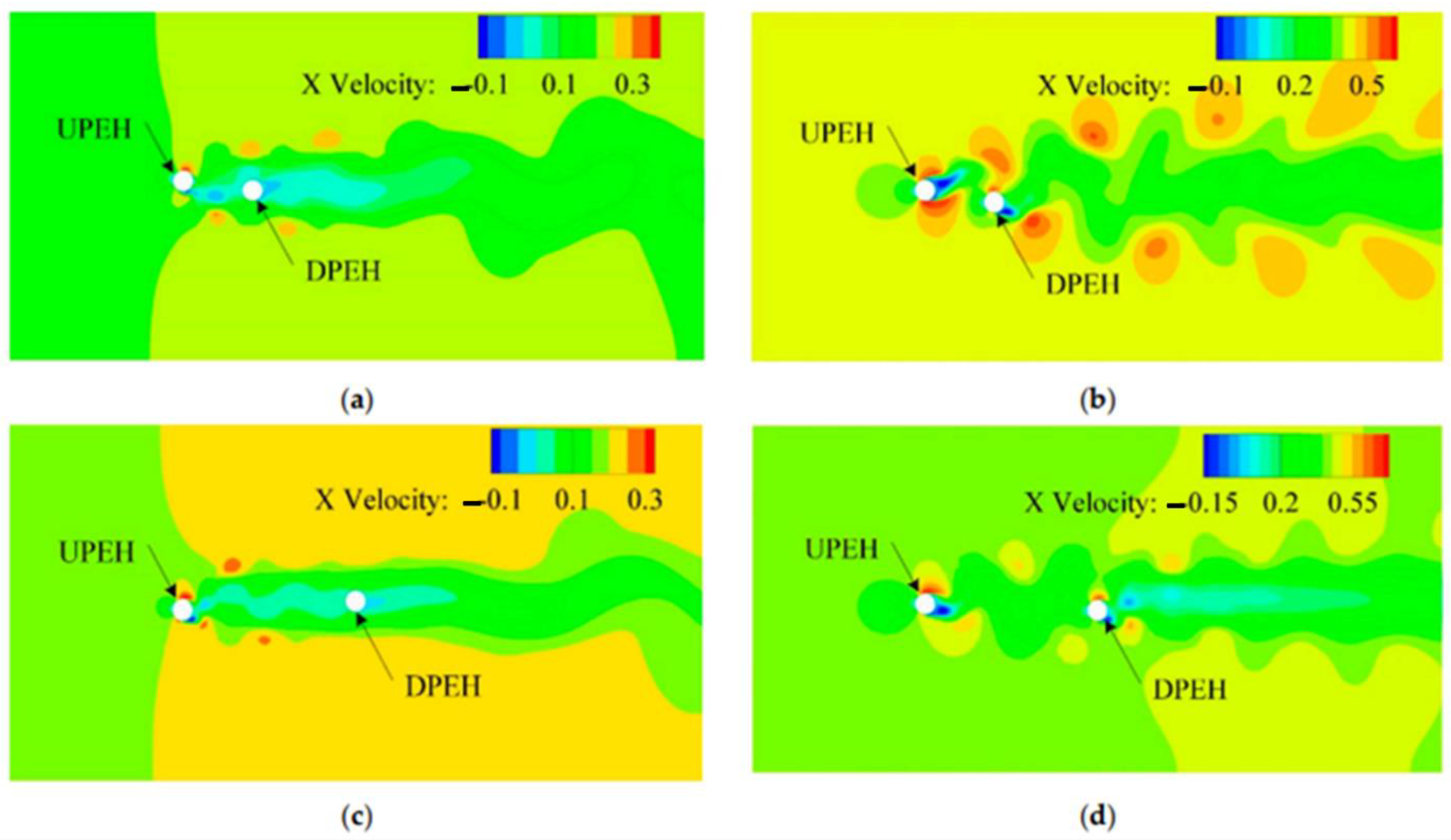
Figure 11 depicts the x-axis fluid velocity field shape with various gap ratios and water velocities. Figure 11a,c show that because the flow velocity is low (U = 0.19 m/s), a mechanism to reduce flow area can occur after the water has flowed through the upstream PEH downstream (cylinder). The lower PEH would be moving at a slow rate area at this time. As a result, the lower PEH’s vibration response and power production capability were poor at reduced water flow. Simultaneously, since there was no feedback from the downstream PEH and it had little impact on the antecedent PEH, the upstream PEH’s vibration response was comparable to a lone PEH in lower-speed flow. The downstream PEH was on the route of the vortex in which the upstream PEH had fallen off when the flow velocity was high (U = 0.41 m/s), and the surrounding vortices that were also on this path were rather powerful, as seen in Figure 11b,d. The vibration reaction and the downstream PEH’s power output efficiency would be considerably enhanced if the vortex was stimulated. Furthermore, as the vortex progressed across the flow field, it dispersed, and its turbulence strength diminished. As the dispersion ratio increased, the vibration sensitivity and capacity to gather energy from the downstream PEH dropped. As the separation ratio increased, the vibration feedback and capacity to gather energy from the downstream PEH dropped [198].
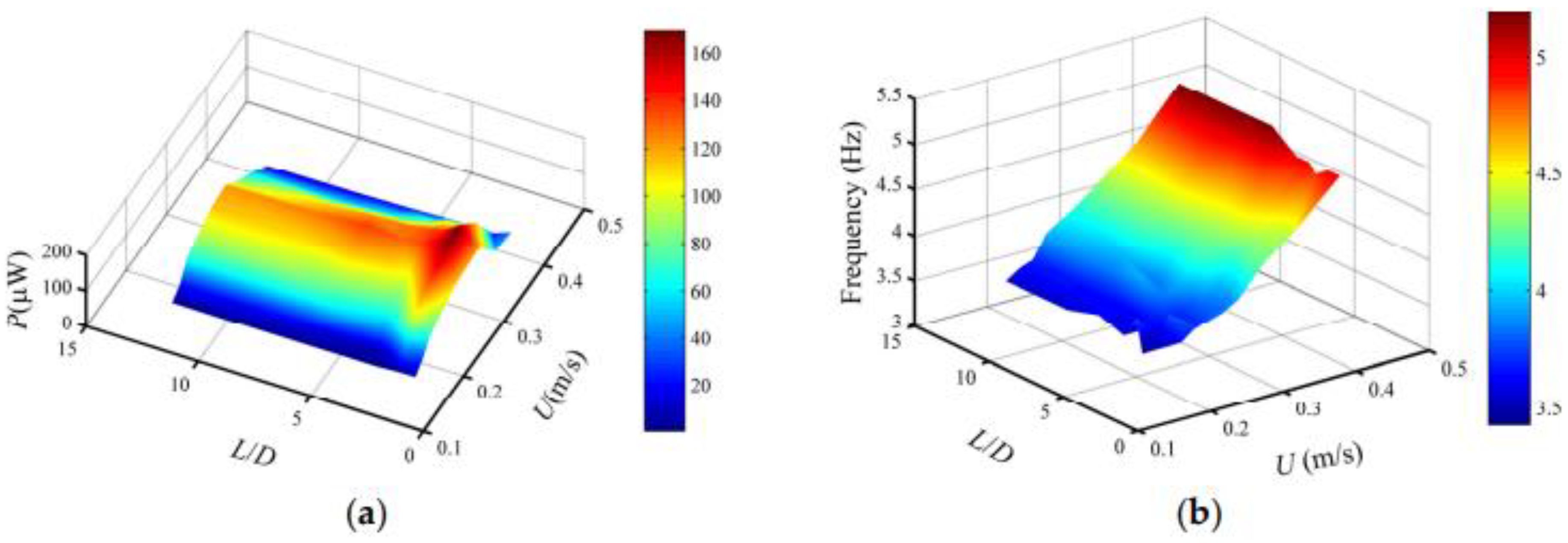
Figure 12a,b demonstrate how output power and vortex-shedding frequency vary because of water velocity and separation ratio.
Figure 12 shows that when the separation rate is reduced in the region (L/D 3.75), the output power differential is particularly substantial in the spacing ratio direction, indicating that the spacing ratio substantially affects the upstream harvester’s efficiency. Due to the difference of the resultant power being nearly equivalent to zero in the dispersion proportion region, the spacing ratio’s influence gets weaker as the separation ratio band increases. The water speed, on either hand, has a substantial effect on the upstream harvester’s efficiency since the generated power differential is forever quite large along the path of the water’s flow. Figure 12b shows that speeding up the water causes the vortex-shedding frequency to rise for a specific separation ratio. The vortex shedding justifies it being relatively steady for a given water velocity as the separation ratio increases. It may be deduced that the vortex-shedding frequency is determined by water speed rather than by the spacing ratio [199].
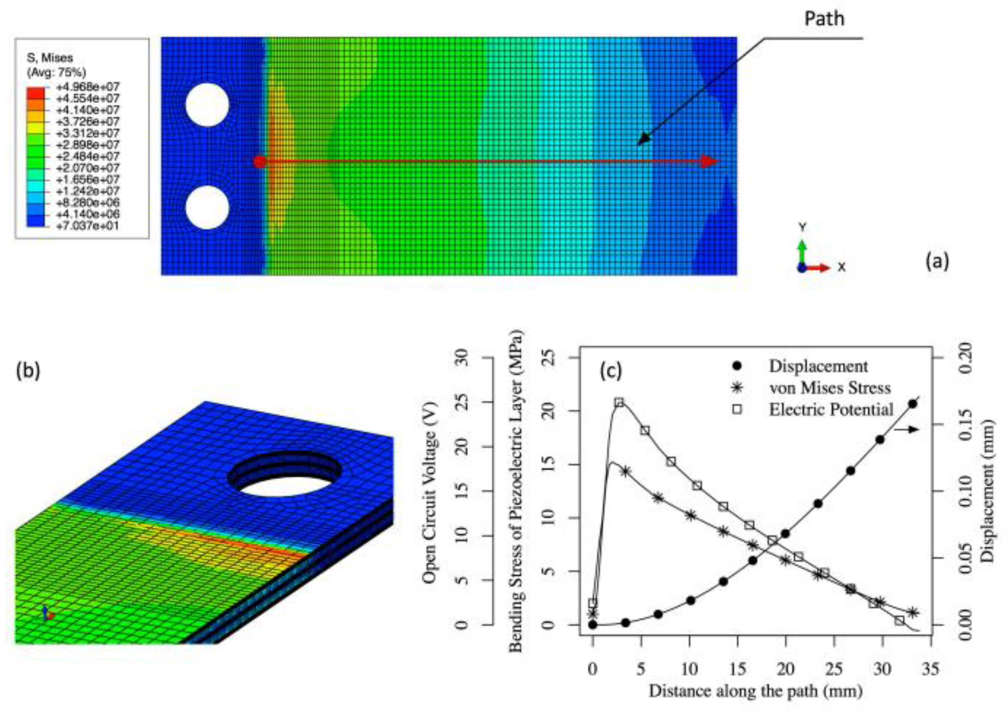
Figure 13a,b illustrate the static analysis findings, which reveal stress concentrations at the armored QP21B’s clamping joint. A force of 1 N is applied to the laser’s point, resulting in a 0.18 mm tip deviation. The layer of stainless steel has the maximum stress-out (50 MPa), which is owing to stainless steel’s greater Young’s modulus than the other layers. The piezoelectric layer’s maximal von Mises stress level is roughly 15 MPa.
Figure 13c shows the piezoelectric layer’s power potential (open circuit voltage), highest curved stress, and head relocation as a function of location along the actuator length, having a 20 V open-circuit voltage at the end deviation of 0.18 mm. P r m s = V L 2   2 R L estimates the 5 mW RMS electrical power supply, supposing the bimorph vibrates at 150 Hz and the fitted 10 kOhm electrical conductivity, R     ω C p 1 ,   V L = 10   V . The rigidity might be approximated over these findings using its description = F δ , and the efficient Young’s modulus of the armored QP21B structure might be computed using formula k e q = Y b ω t 3 4 L 3 ; 205 GPa and 5.55 N/mm, respectively, are the first and second values.
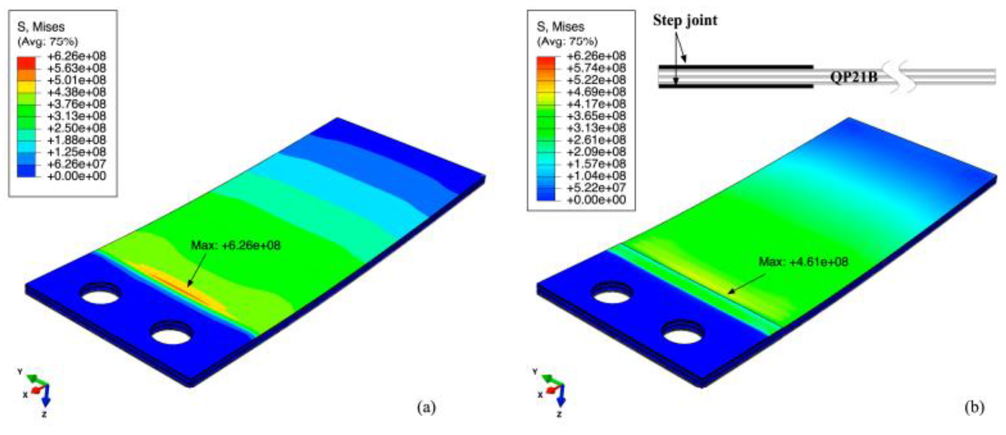
The armored QP21B tip deviation achieves an estimated maximum of 2 mm beneath an unsteady fluid-flow driving force, implying that the calculated adjustable stresses on the configuration are approximately 10 times higher. For instance, the stress on the stainless-steel layer might be 500 MPa, which is over the stress limit of the material. Including a fillet or adhesive contact area that extends along the bimorph’s attaching corner line has been examined as a way to lessen stress application. It is demonstrated that the stepped link-attaching arrangement is easy and efficient in lowering the amounts of stress without compromising the material’s twisting rigidity. The stress-study findings of armored QP21B stepped in the joint (0.0508 mm thick) below a 2 mm displace in the edge are shown in Figure 14. The stress result of an armored QP21B with no stepped junction is also seen under a 2 mm point movement given in the picture for reference. It is worth noting that, as predicted, lengthening and stepping the installation can reduce the stress region at the attached line by 26% [200].
Required information that mapped the beam form was utilized as an alternative method of determining the power output, as well as a first-order estimate of the stress pattern throughout the length of unlike parts of the bimorph actuator’s sections. Even though the approach still has to be refined, this part will go through its specifics and preliminary findings compared to finite element models and empirically observed power output. The cantilever is modeled as constrained using a Euler-Bernoulli beam with attached and unrestricted borderline constraints in this study. This means that bending stresses are more important than shear stresses and that modest strain and shift in the beam compared to the longitudinal distance L of the beam occurs. An extension of the eigenfunctions of the parameters for the biharmonic operator eigenvalue issue were used to estimate the form of the beam [201]. Table 4 shows the piezoelectric materials in water flow.

4. Piezoelectric Materials in Ocean Wave Harvesting

Ocean-wave energy has indeed been found to be a reliable way to capture energy with a worldwide capacity of 2 TW [202,203,204,205]. In general, the density of ocean-wave energy is higher than other renewable energy resources, ranging from 4 to 30 counts greater than wind energy [206]. As a result, developing an inverter for wave energy is critical in collecting ocean tidal energy. Alternatively, along with its long-term viability, wave power from the ocean can generate electricity. Due to the energy disasters and environmental perturbations, the topic of the economic issue of wave-energy inventors related to their uses is of significant relevance today [207].
In comparison to wind energy, wave-energy conversion (WEC) devices are more diverse [208]. From a specific perspective, an alternative or portable power source might harvest energy from ocean wave motion. The piezoelectric result was used in studies [208] to generate 50 kW of electrical energy per wave meter. Ocean energy’s available power as a sustainable energy supply is estimated to be roughly 2–3 kW/m2. Furthermore, piezoelectric harvesters are recognized as among the most effective energy-producing technologies because of their high performance in absorbing energy from waves. Previous studies have focused on piezoelectric materials for collecting energy from sea waves, such as heaving and tilting objects, elastic films on the sea surface, and entities anchored to the ocean floor [209].
Extraction of power from the sea and the use of piezoelectric substances continue to be at an undeveloped position. Plans offered and studied are generally based on extremely broad and unique notions. The power supply, extraction process, and kind of piezoelectric material employed all differ depending on the structure of such mills. This generation is far from achieving a steady-country phase, in which a selected version may be the idea because the maximum greenness and reasonable price. This phase aims to discuss certain of the consultant’s works and to acquaint the viewer with the many piezoelectric mills that are being considered and constructed. The ideas are separated into various types for a more straightforward presentation, as shown in Table 5. Waves, water flow, and wave velocity influence forces on buildings are the three reasserts that might be used. For every category, the power is extracted through a distinctive approach together with heaving objects and bendy layers. The fabric and the connection phase, which might be generally hired for every harvesting technique, also are blanketed inside the table. Picked courses that constitute most of the studies on piezoelectric power harvesting from ocean assets are counterbalanced. Selectively different papers additionally address this discipline of study. However, they are very comparable in idea to the chosen works and might now no longer be blanketed within the gift survey [210]
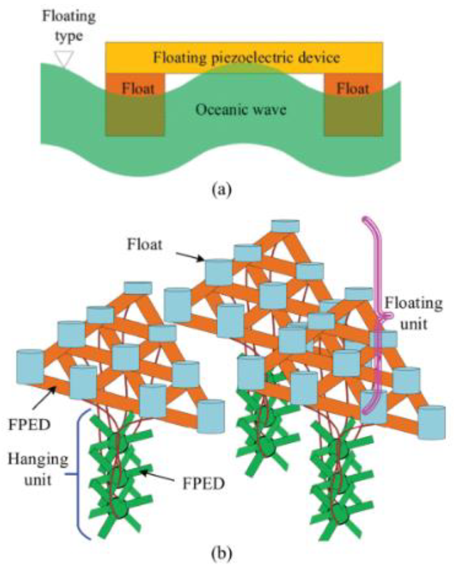
In [210], a piezoelectric material-based marine-energy harvester was built, as shown in Figure 15. A sheer marine cliff is just next to the harvester. It is made up of vertically stacked, thin piezoelectric sheets that are strained by passing ocean waves. As a result, wave movement is converted to electrical energy and sent to outward electronics.
Ref. [210] conducts an experimental test in water tanks on a floating elastic device with a hanging frame. Both unsettled and immersion-type buoys are employed in the investigation, as shown in Figure 16a. The test float’s height and breadth are 115 mm and 85 mm, respectively. In a wave tank, an artificial wave with an amplitude of 0.077 m and a wavelength of 1 m is formed. The FPED is positioned on the top of the float for submersible-based devices. It is put at the bottom of the floats in the context of a floating type of gadget. Attaching ropes/rods are cast off to connect the devices to the tank for both submerged and floating devices. Because FPEDs are formed of polyvinylidene fluoride, effective, electrical execution may be achieved by varying the length of the polyvinylidene fluoride layer from 0.1 mm to 0.5 mm, although not exceeding 0.5 mm is advised.
An isolated piezoelectric device can generate very little power. These gadgets must be gathered to improve power. As a result, Ref. [210] proposes a combined form of the floating elastic unit with a hanging structure (EFHAS) that may gather oceanic energy. As seen in Figure 16, it comprises a hanging and a floating component (b).
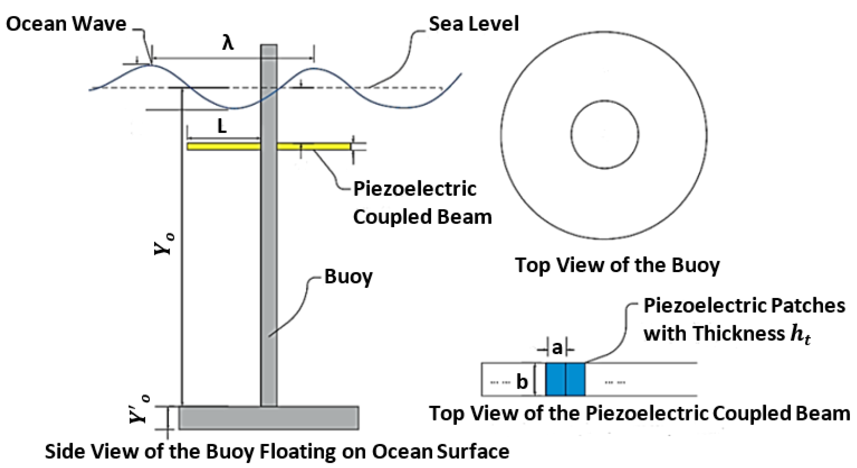
Using a piezoelectric coupled cantilever, Wu et al. devised a simple and less pricey method for using ocean waves as a source of energy. This piezoelectric harvester uses a cantilever coupled to a floating buoy to produce electricity from moderate and profound ocean waves. The specifications of the mentioned energy harvesting buoy are shown in Figure 17.
Finally, ocean-wave-motion energy collecting has been validated as a novel electrical energy source. A piezoelectric wave-energy harvester can create enough power for small-scale applications by capturing energy from the ocean’s waves. Table 6 below summarizes the research on extractors of piezoelectric waves for energy.
Using piezoelectric materials, by converting energy, certain systems have been created to gather flowing water energies in seas and rivers. In earlier decades, researchers developed eel-based energy harvesters to capture electrical power from motion in ocean or river water flows. This energy-collecting system mimics the motion of a swimming eel by exploiting the undulating motion of PVDF induced by vortices at the back of a bluff body. Taylor et al. developed and used eels to transfer mechanical energy from the water into electrical energy. They put the anticipated eel through its paces in a flow tank measuring 9.5 inches long, 3 inches wide, and 150 m thick. With the speed of the water at 0.5 ms−1, the collected voltage was estimated to be 3 V. In addition, if the VIV frequency and the flapping frequency were comparable, the harvester’s efficiency may be enhanced.

5. Future Challenges and Recommendations

The VIV, galloping, flutter, water flow, and ocean wave effects are employed in this paper to offer an overview of flow-induced energy harvesting systems. The working principles for the five phenomena are discussed. The best approach to acceptance is evaluating the potential of energy harvesting in actual scenarios and combining the requirements of relevant applications. Nevertheless, most efforts focused on the need for a comprehensive interdisciplinary examination and theoretical analysis. We realize that among the potential uses for low-power electronic components and self-powered gadgets, mechanical engineering, aeronautical engineering, pipeline engineering, biomedical engineering, and health care are just a few engineering fields that utilize wireless sensor networks. The key initiatives need to be prioritized to speed up piezoelectric energy harvesters’ development: investigating piezo harvesting from an energy policy perspective, lowering maintenance costs, extending durability, increasing productivity, and analyzing state assistance; the development of new applications for energy-recovery technology that needs less energy; pushing piezo material uses into new sectors such as the internet of things; and the investigation of mathematical models and analytical and numerical problem-solving approaches, notably in nanotechnology configurations when classical continuum mechanics constraints are broken or in chaotic and non-linear situations, and modified constitutive linkages may be required in non-continuum contexts. Furthermore, concerns such as studying such systems using the second law and from a thermodynamic standpoint are lacking. An additional barrier for nanoscale piezo-harvesters is the development of atomistic, ab initio first-principles simulations. Another interesting topic for future research is the incorporation of piezoelectric effect simulators into open-source technologies such as Open FOAM and LAMMPS. Review articles on optimization techniques or machine learning-related topics are highly encouraged because of the multi-physics nature of the piezoelectric effect. Several piezoelectric energy harvesters on the current market can generate power in the mW band. It may not be continuous, and power generation is frequently limited by low current output. It is preferable to develop substances with adequate adaptability and manufacturability, evidenced by higher (mandating a larger piezoelectric constant) and moderate voltage. Regrettably, capitalist industrial implementations are still constrained, and there is still space for further research into real-world engineering technologies.

6. Conclusions

The use of piezoelectric-energy harvesting has grown in popularity during the previous two decades. Several implantable energy-harvesting technologies are being developed by scientists to power portable gadgets and medical equipment. Thanks to new technologies, researchers have been able to fabricate highly flexible piezoelectric devices and electronics, paving the way for the development of biocompatible and long-lasting harvesters. Right now, much work is being done to improve energy-harvesting materials and methods. Piezoelectric energy harvesters’ circuits [216,217] need extra efforts in the future, such as, for example, proposing a self-powered footprint that does not need an external source for power. Each technique examined is best suited for a specific situation and has flaws in others. A suitable approach or design should be chosen based on the particular wind-flow conditions. Several factors influence the valuation of an energy harvester, including its size, transduction mechanism, and piezoelectric material type. Given the wireless sensor’s ever-reduced power requirement, an electrical sensing unit can be powered by a harvester at a centimeter scale. With the rapid advancement of technology, it is now possible to build a low-cost, fully self-powered WSN.
Developing a piezoelectric harvester based on vibration-power harvesting would make piezoelectric harvesters a viable alternative energy source in urban environments. Because wind speed is such an essential factor for wind-energy harvesters, further research into this parameter may increase harvester efficiency. The energy harvester’s frequency must be increased to produce more electricity from the water flow in home water pipes. The adopters with dual buoys are expected to maximize the performance of piezoelectric generators in wave-energy harvesters that employ piezoelectric materials. It was also suggested that future energy-gathering devices undertake fundamental biomimetic research.

Author Contributions

Conceptualization, A.A.; methodology, A.N. and A.A.; software, A.N. and A.A.; formal analysis, A.N.; investigation, A.N.; resources, A.A., W.A.A. and S.A.K.; writing—original draft preparation, A.N.; writing—review and editing, A.A., W.A.A. and S.A.K.; visualization, A.N.; supervision, A.A.; project administration, A.A., W.A.A. and S.A.K. All authors have read and agreed to the published version of the manuscript.

Funding

This research received no external funding.

Institutional Review Board Statement

Not applicable.

Informed Consent Statement

Not applicable.

Data Availability Statement

Not applicable.

Conflicts of Interest

The authors declare no conflict of interest.

References

  1. Yang, Z.; Zhou, S.; Zu, J.; Inman, D. High-Performance Piezoelectric Energy Harvesters and Their Applications. Joule 2018, 2, 642–697. [Google Scholar] [CrossRef] [Green Version]
  2. Laws, N.D.; Epps, B.P. Hydrokinetic energy conversion: Technology, research, and outlook. Renew. Sustain. Energy Rev. 2016, 57, 1245–1259. [Google Scholar] [CrossRef] [Green Version]
  3. Zhao, L.-C.; Zou, H.X.; Yan, G.; Liu, F.R.; Tan, T.; Zhang, W.M.; Peng, Z.K.; Meng, G. A water-proof magnetically coupled piezoelectric-electromagnetic hybrid wind energy harvester. Appl. Energy 2019, 239, 735–746. [Google Scholar] [CrossRef]
  4. Rome, L.C.; Flynn, L.; Goldman, E.M.; Yoo, T.D. Generating Electricity While Walking with Loads. Science 2005, 309, 1725–1728. [Google Scholar] [CrossRef] [PubMed] [Green Version]
  5. Daqaq, M.F.; Masana, R.; Erturk, A.; Dane Quinn, D. On the Role of Nonlinearities in Vibratory Energy Harvesting: A Critical Review and Discussion. Appl. Mech. Rev. 2014, 66, 040801. [Google Scholar] [CrossRef]
  6. Yildirim, T.; Ghayesh, M.H.; Li, W.; Alici, G. A review on performance enhancement techniques for ambient vibration energy harvesters. Renew. Sustain. Energy Rev. 2017, 71, 435–449. [Google Scholar] [CrossRef] [Green Version]
  7. Shaikh, F.K.; Zeadally, S. Energy harvesting in wireless sensor networks: A comprehensive review. Renew. Sustain. Energy Rev. 2016, 55, 1041–1054. [Google Scholar] [CrossRef]
  8. Seah, W.K.G.; Eu, Z.A.; Tan, H.-P. Wireless sensor networks powered by ambient energy harvesting (WSN-HEAP)—Survey and challenges. In Proceedings of the 2009 1st International Conference on Wireless Communication, Vehicular Technology, Information Theory and Aerospace Electronic Systems Technology, Aalborg, Denmark, 17–20 May 2009; pp. 1–5. [Google Scholar] [CrossRef]
  9. Verma, G.; Sharma, V.; Pughat, A. Energy harvesting issues in wireless sensor networks. In Energy-Efficient Wireless Sensor Networks; CRC Press: Boca Raton, FL, USA, 2017; pp. 137–163. [Google Scholar] [CrossRef]
  10. Kouritem, S.A. Array of piezoelectric energy harvesters for broadband natural frequency applications. In Proceedings of the ICSV27, Annual Congress of International Institute of Acoustics and Vibration (IIAV), Prague, Czech Republic, 11–16 July 2021. [Google Scholar]
  11. Paulo, J.; Gaspar, P.D. Review and future trend of energy harvesting methods for portable medical devices. In Proceedings of the World Congress on Engineering, London, UK, 30 June–2 July 2010; Volume 2, pp. 909–914. [Google Scholar]
  12. Bowen, C.R.; Taylor, J.; LeBoulbar, E.; Zabek, D.; Chauhan, A.; Vaish, R. Pyroelectric materials and devices for energy harvesting applications. Energy Environ. Sci. 2014, 7, 3836–3856. [Google Scholar] [CrossRef]
  13. Abdelkefi, A. Aeroelastic energy harvesting: A review. Int. J. Eng. Sci. 2016, 100, 112–135. [Google Scholar] [CrossRef]
  14. Trolier-McKinstry, S.; Zhang, S.; Bell, A.J.; Tan, X. High-Performance Piezoelectric Crystals, Ceramics, and Films. Annu. Rev. Mater. Res. 2018, 48, 191–217. [Google Scholar] [CrossRef] [Green Version]
  15. Zhang, S.; Li, F.; Jiang, X.; Kim, J.; Luo, J.; Geng, X. Advantages and challenges of relaxor-PbTiO3 ferroelectric crystals for electroacoustic transducers—A review. Prog. Mater. Sci. 2015, 68, 1–66. [Google Scholar] [CrossRef] [Green Version]
  16. Brosnan, K.H.; Messing, G.L.; Markley, D.C.; Meyer, R.J. Comparison of the properties of tonpilz transducers fabricated with ⟨001⟩ fiber-textured lead magnesium niobate-lead titanate ceramic and single crystals. J. Acoust. Soc. Am. 2009, 126, 2257–2265. [Google Scholar] [CrossRef]
  17. Levassort, F.; Thi, M.P.; Marechal, P.; Tran-Huu-Hue, L.-P.; Lethiecq, M. Ultrasonic transducer based on highly textured PMN-PT piezoelectric ceramic. J. Electroceram. 2007, 19, 375–381. [Google Scholar] [CrossRef]
  18. Levassort, F.; Pham Thi, M.; Hemery, H.; Marechal, P.; Tran-Huu-Hue, L.-P.; Lethiecq, M. Piezoelectric textured ceramics: Effective properties and application to ultrasonic transducers. Ultrasonics 2006, 44, e621–e626. [Google Scholar] [CrossRef]
  19. Muralt, P. Ferroelectric thin films for micro-sensors and actuators: A review. J. Micromech. Microeng. 2000, 10, 136–146. [Google Scholar] [CrossRef]
  20. Zhang, H.; Zhou, J.; Shen, J.; Yang, X.; Wu, C.; Han, K.; Zhao, Z.; Chen, W. Enhanced piezoelectric property and promoted depolarization temperature in Fe doped Bi1/2(Na0.8K0.2)1/2TiO3 lead-free ceramics. Ceram. Int. 2017, 43, 16395–16402. [Google Scholar] [CrossRef]
  21. Dagdeviren, C.; Joe, P.; Tuzman, O.L.; Park, K.I.; Lee, K.J.; Shi, Y.; Huang, Y.; Rogers, J.A. Recent progress in flexible and stretchable piezoelectric devices for mechanical energy harvesting, sensing and actuation. Extrem. Mech. Lett. 2016, 9, 269–281. [Google Scholar] [CrossRef] [Green Version]
  22. Chen, Y.; Zhang, Y.; Zhang, L.; Ding, F.; Schmidt, O.G. Scalable single crystalline PMN-PT nanobelts sculpted from bulk for energy harvesting. Nano Energy 2017, 31, 239–246. [Google Scholar] [CrossRef]
  23. Bani-Hani, M.; Almomani, A.; Aljanaideh, K.; Kouritem, S.A. Mechanical Modeling and Numerical Investigation of Earthquake-Induced Structural Vibration Self Powered Sensing Device. IEEE Sens. J. 2022, preprint. [Google Scholar] [CrossRef]
  24. Yan, X.; Cui, X.; Li, B.; Li, L. Large, Solution-Processable Graphene Quantum Dots as Light Absorbers for Photovoltaics. Nano Lett. 2010, 10, 1869–1873. [Google Scholar] [CrossRef] [PubMed]
  25. Kouritem, S.A.; Al-Moghazy, M.A.; Noori, M.; Altabey, W.A. Mass tuning technique for a broadband piezoelectric energy harvester array. Mech. Syst. Signal Process. 2022, 181, 109500. [Google Scholar] [CrossRef]
  26. Mohamed, K.T.; El-Gamal, H.A.; Kouritem, S.A. An Experimental Validation of a New Shape Optimization Technique for Piezoelectric Harvesting Cantilever Beams. Alex. Eng. J. 2021, 60, 1751–1766. [Google Scholar] [CrossRef]
  27. Husain, A.A.F.; Hasan, W.Z.W.; Shafie, S.; Hamidon, M.N.; Pandey, S.S. A review of transparent solar photovoltaic technologies. Renew. Sustain. Energy Rev. 2018, 94, 779–791. [Google Scholar] [CrossRef]
  28. Seyedmahmoudian, M.; Kok Soon, T.; Jamei, E.; Thirunavukkarasu, G.S.; Horan, B.; Mekhilef, S.; Stojcevski, A. Maximum Power Point Tracking for Photovoltaic Systems under Partial Shading Conditions Using Bat Algorithm. Sustainability 2018, 10, 1347. [Google Scholar] [CrossRef] [Green Version]
  29. Tiwari, G.N.; Mishra, R.K.; Solanki, S.C. Photovoltaic modules and their applications: A review on thermal modelling. Appl. Energy 2011, 88, 2287–2304. [Google Scholar] [CrossRef]
  30. Frischmann, P.D.; Mahata, K.; Würthner, F. Powering the future of molecular artificial photosynthesis with light-harvesting metallosupramolecular dye assemblies. Chem. Soc. Rev. 2013, 42, 1847–1870. [Google Scholar] [CrossRef]
  31. Tian, R.; Wan, C.; Hayashi, N.; Aoai, T.; Koumoto, K. Wearable and flexible thermoelectrics for energy harvesting. MRS Bull. 2018, 43, 193–198. [Google Scholar] [CrossRef]
  32. Salem, M.S.; Ahmed, S.; Shaker, A.; Alshammari, M.T.; Al-Dhlan, K.A.; Alanazi, A.; Saeed, A.; Abouelatta, M. Bandwidth Broadening of Piezoelectric Energy Harvesters Using Arrays of a Proposed Piezoelectric Cantilever Structure. Micromachines 2021, 12, 973. [Google Scholar] [CrossRef]
  33. Blackburn, J.L.; Ferguson, A.J.; Cho, C.; Grunlan, J.C. Carbon-Nanotube-Based Thermoelectric Materials and Devices. Adv. Mater. 2018, 30, 1704386. [Google Scholar] [CrossRef]
  34. Hunter, S.R.; Lavrik, N.V.; Mostafa, S.; Rajic, S.; Datskos, P.G. Review of pyroelectric thermal energy harvesting and new MEMs-based resonant energy conversion techniques. In Energy Harvesting and Storage: Materials, Devices, and Applications III; SPIE: Baltimore, MD, USA, 2012; Volume 8377, pp. 77–90. [Google Scholar] [CrossRef]
  35. Cuadras, A.; Gasulla, M.; Ferrari, V. Thermal energy harvesting through pyroelectricity. Sens. Actuators A Phys. 2010, 158, 132–139. [Google Scholar] [CrossRef]
  36. Mondal, S.; Chowdhury, A.R.; Kanu, A.; Bhattacharjee, S. Piezoelectric Energy Harvesting by Utilizing Angular Speed Variation in High-Speed Rotating Beams by Utilizing Angular Speed Variation in High-Speed Rotating Beams. Bachelor’s Thesis, National Institute of Technology, Durgapur, India, May 2022. [Google Scholar] [CrossRef]
  37. Narita, F.; Fox, M. A Review on Piezoelectric, Magnetostrictive, and Magnetoelectric Materials and Device Technologies for Energy Harvesting Applications. Adv. Eng. Mater. 2018, 20, 1700743. [Google Scholar] [CrossRef] [Green Version]
  38. Wang, H.; Jasim, A.; Chen, X. Energy harvesting technologies in roadway and bridge for different applications—A comprehensive review. Appl. Energy 2018, 212, 1083–1094. [Google Scholar] [CrossRef]
  39. Stephen, N.G. On energy harvesting from ambient vibration. J. Sound Vib. 2006, 293, 409–425. [Google Scholar] [CrossRef] [Green Version]
  40. Saadon, S.; Sidek, O. A review of vibration-based MEMS piezoelectric energy harvesters. Energy Convers. Manag. 2011, 52, 500–504. [Google Scholar] [CrossRef]
  41. Harne, R.L.; Wang, K.W. A review of the recent research on vibration energy harvesting via bistable systems. Smart Mater. Struct. 2013, 22, 23001. [Google Scholar] [CrossRef]
  42. Sriphan, S.; Vittayakorn, N. Hybrid piezoelectric-triboelectric nanogenerators for flexible electronics: Recent advances and perspectives. J. Sci. Adv. Mater. Devices 2022, 7, 100461. [Google Scholar] [CrossRef]
  43. Shi, Q.; Sun, Z.; Zhang, Z.; Le, C. Triboelectric Nanogenerators and Hybridized Systems for Enabling Next-Generation IoT Applications. Research 2021, 2021, 6849171. [Google Scholar] [CrossRef]
  44. Huang, C.; Chen, G.; Nashalian, A.; Chen, J. Advances in self-powered chemical sensing via a triboelectric nanogenerator. Nanoscale 2021, 13, 2065–2081. [Google Scholar] [CrossRef]
  45. Dani, S.; Tripathy, A.; Alluri, N.; Balasubramaniam, S.; Ramadoss, A. A Critical Review: Impact of Electrical Poling on Longitudinal Piezoelectric Strain Coefficient. Mater. Adv. 2022, in press. [CrossRef]
  46. Liu, H.; Zhong, J.; Lee, C.; Lee, S.; Lin, L. A comprehensive review on piezoelectric energy harvesting technology: Materials, mechanisms, and applications. Appl. Phys. Rev. 2018, 5, 041306. [Google Scholar] [CrossRef] [Green Version]
  47. Lee, B.; Lin, S.; Wu, W.; Wang, X.; Chang, P.; Lee, C. Piezoelectric MEMS generators fabricated with an aerosol deposition PZT thin film. J. Micromech. Microeng. 2009, 19, 065014. [Google Scholar] [CrossRef]
  48. Kim, S.; Park, H.; Kim, S.; Wikle, H.; Park, J.; Kim, D. Comparison of MEMS PZT Cantilevers Based on d31 and d33 Modes for Vibration Energy Harvesting. J. Microelectromech. Syst. 2013, 22, 26–33. [Google Scholar] [CrossRef]
  49. Wu, Y.; Ma, Y.; Zheng, H.; Ramakrishna, S. Piezoelectric materials for flexible and wearable electronics: A review. Mater. Des. 2021, 211, 110164. [Google Scholar] [CrossRef]
  50. Wang, C.; Yu, Y.; Yuan, Y.; Ren, C.; Liao, Q.; Wang, J.; Chai, Z.; Li, Q.; Li, Z. Heartbeat-Sensing Mechanoluminescent Device Based on a Quantitative Relationship between Pressure and Emissive Intensity. Matter 2020, 2, 181–193. [Google Scholar] [CrossRef] [Green Version]
  51. Aliqué, M.; Simão, C.; Murillo, G.; Moya, A. Fully-Printed Piezoelectric Devices for Flexible Electronics Applications. Adv. Mater. Technol. 2021, 6, 2001020. [Google Scholar] [CrossRef]
  52. Kim, H.; Lee, D.W.; Kim, D.H.; Kong, D.S.; Choi, J.; Lee, M.; Murillo, G.; Jung, J.H. Dominant Role of Young’s Modulus for Electric Power Generation in PVDF–BaTiO3 Composite-Based Piezoelectric Nanogenerator. Nanomaterials 2018, 8, 777. [Google Scholar] [CrossRef]
  53. Lee, H.; Zhang, S.; Bar-Cohen, Y.; Sherrit, S. High Temperature, High Power Piezoelectric Composite Transducers. Sensors 2014, 14, 14526–14552. [Google Scholar] [CrossRef] [Green Version]
  54. Smith, W.; Auld, B. Modeling 1-3 composite piezoelectrics: Thickness-mode oscillations. IEEE Trans. Ultrason. Ferroelectr. Freq. Control 1991, 38, 40–47. [Google Scholar] [CrossRef]
  55. Li, W.; Chen, X. Compensation of hysteresis in piezoelectric actuators without dynamics modeling. Sens. Actuators A Phys. 2013, 199, 89–97. [Google Scholar] [CrossRef]
  56. Li, W.; Chen, X.; Li, Z. Inverse compensation for hysteresis in piezoelectric actuator using an asymmetric rate-dependent model. Rev. Sci. Instrum. 2013, 84, 115003. [Google Scholar] [CrossRef]
  57. Sezer, N.; Koç, M. A comprehensive review on the state-of-the-art of piezoelectric energy harvesting. Nano Energy 2021, 80, 105567. [Google Scholar] [CrossRef]
  58. Siang, J.; Lim, M.; Salman Leong, M. Review of vibration-based energy harvesting technology: Mechanism and architectural approach. Int. J. Energy Res. 2018, 42, 1866–1893. [Google Scholar] [CrossRef]
  59. Ansari, M.; Somdee, P. Piezoelectric Polymeric Foams as Flexible Energy Harvesters: A Review. Adv. Energy Sustain. Res. 2022, 3, 2200063. [Google Scholar] [CrossRef]
  60. Shan, X.; Song, R.; Liu, B.; Xie, T. Novel energy harvesting: A macro fiber composite piezoelectric energy harvester in the water vortex. Ceram. Int. 2015, 41 (Suppl. S1), S763–S767. [Google Scholar] [CrossRef]
  61. Safaei, M.; Sodano, H.A.; Anton, S.R. A review of energy harvesting using piezoelectric materials: State-of-the-art a decade later (2008–2018). Smart Mater. Struct. 2019, 28, 113001. [Google Scholar] [CrossRef]
  62. Abrol, S.; Chhabra, D. Harvesting piezoelectricity using different structures by utilizing fluid flow interactions. Int. J. R D Eng. Sci. Manag. 2017, 5, 24–36. [Google Scholar]
  63. Chen, Z.; Guo, B.; Yang, Y.; Cheng, C. Metamaterials-based enhanced energy harvesting: A review. Phys. B Condens. Matter 2014, 438, 1–8. [Google Scholar] [CrossRef]
  64. Anton, S.R.; Sodano, H.A. A review of power harvesting using piezoelectric materials (2003–2006). Smart Mater. Struct. 2007, 16, R1–R21. [Google Scholar] [CrossRef]
  65. Tien, C.M.T.; Goo, N.S. Use of a piezo-composite generating element for harvesting wind energy in an urban region. Aircr. Eng. Aerosp. Technol. 2010, 82, 376–381. [Google Scholar] [CrossRef]
  66. Zeng, P.; Khaligh, A. A Permanent-Magnet Linear Motion Driven Kinetic Energy Harvester. IEEE Trans. Ind. Electron. 2013, 60, 5737–5746. [Google Scholar] [CrossRef]
  67. Tang, Q.; Li, X. Two-Stage Wideband Energy Harvester Driven by Multimode Coupled Vibration. IEEE ASME Trans. Mechatron. 2015, 20, 115–121. [Google Scholar] [CrossRef]
  68. Sankman, J.; Ma, D. A 12-μW to 1.1-mW AIM Piezoelectric Energy Harvester for Time-Varying Vibrations with 450-nA. IEEE Trans. Power Electron. 2015, 30, 632–643. [Google Scholar] [CrossRef]
  69. Dallago, E.; Barnabei, A.L.; Liberale, A.; Malcovati, P.; Venchi, G. An Interface Circuit for Low-Voltage Low-Current Energy Harvesting Systems. IEEE Trans. Power Electron. 2015, 30, 1411–1420. [Google Scholar] [CrossRef]
  70. Ziegler, S.; Woodward, R.C.; Iu, H.H.-C.; Borle, L.J. Current Sensing Techniques: A Review. IEEE Sens. J. 2009, 9, 354–376. [Google Scholar] [CrossRef]
  71. Tan, Y.K.; Panda, S.K. Self-Autonomous Wireless Sensor Nodes with Wind Energy Harvesting for Remote Sensing of Wind-Driven Wildfire Spread. IEEE Trans. Instrum. Meas. 2011, 60, 1367–1377. [Google Scholar] [CrossRef]
  72. Zhao, L.; Yang, Y. Toward Small-Scale Wind Energy Harvesting: Design, Enhancement, Performance Comparison, and Applicability. Shock Vib. 2017, 2017, 3585972. [Google Scholar] [CrossRef]
  73. Ovejas, V.J.; Cuadras, A. Multimodal piezoelectric wind energy harvesters. Smart Mater. Struct. 2011, 20, 85030. [Google Scholar] [CrossRef]
  74. Yadav, N.; Baredar, P. A review on piezoelectric energy harvesting system using vortex induced vibration. AIP Conf. Proc. 2018, 2039, 020054. [Google Scholar] [CrossRef]
  75. Yang, Y.; Shen, Q.; Jin, J.; Wang, Y.; Qian, W.; Yuan, D. Rotational piezoelectric wind energy harvesting using impact-induced resonance. Appl. Phys. Lett. 2014, 105, 53901. [Google Scholar] [CrossRef]
  76. Rancourt, D.; Tabesh, A. Evaluation of centimeter-scale micro windmills: Aerodynamics and electromagnetic power generation. Dig. Power MEMS 2017, 2007, 93–96. [Google Scholar]
  77. Bansal, A.; Howey, D.A.; Holmes, A.S. CM-scale air turbine and generator for energy harvesting from low-speed flows. In Proceedings of the TRANSDUCERS 2009—2009 International Solid-State Sensors, Actuators and Microsystems Conference, Denver, CO, USA, 21–25 June 2009; pp. 529–532. [Google Scholar] [CrossRef] [Green Version]
  78. Howey, D.A.; Bansal, A.; Holmes, A.S. Design and performance of a centimetre-scale shrouded wind turbine for energy harvesting. Smart Mater. Struct. 2011, 20, 85021. [Google Scholar] [CrossRef] [Green Version]
  79. Priya, S.; Chen, C.-T.; Fye, D.; Zahnd, J. Piezoelectric Windmill: A Novel Solution to Remote Sensing. Jpn. J. Appl. Phys. 2004, 44, L104–L107. [Google Scholar] [CrossRef] [Green Version]
  80. Karami, M.A.; Farmer, J.R.; Inman, D.J. Parametrically excited nonlinear piezoelectric compact wind turbine. Renew. Energy 2013, 50, 977–987. [Google Scholar] [CrossRef]
  81. Bressers, S.; Avirovik, D.; Lallart, M.; Inman, D.J.; Priya, S. Contact-less Wind Turbine Utilizing Piezoelectric Bimorphs with Magnetic Actuation. Struct. Dyn. 2011, 3, 233–243. [Google Scholar]
  82. Chen, C.-T.; Islam, R.A.; Priya, S. Electric energy generator. IEEE Trans. Ultrason. Ferroelectr. Freq. Control 2006, 53, 656–661. [Google Scholar] [CrossRef] [PubMed]
  83. Liya, Z. Small-Scale Wind Energy Harvesting Using Piezoelectric Materials. Nanyan Techonol. Univ. 2021, 2015. [Google Scholar] [CrossRef]
  84. Allen, J.J.; Smits, A.J. Energy Harvesting EEL. J. Fluids Struct. 2001, 15, 629–640. [Google Scholar] [CrossRef] [Green Version]
  85. Gao, X.; Shih, W.-H.; Shih, W.Y. Flow Energy Harvesting Using Piezoelectric Cantilevers with Cylindrical Extension. IEEE Trans. Ind. Electron. 2013, 60, 1116–1118. [Google Scholar] [CrossRef]
  86. McKinney, W.; DeLaurier, J. Wingmill: An Oscillating-Wing Windmill. J. Energy 1981, 5, 109–115. [Google Scholar] [CrossRef]
  87. Bryant, M.; Garcia, E. Modeling and Testing of a Novel Aeroelastic Flutter Energy Harvester. J. Vib. Acoust. 2011, 133, 011010. [Google Scholar] [CrossRef]
  88. Bryant, M.; Garcia, E. Energy harvesting: A key to wireless sensor nodes. In Proceedings of the Second International Conference on Smart Materials and Nanotechnology in Engineering, Weihai, China, 8–11 July 2009; Volume 7493, pp. 523–530. [Google Scholar] [CrossRef]
  89. Bryant, M.; Tse, R.; Garcia, E. Investigation of Host Structure Compliance in Aeroelastic Energy Harvesting. Smart Mater. Adapt. Struct. Intell. Syst. 2012, 2, 769–775. [Google Scholar] [CrossRef]
  90. Bryant, M.; Pizzonia, M.; Mehallow, M.; Garcia, E. Energy harvesting for self-powered aerostructure actuation. In Proceedings of the Active and Passive Smart Structures and Integrated Systems, San Diego, CA, USA, 10–13 March 2014; Volume 9057, pp. 121–129. [Google Scholar] [CrossRef]
  91. Bryant, M.; Schlichting, A.D.; Garcia, E. Toward efficient aeroelastic energy harvesting: Device performance comparisons and improvements through synchronized switching. In Proceedings of the Active and Passive Smart Structures and Integrated Systems, San Diego, CA, USA, 10–14 March 2013; Volume 8688, pp. 33–42. [Google Scholar] [CrossRef]
  92. Bryant, M.; Wolff, E.; Garcia, E. Parametric design study of an aeroelastic flutter energy harvester. In Proceedings of the SPIE Smart Structures and Materials + Nondestructive Evaluation and Health Monitoring, San Diego, CA, USA, 8–12 March 2011; Volume 7977. [Google Scholar] [CrossRef]
  93. Erturk, A.; Vieira, W.G.R.; De Marqui, C.; Inman, D.J. On the energy harvesting potential of piezoaeroelastic systems. Appl. Phys. Lett. 2010, 96, 184103. [Google Scholar] [CrossRef]
  94. Erturk, A.; Bilgen, O.; Fontenille, M.; Inman, D.J. Piezoelectric energy harvesting from macro-fiber composites with an application to morphing-wing aircrafts. In Proceedings of the 19th International Conference on Adaptive Structures and Technologies, Ascona, Switzerland, 6–9 October 2008; pp. 339–359. [Google Scholar]
  95. Boragno, C.; Festa, R.; Mazzino, A. Elastically bounded flapping wing for energy harvesting. Appl. Phys. Lett. 2012, 100, 253906. [Google Scholar] [CrossRef]
  96. Sousa, V.C.; Anicézio, M.D.M.; De Marqui, C., Jr.; Erturk, A. Enhanced aeroelastic energy harvesting by exploiting combined nonlinearities: Theory and experiment. Smart Mater. Struct. 2011, 20, 94007. [Google Scholar] [CrossRef]
  97. Li, S.; Lipson, H. Vertical-Stalk Flapping-Leaf Generator for Wind Energy Harvesting. Smart Mater. Adapt. Struct. Intell. Syst. 2009, 21, 611–619. [Google Scholar] [CrossRef] [Green Version]
  98. Wu, L.; Jin, Z.; Liu, Y.; Ning, H.; Liu, X.; Hu, N. Recent advances in the preparation of PVDF-based piezoelectric materials. Nanotechnol. Rev. 2022, 11, 1386–1407. [Google Scholar] [CrossRef]
  99. Deivasigamani, A.; McCarthy, J.M.; John, S.; Watkins, S.; Trivailo, P.; Coman, F. Piezoelectric energy harvesting from wind using coupled bending-torsional vibrations. Mod. Appl. Sci. 2014, 8, 106–126. [Google Scholar] [CrossRef]
  100. De Marqui Junior, C.; Erturk, A.; Inman, D.J. An electromechanical finite element model for piezoelectric energy harvester plates. J. Sound Vib. 2009, 327, 9–25. [Google Scholar] [CrossRef]
  101. Hobeck, J.D.; Geslain, D.; Inman, D.J. The dual cantilever flutter phenomenon: A novel energy harvesting method. In Proceedings of the SPIE Smart Structures and Materials + Nondestructive Evaluation and Health Monitoring, San Diego, CA, USA, 9–13 March 2014; Volume 9061. [Google Scholar] [CrossRef]
  102. Naudascher, E.; Rockwell, D. Oscillator-Model Approach to Theidentification and Assessment Offlow-Induced Vibrations in a System. J. Hydraul. Res. 1980, 18, 59–82. [Google Scholar] [CrossRef]
  103. Argentina, M.; Mahadevan, L. Fluid-flow-induced flutter of a flag. Proc. Natl. Acad. Sci. USA 2005, 102, 1829–1834. [Google Scholar] [CrossRef] [PubMed] [Green Version]
  104. McCarthy, J.M.; Watkins, S.; Deivasigamani, A.; John, S.J. Fluttering energy harvesters in the wind: A review. J. Sound Vib. 2016, 361, 355–377. [Google Scholar] [CrossRef]
  105. Yamaguchi, N.; Yokota, K.; Tsujimoto, Y. Flutter Limits and Behaviors of a Flexible Thin Sheet in High-Speed Flow—I: Analytical Method for Prediction of the Sheet Behavior. J. Fluids Eng. 1999, 122, 65–73. [Google Scholar] [CrossRef]
  106. Kashyap, A.S.; Vidya Shankar, K.V.; Vignesh, S. Renewable energy from vortex induced vibrations in a slow moving fluid. In Proceedings of the 2010 International Conference on Environmental Engineering and Applications, Singapore, 10–12 September 2010; pp. 263–266. [Google Scholar] [CrossRef]
  107. Akaydin, H.D.; Elvin, N.; Andreopoulos, Y. The performance of a self-excited fluidic energy harvester. Smart Mater. Struct. 2012, 21, 25007. [Google Scholar] [CrossRef]
  108. Weinstein, L.A.; Cacan, M.R.; So, P.M.; Wright, P.K. Vortex shedding induced energy harvesting from piezoelectric materials in heating, ventilation and air conditioning flows. Smart Mater. Struct. 2012, 21, 45003. [Google Scholar] [CrossRef]
  109. Goushcha, O.; Elvin, N.; Andreopoulos, Y. Interactions of vortices with a flexible beam with applications in fluidic energy harvesting. Appl. Phys. Lett. 2014, 104, 21919. [Google Scholar] [CrossRef]
  110. Xu-Xu, J.; Barrero-Gil, A.; Velazquez, A. Dual mass system for enhancing energy extraction from Vortex-Induced Vibrations of a circular cylinder. Int. J. Mar. Energy 2016, 16, 250–261. [Google Scholar] [CrossRef]
  111. Wang, D.-A.; Ko, H.-H. Piezoelectric energy harvesting from flow-induced vibration. J. Micromech. Microeng. 2010, 20, 25019. [Google Scholar] [CrossRef]
  112. Wang, D.-A.; Chang, K.-H. Electromagnetic energy harvesting from flow induced vibration. Microelectron. J. 2010, 41, 356–364. [Google Scholar] [CrossRef]
  113. Williamson, J.D.B.S.J.; Stark, B.H. Low Head Pico Hydro Turbine Selection using a Multi-Criteria Analysis. In Proceedings of the World Renewable Energy Congress, Linköping, Sweden, 8–13 May 2011; Volume 6, pp. 1337–1385. Available online: https://ep.liu.se/ecp/057/vol6/ecp057vol6.pdf#page=5 (accessed on 11 August 2022).
  114. Tam Nguyen, H.-D.; Pham, H.-T.; Wang, D.-A. A miniature pneumatic energy generator using Kármán vortex street. J. Wind Eng. Ind. Aerodyn. 2013, 116, 40–48. [Google Scholar] [CrossRef]
  115. Wang, J.; Ran, J.; Zhang, Z. Energy Harvester Based on the Synchronization Phenomenon of a Circular Cylinder. Math. Probl. Eng. 2014, 2014, 567357. [Google Scholar] [CrossRef] [Green Version]
  116. Petrini, F.; Gkoumas, K. Piezoelectric energy harvesting from vortex shedding and galloping induced vibrations inside HVAC ducts. Energy Build. 2018, 158, 371–383. [Google Scholar] [CrossRef]
  117. Barrero-Gil, A.; Alonso, G.; Sanz-Andres, A. Energy harvesting from transverse galloping. J. Sound Vib. 2010, 329, 2873–2883. [Google Scholar] [CrossRef]
  118. Sorribes-Palmer, F.; Sanz-Andres, A. Optimization of energy extraction in transverse galloping. J. Fluids Struct. 2013, 43, 124–144. [Google Scholar] [CrossRef] [Green Version]
  119. Sirohi, J.; Mahadik, R. Piezoelectric wind energy harvester for low-power sensors. J. Intell. Mater. Syst. Struct. 2011, 22, 2215–2228. [Google Scholar] [CrossRef]
  120. Sirohi, J.; Mahadik, R. Harvesting Wind Energy Using a Galloping Piezoelectric Beam. J. Vib. Acoust. 2011, 134, 011009. [Google Scholar] [CrossRef]
  121. Abdelkefi, A.; Hajj, M.R.; Nayfeh, A.H. Power harvesting from transverse galloping of square cylinder. Nonlinear Dyn. 2012, 70, 1355–1363. [Google Scholar] [CrossRef]
  122. Abdelkefi, A.; Yan, Z.; Hajj, M.R. Performance analysis of galloping-based piezoaeroelastic energy harvesters with different cross-section geometries. J. Intell. Mater. Syst. Struct. 2013, 25, 246–256. [Google Scholar] [CrossRef]
  123. Yang, Y.; Zhao, L.; Tang, L. Comparative study of tip cross-sections for efficient galloping energy harvesting. Appl. Phys. Lett. 2013, 102, 64105. [Google Scholar] [CrossRef]
  124. Daqaq, M.F. Characterizing the response of galloping energy harvesters using actual wind statistics. J. Sound Vib. 2015, 357, 365–376. [Google Scholar] [CrossRef] [Green Version]
  125. Bibo, A.; Daqaq, M.F. An analytical framework for the design and comparative analysis of galloping energy harvesters under quasi-steady aerodynamics. Smart Mater. Struct. 2015, 24, 94006. [Google Scholar] [CrossRef]
  126. Bibo, A.; Daqaq, M.F. On the optimal performance and universal design curves of galloping energy harvesters. Appl. Phys. Lett. 2014, 104, 23901. [Google Scholar] [CrossRef]
  127. Vicente-Ludlam, D.; Barrero-Gil, A.; Velazquez, A. Enhanced mechanical energy extraction from transverse galloping using a dual mass system. J. Sound Vib. 2015, 339, 290–303. [Google Scholar] [CrossRef]
  128. Pellegrini, S.P.; Tolou, N.; Schenk, M.; Herder, J.L. Bistable vibration energy harvesters: A review. J. Intell. Mater. Syst. Struct. 2013, 24, 1303–1312. [Google Scholar] [CrossRef]
  129. Tang, L.; Yang, Y.; Soh, C.K. Toward broadband vibration-based energy harvesting. J. Intell. Mater. Syst. Struct. 2010, 21, 1867–1897. [Google Scholar] [CrossRef]
  130. Zhao, L.; Tang, L.; Yang, Y. Small Wind Energy Harvesting from Galloping Using Piezoelectric Materials. Smart Mater. Adapt. Struct. Intell. Syst. 2012, 2, 919–927. [Google Scholar] [CrossRef]
  131. Erturk, A. Electromechanical Modeling of Piezoelectric Energy Harvesters. Ph.D. Dissertation, Virginia Polytechnic Institute and State University, Blacksburg, VA, USA, 2009. [Google Scholar]
  132. Stanton, S.C.; Erturk, A.; Mann, B.P.; Inman, D.J. Nonlinear piezoelectricity in electroelastic energy harvesters: Modeling and experimental identification. J. Appl. Phys. 2010, 108, 074903. [Google Scholar] [CrossRef] [Green Version]
  133. Renno, J.M.; Daqaq, M.F.; Inman, D.J. On the optimal energy harvesting from a vibration source. J. Sound Vib. 2009, 320, 386–405. [Google Scholar] [CrossRef]
  134. Hamlehdar, M.; Kasaeian, A.; Safaei, M.R. Energy Harvesting from Fluid Flow Using Piezoelectrics: A Critical Review. Renew. Energy 2019, 143, 1826–1838. [Google Scholar] [CrossRef]
  135. Abdelkefi, A.; Najar, F.; Nayfeh, A.H.; Ben Ayed, S. An energy harvester using piezoelectric cantilever beams undergoing coupled bending-torsion vibrations. Smart Mater. Struct. 2011, 20, 115007. [Google Scholar] [CrossRef]
  136. Myers, R.; Vickers, M.; Kim, H.; Priya, S. Small scale windmill. Appl. Phys. Lett. 2007, 90, 54106. [Google Scholar] [CrossRef]
  137. Rezaei-Hosseinabadi, N.; Tabesh, A.; Dehghani, R.; Aghili, A. An Efficient Piezoelectric Windmill Topology for Energy Harvesting from Low-Speed Air Flows. IEEE Trans. Ind. Electron. 2015, 62, 3576–3583. [Google Scholar] [CrossRef]
  138. Stamatellou, A.-M.; Kalfas, A.I. Experimental investigation of energy harvesting from swirling flows using a piezoelectric film transducer. Energy Convers. Manag. 2018, 171, 1405–1415. [Google Scholar] [CrossRef]
  139. Hobeck, J.D.; Inman, D.J. Artificial piezoelectric grass for energy harvesting from turbulence-induced vibration. Smart Mater. Struct. 2012, 21, 105024. [Google Scholar] [CrossRef] [Green Version]
  140. Orrego, S.; Shoele, K.; Ruas, A.; Doran, K.; Caggiano, B.; Mittal, R.; Kang, S.H. Harvesting ambient wind energy with an inverted piezoelectric flag. Appl. Energy 2017, 194, 212–222. [Google Scholar] [CrossRef]
  141. Jun Li, D.; Hong, S.; Gu, S.; Choi, Y.; Nakhmanson, S.; Heinonen, O.; Karpeev, D.; No, K. Polymer piezoelectric energy harvesters for low wind speed. Appl. Phys. Lett. 2014, 104, 12902. [Google Scholar] [CrossRef]
  142. Priya, S. Modeling of electric energy harvesting using piezoelectric windmill. Appl. Phys. Lett. 2005, 87, 184101. [Google Scholar] [CrossRef]
  143. Wang, K.X.; Bu, L.; Chen, J.M.; Song, L. Frequency-tunable airflow energy harvester using variable aperture helmholtz resonator and piezoelectric cantilever. In Proceedings of the 2015 Transducers—2015 18th International Conference on Solid-State Sensors, Actuators and Microsystems (TRANSDUCERS), Anchorage, AK, USA, 21–25 June 2015; pp. 1945–1948. [Google Scholar] [CrossRef]
  144. He, X.; Shang, Z.; Cheng, Y.; Zhu, Y. A micromachined low-frequency piezoelectric harvester for vibration and wind energy scavenging. J. Micromech. Microeng. 2013, 23, 125009. [Google Scholar] [CrossRef]
  145. Jung, H.J.; Song, Y.; Hong, S.K.; Yang, C.H.; Hwang, S.J.; Jeong, S.Y.; Sung, T.H. Design and optimization of piezoelectric impact-based micro wind energy harvester for wireless sensor network. Sens. Actuators A Phys. 2015, 222, 314–321. [Google Scholar] [CrossRef]
  146. Matova, S.P.; Elfrink, R.; Vullers, R.J.M.; van Schaijk, R. Harvesting energy from airflow with a michromachined piezoelectric harvester inside a Helmholtz resonator. J. Micromech. Microeng. 2011, 21, 104001. [Google Scholar] [CrossRef]
  147. Dai, H.L.; Abdelkefi, A.; Yang, Y.; Wang, L. Orientation of bluff body for designing efficient energy harvesters from vortex-induced vibrations. Appl. Phys. Lett. 2016, 108, 53902. [Google Scholar] [CrossRef]
  148. Wen, Q.; Schulze, R.; Billep, D.; Otto, T.; Gessner, T. Modeling and optimization of a vortex induced vibration fluid kinetic energy harvester. Procedia Eng. 2014, 87, 779–782. [Google Scholar] [CrossRef]
  149. Xie, J.; Yang, J.; Hu, H.; Hu, Y.; Chen, X. A piezoelectric energy harvester based on flow-induced flexural vibration of a circular cylinder. J. Intell. Mater. Syst. Struct. 2012, 23, 135–139. [Google Scholar] [CrossRef]
  150. Hobbs, W.B.; Hu, D.L. Tree-inspired piezoelectric energy harvesting. J. Fluids Struct. 2012, 28, 103–114. [Google Scholar] [CrossRef]
  151. Dai, H.L.; Abdelkefi, A.; Wang, L. Theoretical modeling and nonlinear analysis of piezoelectric energy harvesting from vortex-induced vibrations. J. Intell. Mater. Syst. Struct. 2014, 25, 1861–1874. [Google Scholar] [CrossRef]
  152. Dunnmon, J.A.; Stanton, S.C.; Mann, B.P.; Dowell, E.H. Power extraction from aeroelastic limit cycle oscillations. J. Fluids Struct. 2011, 27, 1182–1198. [Google Scholar] [CrossRef]
  153. Li, S.; Yuan, J.; Lipson, H. Ambient wind energy harvesting using cross-flow fluttering. J. Appl. Phys. 2011, 109, 2–5. [Google Scholar] [CrossRef] [Green Version]
  154. Hobeck, J.D.; Inman, D.J. A distributed parameter electromechanical and statistical model for energy harvesting from turbulence-induced vibration. Smart Mater. Struct. 2014, 23, 115003. [Google Scholar] [CrossRef]
  155. Alben, S.; Shelley, M.J. Flapping States of a Flag in an Inviscid Fluid: Bistability and the Transition to Chaos. Phys. Rev. Lett. 2008, 100, 74301. [Google Scholar] [CrossRef] [Green Version]
  156. Akaydın, H.D.; Elvin, N.; Andreopoulos, Y. Wake of a cylinder: A paradigm for energy harvesting with piezoelectric materials. Exp. Fluids 2010, 49, 291–304. [Google Scholar] [CrossRef]
  157. Goushcha, O.; Akaydin, H.D.; Elvin, N.; Andreopoulos, Y. Energy harvesting prospects in turbulent boundary layers by using piezoelectric transduction. J. Fluids Struct. 2015, 54, 823–847. [Google Scholar] [CrossRef]
  158. Michelin, S.; Doaré, O. Energy harvesting efficiency of piezoelectric flags in axial flows. J. Fluid Mech. 2013, 714, 489–504. [Google Scholar] [CrossRef]
  159. Kwon, S.-D. A T-shaped piezoelectric cantilever for fluid energy harvesting. Appl. Phys. Lett. 2010, 97, 164102. [Google Scholar] [CrossRef]
  160. Bibo, A.; Daqaq, M.F. Energy harvesting under combined aerodynamic and base excitations. J. Sound Vib. 2013, 332, 5086–5102. [Google Scholar] [CrossRef]
  161. Bibo, A.; Daqaq, M.F. Investigation of concurrent energy harvesting from ambient vibrations and wind using a single piezoelectric generator. Appl. Phys. Lett. 2013, 102, 243904. [Google Scholar] [CrossRef] [Green Version]
  162. Dowell, E.; Edwards, J.; Strganac, T. Nonlinear Aeroelasticity. J. Aircr. 2003, 40, 857–874. [Google Scholar] [CrossRef]
  163. Abdelkefi, A.; Hajj, M.R.; Nayfeh, A.H. Phenomena and modeling of piezoelectric energy harvesting from freely oscillating cylinders. Nonlinear Dyn. 2012, 70, 1377–1388. [Google Scholar] [CrossRef]
  164. Yin, J.; Li, X.; Yu, J.; Zhang, Z.; Zhou, J.; Guo, W. Generating electricity by moving a droplet of ionic liquid along graphene. Nat. Nanotechnol. 2014, 9, 378–383. [Google Scholar] [CrossRef] [PubMed]
  165. Azevedo, J.; Lopes, J. Energy harvesting from hydroelectric systems for remote sensors. AIMS Energy 2016, 4, 876–893. [Google Scholar] [CrossRef] [Green Version]
  166. Laser, D.J.; Santiago, J.G. A review of micropumps. J. Micromech. Microeng. 2004, 14, R35–R64. [Google Scholar] [CrossRef]
  167. Hou, Y.; He, L.; Hu, D.; Zhang, L.; Yu, B.; Cheng, G. Recent trends in structures and applications of valveless piezoelectric pump—A review. J. Micromech. Microeng. 2022, 32, 053002. [Google Scholar] [CrossRef]
  168. Taylor, G.W.; Burns, J.R.; Kammann, S.A.; Powers, W.B.; Welsh, T.R. The Energy Harvesting EEL: A small subsurface ocean/river power generator. IEEE J. Ocean. Eng. 2001, 26, 539–547. [Google Scholar] [CrossRef]
  169. Pobering, S.; Schwesinger, N. A Novel Hydropower Harvesting Device. In Proceedings of the 2004 International Conference on MEMS, NANO and Smart Systems (ICMENS’04), Banff, AB, Canada, 25–27 August 2004; pp. 480–485. [Google Scholar] [CrossRef]
  170. Pobering, S.; Ebermeyer, S.; Schwesinger, N. Generation of electrical energy using short piezoelectric cantilevers in flowing media. In Proceedings of the SPIE Smart Structures and Materials + Nondestructive Evaluation and Health Monitoring, San Diego, CA, USA, 8 March 2009; Volume 7288. [Google Scholar] [CrossRef]
  171. Song, R.; Shan, X.; Lv, F.; Li, J.; Xie, T. A Novel Piezoelectric Energy Harvester Using the Macro Fiber Composite Cantilever with a Bicylinder in Water. Appl. Sci. 2015, 5, 1942–1954. [Google Scholar] [CrossRef] [Green Version]
  172. Song, R.; Shan, X.; Lv, F.; Xie, T. A study of vortex-induced energy harvesting from water using PZT piezoelectric cantilever with cylindrical extension. Ceram. Int. 2015, 41, S768–S773. [Google Scholar] [CrossRef]
  173. Hassan, M.M.; Hossain, M.Y.; Mazumder, R.; Rahman, R.; Rahman, M.A. Vibration energy harvesting in a small channel fluid flow using piezoelectric transducer. AIP Conf. Proc. 2016, 1754, 50041. [Google Scholar] [CrossRef]
  174. Amirouche, F.; Zhou, Y.; Johnson, T. Current micropump technologies and their biomedical applications. Microsyst. Technol. 2009, 15, 647–666. [Google Scholar] [CrossRef]
  175. Stemme, E.; Stemme, G. A valveless diffuser/nozzle-based fluid pump. Sens. Actuators A Phys. 1993, 39, 159–167. [Google Scholar] [CrossRef]
  176. Heschel, M.; Mullenborn, M.; Bouwstra, S. Fabrication and characterization of truly 3-D diffuser/nozzle microstructures in silicon. J. Microelectromech. Syst. 1997, 6, 41–47. [Google Scholar] [CrossRef] [Green Version]
  177. Ullmann, A. The piezoelectric valve-less pump—Performance enhancement analysis. Sens. Actuators A Phys. 1998, 69, 97–105. [Google Scholar] [CrossRef]
  178. Ullmann, A.; Fono, I.; Taitel, Y. A piezoelectric valve-less pump-dynamic model. J. Fluids Eng. Trans. ASME 2001, 123, 92–98. [Google Scholar] [CrossRef]
  179. Ullmann, A.; Fono, I. The piezoelectric valve-less pump—Improved dynamic model. J. Microelectromech. Syst. 2002, 11, 655–664. [Google Scholar] [CrossRef]
  180. Zhang, T.; Wang, Q.-M. Performance evaluation of a valveless micropump driven by a ring-type piezoelectric actuator. IEEE Trans. Ultrason. Ferroelectr. Freq. Control 2006, 53, 463–473. [Google Scholar] [CrossRef]
  181. Forster, F.K. Design, fabrication and testing of fixed-valve micro-pumps. In Proceedings of the ASME International Mechanical Engineering Congress and Exposition, San Francisco, CA, USA, 12–17 November 1995. [Google Scholar]
  182. Morris, C.J.; Forster, F.K.; Morris, C.J. Optimization of a circular piezoelectric bimorph for a micropump driver. J. Micromech. Microeng. 2000, 10, 459–465. [Google Scholar] [CrossRef]
  183. Xu, T.-B.; Su, J. Development, characterization, and theoretical evaluation of electroactive polymer-based micropump diaphragm. Sens. Actuators A Phys. 2005, 121, 267–274. [Google Scholar] [CrossRef]
  184. Xia, F.; Tadigadapa, S.; Zhang, Q.M. Electroactive polymer based microfluidic pump. Sens. Actuators A Phys. 2006, 125, 346–352. [Google Scholar] [CrossRef]
  185. Pabst, O.; Perelaer, J.; Beckert, E.; Schubert, U.S.; Eberhardt, R.; Tünnermann, A. All inkjet-printed piezoelectric polymer actuators: Characterization and applications for micropumps in lab-on-a-chip systems. Org. Electron. 2013, 14, 3423–3429. [Google Scholar] [CrossRef]
  186. Murray, R.; Rastegar, J. Novel two-stage piezoelectric-based ocean wave energy harvesters for moored or unmoored buoys. In Proceedings of the SPIE Smart Structures and Materials + Nondestructive Evaluation and Health Monitoring, San Diego, CA, USA, 8 March 2009; Volume 7288. [Google Scholar] [CrossRef]
  187. Xie, X.D.; Wang, Q.; Wu, N. Energy harvesting from transverse ocean waves by a piezoelectric plate. Int. J. Eng. Sci. 2014, 81, 41–48. [Google Scholar] [CrossRef]
  188. Ilyas, M.A.; Swingler, J. Piezoelectric energy harvesting from raindrop impacts. Energy 2015, 90, 796–806. [Google Scholar] [CrossRef]
  189. Wu, N.; Wang, Q.; Xie, X. Ocean wave energy harvesting with a piezoelectric coupled buoy structure. Appl. Ocean Res. 2015, 50, 110–118. [Google Scholar] [CrossRef]
  190. Wang, D.-A.; Liu, N.-Z. A shear mode piezoelectric energy harvester based on a pressurized water flow. Sens. Actuators A Phys. 2011, 167, 449–458. [Google Scholar] [CrossRef]
  191. Cunefare, K.A.; Skow, E.A.; Erturk, A.; Savor, J.; Verma, N.; Cacan, M.R. Energy harvesting from hydraulic pressure fluctuations. Smart Mater. Struct. 2013, 22, 25036. [Google Scholar] [CrossRef]
  192. Zhou, M.; Fu, Y.; Liu, L.; Xu, Z.; Al-Furjan, M.S.H.; Wang, W. Modeling and preliminary analysis of piezoelectric energy harvester based on cylindrical tube conveying fluctuating fluid. Meccanica 2018, 53, 2379–2392. [Google Scholar] [CrossRef]
  193. Oh, H.; Joo, H.; Kim, M.; Lee, H. Effect of Mn on Dielectric and Piezoelectric Properties of 71PMN-29PT [71Pb(Mg1/3Nb2/3)O3-29PbTiO3] Single Crystals and Polycrystalline Ceramics. J. Korean Ceram. Soc. 2018, 55, 166–173. [Google Scholar] [CrossRef] [Green Version]
  194. Erturk, A.; Bilgen, O.; Inman, D. Power generation and shunt damping performance of a single crystal lead magnesium niobate-lead zirconate titanate unimorph: Analysis and experiment. Appl. Phys. Lett. 2008, 93, 224102. [Google Scholar] [CrossRef] [Green Version]
  195. Tang, G.; Yang, B.; Liu, J.; Xu, B.; Zhu, H.; Yang, C. Development of high performance piezoelectric d33 mode MEMS vibration energy harvester based on PMN-PT single crystal thick film. Sens. Actuators A Phys. 2014, 205, 150–155. [Google Scholar] [CrossRef]
  196. Liu, J.; Zuo, H.; Xia, W.; Luo, Y.; Yao, D.; Chen, Y.; Wang, K.; Li, Q. Wind energy harvesting using piezoelectric macro fiber composites based on flutter mode. Microelectron. Eng. 2020, 231, 111333. [Google Scholar] [CrossRef]
  197. Rezaei-Hosseinabadi, N.; Tabesh, A.; Dehghani, R. A Topology and Design Optimization Method for Wideband Piezoelectric Wind Energy Harvesters. IEEE Trans. Ind. Electron. 2015, 63, 2165–2173. [Google Scholar] [CrossRef]
  198. Song, R.; Hou, C.; Yang, C.; Yang, X.; Guo, Q.; Shan, X. Modeling, validation, and performance of two tandem cylinder piezoelectric energy harvesters in water flow. Micromachines 2021, 12, 872. [Google Scholar] [CrossRef] [PubMed]
  199. Shan, X.; Song, R.; Fan, M.; Xie, T. Energy-harvesting performances of two tandem piezoelectric energy harvesters with cylinders in water. Appl. Sci. 2016, 6, 230. [Google Scholar] [CrossRef]
  200. Lee, H.J.; Sherrit, S.; Tosi, L.P.; Walkemeyer, P.; Colonius, T. Piezoelectric energy harvesting in internal fluid flow. Sensors 2015, 15, 26039–26062. [Google Scholar] [CrossRef] [Green Version]
  201. Chen, Y.; Shabanov, S.; McDowell, D.L. Erratum: Concurrent Atomistic-Continuum Modeling of Crystalline materials. J. Appl. Phys. 2021, 130, 019903. [Google Scholar] [CrossRef]
  202. Tang, L.; Païdoussis, M.P.; Jiang, J. Cantilevered flexible plates in axial flow: Energy transfer and the concept of flutter-mill. J. Sound Vib. 2009, 326, 263–276. [Google Scholar] [CrossRef]
  203. Koyvanich, K.; Smithmaitrie, P.; Muensit, N. Perspective microscale piezoelectric harvester for converting flow energy in water way. Adv. Mater. Lett. 2015, 6, 538–543. [Google Scholar] [CrossRef]
  204. Tsuji, M.; Kodama, T.; Yoshida, T.; Kitayama, Y.; Tamaura, Y. Preparation and CO2 Methanation Activity of an Ultrafine Ni(II) Ferrite Catalyst. J. Catal. 1996, 164, 315–321. [Google Scholar] [CrossRef]
  205. Li, S.; Sun, Z. Harvesting vortex energy in the cylinder wake with a pivoting vane. Energy 2015, 88, 783–792. [Google Scholar] [CrossRef]
  206. Ali, A.; Pasha, R.A.; Elahi, H.; Sheeraz, M.A.; Bibi, S.; Hassan, Z.U.; Eugeni, M.; Gaudenzi, P. Investigation of deformation in bimorph piezoelectric actuator: Analytical, numerical and experimental approach. Integr. Ferroelectr. 2019, 201, 94–109. [Google Scholar] [CrossRef]
  207. Sheeraz, M.; Butt, Z.; Khan, A.M.; Mehmood, S.; Ali, A.; Azeem, M.; Nasir, A.; Imtiaz, T. Design and Optimization of Piezoelectric Transducer (PZT-5H Stack). J. Electron. Mater. 2019, 48, 6487–6502. [Google Scholar] [CrossRef]
  208. Ali, A.; Sheeraz, M.; Bibi, S.; Khan, M.; Malik, M.; Ali, W. Artificial neural network (ANN)-based optimization of a numerically analyzed m-shaped piezoelectric energy harvester. Funct. Mater. Lett. 2021, 14, 2151046. [Google Scholar] [CrossRef]
  209. Elahi, H.; Rizwan Mughal, M.; Eugeni, M.; Qayyum, F.; Israr, A.; Ali, A.; Munir, K.; Praks, J.; Gaudenzi, P. Characterization and Implementation of a Piezoelectric Energy Harvester Configuration: Analytical, Numerical and Experimental Approach. Integr. Ferroelectr. 2020, 212, 39–60. [Google Scholar] [CrossRef]
  210. Ali, A.; Asim Pasha, R.; Abdullah Sheeraz, M.; Butt, Z.; Elahi, H.; Ahmed Khan, A. Investigation of Electrical Properties for Cantilever-Based Piezoelectric Energy Harvester. Adv. Sci. Technol. Res. J. 2019, 13, 76–85. [Google Scholar] [CrossRef]
  211. Viet, N.V.; Wang, Q.; Carpinteri, A. Development of an ocean wave energy harvester with a built-in frequency conversion function. Int. J. Energy Res. 2018, 42, 684–695. [Google Scholar] [CrossRef]
  212. Viñolo, C.; Toma, D.; Mànuel, A.; del Rio, J. An ocean kinetic energy converter for low-power applications using piezoelectric disk elements. Eur. Phys. J. Spec. Top. 2013, 222, 1685–1698. [Google Scholar] [CrossRef]
  213. Higuchi, T.; Dressman, J.B. Lipid osmotic pump. U.S. Patent Number 4685918, 11 August 1987. [Google Scholar]
  214. Xie, X.D.; Wang, Q.; Wu, N. Potential of a piezoelectric energy harvester from sea waves. J. Sound Vib. 2014, 333, 1421–1429. [Google Scholar] [CrossRef]
  215. Elahi, H.; Eugeni, M.; Gaudenzi, P. A Review on Mechanisms for Piezoelectric-Based Energy Harvesters. Energies 2018, 11, 1850. [Google Scholar] [CrossRef] [Green Version]
  216. Morel, A.; Brenes, A.; Gibus, D.; Lefeuvre, E.; Gasnier, P.; Pillonnet, G.; Badel, A. A comparative study of electrical interfaces for tunable piezoelectric vibration energy harvesting. Smart Mater. Struct. 2022, 31, 4. [Google Scholar] [CrossRef]
  217. Yang, Y.; Chen, Z.; Kuai, Q.; Liang, J.; Liu, J.; Zeng, X. Circuit Techniques for High efficiency piezoelectric energy harvesting. Micromachines 2022, 13, 7. [Google Scholar] [CrossRef] [PubMed]
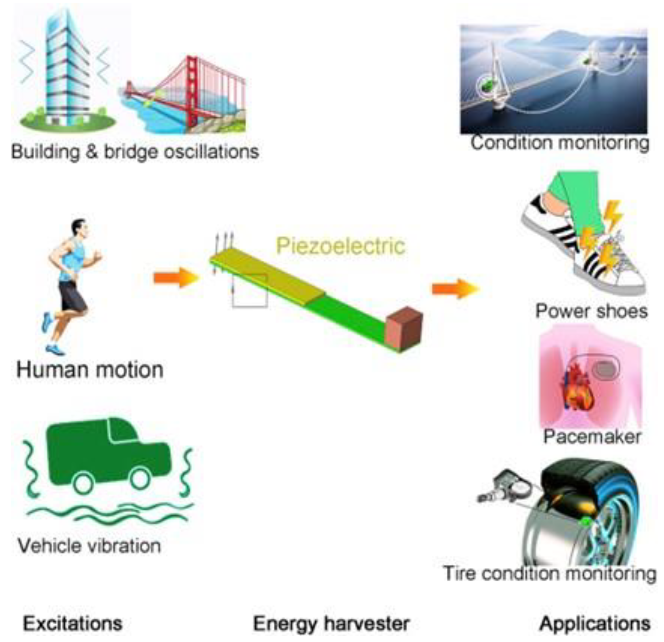
Figure 1. A typical energy harvesting operation’s process [1].
Energies 15 07424 g001
Figure 2. (a) Windmill with exciter teeth; (b) piezomagnetic windmill with no contact; (c) multi-magnet windmill with no connection [76].
Energies 15 07424 g002
Figure 3. (a) Testing of three propellers with different pitch angles; (b) pictorial view of rectangular piezoelectric windmill; (c) schematic of optimized three-fan blades in rectangular piezoelectric windmill; (d) contactless piezoelectric wind-turbine schematic featuring magnetically driven piezoelectric elements; (e) unregular piezoelectric wind-turbine schematic with parallel and circular configurations [83].
Energies 15 07424 g003
Figure 4. (a) Wind speed for the piezoelectric windmill with the variation in power; (b) at a wind speed of 40 m/s, measured voltage and power vs. external load using Series 1 and 2 cantilevers, with index “short” indicating L/D = 2.125 and “long” showing L/D = 5.057 [83].
Energies 15 07424 g004
Figure 5. Schematic of an airfoil going through model convergence flutter.
Energies 15 07424 g005
Figure 6. (a) Airfoil-based hybrid harvester; (b) T-shaped harvester; (c) electric current induction having a magnetic field in the flutter mill.
Energies 15 07424 g006
Figure 7. (a) Schematic of galloping with an energy harvester square bluff body; (b) at low wind speed, power enhancement through 2DOF piezoelectric galloping energy harvester [128].
Energies 15 07424 g007
Figure 8. Example of PEH-based Galloping [134].
Energies 15 07424 g008
Figure 9. (a) Comparison of vortex pressure in the cylindrical bluff body wake; and (b) associated pressure difference; (c) when a vortex is present in the cubical bluff body wake; and (d) associated pressure difference [148].
Energies 15 07424 g009
Figure 10. (a) Fluttering flag; (b) piezoelectric sectioned fluttering flag.
Energies 15 07424 g010
Figure 11. Duplet tandem PEH flow field scattering for different W/D and water velocity: (a) dispersion of the flow field at W/D = 3.33, U = 0.19 m/s; (b) flow-field dispersal at W/D = 3.33, U = 0.41 m/s; (c) flow-field dispersal at W/D = 3.33, U = 0.19 m/s; (d) flow-field dispersal at W/D = 8.33, U = 0.41 m/s [198].
Energies 15 07424 g011
Figure 12. Changes in upstream as a result of water velocity, harvester output power, and vortex-formation frequency and separation ratio: (a) water velocity and spatial ratio influence output power; (b) upstream harvester vortex shedding frequency as a result of water velocity and separation ratio [199].
Energies 15 07424 g012
Figure 13. The von Mises spread of stress (MPa) of the armored (2 mil steel) QuickPac (QP21B) leading stainless steel sheet: (a) sectional view; (b) at point force of 1 N; (c) displays curved stress, pointer movement, and the top piezoelectric surface of QP21B’s open-circuit voltage using the route illustrated in (a) [200].
Energies 15 07424 g013
Figure 14. The von Mises stress dispersion of armored QP21B with no need for a stepped joint; (a) over stepped-jointed armored QP21B; (b) a raised junction has a similar thickness as the shielding layer of stainless steel (t = 0.0508 mm) [200].
Energies 15 07424 g014
Figure 15. Experiments with a floating elastic device attached to a vertical marine cliff.
Energies 15 07424 g015
Figure 16. Elastic floating unit with hanging structure: (a) single device; (b) aggregated structure.
Energies 15 07424 g016
Figure 17. Energy-harvesting buoy schematics [210].
Energies 15 07424 g017
Table 1. Piezoelectric Devices in Wind Flow.
Windmill and Wind Turbine Energy Harvesting Devices
Sr No.DeviceTransducer Type Power   Density   ( mW / m m 3 ) DimensionsCut-In Wind Speed (m/s)Cut-Out Wind Speed (m/s)Wind Speed (m/s)Relevant InformationReferences
1.Fan-type windmillPiezoelectric bimorph0.01042 114   mm   diameter   ×   60   mm   width ,   60   ×   20   ×   0.6   mm 3 each beam--4.47-[134]
2.Vane-type vertical windmillPiezoelectric bimorph7.38 × 10−696 × 107 × 66 mm3 generator, 178 mm vane diameter--4.47-[135]
3.Fan-type windmillPiezomagnetic generator
PZT-5A
-31 mm diameter0.9-0.9-[136]
4.Fan-type windmill using impact-induced resonancePiezoelectric unimorph
PZT ceramic
-31 mm diameter--Not specified (fan with the speed of 200 RPM rotation)-[137]
5.Contactless windmill, Savonius turbinePiezomagnetic generator1.9 × 10−7 165   ×   165   ×   229   mm 3 --4.02
  • Fabrication is easy.
  • Comparatively much less power than circular windmill.
  • Due to vibration phase of all bimorphs combined circuit can be used
  • Have enough space because of rectangular-array arrangement of transducers
[137]
6.Small-scale windmill and turbinePiezoelectric material.
Contact via mechanical stopper
0.00267 5.08   ×   11.6   ×   7.62   cm 3 2.16.25.4 [138]
Flutter Energy Harvesting Devices in Wind Flow
Sr No.DeviceTransducer Type Power   Density   ( mW / m m 3 )Wind Speed
(m/s)
Cut-In Wind Speed (Flutter speed) (m/s)Cut-Out Wind Speed (m/s)DimensionsRelative InformationReferences
1.Rigid flap with revolute jointBimorph_ PZT6.3 × 10−57.92.6- 283.7   ×   136   ×   0.9   mm 3 -[138]
2.The piezoelectric film with plastic extensionRectangular film
PVDF
0.0524   µ W / mm 3 2-- 22   ×   13   ×   0.2   mm 3 -[138]
3.Piezoelectric grassBimorph0.0038 11.5-- Four   101.6   ×   25.4   ×   0.406   mm 3 beams-[139]
4.Inverted flagPiezoelectric membrane0.003479-- 60   ×   120   ×   0.2   mm 3 -[139]
5.Modal convergence flutter with flat platePiezoelectricStiff host:
6.078
Compliant host:
4.696
Stiff host:
26
Compliant host:
25
Stiff host:
17.3
Compliant host:
15.2
Stiff host:
29
Compliant host:
29
Flat plate tip: span 6 cm, chord 3 cm, thickness 0.79 mm.
Cantilever :   7.6   ×   2.5   ×   0.0381   cm 3
  • Wind speed and intensity have decreased, reduced in strong host as opposed to a compliant host
  • In the conforming host architecture, the power peak is shifted toward lower wind speed
[139]
6.Dual cantilever flutterPiezoelectric0.84513 approx.3 approx.- Two   identical   cantilevers :   14.6   ×   2.54   ×   0.0254   cm 3 Efficient power generation with high operational wind speed[140]
Micro Scale Piezoelectric Wind Energy Harvesters
Sr No.TransducerMechanical MechanismSize (mm)Peak PowerVoltageWind Speed(m/s)Power Coefficient Cp (%)Normalized Power Density (μW × s/ (mm3 × m))References
1.PiezoelectricAeroelastic2 × 1.65 × 0.005 34 nW25 mW5.20.0120.39[140]
2.PiezoelectricRotational47 × 20 × 0.5613 µW13 V200 r/min--[141]
3.PiezoelectricAeroelastic75 × 20 × 0.0040.98 µW1.2 V3.90.0020.041[141]
4.PiezoelectricRotationalϕ = 537.5 mW5 V4.476.32-[142]
5.PiezoelectricAeroelastic23 × 4 × 0.1300.64 µW1.6 V15 3.4   ×   10 4 0.004[143]
6.PiezoelectricAeroelastic58 × 10 × 0.20230 µW4.3 V50.060.05[144]
7.PiezoelectricAeroelastic3 × 8 × 0.0352.27 µW965 mV16.30.0040.17[144]
8.PiezoelectricAeroelastic69 × 37 × 0.243.3 V1 mW28.10.81[145]
Macro Scale Piezoelectric Wind Energy Harvesters
Sr No.TransducerMechanical
Mechanism
Size (mm)VoltagePower PeakWind Speed(m/s)Power Co-efficient Cp (%)Normalized Power Density (μW × s/ (mm3 × m))References
1.PiezoelectricAeroelastic76.7 × 12.7 × 2.28.8 V155 µW6.70.090.01[145]
2.PiezoelectricRotationalϕ = 80, t = 170 80 mV2 µW14 2.4   ×   10 5 1.7   ×   10 7 [146]
3.PZAeroelastic90 × 10 × 0.612 V145 µW3.50.630.08[147]
4.PZRotational325 × 36.2 × 0.26730 V1.14 mW4.960.150.077[148]
Table 2. Techniques of PEH in Wind Flow.
Ref.TechniqueBrief TitleHighlightsAuthors
[149]VIVFlow-induced based on PEHUtilizing a one-dimensional approach to investigate the function of an adaptable piezoelectric cylinder, the produced powerXie et al.
[150]VIVTree-simulated piezoelectricFour cylindrical linear arrays connected to piezoelectric actuator were tested in the wind.Hobbs and Hu.
[151]VIVDesigning of fluid K.E harvesters The harvester was optimized using a cuboid-shaped bluff body and a 1 μ W output power.Wen et al.
[151]VIVAir conditioners containing piezoelectricA piezoelectric energy-harvesting system was offered based on VIV with a fin for use in turbulent airflow.Weinstein et al.
[151]VIVCylindrical extension on piezoelectric cantileversA wind-driven cylinder with a piezoelectric beam attached to the edge has been described as an energy harvester.Gao et al.
[151]VIVPiezoelectric analysis with non-uniformityInvestigating a piezoelectric cantilever ray connected to the radial cylinder subjected to nonuniform distribution structure.Dai et al.
[152]VIVFluidic energy with flexible beamBy the usage of flexible beam piezoelectric harvesting vibrational energy construct of VIV.Dunnmon et al.
[152]VIVCircular cylinder of VIVEnhancing the efficiency of dual-mass development compromises on a circular cylinder.Dunnmon et al.
[152]FlappingOscillations in the aeroelastic limit cycleIn a wind s velocity of 27 m.s-1, piezoelectric plates were put on a floppy sheet.Dunnmon et al.
[153]FlappingCross flow fluttering by the usage of wind harvestersWind energy was turned into electrical energy by a swinging leaf dependent on aeroelastic fluttering.Li et al.
[154]TIVTIV comprising of artificial piezoelectric grassTIV was studied using a piezoelectric grass and a variable structure model.Hobeck and Inman
[154]TIVTIV with a mathematical frameworkTIV force of a unimorph cantilever was given by scattered a computational model.Hobeck and Inman
[155]TIVMicromachined piezoelectric harvesting2W of energy is produced by a MEMS piezoelectric and a Helmholtz oscillator that includes a packed harvester.Matova et al.
[156]TIVUnsteady flows for piezoelectric Flexible piezoelectric cantilever beams were positioned in turbulent boundary layers to generate 0.06 W.Akaydin et al.
[156]TIVWake of a cylinderApplying piezoelectric beams, the greater Reynolds values were used to study the effects of radial cylinders.Akaydin et al.
[157]TIVTurbulent boundary layers in piezoelectric transducers In a turbulent boundary layer, several piezoelectric beams were examined.Goushcha
[158]FIVIn axial flows, the performance of piezoelectric flagsA nonlinear variant of the FIV was proposed for a moving plate in an axial flow using piezoelectric patches.Michelin and Doare.
[159]FIVPiezoelectric cantilever of T-shapedDepending on the aeroelastic oscillation, a T-shaped piezoelectric cantilever was demonstrated.Kwo
[160,161]FIVSingle piezoelectric generator of aerodynamicA piezo-aeroelastic energy harvesting system that depends on flutter was studied.Bibo and Daqaq.
[162]FIVAeroelasticity nonlinearity Piezoelectric transmission and airfoil form nonlinear investigation methods.Dowell et al.
[163]FIVPiezoaeroelastics analysis To prevent pressurized collapse of piezo-aeroelastic harvesters, a nonlinear model was investigated.Abdelkefi et al.
[164]GallopingLow-power sensors containing wind harvesters In an air velocity of 11.6 miles per hour, a galloping-based piezoelectric yielded a captured energy of moreover 50 mW.Sirohi and Mahadi.
Table 3. Piezoelectric Devices for Liquid-Fluid-Energy Harvesting.
DevicesTypes of TransducersGenerator MaterialDimensionsFlow CharacteristicsOutput PowerEnergy SourceReference
Piezoelectric-buoy harvesterTwo-stage buoy mechanismPDVF76.2 × 76.2 × 914.4 mm3-60–180 mWOcean Waves[186]
Energy harvestingBimorphPVDF240 × 76 × 0.150 mm30.5 m/s flow3 W-[186]
Transverse wave harvesterHorizontal bimorphPVD-42 cantilevers of 2.4 × 1 × 0.01 m3-30 W RMSTransverse ocean waves[187]
Fluttering flagBimorphPZT14 × 11.8 × 10.35 mm345 m/s flow0.1 mW-[187]
Rain harvesterUnimorphPVDF25 × 13 × 3 mm3-2.5 nWRain Drops[188]
Fluid fluctuation harvester with PVDFDiaphragmPVDF25 × 13 × 0.150 mm31.196 kPa pressure fluctuation at 26 Hz0.2 µW-[189]
Harvester with deep ocean waveBimorph-buoyPZT-42 cantilevers of 1 × 0.2 × 0.006 m3-24 W RMSTransverse ocean waves[189]
Fluid fluctuation harvester with PZTDiaphragmPZT8 × 3 × 0.200 mm320.8 kPa pressure fluctuation at 45 Hz0.45 nW-[190]
Hydraulic harvesterStackPZT6.8 × 6.8 × 30 mm3-1.2 mWHydraulic pressure[191]
Longitudinal wave harvesterVertical bimorphPZT-43 × 1 × 0.05 m3-55 W RMSLongitudinal ocean waves[192]
Tubular energy harvesterTubePZT-5A8 mm inner radius, 2 mm thickness, 20 mm length-0.1 WPressure inside tubes[192]
Energy harvestingCymbal transducerPMN-PT25 × 5 × 1 mm3-3.7 mW-[193]
Energy harvestingUnimorphPMN-PZT20 × 5 × 0.5 mm3-0.015 mW-[194]
Energy harvestingBeamPMN-PT7.4 × 2 × 0.1 mm3-7.18 µW-[195]
Cantilever leaf structure-Microfiber composite (MFC) piezoelectric2.8 × 1.4 × 0.03 mm37.5 m/s flow0.55 mW-[196]
Nested structure by piezoelectric gallopingBeamM2814P2 (MFC)180 × 10 × 0.8 mm32.1 m/s flow0.16 mWWind[197]
Table 4. Piezoelectric materials in water flow.
TechniqueBrief TitleHighlightsAuthors
EelEel-based harvestingThe initial study used an eel technique to create a flexible PVDF membrane (2001).Taylor et al., Allen and Smits
VIVBicylinder having MFC piezoelectric cantileverA bicylinder VIV piezoelectric harvester generated 21.86 W of power in water flow.Song et al.
VIVUsing PZT producing VIV from waterThe output power of a vertical cylinder harvester experiencing VIV from water flow was 84.49 W.Song et al.
VIVVibrational energy with piezoelectric transducers Piezoelectric transducers gathered energy from a tiny network’s fluid flow (2016).Hassan et al.
MicropumpNon-valve nozzleA pioneering piezoelectric mini pump with no valve was investigated (1993).Stemme
MicropumpPiezoelectric pump without valvesA piezoelectric pump having a dynamic model was proposed (2001).Ullmann et al.
MicropumpA dynamic model for pump without valvesA piezoelectric non-valve pump’s efficiency was improved (2002).Ullmann
MicropumpRing-type actuators in micropumps with valvesSimulation of piezoelectric valveless systems is rather comprehensive, so a
micro-pump was used (2006).
Zhang and Wang
MicropumpMicropump having a circular actuatorFor a circular piezoelectric micro-pump operator, the FE approach was examined (2000).Morris and Forster
MicropumpMicropump diaphragm containing polymerA PVDF-TrFE microfluidic pump was studied (2005).Xu and Su
MicropumpMicrofluidic electroactive pumpA PVDF-TrFE micro-pump with an actuator was investigated (2006).Xia et al.
MicropumpPrinted piezoelectric inkjetFor PVDF-constructed transducers, an all-inkjet-printed piezoelectric polymer method was developed (2013).Pabst et al.
VIVWater vortex containing MFC piezoelectricYielded 1.32 watts of power by water-induced vibration utilizing an MFC piezoelectric.Shan et al.
EelAxial flow cantilevered bendable panelsFlutter-mill analytical modeling was used to harvest fluid flow’s electrical energy (2009).Tang et al.
VIVWater way with microscale piezoelectricThe extremity of a bluff body was fitted with a flexible piezo-film transducer.Koyvanich et al.
Table 5. Energy Harvesting Strategies.
Energy SourceHarvesting StrategyMaterialCoupling Mode
Water CurrentFlow-induced vibrationPVDF3-1 mode
Wave MotionTilting and heaving of bodiesPZT3-3 mode
Bodies anchored to the ocean bedPVDF/PZT3-1 mode
Ocean surfaces with adjustable membranePVDF3-1 mode
Resultant Forces of WavesSplashingPVDF3-3 mode
Table 6. Extractors of Piezoelectric Materials from Ocean Waves.
Ref.Short TopicsIllustrationAuthors
-Piezoelectric windmill simulationThe piezoelectric windmill pattern used the frequency up-conversion technique (2005).Priya
[211]Oceanic wave-energy transducersThe frequency up-conversion approach was used to construct WEC system piezoelectric vibrators (2011).Zhang and Lin
[212]In the converters for ocean-wave energyLow-cost disc piezoelectric components have been used in the WEC device (2013).Vinolo et al.
[213]Conversion of ocean-wave energyA line of piezoelectric micro-thin sheets was used in a wave-power harvester (1987).Burns
[214]Harvesting energy from transverse ocean wavesConnected to the piezoelectric marks is a cantilever (2014).Xie et al.
[214]The piezoelectric potential for marine wavesA vertical cantilever column was installed on the seabed with piezoelectric patches attached (2014).Xie et al.
[215]Oceanic wave-energy harvestingA cost-effective solution for oceanic piezoelectric wave-energy harnessing was given (2015).Wu et al.
Publisher’s Note: MDPI stays neutral with regard to jurisdictional claims in published maps and institutional affiliations.