Abstract
This paper presents the reverse hinge spoiler, a novel spoiler concept, for flight load control. The reverse hinge spoiler is a control surface mounted on the upper surface of the wing. Unlike conventional hinged spoilers that are hinged at their front and rotate forward toward the leading edge of the wing, the proposed spoiler concept is hinged at its rear and rotates backward toward the trailing edge of the wing. The aerodynamic performance of the proposed spoiler is compared and contrasted with that of a conventional hinged spoiler for different flight conditions and hinge locations using the two-dimensional Reynolds-Averaged Navier–Stokes (RANS) with the k-omega SST turbulence model-based computational fluid dynamic solver. The results show that the proposed spoiler results in a larger increase in drag and a sharper reduction in the lift for a wide range of spoiler angles and flight conditions. Reversing the spoiler is found to cause a higher adverse pressure gradient in front of the spoiler compared to a conventional spoiler, as it ‘traps’ more flow, thereby increasing drag and reducing lift.
1. Introduction
Conventional hinged spoilers are used widely on all different types of modern aircraft, ranging from small UAVs and gliders to large airliners. They are control surfaces mounted on the upper surface of a wing. When the spoiler is deflected, it ‘spoils’ the smooth flow on the surface, causing a reduction in lift and an increase in drag. The use of spoilers varies widely and is dependent on where they are located and how they are deployed. They can be categorized into two different types: Ground Spoilers and Flight Spoilers. Ground Spoilers are deployed upon landing, or after an aborted take-off, symmetrically at high deflection angles, to reduce the speed of the aircraft. This retardation is amplified in two ways. A large increase in drag on an aircraft allows it to reduce its velocity rapidly before reaching the end of the runway. This reduction in lift, termed ‘lift dumping’, results in a higher fraction of the aircraft weight to be carried by the landing gear, resulting in more effective braking and a shorter landing distance. On the other hand, Flight Spoilers are used throughout the flight to provide the necessary control of the aircraft. When deployed symmetrically at controlled angles of attack, they can be used for direct lift control applications [1], allowing an aircraft to increase its descent rate without increasing speed. When deployed asymmetrically, spoilers can be used either to augment or substitute ailerons with the lateral (roll) control of the aircraft. Spoilers are preferred at high dynamic pressures, where the deployment of the ailerons can cause the wing to twist excessively, which not only reduces the lateral control expected but, in certain conditions, can cause the control response from the aircraft to be reversed to what is expected (control reversal). In general, spoilers can be rapidly deployed, and have a preferable yawing moment and lower changes in pitching moment compared to ailerons [2, 3]. Spoilers can also provide active control for flutter suppression [4], enhancement of the passenger ride during turbulence, and gust load alleviation [5]. Multiple studies were conducted by NACA to understand how spoiler devices can be used for lateral aircraft control [1,2,3]. These studies aimed to obtain satisfactory stability and controllability throughout the entire range of speed or the angle of attack. Flight tests [4] defined the required flight characteristics, with a key requirement being immediate aircraft response when spoilers are used for roll control. Weick et al [6] performed in-flight tests to investigate the characteristics of lateral control devices: a forward-mounted spoiler, a forward-hinged spoiler, a rearward-hinged spoiler, and a retractable spoiler. The lag between the control input and aircraft response was plotted and showed that forward-mounted spoilers had an appreciable lag from input to response when compared to ailerons. As deduced by Harley [2], a possible explanation for this is due to the separated flow downstream of the spoiler changing the surface pressure. Therefore, to counter this time lag, a possible solution would be to move the spoiler more rearwards. From this point onwards, the trend of investigating rearward-mounted spoilers continued with Wentz et al. [7] and McLachlan et al. [8], investigating the effectiveness of spoilers on a Boeing research airfoil. The spoiler height was set to 0.15C whilst the hinge line was located at 0.733C. From this study, it was found that as the spoiler is deflected, the change in lift between the airfoil with the spoiler compared to that without a spoiler increases, highlighting the spoiler’s effectiveness. There have also been numerous computational and experimental studies [9,10,11,12,13,14,15,16,17,18,19] investigating the effect of spoiler position, spoiler deflection angle, and spoiler chord on the aerodynamic characteristics of different airfoil geometries. Mashud et al. [9] investigated a NACA2415 airfoil equipped with spoilers located at 0.5C, 0.6C, 0.7C, 0.8C, and 0.9C to determine the spoiler's effectiveness. It was found that moving the spoiler more downstream leads to a later stall angle, most likely due to the flow remaining attached for longer. All cases equipped with spoilers resulted in lower lift production and increased drag production compared to those without a spoiler. Lee et al. [10] investigated experimentally the flow field of an airfoil with the deflected spoiler at low speed and found that the base pressure behind the spoiler changes rapidly with the angle of attack, and the location of the hinge bubble depends on the boundary layer characteristics, angle of attack, and spoiler deflections. Furthermore, Kalkanis [11], Geisbauer [12], and Alhawwary et al. [13] analyzed numerically (using a discrete vortex method, an in-house steady RANS solver, and a higher-order spectral difference method, respectively) the flow-fields around an airfoil with a deflected spoiler, in which the pressure distribution, spoiler wake, and vortex-shedding behavior were investigated. They found that the typical vortex shedding behavior of a spoiler was similar to that of bluff body shedding. The flow field was characterized by a highly turbulent fluctuating wake, and the strength of the wake increased with a spoiler deflection angle [13,14]. Askar et al. [15] investigated numerically, using Ansys14 software, the effect of the spoiler position, and the gap between the spoiler and wing. They found that at a gap of 0.0333C, spoiler position of 0.5C, and spoiler chord of 0.1C, there was a drop of 28.3% in lift compared to the clean wing. In terms of spoiler length, detailed parametric studies into the effect of spoiler length have not been investigated. Lindsay [16] did, however, conduct an experimental study comparing a 0.1C-long spoiler to a 0.15C-long spoiler, concluding that, at the same angle of attack, the 0.15C spoiler reduced the lift coefficient by 1.7% when compared to a clean airfoil. This could be explained by the larger projected area of the longer spoiler increasing the friction drag and causing earlier separation.
Recently, some research on the aerodynamics of static and dynamic spoiler deflections has been conducted. Tian et al. [17] used a RANS method in steady and unsteady mode to investigate the potential of small spoiler deflections for buffet control on an airfoil and a wing, showing that small spoiler deflections could reduce the oscillation amplitudes at buffet onset. Geisbauer et al. [18] presented wind tunnel tests on a static and dynamic airfoil–spoiler system conducted at the German Aerospace Centre (DLR) facilities, to validate and verify an in-house DLR numerical flow solver. For the statically deflected spoiler, the results obtained are in good agreement with previous studies. For the dynamic spoiler deflection, it was observed that adverse lift was induced for all the spoiler deflection angles tested (10 degrees, 30 degrees, 50 degrees, and 70 degrees) and that the deflection rate of the spoiler has no significant influence on the spoiler’s efficiency with respect to the induced lift loss. Further numerical simulation and validation of the aerodynamics of static and dynamic spoilers have been done by Geisbauer [19] by extending the application range of DLR’s in-house flow solver TAU.
To conclude this section, it can be seen that in terms of spoiler position, spoilers placed more rearwards are favorable. Similarly, spoiler chord length has not yet been widely investigated; however, the majority of papers in the literature tend to use spoilers of lengths 0.1C to 0.15C. Conventional hinged spoilers have been used since 1948 and are still in widespread use today, proving how successful they are. However, despite how common they are, there has been limited development around improving the performance of these spoilers since. This paper aims to develop a novel reverse hinge spoiler concept whose performance is superior to conventional ones. Detailed 2D CFD studies are conducted to compare and contrast the performance of the proposed spoiler to that of the conventional one at a wide range of flight conditions and design parameters. The superior performance of the proposed spoiler allows for reducing its size, which can result in considerable weight and actuation power savings.
2. The Reverse Spoiler Concept
Contrary to a conventional spoiler (Figure 1a), the reverse hinge spoiler is hinged at its back and rotates towards the trailing edge of the wing, as shown in Figure 1b.
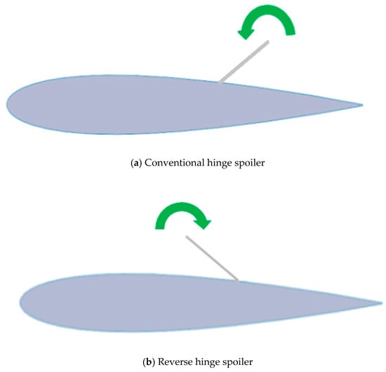
Figure 1.
Conventional spoiler and the reverse hinge shark teeth spoiler.
3. Computational Fluid Dynamics
To compare the performance of the conventional spoiler and the reverse hinge spoiler, a two-dimensional CFD investigation was carried out on various spoiler configurations. In this study, a NACA0012 airfoil section was used as it is a symmetric airfoil with zero camber, simplifying the analysis to spotlight the focus on the effect of the spoiler only. The numerical flow simulations were conducted using ANSYS FLUENT. The steady RANS k-omega SST model was used. The k-omega SST turbulence model was adopted here as it offers improved predictions of flow separation under adverse pressure gradients [20]. Even though the flow around a spoiler is inherently an unsteady problem due to the rapidly changing wake behind the spoiler and the abundance of vortical motion caused by the spoiler, studies have shown that steady simulations compare fairly to experimental testing when comparing the main flow coefficients and local pressure distributions of the conventional spoiler [16,21].
3.1. The Mathematical Model
In the present work, the incompressible viscous flow around the spoiler is described by the RANS equations, and is given by the continuity Equation (1) and the momentum Equation (2), as follows [22]:
where 𝑡 is time; 𝑢𝑖 and 𝑢𝑗 are the time-averaged velocity components, respectively; 𝜌 is the density of the fluid; and , where is the time-averaged pressure, is the turbulent kinetic energy, 𝜇 is the dynamic viscosity of the fluid, and is the turbulent or eddy viscosity of the fluid. The equations describing the turbulence kinetic energy and its specific rate of dissipation for the k-omega SST turbulence model are as follows [23]:
where represents the generation of turbulence kinetic energy; represents the generation of ; represents the cross-diffusion term; and represent the effective diffusivity of and , respectively; and represent the dissipation of
and due to turbulence, respectively; and and are the user-defined source terms. For more details on these variable definitions, the reader is advised to check [23].
3.2. Spoiler Variables
For the investigation, three main spoiler variables can be changed (Figure 2):
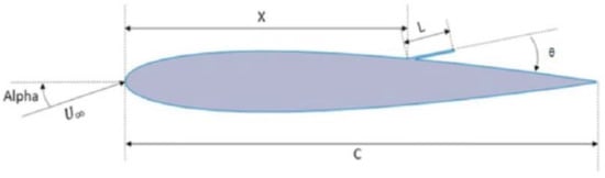
Figure 2.
Spoiler–airfoil variables.
- Non-Dimensional Spoiler Length, L/C;
- Non-Dimensional Hinge Location of the Spoiler, X/C;
- Spoiler Deflection, θ (relative to a tangent drawn on the airfoil surface).
To decide the values for the different variables, the initial review (Section 1) was used to highlight a suitable range of values for each variable. This was based upon factors such as where spoilers are commonly situated on wings and the structural implications alongside where spoilers perform optimally. The spoiler configurations that were studied here are tabulated below (Table 1). For each change in a spoiler variable, this change was kept constant whilst running through the rest of the possible configurations for the other variables; e.g., a 5-degree spoiler angle was tested at a spoiler length of 0.1 and 0.15C, and both of these were tested at all hinge locations (0.6 and 0.7C)—four unique configurations.

Table 1.
Spoiler configurations.
This led to a total of 40 different configurations when including both the reverse and conventional spoilers.
For each of these configurations, the simulations were run through a range of airfoil angles of attack (0, 3, 6, 9, 12, 13, 14, and 15 degrees). The angles of attack highlighted in bold are the region where stall occurs; hence, convergence in these areas was of greater difficulty. It should be noted that the operating range for the spoilers is usually below these angles.
3.3. Geometry
To ensure the 2D CFD was comparable between the reverse hinge and conventional hinge spoiler, a parametric CAD model was developed, capable of producing any of the required geometries needed for both types of spoiler. The configurations were then imported into ANSYS Fluent. The spoiler itself consisted of a simple flat plate with a blunt tip, as shown in Figure 3. The airfoil chord, spoiler deflection, spoiler hinge position, and spoiler length can all be altered as desired with the hinge position and length being determined as a percentage of the total wing chord. By changing the spoiler deflection angle to past 90 degrees (where the reverse and conventional are equivalents), it would produce geometries for the reverse hinge spoiler; e.g., a spoiler deflection of 165 degrees would represent a 15-degree reverse hinge spoiler deflection.
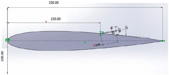
Figure 3.
Parametric spoiler–airfoil geometry.
3.4. Mesh Generation and Boundary Conditions
For mesh generation, several choices around the configuration were considered and it was found that an unstructured hybrid mesh with triangular and rectangular elements was suitable, and thus has been used in all 2D CFD cases. An inflation layer was used up to 0.15C from the airfoil surface, which allowed the tuning of the (with) through changing the first layer height whilst also ensuring accurate capture of the boundary layer. The inflation layer was projected downstream by 1C to capture the wake. A mesh refinement region was used around the vicinity of the spoiler where a high density of cells was placed to capture the interaction between the spoiler and the incoming flow. Away from this region, an unstructured triangular mesh was used.
For the boundary conditions, the upstream boundary was set as the velocity-inlet condition, while the downstream boundary was set as the pressure outlet. For the airfoil–spoiler-related surfaces, a solid wall no-slip boundary condition was applied. For the upper and lower boundaries, the free-stream velocity condition was imposed.
3.5. Grid Independence and Verification Analysis
The grid independence was carried out by increasing the number of elements within the same domain. The mesh was made finer at points of interest, such as around the spoiler, airfoil surface, as well as both the LE and TE, to capture the stagnation point and the wake. Focusing on these areas of importance eliminated the need for there to be a very fine base cell size, which encompassed the majority of the domain. Again, this would save computational time, and therefore environmental implications were once again taken into consideration. The size of the wake region was initially identified by viewing the contours of Turbulent Kinetic Energy on an initial simulation. Most of the disturbed fluid developed downstream of the spoiler; therefore, observing where the intensity of the Turbulent Kinetic Energy started to diminish produced an indication as to what size the wake region should approximately be. Thus, this region within the mesh was refined to be made finer and was also extended as it was acknowledged that at higher spoiler angles the wake would be expected to be more substantial. The mesh independence study was carried out on the setup that would contain the greatest cell count—a spoiler size of 0.1C, deployed at 90 degrees. This was so that the mesh that eventually would be chosen would be mesh-independent for all configurations; thus, not just smaller spoilers and those that are deployed at lower angles. The lift and the drag coefficients were obtained using the RANS k-omega SST turbulence model with the SIMPLE (semi-implicit method for pressure-linked equations) algorithm used for pressure–velocity coupling, and second-order schemes for pressure, momentum, and turbulence. From Table 2 and Figure 4, it can be seen that the percentage differences between CL and CD decrease as the mesh is refined, and it is less than 1% when the number of cells is more than 312,000. Beyond a cell count of 312,000, however, the change was much more negligible where the increase in CD and decrease in CL was less than 1%. This was taken to be the default mesh that was to be used for the 2D analysis.
Table 2.
Mesh independency (variation in CL and CD vs. cell number) for NACA0012.
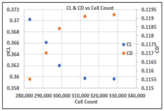
Figure 4.
Variations of CL and CD with cell number for NACA0012.
Grid Uncertainty Analysis
To estimate the numerical uncertainty associated with the grid refinement error, the grid convergence index (CGI) methodology was used. The GCI method, proposed by Roache [24], is widely used and was recommended, e.g., by the ASME (American Society of Mechanical Engineers) V&V 20 Committee [25]. Using the orders of convergence of the lift and drag coefficients, the GCI can be calculated between mesh resolutions. The equation to compute the grid index is given in Equation (5) below. Throughout these calculations, a safety factor of 1.25 is applied since three meshes were considered [26].
where is the error between the grid, given as for the fine and medium mesh and for the medium and coarse mesh; is the order of convergence, and is the grid refinement ratio. Here, can be or . To investigate the asymptotic convergence of the solutions, the GCI can be computed using three refinement levels. The two refinement levels used for the calculation were selected from Table 2 (i.e., N1 = 282992 and N2 = 328078 elements). For the third mesh (fine one), the solver was run with N3 = 1120226 elements and the results were obtained as = 0.3594 and = 0.1194. Since an unstructured grid is utilized here, the effective grid refinement ratio is calculated using Equation (6) [26].
where is the dimension of the flow domain. Using the values of and , we found . The order of convergence p can be obtained using the formula Using Equation (5), the GCI between meshes can be calculated. A value of = 0.001% for the fine and medium mesh and for the medium and coarse mesh was determined for the lift coefficient and a = 0.012% for the fine and medium mesh and a of 0.22% for the medium and coarse mesh for the drag coefficient values. The GCI results for and from the three different meshes show good decremental values from to (i.e. ). These results show that the dependency of the numerical method on the mesh size decreased when the GCI for the fine grid is lower than the coarser grid ( Thus, the results of the simulation will not be of much difference as further grid refinement is changed. After determining the grid convergence index, the solution needs to be checked using Equation (7), as it is within the asymptotic range of convergence. This yields a value of 0.9994 for the lift coefficient and 0.9798 for the drag coefficient, which both approximate 1, satisfying Equation (7).
3.6. Validation
To ensure the mesh and physics are adequate to capture the flow separation from the spoiler, comparisons were made to existing data. The meshing strategy detailed in Section 3.3 was validated against two cases: a clean NACA0012 airfoil (without a spoiler) and a NACA2412 airfoil with a conventional spoiler. Table 3 shows the mesh and flow parameters. Results for the first case are presented in the form of force coefficient data and then compared to the XFOIL panel method [27] results, while for the second case results are presented in the form of pressure coefficient data along the surface of the airfoil and compared to the experimental data [16].
Table 3.
Validation cases.
3.6.1. Clean NACA0012 CFD Results Validation with XFOIL
The NACA 0012 case was chosen to demonstrate our meshing strategy's ability to predict force coefficients. The domain/faces and the mesh used for the CFD simulations are shown in Figure 5. Figure 6 shows the lift and drag coefficients data with XFOIL’s results for comparison, for a range of angle of attacks and Re of 166,023. As can be seen from these figures, the lift and drag coefficients obtained from the CFD results showed a good correlation to the XFOIL data before the stall angle.
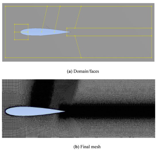
Figure 5.
Airfoil–spoiler: domain/faces and final mesh used for the validation study.
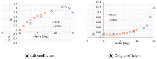
Figure 6.
Lift and drag coefficients versus angle of attack of clean NACA0012 using CFD and XFOIL.
3.6.2. NACA 2412 with a Conventional Spoiler CFD Validation by Experiment
The flow around an airfoil mounted with a conventional spoiler was investigated experimentally by Lindsay and Walsh [16]. A NACA2412 airfoil was used with the spoiler deflected to 8 degrees. Reynold’s number with respect to the chord was 783,761. The mesh used for this validation case is shown in Figure 7. It can be seen that mesh refinement has been placed within the vicinity of the spoiler to capture the complex flow features, including separation, whilst the refinement downstream of the airfoil is used to capture the wake. The boundary layer is resolved by choosing a dimensionless wall distance of on the entire geometry.
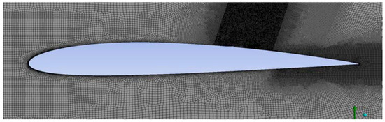
Figure 7.
Final mesh of the NACA2412 airfoil–spoiler used in this validation study, with a refinement region around the spoiler and wake.
Figure 8 shows the pressure coefficients for the CFD results and experimental data [16] at low and high angles of attack for the NACA2412 conventional spoiler configuration. From these figures, it can be seen that the 2D CFD results obtained for the pressure distribution along the surface of the airfoil agree well with the experimental data [16]. The maximum errors between the CFD results and the experimental data for Figure 8 are found to be 5.93% and 9.34%, respectively; however, most CFD values are within 1% error or less of the experimental data.
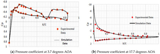
Figure 8.
Comparison of pressure coefficients of NACA 2412 (with conventional spoiler) with experimental data [16] at different angles of attack.
4. Conventional vs. Reverse Hinge Spoilers—Performance Analysis
The performance of a NACA0012 airfoil with conventional and reverse hinge spoilers was investigated, and a comparison between these two spoilers was done over a range of spoiler hinge locations, spoiler angles (deflection), spoiler lengths, and angles of attack, to investigate the performance over a wide range of potential configurations.
4.1. Effect of Spoiler Hinge Location
The effect of altering the hinge location/position of the spoiler was investigated for both the conventional and reverse hinge configurations. Two different spoiler locations were used (0.6C and 0.7C, which are representative of spoiler hinge locations in the standard aircraft), and were normalized with respect to the chord of the wing. To compare exclusively the impact of hinge location, a representative spoiler configuration was used, which best highlighted the trend (60-degree and 25-degree spoiler deflections, and 0.15C spoiler length). Figure 9 and Figure 10 show the effect of the hinge positions on the value of the lift and drag coefficients, respectively, for both the conventional and reverse spoiler configurations for the 60-degree deflection and 0.15C spoiler length, and at different locations (0.6C and 0.7C). From these figures, it can be seen that both the conventional and reverse spoilers show a similar trend, where at a low angle of attack (e.g. 0-degree), aft hinge positions correlate to a slight decrease in lift coefficient compared to the forward hinge positions and this is consistent throughout all the different spoiler configurations. Although, as the angle of attack is increased, this trend switches completely with the forward hinge positions, reducing the lift by more than the aft hinge positions, which is consistent with the literature [7,8]. For the drag coefficient (Figure 10), the trend is simpler where the forward hinge positions increase the drag by more than the aft hinge positions throughout the entire angle of attack range.
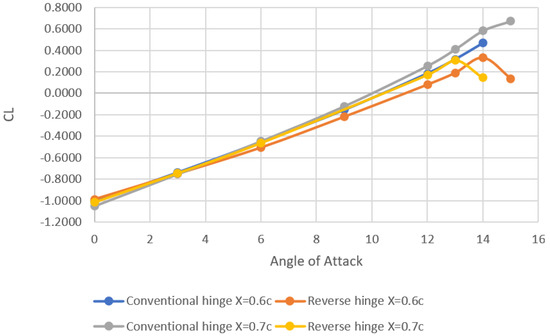
Figure 9.
Effect of spoiler hinge location on the lift coefficient for a conventional and reverse spoiler at a 60-degree spoiler deflection and spoiler length of 0.15C.
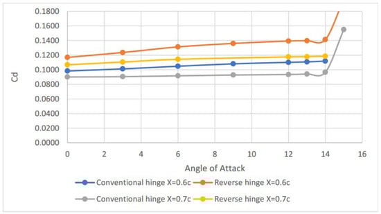
Figure 10.
Effect of spoiler hinge location on the drag coefficient for a conventional and reverse spoiler at a 60-degree spoiler deflection and spoiler length of 0.15C.
Flow-Field Analysis
Figure 11 gives more insights into the pressure coefficients for the conventional and reverse spoilers at 0- and 12-degree angles of attack, 60 degrees of deflection, and at different locations (0.6C and 0.7C). From these plots, it can be seen that the reverse spoiler follows the same trend as the conventional spoiler, and at the spoiler location (X/C = 0.6 and X/C = 0.7), the spoiler created a large discontinuity in pressure on the upper surface, as expected. For an angle of attack of zero degrees, the pressure coefficient on the lower surface stays roughly constant throughout and there is a small change/increase in the upper surface pressure before the spoiler depending on the hinge position (Figure 11a,b)). However, this increase in pressure forward of the spoiler (Figure 12a) does not outweigh the increased area on which the pressure can act for the aft spoiler position (Figure 12b); the aft hinge position reduces the lift by more.
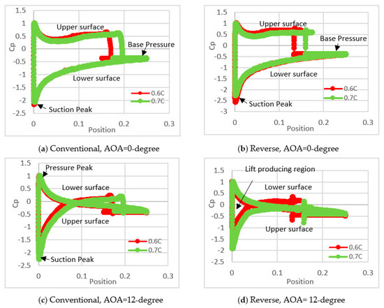
Figure 11.
Pressure coefficients for the conventional and reverse spoilers at locations 0.6C and 0.7C for 0- and 12-degrees angle of attacks, and a deflection angle of 60 degrees.
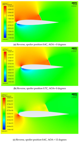
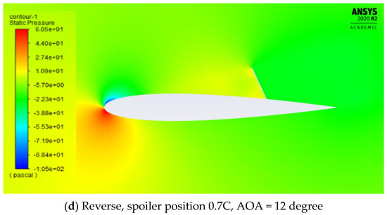
Figure 12.
Static pressure contours of the reverse spoiler at hinge positions 0.6C and 0.7C, for a 60-degree deflection angle and 0- and 12-degree angles of attack.
At a higher angle of attack (Figure 11c,d)), the direction of the incoming flow changes, which moves the leading edge stagnation point further onto the pressure surface of the airfoil where now the lower surface has a pressure peak and the upper surface has a suction peak. Since the flow is accelerating around the leading edge onto the top surface, this causes a lower pressure on the suction surface. This low-pressure region changes to a high-pressure region much faster when the spoiler position is further forward along the chord, which is why the forward spoiler position is more effective at high angles of attack. For the aft hinge position spoiler, despite having a bigger area for the pressure (Figure 12d) to act over, this is offset by the higher-pressure region formed in front of the forwardly placed spoiler (Figure 12c).
Figure 13 shows the velocity contours for the reverse spoiler at the 0.6C and 0.7C hinge positions for 0- and 12-degree angles of attack and a deflection angle of 60 degrees. There are two main regions of separation: the hinge bubble, which is located just ahead of the spoiler hinge position and encompasses the lower region of the spoiler; and the large separation behind the spoiler, which originates from the spoiler tip and emanates from the aft of the spoiler as a free shear layer in the wake of the spoiler, resulting in a drastic decrease in lift. As this separation stays completely detached from the airfoil surface, an approximately constant base pressure is formed (Figure 11b,d). At a 0-degree angle, the forward spoiler induces a larger separation behind the spoiler at the upper surface and, as such, there is an increase in drag (Figure 13a) compared to the aft spoiler (Figure 13b). Looking at Figure 14b, it can be seen also that the aft spoiler has a larger size of the separation bubble (Figure 14b) in front of the spoiler in comparison to the forward spoiler (Figure 14a), thus reducing the suction pressure, or increasing the pressure, on the upper surface, which leads to a lower lift. At a high angle of attack (12 degrees), the velocity contour (Figure 13c) shows that for the forward spoiler (hinge position 0.6C) the flow separates earlier with a sharper separation behind the spoiler, and a larger hinge bubble (Figure 14c), and as such, there is an increase in drag, and a reduction in the lift in comparison to the aft spoiler (hinge position of 0.7C, Figure 11d and Figure 14d).
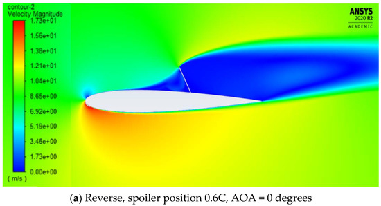
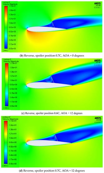
Figure 13.
Velocity magnitude contour of the reverse spoiler at hinge positions 0.6C and 0.7C, for a 60-degree deflection angle and 0- and 12-degree angles of attack.
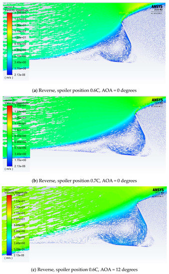
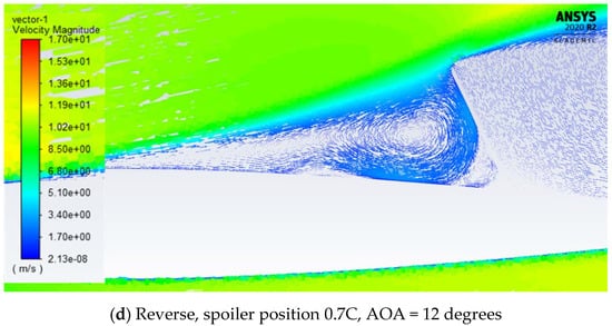
Figure 14.
Velocity vectors around a reverse spoiler at hinge positions 0.6C and 0.7C, for a 60-degree deflection angle and 0- and 12-degree angle of attacks.
Figure 15 compares the pressure coefficients of the conventional and the reverse spoilers at the same spoiler position (0.6C), a 60-degree deflection angle, and an angle of attack of 6 degrees. This figure shows that the reverse hinge has a sharp drop-off in pressure coefficient (vertical drop) upon separating around the spoiler, unlike the conventional case. The reason for the increase in pressure for the reverse hinge can be thought of as the reverse hinge essentially ‘trapping’ the flow (Figure 16b) due to the spoiler being directed back upstream into the flow. The increase in pressure at the upper surface and the decrease in pressure at the lower surface for the reverse hinge (Figure 15), in comparison to the conventional hinge, caused a further loss in the lift for the reverse hinge. The increase in drag for the reverse spoiler is due to the higher induced pressure in front of the reverse spoiler (Figure 15 and Figure 16b). As the pressure behind the spoiler is fixed to a base pressure, this means there is a larger pressure difference upstream and downstream of the spoiler, increasing the pressure drag.
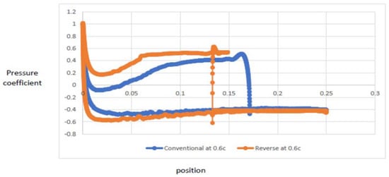
Figure 15.
Pressure distribution comparison between the conventional and the reverse spoiler at a hinge position of 0.6C, a 60-degree deflection angle, and a 6-degree angle of attack.
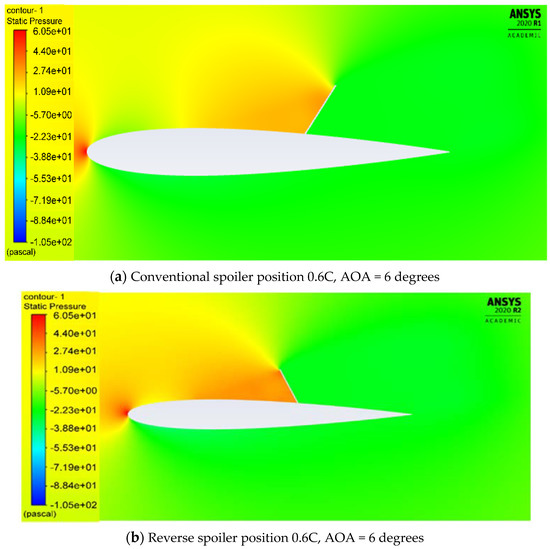
Figure 16.
Static pressure contours for the conventional and reverse spoilers at a 0.6C hinge position, 60-degree deflection angle, and 6-degree angle of attack.
Figure 17 and Figure 18 show the results for the lift and drag of the conventional and reverse spoilers for the 0.6C and 0.7C hinge positions at a lower deflection angle of 25 degrees. As can be seen from these figures, the forward-reverse spoiler (0.6C) has a substantial reduction in lift and a greater drag increase overall in the angles of attack in comparison to the aft spoilers (both conventional and reverse) and forward conventional spoiler (0.6C).
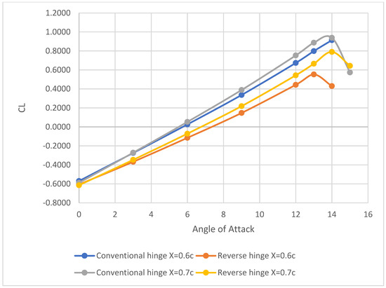
Figure 17.
Effect of spoiler hinge location on the lift coefficient for a conventional and reverse spoiler at a 25-degree spoiler deflection and spoiler length of 0.15C.
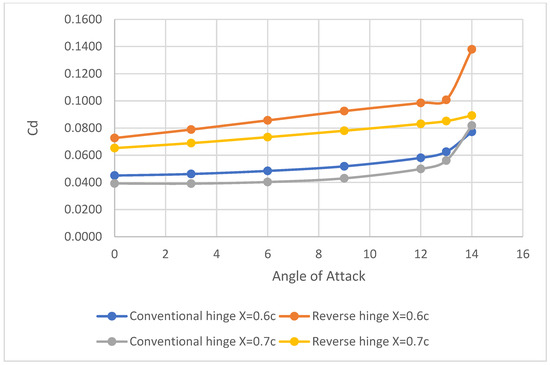
Figure 18.
Effect of spoiler hinge location on the drag coefficient for a conventional and reverse spoiler at a 25-degree spoiler deflection and spoiler length of 0.15C.
4.2. Effect of Spoiler Deflection
Figure 19 shows the variation in the lift-drag polar over a range of different spoiler deflections for the conventional and reverse hinge spoilers for a representative spoiler configuration (0.6C spoiler position, 0.15C spoiler length) and the 90-degree spoiler angle test case, which have identical geometries for both spoiler types. The effect of spoiler deflection can be thought of as how the lines spread out from each other. As they get more positive on the y-axis, the more effective the spoiler deflection is at increasing drag, and as they become more negative on the x-axis, this corresponds to greater effectiveness at dumping lift. Generally, the trend we see is similar to that found in the literature [2] for the conventional spoiler. For low spoiler deflection angles (5–25 degrees), the drag polar plots for the conventional case are closer together than compared to the reverse hinge case. The gradient for the reverse spoiler is also larger through the angle of attack range, which corresponds to increased effectiveness over the conventional spoiler at higher angles of attack. At a 60-degree spoiler deflection, the reverse hinge is much closer to the 90-degree case than the conventional spoiler, mainly in the y-direction, indicating a large difference in drag.
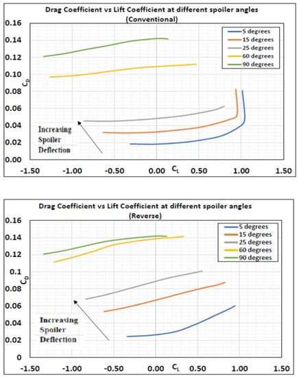
Figure 19.
Lift/drag polar for a representative spoiler configuration, showing the effect of spoiler deflection for the conventional (top) and reverse (bottom) spoiler.
Figure 20 shows directly how the difference in lift and drag coefficient changes with spoiler angle at an angle of attack of 0 degrees compared to a clean airfoil (without the spoiler), for both spoiler types. From Figure 20, it can be seen that both spoiler types perform similarly in terms of reducing the lift coefficient, with performance benefits when using the reverse hinge at lower spoiler deflections. However, the drag shows a large difference, with the reverse hinge significantly outperforming the conventional spoiler by increasing the drag by a roughly constant ΔCD, except at the extremes (90 degrees), where the two configurations become more similar. Figure 21 shows the difference in lift and drag coefficient changes with spoiler deflection at an angle of attack of 6 and 12 degrees. As the angle of attack is increased to 6 degrees, we can see a clear reduction in the lift for the reverse hinge compared to the conventional spoiler’s overall deflections, with the max -ΔCL difference being seen at deflections of 15 and 25 degrees. For example, at a 25-degree spoiler deflection, the reverse spoiler reduces the ΔCL by 24.5% and increases the ΔCD by 120% compared to a conventional spoiler. As previously, the reverse hinge shows an increase in drag across all configurations, with a roughly constant ΔCD at deflections of 15, 25, and 60 degrees.
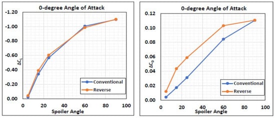
Figure 20.
Difference in lift and drag coefficients compared to a clean airfoil for both spoiler types varying with spoiler deflection (0-degree AOA).
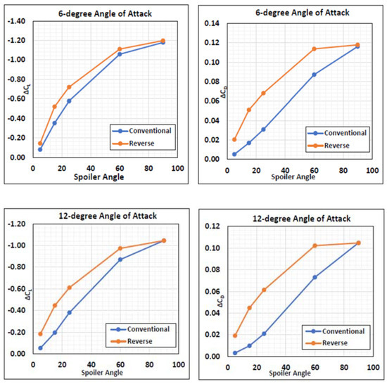
Figure 21.
Change in lift and drag coefficients compared to a clean airfoil varying with spoiler deflection at a 6-degree AOA (top) and 12-degree AOA (bottom).
Increasing the angle of attack to 12 degrees widens the performance gap between the reverse and conventional spoiler as the differences between the lines (Δ(ΔCL) and Δ(ΔCD)) increase, where it can be seen that the reverse spoiler performs much better. The reason for the general trend of decreasing Cl and increasing Cd with increased spoiler deflection is well understood in the literature [10]. As the deflection of the spoiler increases, the flow must turn by a larger angle, and the circulation around the airfoil is reduced. This slows down the flow in front of the spoiler and higher adverse pressure gradients cause a separation bubble (hinge) in front of the spoiler. The pressure on the lower surface reduces upon increasing spoiler deflection due to the reduction in circulation and change in effective camber. Figure 22 below shows the general pressure distribution on the airfoil surface upon increasing spoiler deflection for the conventional spoiler at a 0-degree angle of attack. As expected, a higher spoiler deflection corresponds to a higher pressure build-up on the upper surface and lower pressure on the lower surface. At low spoiler deflections, the change in pressure coefficient close to the airfoil changes much more gradually.
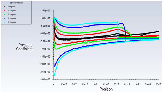
Figure 22.
Pressure distributions upon varying spoiler deflection for the conventional spoiler at a 0-degree AOA.
The corresponding plot (Figure 23) for the reverse hinge shows some clear changes when using the novel design. Unlike the conventional case, at all spoiler deflections, the reverse hinge shows a sharp drop-off in pressure coefficient (vertical drop) upon separating around the spoiler. Another noticeable difference is how much closer the reverse 60-degree spoiler angle matches the 90-degree one in terms of pressure coefficient on the suction and pressure surface, with the only difference being the earlier separation point.
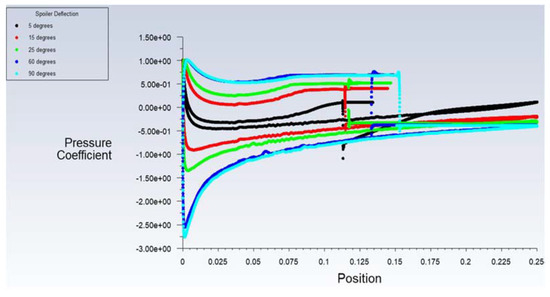
Figure 23.
Pressure Distributions upon varying spoiler deflection for the reverse spoiler at a 0-degree AOA.
Even though the general trend is that the reverse spoiler performs better at higher angles of attack, the improvement seen for moderate deflections (15 and 25 degrees) is still significant at low angles of attack, which coincides more with the operating range that spoilers are likely to be utilized. At an angle of attack of zero degrees, there is a 14.2% and 6.5% reduction in lift and a 50.9% and 42.1% increase in drag compared to a conventional spoiler when using the reverse spoiler at deflections of 15 and 25 degrees, respectively.
To investigate these improvements seen at moderate spoiler angles of 15 and 25 degrees, Figure 24 shows the pressure distributions for both spoiler types at 15 and 25 degrees at a 0-degree angle of attack. This distribution highlights the reverse spoiler’s effect of inducing a much higher pressure forward of the spoiler, which is also clear to see in the static pressure contour plots (Figure 24). The pressure on the lower surface also reduces with increasing spoiler deflection due to the reduction in circulation. This is shown on the pressure distribution plots and static pressure contour plots. The pressure distributions highlight also that higher deflection angles induce a higher pressure, and the reverse spoiler type increases the pressure further than the conventional spoiler. The pressure on the lower surface of the reverse spoiler configurations is also much lower than its conventional counterpart.
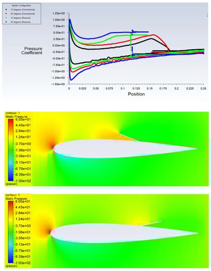
Figure 24.
Pressure distribution comparison at moderate spoiler angles (15° and 25°) for both spoiler types (conventional and reverse) (top) and the static pressure contour plots for conventional and reverse spoilers (middle & bottom ones) at a 15-degree spoiler angle and AOA = 0 degrees, respectively.
Figure 25 shows a 15-degree spoiler deflection for the reverse and conventional configurations at angles of attack of 6 and 12 degrees. As can be seen from these figures, the performance of the reverse spoiler improves comparatively as you increase the angle of attack. In both cases, the conventional hinge has a much larger suction peak on the upper surface, and the pressure stays lower on the upper surface until after the spoiler region, where you get a constant base pressure region. At the 12-degree angle of attack, it is interesting to notice the influence of the spoiler lessons, especially for the conventional, with a very slight variation in the pressure coefficient in the region around the spoiler. As the spoiler is at a high angle of attack, the flow separates earlier from the airfoil and thus the flow essentially does not interact with the spoiler as much. The reverse hinge improves this as it protrudes backward into the flow, meaning it is closer to the separation region and you can still see a clear drop in pressure after the spoiler. The difference in the drag values is significant between the reverse and conventional spoilers for all spoiler deflections and angles of attack. The reason for this is due to the higher induced pressure in front of the reverse spoiler. As the pressure behind the spoiler is fixed to a base pressure, there is a larger pressure difference upstream and downstream of the spoiler, increasing pressure drag.
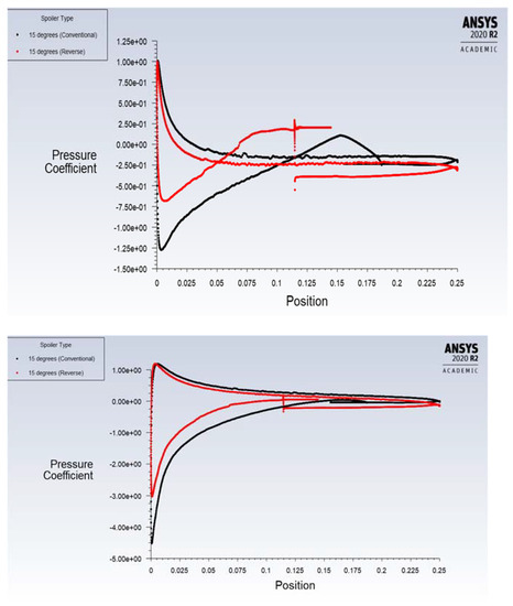
Figure 25.
Pressure distributions of both spoiler types with a 15-degree spoiler deflection at a 6-degree AOA (top) and 12-degree AOA (bottom).
4.3. Effect of Spoiler Length
The effect that spoiler length has on both spoiler types (conventional and reverse hinge) was investigated to see if there was a difference in how the reverse and conventional were affected. Note that all figures in this section show the results for a representative spoiler configuration (0.6C spoiler position, 25-degree spoiler deflection). Two different spoiler lengths were tested, which were of typical lengths used (0.1C and 0.15C). Figure 26 shows the difference in lift and drag coefficients against the angle of attack compared to a clean airfoil for the conventional and reverse spoiler at different spoiler lengths. Increasing the spoiler length increases the negative camber and causes the flow to turn by a larger angle. This spoils the flow more, leading to a reduction in lift and an increase in drag. This is an effect seen by both spoiler types and the offset in the lift is similar for both is similar. Whereas, for drag, increasing the spoiler length for the reverse hinge seems to improve the performance more as the absolute difference between the lines is far greater.
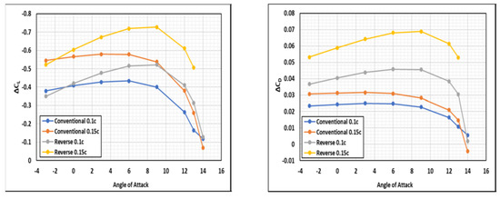
Figure 26.
Effect of spoiler length on the conventional and reverse spoilers at a 25-degree spoiler deflection angle.
The reason for this increase in drag is shown by the pressure distributions. From Figure 27, it is clear to see that a larger spoiler causes the adverse pressure gradient forward of the spoiler to be higher, and the difference between the conventional and reverse spoiler is noticeable. This combined with the larger area over which the pressure is acting means that the drag performance of a reverse spoiler improves with spoiler length compared to a conventional spoiler. Along with this, these figures show the clear performance benefits of the reverse hinge. Even the 0.1C reverse spoiler increases drag by more than a 0.15C conventional spoiler. The gradient of the lift slope is greater for the reverse hinge spoiler, which shows its improving performance as the angle of attack increases; e.g., at a 9-degree angle of attack, the reverse 0.1C spoiler matches the 0.15C conventional spoiler closely in terms of lift reduction (Figure 26)
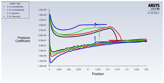
Figure 27.
Pressure distribution comparing the effect of spoiler length on the conventional and reverse spoiler.
5. Conclusions
In this paper, a novel unconventional spoiler design named a reverse hinge, which is hinged at its rear and rotates toward the trailing edge is proposed. The performance of a NACA0012 airfoil with a spoiler (conventional and reverse hinge) was investigated using two-dimensional Reynolds-Averaged Navier–Stokes (RANS) simulations with the k-omega SST turbulence model. In this study, a comparison between the conventional and reverse hinge spoiler was done over a range of spoiler positions, spoiler angles, spoiler lengths, and angles of attack, to investigate the performance over a wide range of potential configurations. From this study, it is found that for the lift, the novel reverse hinge spoiler tends to be better as you increase the angle of attack and performs best at spoiler angles of 15 and 25 degrees; in turn, for drag, the reverse hinge performs better in terms of increasing drag consistently across all the different configurations. For example, at a 25-degree spoiler deflection angle, the reverse spoiler reduces the ΔCL by 24.5% and increases the ΔCD by 120% compared to a conventional spoiler at an angle of attack of 6-deg and a spoiler length of 0.15C. For the spoiler length variation, it is found that the effect of the reverse hinge is undoubtedly enlarged when increasing the spoiler length from 0.1C to 0.15C with the length being normalized with respect to the chord of the airfoil. Moreover, it is found that the reverse spoiler with a shorter length (0.1C) can match the performance of the conventional spoiler with a higher length (0.15C). These findings may have some implications for the aircraft industry, as the reverse spoiler could be used to perform the same application as conventional spoilers used today, but either using a shorter length or deflection angle. The first option potentially reduces the weight of the actuation system required and the second option improves and extends the amount of aircraft control.
Author Contributions
All authors participated in every session. All authors have read and agreed to the published version of the manuscript.
Funding
The work presented herein has been partially funded by Abu Dhabi Education Council Award for Research Excellence Program (AARE 2019) through grant number AARE19-213.
Institutional Review Board Statement
Not applicable.
Informed Consent Statement
Not applicable.
Data Availability Statement
Not applicable.
Acknowledgments
The authors like to thank the GDP34 (20/21) Team at the University of Southampton for their significant contribution to this work. In addition, RM Ajaj likes to thank Muhammed S. Parancheerivilakkathil for regenerating some of the figures in this paper. The work presented herein has been partially funded by Abu Dhabi Education Council Award for Research Excellence Program (AARE 2019) through grant number AARE19-213.
Conflicts of Interest
The authors declare no conflict of interest.
References
- Andrisani, D.; Gentry, G.L.; Stickle, J.W. Wind Tunnel Study of Slot Spoilers for Direct Lift Control; NASA Technical Report; Langley Research Centre: Hamtpon, VA, USA, 1972. [Google Scholar]
- Harley, C. Aerodynamic Performance of Low Form Factor Spoilers. Ph.D. Thesis, University of Manchester, Manchester, UK, 2010. [Google Scholar]
- Fitzpatrick, J.E.; Furlong, G.C. Effect of Spoiler-Type Lateral-Control Devices on the Twisting Moments of a Wing of NACA 230-Series Airfoil Sections; Langley Memorial Aeronautical Laboratory: Hampton, VA, USA, 1947. [Google Scholar]
- Waszak, M.R. Robust Multivariable Flutter suppression for benchmark active control technology wind tunnel model. AIAA J. 2001, 24, 147–153. [Google Scholar] [CrossRef]
- Payne, B.W. Designing a load alleviation system for a modern civil aircraft. In Proceedings of the 15th International Council of the Aeronautical Sciences, London, UK, 7–12 September 1986; pp. 283–291. [Google Scholar]
- Weick, F.E.; John, R.T. Resume and Analysis of NACA Lateral Control Research. NACA; Langley Memorial Aeronautical Laboratory: Hampton, VA, USA, 1937. [Google Scholar]
- Wentz, J.R.; Ostowari, C.; Seetharam, H.C. Effects of design variables on spoiler control effectiveness, hinge moments and wake. In Proceedings of the 19th AIAA Aerospace Sciences Meeting, St. Louis, MO, USA, 12–15 January 1981. [Google Scholar]
- McLachlan, B.G.; Karamcheti, K.; Joint Institute for Aeronautics and Acoustics. An Experimental Study of Airfoil Spoiler Aerodynamics; Stanford University: Stanford, CA, USA, 1984. [Google Scholar]
- Mashud, M.; Ferdous, M.; Omee, S.H. Effect of spoiler position on aerodynamic characteristics of an airfoil. Int. J. Mech. Mechatron. Eng. 2012, 12, 1–6. [Google Scholar]
- Lee, C.S.; Bodapati, S. Experimental investigations of the flowfield of an airfoil with spoiler. AIAA J. 1987, 25, 1411–1416. [Google Scholar] [CrossRef]
- Kalkanis, P. Numerical Simulation of Spoiler Flows. Ph.D. Thesis, Imperial College of Science and Technology, South Kensington, UK, 1988. [Google Scholar]
- Geisbauer, S. Numerical spoiler wake investigations at the borders of the flight envelope. In Proceedings of the 29th AIAA Applied Aerodynamics Conference, Honolulu, HU, USA, 27–30 June 2011. [Google Scholar]
- Alhawwary, M.A.; Owis, F.M.; Abdelrahman, M.M. Numerical simulation of the flowfield around airfoil with spoiler using the higher-order spectral difference method. In Proceedings of the 53rd AIAA Aerospace Sciences Meeting, Kissimmee, FL, USA, 5–9 January 2015. [Google Scholar]
- Guaily, A.; Abdelrahman, M. Numerical simulation of the vortex shedding behind an airfoil-spoiler configuration. Am. J. Aerosp. Eng. 2018, 5, 16–23. [Google Scholar] [CrossRef][Green Version]
- Askar, M.K.A.; Hameed, A.Q.; Suffer, K.H.; Razlan, Z.M. Numerical simulation of a new spoiler on upper surface of Clark Y14 wing. IOP Conf. Ser. Mat. Sci. Eng. 2018, 429, 012080. [Google Scholar] [CrossRef]
- Lindsay, S.D.; Walsh, P. Experimental investigation of spoiler deployment on wing stall. Open J. Fluid Dyn. 2018, 8, 308–320. [Google Scholar] [CrossRef]
- Tian, Y.; Feng, P.; Liu, P.; Hu, T.; Qu, Q. Spoiler Upward Deflection on Transonic Buffet Control of Supercritical Airfoil and Wing. J. Aircr. 2017, 54, 1229–1233. [Google Scholar] [CrossRef]
- Geisbauer, S.; Loeser, T. Towards the investigation of unsteady spoiler aerodynamics. In Proceedings of the 35th AIAA Applied Aerodynamics Conference, Denver, CO, USA, 5–9 June 2017. [Google Scholar]
- Geisbauer, S. Numerical simulation and validation of aerodynamics of static and dynamic spoilers. J. Aircr. 2021, 58, 1187–1203. [Google Scholar] [CrossRef]
- Juretic, F.; Kozmar, H. Computational modeling of the atmospheric boundary layer using various two-equation turbulence Models. Wind. Struct. 2014, 19, 687–708. [Google Scholar] [CrossRef]
- Fillola, G.; Carrier, G.; Rodde, A.M.; Dor, J.B. Experimental study and numerical simulation of flow around wing control surface. In Proceedings of the 25th International Congress of Aeronautical Sciences, Hamburg, Germany, 3–8 September 2006. [Google Scholar]
- Pope, S.B. Turbulent Flows; Cambridge University Press: Cambridge, UK, 2000. [Google Scholar]
- Ansys Fluent. Available online: https://www.afs.enea.it/project/neptunius/docs/fluent/html/th/node67.htm (accessed on 15 May 2022).
- Roache, P.J. Code verification by the method of manufactured solutions. J. Fluid Eng. 2002, 1, 4–10. [Google Scholar] [CrossRef]
- Coleman, H.; Freitas, C.J.; Crane, R.L.; Blackwell, B.F.; Dowding, K.J.; Ghia, U.; Hills, R.G.; Logan, R.W.; Roache, P.J.; Steele, W.G., Jr. ASME V&V 20–2009; Standard for Verification and Validation in Computational Fluid Dynamics and 24 Heat Transfer; ASME: New York, NY, USA, 2009. [Google Scholar]
- Slater, J.W. Examining Spatial (Grid) Convergence, NASA. 2008. Available online: https://www.grc.nasa.gov/www/wind/valid/tutorial/spatconv.html (accessed on 15 May 2022).
- Mark, D. XFOIL Subsonic Airfoil Development System. Available online: https://web.mit.edu/drela/Public/web/xfoil (accessed on 15 May 2022).


Publisher’s Note: MDPI stays neutral with regard to jurisdictional claims in published maps and institutional affiliations. |
© 2022 by the authors. Licensee MDPI, Basel, Switzerland. This article is an open access article distributed under the terms and conditions of the Creative Commons Attribution (CC BY) license (https://creativecommons.org/licenses/by/4.0/).