Communication

Efficiency Improvement of an Electric-Grid Transformer Using the Diamagnetism Characteristics of a Bulk Superconductor

by
Daniel Shaked
1 and
Eldad Holdengreber
2,3,*
1
Department of Electrical and Electronic Engineering, Ariel University, Ariel 40700, Israel
2
Department of Mechanical Engineering and Mechatronics, Ariel University, Ariel 40700, Israel
3
Department of Electrical and Computer Engineering, University of Waterloo, Waterloo, ON N2L 3G1, Canada
*
Author to whom correspondence should be addressed.
Energies 2022, 15(19), 7146; https://doi.org/10.3390/en15197146
Submission received: 18 August 2022 / Revised: 22 September 2022 / Accepted: 26 September 2022 / Published: 28 September 2022

Abstract

:
An innovative method to improve the efficiency of a single-phase electric-grid 125 kVA, 50 Hz shell type and distribution transformer is presented. The diamagnetism characteristic of a bulk high-temperature superconductor (HTS), designed in a specific dimension, is used to construct a magnetic shield around the air gaps that form between the core joints and among the coils of the transformer. Consequently, the shielded flux engages the core area and increases the flux density in the core, resulting in an increase in the output power, and hence an improved transformer efficiency. The transformer was designed and simulated using advanced electromagnetic software. Simulation results indicate that the width and thickness of the HTS material, as its precise location placed on the air gaps around the core and the coils, can be a substantial factor in generating a magnetic shield that results in an efficiency improvement, superior compared to conventional transformers. The most enhanced performance was received for HTS thickness of 2.6 mm, around 2.4% output power improvement compared with a conventional transformer model. In a transformer of this type that efficiency improvement can lead to great energy savings, around 10,000 kWh for half a year of working under load.

1. Introduction

Due to the increasing demand for electric power, an improvement in the efficiency of power transformers is becoming more necessary. Any improvement in the efficiency of these transformers, even the most minor, can lead to a significant energy saving and operation cost reduction. For this reason, great efforts are being made in order to minimize all kinds of losses [1,2].
Leakage flux is one of the transformer losses that causes voltage drops in both primary and secondary winding and hence directly affects the transformer efficiency. This loss is defined as all the flux that is scattered in the air gaps around the transformer’s conducting coils and not participating in the energy transfer process. Although leakage flux can be effective as a short circuit limiter, it is mostly considered as the loss that effects the transformer operation under the secondary voltage load drop [3]. In addition to that, leakage flux is defined as a part of the losses known as stray loss.
Stray losses, mainly caused by leakage flux from winding, are not a direct power loss, but ones that are created from the interaction with the construction and surrounding elements of the transformer. This interaction causes eddy currents that raises the temperature of the transformer, and in extreme cases of rapid load changes, can damage the insulation of the transformer elements [4]. The higher the power of the transformer is, the intensity of the leakage flux will be higher and will grow rapidly [5]. Inefficient design of the transformer structure for leakage flux reduction, can roughly affect transformer performances [6,7]. There are several methods to reduce leakage flux in transformers. Among them is the reduction of the coil size and the minimization of the air gaps between them [8]. Locating the transformer coils as adjacently as possible improves the coupling and reduces the leakage flux that can fringe out the air gaps [9]. Other methods use magnetic shunts that prevent from the leakage flux reaching undesirable areas [10].
One of the promising developments for loss reduction in electrical devices is superconductor technology. Among them are the superconducting transformers [11]. High-temperature superconductors (HTS) have a highly applied orientation, thanks to their ability to work at 77 K [12,13,14,15,16]. Superconductor bulk materials proved to be efficient in creating magnetic shields for high-frequency transformers [17].
The magnetic shielding properties of the bulk tube HTS were studied at low AC frequency in an axial magnetic field to show the dependence of the thickness and dimensions of bulk tube HTS on magnetic field shielding. The HTS bulk tube was found to be effective in shielding an axial induction [18].
In this paper we investigate the possibility of improving the efficiency of a distribution single-phase shell type transformer by shielding the leakage flux, using bulk HTS material. By performing advanced electromagnetic simulations, optimizing the superconducting material dimensions over the transformer air gaps, we obtained an optimal design of a bulk superconducting shielded transformer (BSST). The design of both single-phase shell-type transformers, conventional and BSST, is presented in Section 2. Section 3 summarizes the design simulation results of the two models and presents the comparison between them.

2. Transformers Design

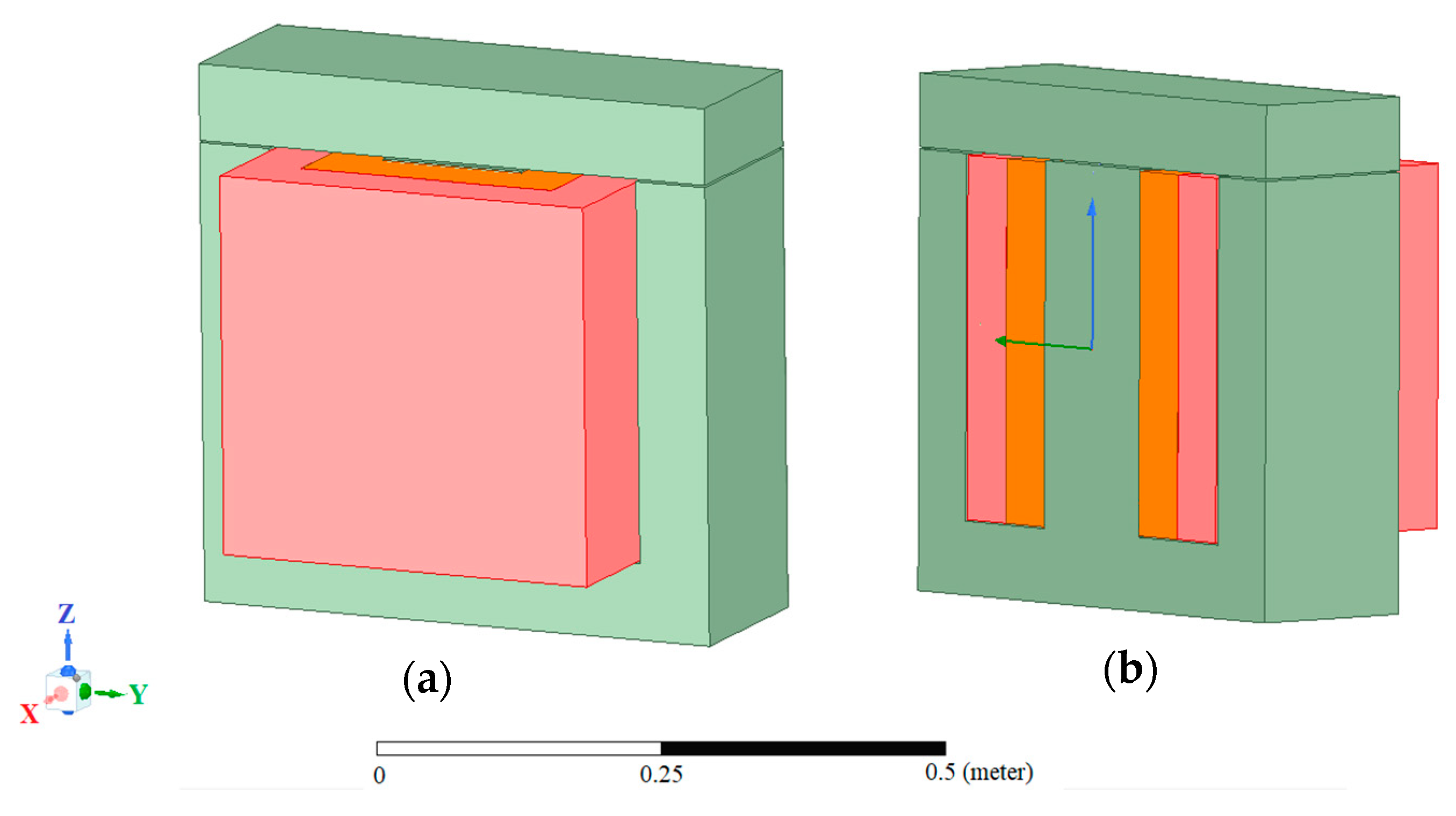
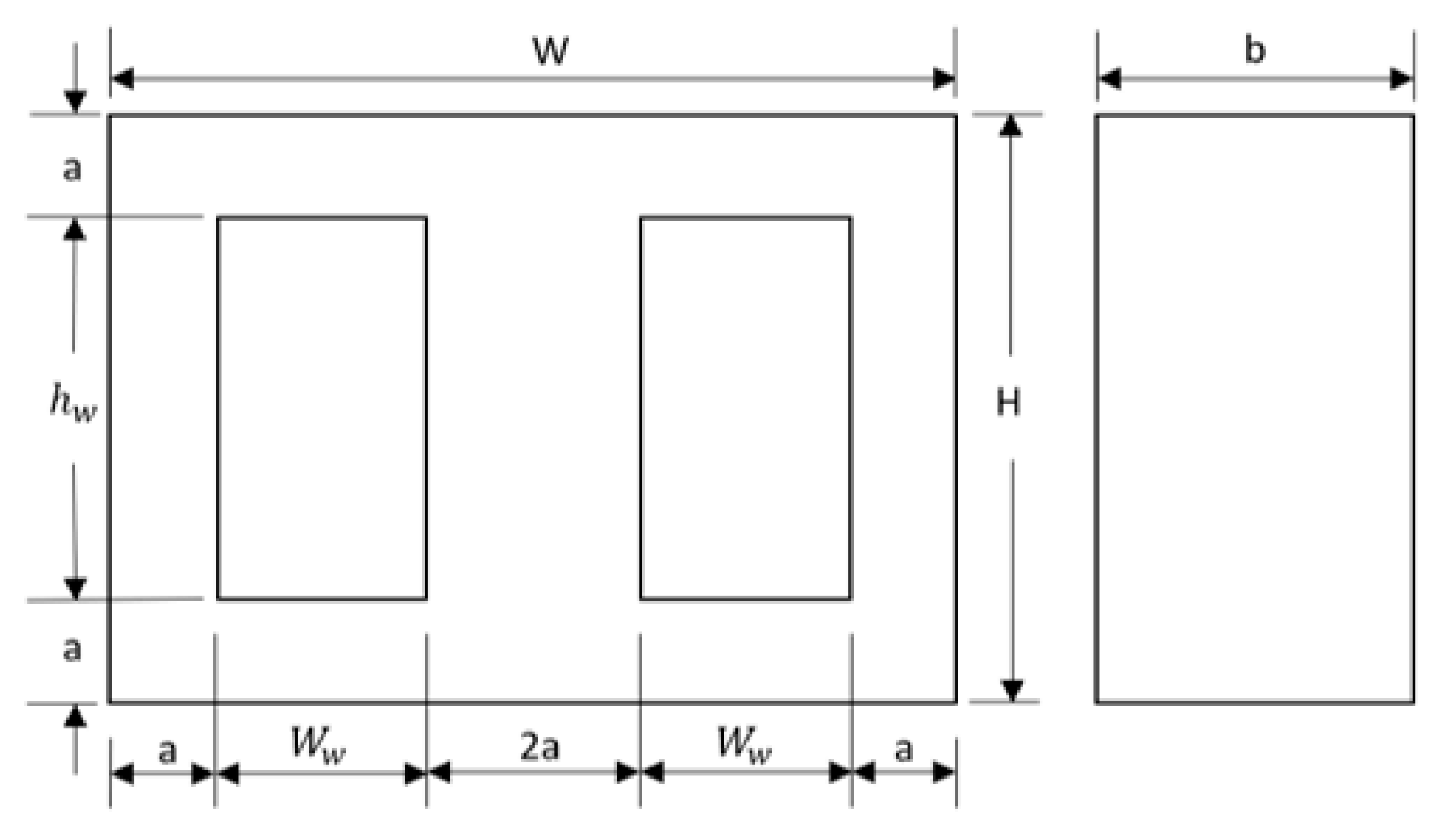
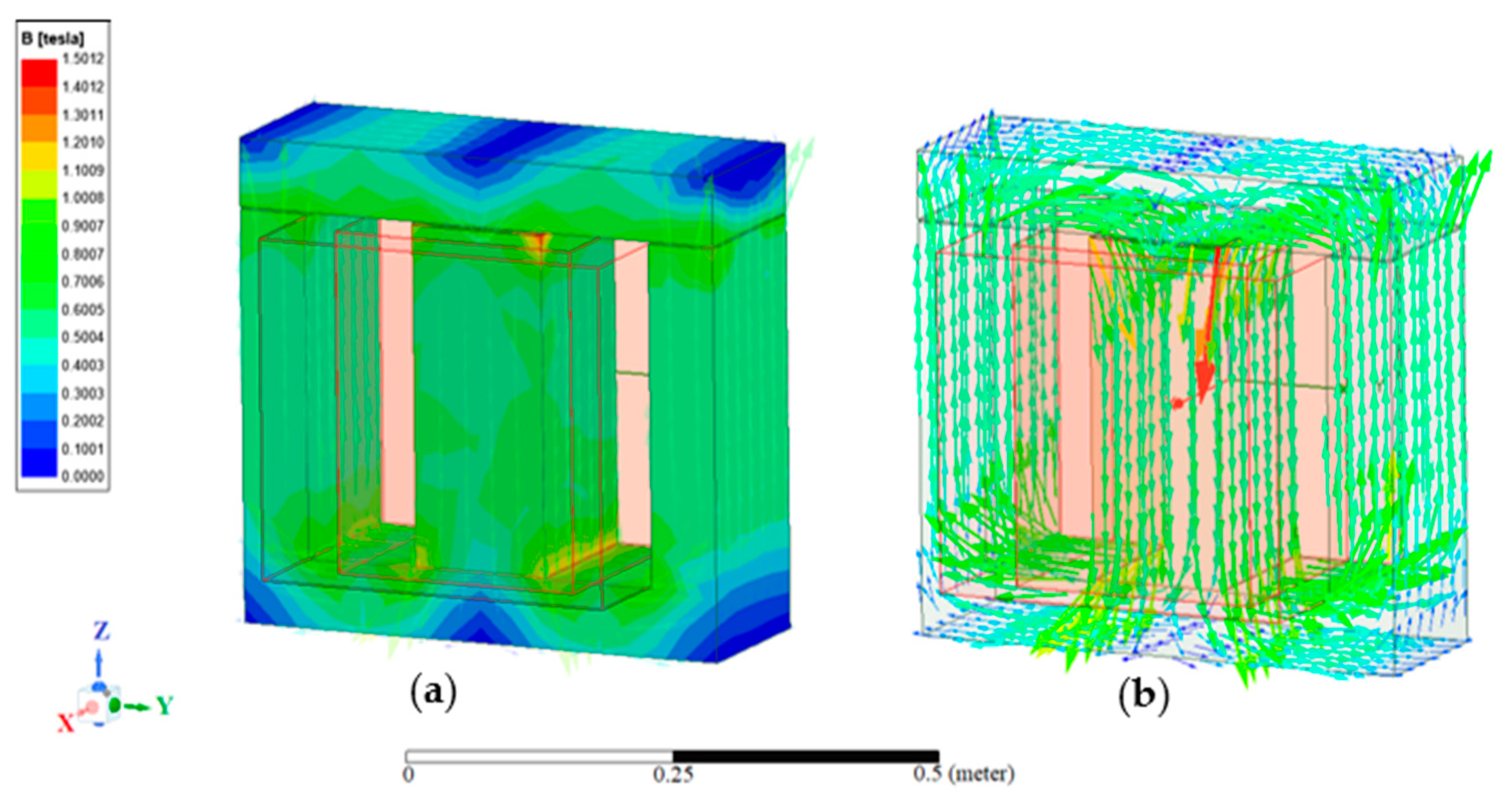
2.1. The Conventional Transformer Model Design

In order to examine the magnetic flux shielding effect generated by the HTS material on the efficiency of a transformer, a conventional model of a distribution single-phase step-down, shell-type transformer was designed. A distribution transformer is a transformer that by most industry standards is power rated up to 500 kVA for single-phase and up to 5000 kVA for three-phase transformer. This transformer takes voltage from a primary distribution circuit and “steps down” the voltage to a secondary distribution circuit or consumers service [19]. The model was simulated through Ansys Maxwell software in transient mode in order to measure the induced voltages and currents in the transformer’s windings and to examine the flux density in the core. The model consists of a shell type E-I shape magnetic core and two high and low voltage copper windings that wind around the central limb, surrounded by air in room temperature. The schema of the transformer core dimension is presented in Figure 1.
W’ is the core width, ‘H’ is the core height, ‘hw’ is the window height, ‘Ww’ is the window width, ‘a’ is the width of the outer limb and b is the core depth. The core parameters were optimized for the following power-grid transformer specifications: 125 kVA power rate, step down voltage ratio of 6.6/0.4 kV, volts per turn of 10 V, and frequency of 50 Hz. Other specifications determined for the core and winding calculation are: 2 amp/mm2 current density, a 1.1 T flux density in the core, a 0.33 window space factor, and a stacking factor of 0.9. The ratio between the core depth and central limb width is b/2a = 2.5. The design optimization results yield the following core dimensions: W = 0.495 m, H = 0.46 m, b = 0.3375 m, and a = 0.0675 m. Table 1 summarize the transformer main technical data.
Table 2 summarizes the transformer’s material parameters involved in the simulation.   μ r is the relative permeability, which varies non-linearly in a magnetic flux density range values (B) of 1.5 to 2.5 T for magnetic field strength values (H) of 0 to 3 × 10⁵ A/m. P L is the power density of the core loss model; it varies non-linearly in the range of 0 to 0.5 W/m3, for the magnetic flux density range of 0 to 1 T. K h   is the hysteresis loss coefficient, K c is the eddy current loss coefficient, K e is the magnetic and electric operating condition coefficient, and ρ   is the mass density.
Figure 2a,b, respectively, show the half symmetric views of the simulated model. The two E-I core parts (the two green parts in Figure 2) were separated with a 1 mm air gap. The primary copper winding, i.e., the orange part in Figure 2, was separated from the secondary winding, i.e., the pink part in Figure 2, through a 1 mm air gap. In addition, the secondary copper winding was separated from the transformer core with a 1 mm air gap.
The emphasis of this work is on the improvement of the transformer efficiency. The efficiency of a transformer is described using the following equation [20]:
η = P o u t P o u t + P f e + P c u
where η is the transformer efficiency, P o u t is the output power, i.e., the multiplication of the output voltage and current, measured in the secondary winding, and P f e and P c u are the losses of the transformer core and winding, respectively. Equation (1) demonstrates that, in order to improve the efficiency of a transformer, one should improve the transformer output power, considering changes in the sum of losses.
For AC excitation, it is known that the maximum induced voltage in the N-turns windings is proportional to the maximum flux density in the core, as described in the following Equation (2) [20]:
E m a x = 2 π f N A c B m a x
where E m a x is the maximum induced voltage in the winding, f is the frequency of the voltage source, N is the number of turns of winding, A c is the central limb cross section area and B m a x is the maximum flux density in the core. According to Equation (2), in order to improve or maximize the induced voltage, one should maximize the flux density in the transformer core.
Figure 3a,b, respectively, show the flux density surface and vector representations of the conventional transformer’s core model in Ansys Maxwell simulator. Simulation results indicate a relatively uniform flux density pattern distributed through the core. The highest flux density magnitude in the central limb is in the range of ~1–1.1 T (the bar yellow range), which corresponds with the transformer original design.
Figure 4 shows the spatial scattering magnitude of the leakage flux density that leaks out from the air gaps around the core of the conventional model. This flux density leaks out from the air gaps, is in the magnitude range of ~0.1–0.2 T (the bar blue range).
For this study, a shell type transformer was chosen because its structure is very suitable for the placement of material layers in the transformer’s air gaps around the core and coil, intended to produce the magnetic shielding effect, as detailed in the next section. In addition, this shell type configuration is with high potential to reduce the amount of leakage flux in comparison to other types of transformer construction, and accordingly, a higher efficiency. For any other power transformers, or any other three-phase transformer, new research is required to adjust the thickness, location and the geometry of the PEC layers to the specific location of the transformer air gaps.

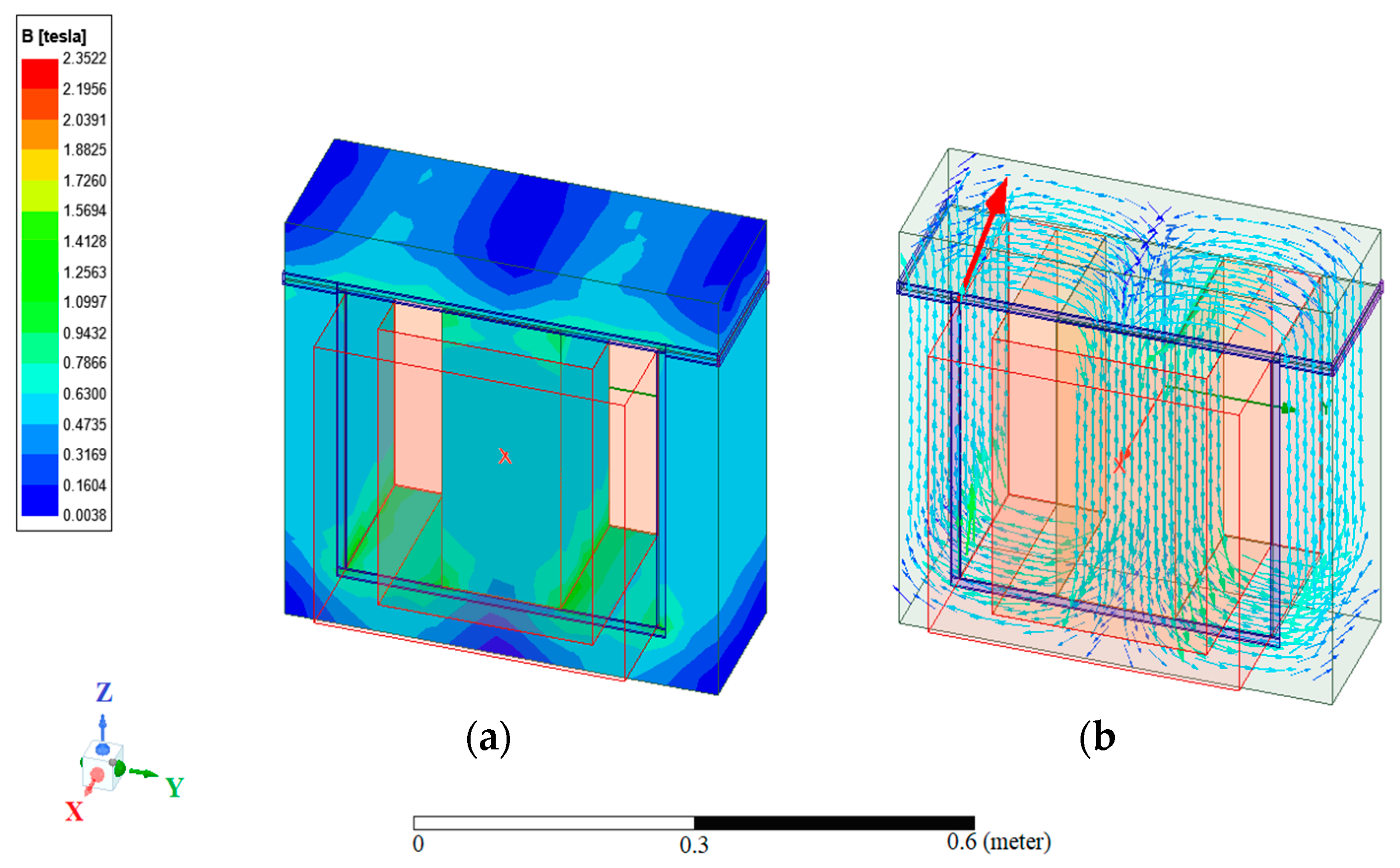
2.2. The HTS Bulk Transformer Model Design
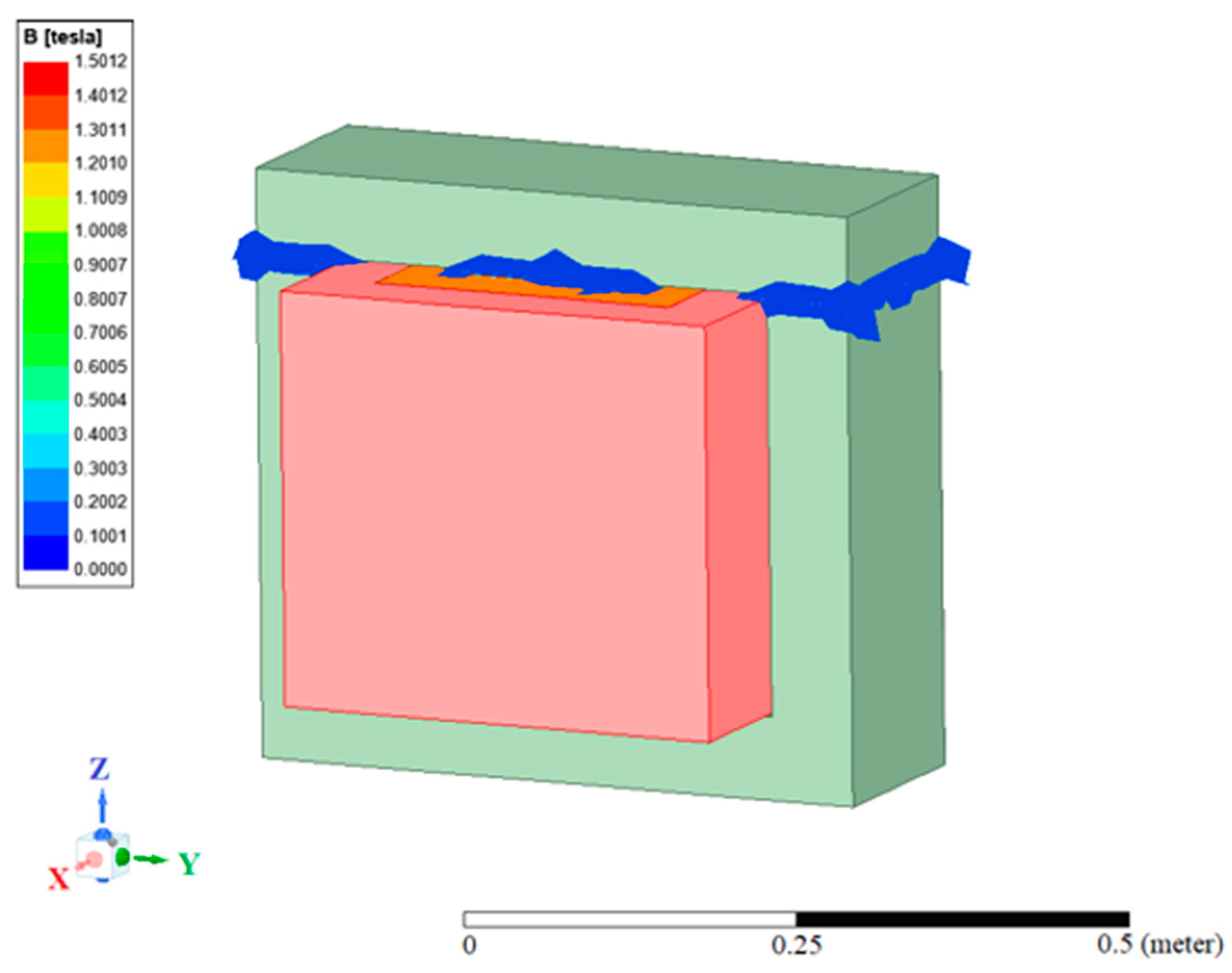
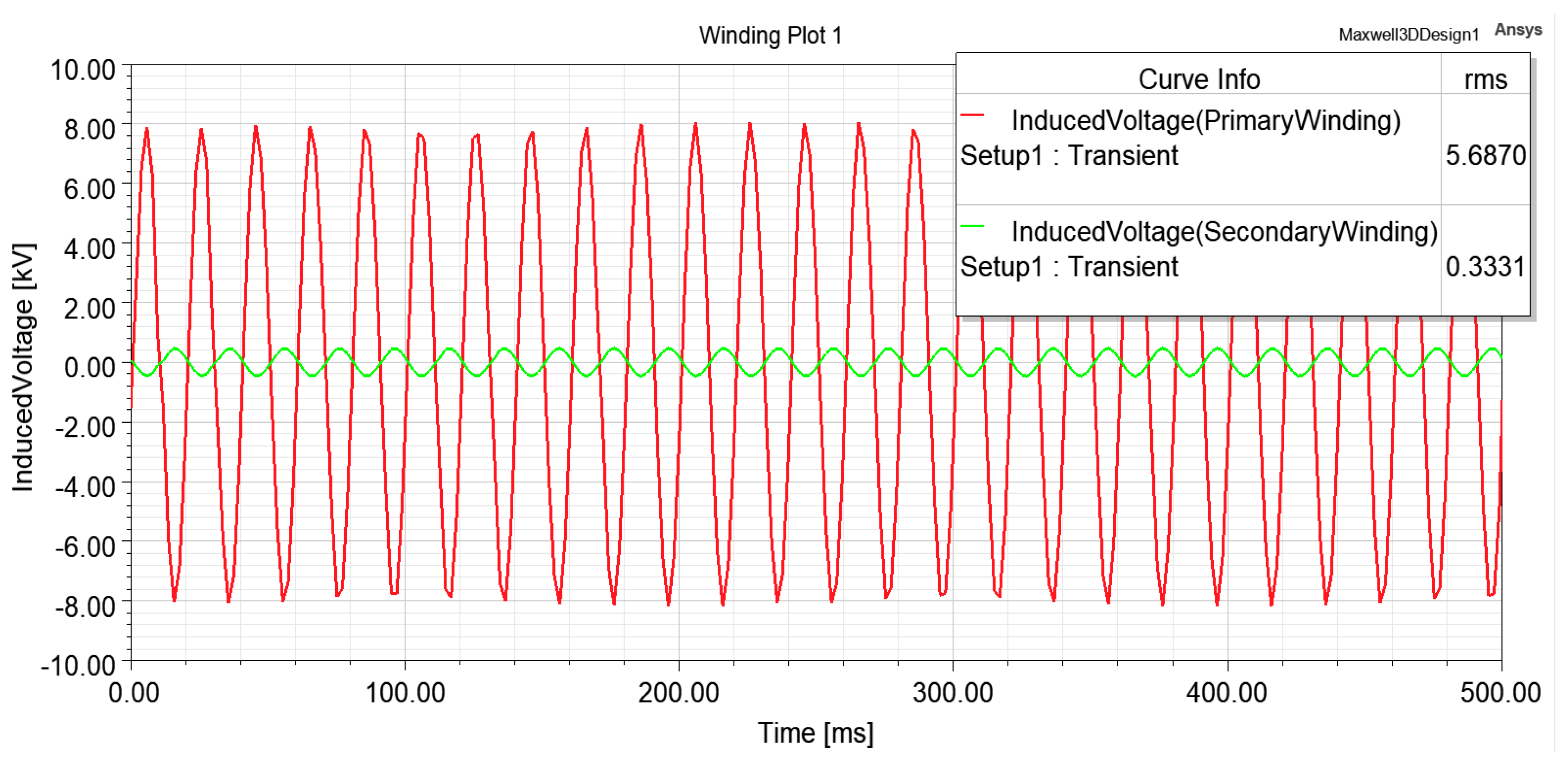
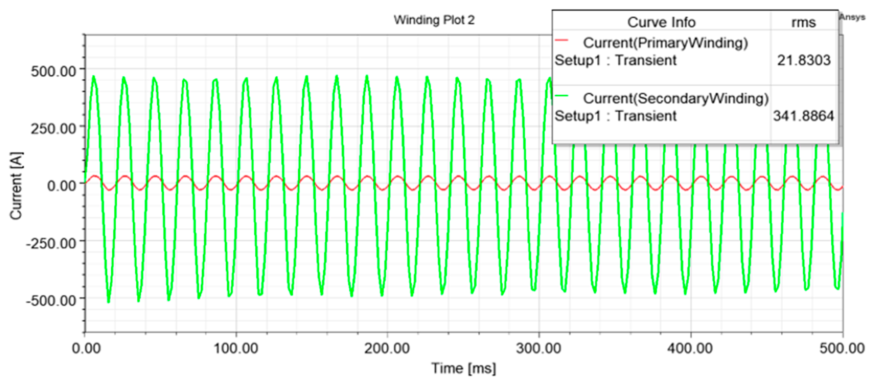
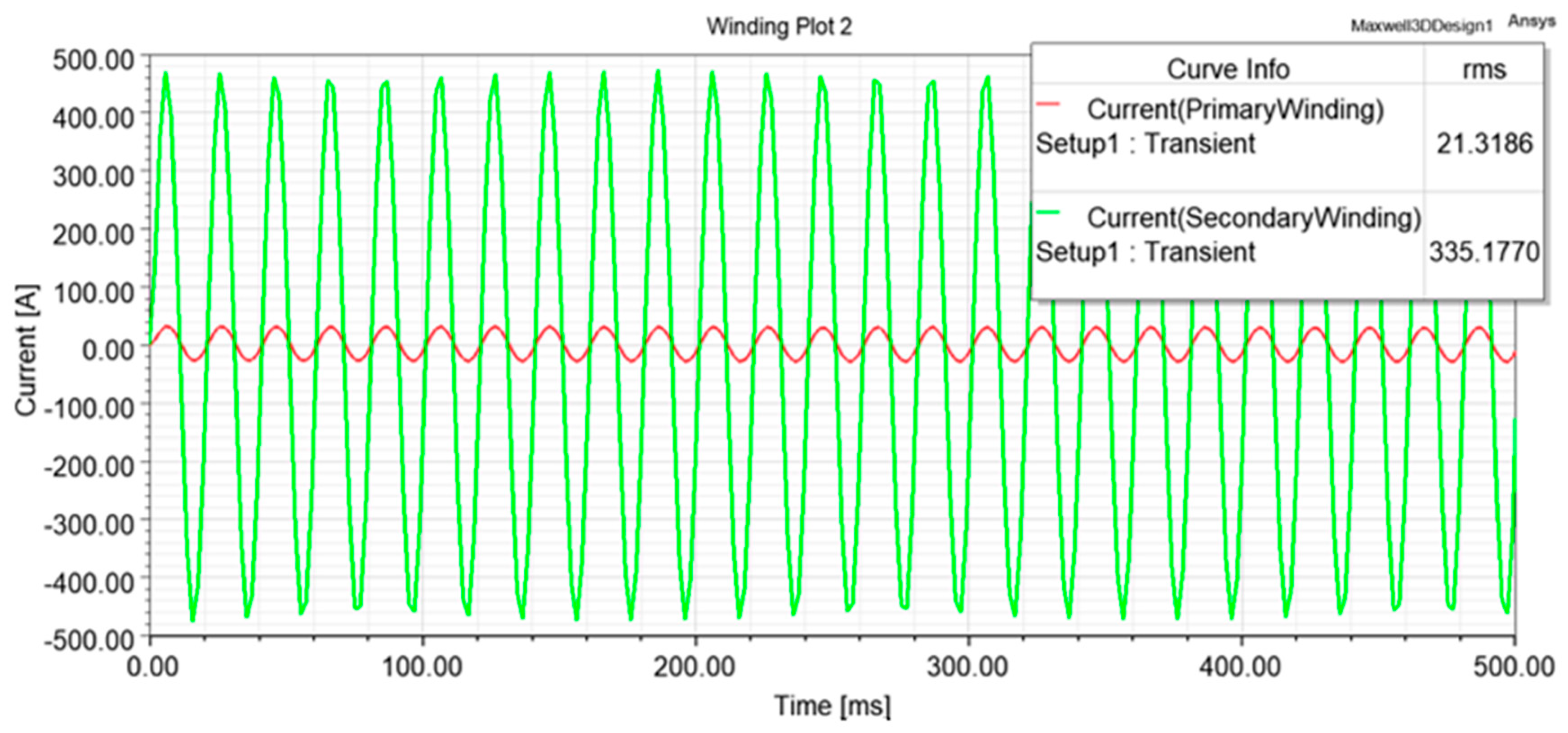
Following the spatial leaking of leakage flux observed in the conventional model simulations, we designed an improved new model, based on bulk superconductor material that shields the leakage flux that leaks through the air gaps.
In a superconducting state, the material has two unique properties, zero DC resistivity, 0 Ω, and perfect diamagnetism, χ = 1 . Perfect diamagnetism is the material’s ability to reject magnetic and electrical fields, known as the Meissner effect. Depending on magnetic field (Bc), current (Ic), or critical temperature (Tc), this effect maybe reversible [20].
Superconducting materials with Tc below 30 K are usually characterized as type I superconductors, while superconducting materials with Tc above that value are characterized as type II superconductors. Type I and type II superconductors share similar properties and characteristics, the difference between the two types is their reaction to external magnetic fields. Type I superconductors have a low critical magnetic field (typically in the range of 0.0000049 T to 1 T). Type II superconductors come with a high critical magnetic field (typically greater than 1 T) [21]. The material referred for this study is the YBa2Cu3O7 HTS bulk, a type II superconductor material, also known as YBCO or Y-123, with a threshold temperature around 92 K. YBCO is a ceramic layer of Yttrium and Barium combined with copper-oxide. It is possible to obtain critical magnetic fields of 4 T, on the surface of an YBCO bulk at 77 K (liquid nitrogen boiling point), and up to 17 T at 29 K [22,23].
The HTS YBCO bulk material was chosen for several reasons: its ability to be in a superconducting state at relatively high temperature (attractive for industrial devices), the YBCO bulk is relatively thick and its thickness can be changed as needed, and its ability to handle large magnetic fields, a necessary matter for the transformer type designed in this study.
Figure 5 shows the transformer model with the cladding of a bulk superconductor material over the air gaps between the two core parts and on the sides between the core and the secondary copper winding. In order to simulate the superconducting effects of the YBCO bulk material used for the magnetic shielding, we used a perfect electric conductor (PEC) material [24,25,26,27,28,29,30].
Figure 6a,b, respectively, show the flux density surface and vector representations in the core of the BSST model. In this model, the maximum flux density magnitude is concentrated in the central limb in the range of ~0.94–1.57 T (Green Range), higher flux density magnitude values than that observed in the conventional transformer (Figure 3).

3. Results

Figure 7 and Figure 8, respectively, show the root mean square (RMS) values of the induced voltage and current in the primary and secondary copper windings of the conventional model (without the pec). Simulation is performed for each model over 0.5 s, with time steps of 0.002 s. The RMS value of the primary copper winding induced voltage (red line) is 5.6870 kV and the RMS value of the secondary copper winding induced voltage (green line) is 0.3331 kV (Figure 7).
The RMS value of the primary copper winding current (red line) is 21.3186 A and the RMS value of the secondary copper winding induced current (green line) is 335.177 A (Figure 8).
Figure 9 and Figure 10, respectively, show the RMS values of the induced voltage and current, in the primary and secondary copper windings, in the most efficient, 2.6 mm thick PEC, BSST model. The RMS value of the primary copper winding induced voltage (red line) in this model is 5.7202 kV and the RMS value of the secondary copper winding induced voltage (green line) is 0.3344 kV (Figure 9).
The RMS value of the primary copper winding current (red line) is 21.8303 A and the RMS value of the secondary copper winding current (green line) is 341.8864 A (Figure 10).
From the values of the induced voltage (Figure 9) and current (Figure 10), one can calculate the BSST model output power, resulting in ~2.4% output power improvement compared to that of the conventional model. Improving 125 kVA transformer output power by around 2.4% improves the power consumption by 2.68 kW, up to 10,000 kWh for half a year of working under load.
Table 3 shows the results obtained following an optimization process. During this process different values of PEC dimensions (thickness and width) were simulated. The table mainly focused on the performance of the transformer for different thickness of PEC.
The PEC transformer model with the highest secondary winding output power obtained for a PEC thickness of 2.6 mm, and a width of 13.2 mm.
The output power for this thickness improved in 2.4%, compared to the non-PEC conventional model. On the contrary, for other PEC thickness values, such as 1 mm and 3 mm, the output power obtained is worse than that of a conventional transformer. These results emphasize the importance of optimizing the dimensions of the bulk HTS shielding material for a specific transformer.
Based on the ANSYS numerical analysis results, one can conclude that the output power can improve or deteriorate, depending on the thickness of the PEC layer, which creates the magnetic shielding effect. For PEC thickness values smaller than 1 mm, no effective magnetic shielding was observed. For this reason the optimization process was performed for PEC layers greater than that thickness value. For example, for 1 mm thickness, the output power was deteriorated in 0.43% in relation to the conventional, non-PEC, model. For PEC thickness values greater than 1 mm, an improved output power trend is obtained. The maximum values on the secondary coil of the induced current, 341.88 A, and the induced voltage, 334.4 V, obtained for a PEC thickness value of 2.6 mm. For PEC thickness values greater than 2.6 mm, as for example a thickness value of 2.8 mm, the transformer output power was deteriorated in 3.6% in relation to the conventional model (Table 3).
Table 4 shows a typical data of several 125 kVA rated power commercial transformers and the conventional and optimized BSST models. The table refers to the different transformer’s configuration characteristics, such as: dimensions, operating frequency, Environmental temperature and the iron losses with no load. The data in the table indicate that the dimensions of the BSST model are relatively smaller than those of the commercial transformers, in addition, this type of transformer will have to work under cryogenic cooling conditions [31]. Another notable issue is that the change in the iron losses between the conventional and the BSST is negligible compared to the improvement in the output power. In conclusion, the BSST model is the only transformer configuration, in relation to those shown in the table, that can offer a solution to the leakage flux problem, which can lead to great energy savings over time.

4. Conclusions

An innovative method for efficient improvement of an electric-grid transformer using the diamagnetism characteristic of a bulk HTS material was introduced. The HTS transformer model was developed by placing bulk HTS material over the air gaps of a conventional transformer model. Optimization process was carried out using advanced electromagnetic simulations for different bulk HTS material dimensions, thickness and width. An output power improvement of around 2.4%, compared to that of the conventional transformer model, obtained for width of 13.2 mm and thickness of 2.6 mm. For part of the other PEC dimensions, tested in simulation, the PEC transformer output power has deteriorated relative to the conventional transformer model, which emphasizes the importance of the optimization process. Future implementations of this technology in larger electric grid transformers than the one tested in this study can even result in greater energy saving.

Author Contributions

Conceptualization, D.S. and E.H.; methodology, D.S. and E.H.; software, D.S.; validation, E.H.; formal analysis, D.S.; investigation, D.S. and E.H.; resources, E.H.; data curation, E.H.; writing—original draft preparation, D.S.; writing—review and editing, E.H.; visualization, D.S.; supervision, E.H.; project administration, E.H.; funding acquisition, E.H. All authors have read and agreed to the published version of the manuscript.

Funding

This research received no external funding.

Institutional Review Board Statement

Not applicable.

Informed Consent Statement

Not applicable.

Data Availability Statement

The data presented in this study are available on request from the corresponding author.

Conflicts of Interest

The authors declare no conflict of interest.

References

  1. Karsai, K.; Kerenyi, D.; Kiss, L. Alternative Approaches for Distinguishing between Faults and Inrush Current in Power Transformers. Energy Power Eng. 2014, 6, 47620. [Google Scholar]
  2. Ashkezari, A.D.; Ma, H.; Saha, T.K.; Cui, Y. Investigation of feature selection techniques for improving efficiency of power transformer condition assessment. IEEE Trans. Dielectr. Electr. Insul. 2014, 21, 836–844. [Google Scholar] [CrossRef]
  3. Winders, J.J., Jr. Power Transformer Principles and Applications, 1st ed.; CRC Press: Boca Raton, FL, USA, 2002; Chapter 3; pp. 69–70. [Google Scholar]
  4. Karsai, K.; Kerenyi, D.; Kiss, L. Large Power Transformers; United States Department of Energy: Washington, DC, USA, 1987.
  5. Kulkarni, S.V.; Khaparde, S.A. Transformer Engineering, Design Technology and Diagnostics, 2nd ed.; CRC Press: Boca Raton, FL, USA, 2012; Chapter 5; pp. 179–181. [Google Scholar]
  6. Baker, A.; Stefan, M.; Bertillon, H.; Bertillon, K. Contribution of Leakage Flux to the total Losses. Transformers with Magnetic Shunt. Int. J. Electr. 2020, 108, 558–573. [Google Scholar] [CrossRef]
  7. Al-Abadi, A.; Gamil, A.; Schatzl, F. Optimum Shielding Design for Losses and Noise Reduction in Power Transformers. In Proceedings of the 2019 6th International Advanced Research Workshop on Transformers (ARWtr), Cordoba, Spain, 7–9 October 2019; pp. 25–30. [Google Scholar]
  8. Li, F.M.; Jin, J.X.; Sun, R.M.; Zhu, Y.P.; Tang, C.L.; Chen, X.Y. Effects of inner air gaps on the leakage field optimization of HTS transformer windings. In Proceedings of the 2015 IEEE International Conference on Applied Superconductivity and Electromagnetic Devices (ASEMD), Shanghai, China, 20–23 November 2015; pp. 19–20. [Google Scholar]
  9. Kladas, A.G.; Papadopoulos, M.P.; Tegopoulos, J.A. Leakage flux and force calculation on power transformer windings under short-circuit: 2D and 3D models based on the theory of images and the finite element method compared to measurements. IEEE Trans. Magn. 1994, 30, 3487–3490. [Google Scholar] [CrossRef]
  10. Moghaddami, M.; Sarwat, A.I.; De Leon, F. Reduction of stray loss in power transformers using horizontal magnetic wall shunts. IEEE Trans. Magn. 2016, 53, 8100607. [Google Scholar] [CrossRef]
  11. Chen, X.; Jin, J. Development and technology of HTS transformers. Res. Commun. 2007, 1, 2.1–2.7. [Google Scholar]
  12. Holdengreber, E.; Moshe, A.G.; Mizrahi, M.; Khavkin, V.; Schacham, S.E.; Farber, E. High Sensitivity High Tc Superconducting Josephson Junction Antenna for 200GHz Detection. J. Electromagn. Waves Appl. 2019, 33, 193–203. [Google Scholar] [CrossRef]
  13. Holdengreber, E.; Gao, X.; Mizrahi, M.; Schacham, S.E.; Farber, E. Superior Impedance Matching of THz Antennas with HTSC Josephson Junctions. Supercond. Sci. Technol. 2019, 32, 074006. [Google Scholar] [CrossRef]
  14. Holdengreber, E.; Moshe, A.G.; Schacham, S.E.; Mizrahi, M.; Dhasarathan, V.; Farber, E. THz Radiation Measurement with HTSC Josephson Junction Detector Matched to Planar Antenna. Appl. Sci. 2020, 10, 6482. [Google Scholar] [CrossRef]
  15. Dahan, Y.; Holdengreber, E.; Mizrahi, M.; Schacham, S.E.; Farber, E. Multi-Channel Transmitting System Based on High Temperature Superconducting Phase Shifter. IEEE Trans. Appl. Supercond. 2020, 30, 3500506. [Google Scholar] [CrossRef]
  16. Holdengreber, E.; Mizrahi, M.; Glassner, E.; Dahan, Y.; Castro, H.; Farber, E. Design and implementation of an RF coupler based on YBCO superconducting films. IEEE Trans. Appl. Supercond. 2015, 25, 1500905. [Google Scholar] [CrossRef]
  17. Fukuoka, K.; Hashimoto, M. Proposal of transformer using magnetic shielding with bulk high T/sub c/superconductors. IEEE Trans. Appl. Supercond. 2004, 14, 1126–1129. [Google Scholar] [CrossRef]
  18. Denis, S.; Dusoulier, L.; Dirickx, M.; Vanderbemden, P.H.; Cloots, R.; Ausloos, M.; Vanderheyden, B. Magnetic shielding properties of high-temperature superconducting tubes subjected to axial fields. Supercond. Sci. Technol. 2007, 20, 192–201. [Google Scholar] [CrossRef]
  19. Harlow, J.H. Electric Power Transformer Engineering, 2nd ed.; CRC Press: Boca Raton, FL, USA; Taylor & Francis Group: Abingdon, UK, 2007; Chapter 3. [Google Scholar]
  20. Chapman, S.J. Electric Machinery Fundamentals, 5th ed.; BAE Systems Australia: Adelaide, Australia, 2012; Chapter 2; p. 25. [Google Scholar]
  21. Tinkham, M. Introduction to Superconductivity, 2nd ed.; Harvard University: Cambridge, MA, USA, 1996. [Google Scholar]
  22. Tomita, M.; Murakami, M. High Temperature Superconductor Bulk Magnet that can trap magnetic fields of over 17 T at 29 K. Nature 2003, 421, 517–520. [Google Scholar] [CrossRef] [PubMed]
  23. Douine, B.; Berger, K.; Ivanov, N. Characterization of high-temperature superconductor bulks for electrical machine application. Materials 2021, 14, 1636. [Google Scholar] [CrossRef] [PubMed]
  24. Holdengreber, E.; Mizrahi, M.; Farber, E. Quasi-dynamical multi-channel coupler based on high temperature superconducting films. In Proceedings of the 2012 IEEE 27th Convention of Electrical and Electronics Engineers in Israel, Eliat, Israel, 14–17 October 2012; pp. 1–4. [Google Scholar]
  25. Holdengreber, E.; Moshe, A.G.; Dhasarathan, V.; Schacham, S.E.; Farber, E. Temperature Effect on Selectivity of HTSC Josephson Junction Detector. IEEE Trans. Appl. Supercond. 2021, 31, 1102004. [Google Scholar] [CrossRef]
  26. Holdengreber, E.; Schacham, S.E.; Farber, E. Impedance mismatch elimination for improved THz detection by superconducting Josephson junctions. In Proceedings of the Antennas and Propagation Conference 2019 (APC-2019), Birmingham, UK, 11–12 November 2019; pp. 1–3. [Google Scholar]
  27. Holdengreber, E.; Mizrahi, M.; Citron, N.; Schacham, S.E.; Farber, E. Very Low-Noise Figure HTSC RF Front-End. Electronics 2022, 11, 1270. [Google Scholar] [CrossRef]
  28. Holdengreber, E. A Serial Josephson Junction Antenna Array. In Proceedings of the 2020 IEEE International Conference on Applied Superconductivity and Electromagnetic Devices (ASEMD), Tianjin, China, 16–18 October 2020; pp. 1–2. [Google Scholar]
  29. Holdengreber, E.; Mizrahi, M.; Schacham, S.E.; Farber, E. Remote location of superconducting Josephson junction in planar antennas for improved THz detection. In Proceedings of the 2019 IEEE International Superconductive Electronics Conference (ISEC), Riverside, CA, USA, 28 July–1 August 2019; pp. 1–5. [Google Scholar]
  30. Dahan, Y.; Holdengreber, E.; Glassner, E.; Sorkin, O.; Schacham, S.E.; Farber, E. Measurement of Electrical Properties of Superconducting YBCO Thin Films in the VHF Range. Materials 2021, 14, 3360. [Google Scholar] [CrossRef] [PubMed]
  31. Citron, N.; Holdengreber, E.; Sorkin, O.; Schacham, S.E.; Farber, E. High-Performance RF Balanced Microstrip Mixer Configuration for Cryogenic and Room Temperatures. Electronics 2022, 11, 102. [Google Scholar] [CrossRef]
Figure 1. A scheme describing the dimensions of the single-phase shell-type transformer core.
Energies 15 07146 g001
Figure 2. The conventional transformer model half symmetric front view (a) and it across section view (b).
Energies 15 07146 g002
Figure 3. The flux density on the surface of the conventional transformer’s core (a) and its flux density vector representation (b).
Energies 15 07146 g003
Figure 4. The spatial scattering magnitude of flux density leaking out from the air gaps around the transformer core.
Energies 15 07146 g004
Figure 5. Transformer model with cladding of HTS bulk material over air gaps (the BSST model).
Energies 15 07146 g005
Figure 6. Flux density in the surface of the core of the BSST model (a) and its flux density vector representation (b).
Energies 15 07146 g006
Figure 7. The RMS values of the induced voltages of the conventional transformer primary (red line) and secondary (green line) copper windings.
Energies 15 07146 g007
Figure 8. The RMS values of the currents of the conventional transformer primary (red line) and secondary (green line) copper windings.
Energies 15 07146 g008
Figure 9. The RMS values of the optimized 2.6 mm thick BSST primary (red line) and secondary (green line) copper windings, induced voltage.
Energies 15 07146 g009
Figure 10. The RMS values of the BSST primary (red line) and secondary (green line) copper windings currents.
Energies 15 07146 g010
Table 1. The transformer main technical data.
ParameterValue
Type1 phase Shell
kVA125
Frequency50 Hz
HV Volts6600
LV Volts400
Table 2. Material parameters of the transformer model.
ParameterValue
μ r variable
K h 28.91
K c 0.599
K e 2.887
ρ 7872 kg/m3
P L variable
Table 3. Simulation results for different PEC dimensions and conventional transformer models.
Model TypePEC Thickness [mm]PEC Width [mm]Primary Induced Voltage [V]Primary Induced Current [A]Secondary Induced Voltage [V]Secondary Induced Current [A]Primary Induced Power [VA]Secondary Induced Power [VA]
Conventional--568721.3186333.1335.177122,781111,647
BSST113.25637.921.3517331.5335.3547120,379111,170
BSST213.25723.321.4258335.5336.6238122,626112,937
BSST2.213.25731.321.8002334.7341.0928124,943114,164
BSST2.413.25643.121.3379332335.2483120,412111,302
BSST2.613.25720.221.8303334.4341.8864124,874114,327
BSST2.813.25561.521.1708326329.9949117,741107,578
BSST313.25591.421.0236327.6329.1144117,551107,818
Table 4. 125 kVA rated power transformers.
Transformer TypeTransformer Configuration/Dimensionsf (Hz)CoolingPrimary Induced Voltage [V]Secondary Induced Voltage [V]No Load Loss (W)
CSP Auto protegidoPole mounted
Oil-immersed
1020 × 660 × 900 cm3
50 Air/Dry13,200200210
MT-DOE16-1P Isolation TransformerDry type
122 × 122 × 109 cm3
60 Air/Dry480240350
MT-ISX-3P Isolation TransformerDry type
76 × 83.5 × 105.5 cm3
60 Air/Dry480400240
ConventionalShell type
46 × 34 × 7 cm3
50 Air/Dry5687333129
BSSTShell type
46 × 34 × 7 cm3
50 Cryogenic temperature5720334132
Publisher’s Note: MDPI stays neutral with regard to jurisdictional claims in published maps and institutional affiliations.

