1. Introduction
Embedded systems are being increasingly used in safety-critical and general purpose applications, where failure can have serious consequences. The design of these systems is a complex process because it requires design methods to be integrated into the hardware and software to meet their functional and non-functional requirements. These applications range from small applications, such as mobile phones, to complex and crucial applications, such as medical, aerospace, and automotive systems.
The operation of systems, particularly their functional safety aspects, relies on the hardware and software adopted. Different techniques are generally used to reduce hazards and improve safety to avoid the presence of unreasonable risks. It is important to assess whether systems are working correctly, and Fault Tolerance Techniques (FTT) take into account redundancy in the software (extra instruction codes) and hardware (external hardware components). From the hardware perspective, redundancy and diversity are the most common techniques. In terms of the software, the techniques include design diversity, hazard prevention, and hazard detection, which are needed to provide consequential and timely management when hazards occur.
The core idea is to avoid the presence of systematic errors in the design (defects). However, unfortunately, the hardware components can be affected by inevitable failures due to their physical nature, called random (since they can happen at any moment, which is not possible to forecast) and Random Hardware Failures (RHFs).
Furthermore, providing an appropriate and unified design methodology is necessary to guarantee the safe and correct operations of target applications. Thus, many safety standards, such as MIL-STD-882D, a military standard; IEC 61508, on functional safety for electrical, electronic, and programmable electronic safety-related systems; and ISO 26262, targeting automotive applications, have been developed to cover the safety management of safety-critical systems throughout their lifecycles.
FTT requires structural modules containing two basic properties, (i) self-protection and (ii) self-checking [
1]. The first property means that a component must be able to protect itself from external contamination by detecting errors in the information passed to it by other interacting components.
Moreover, self-checking means that a component must be able to detect internal errors and take appropriate actions to prevent the propagation of those errors to other components. The cost of the additional redundancy determines the coverage of error detection mechanisms used in a design, reached from the hardware perspective, by additional components, or, considering the software, by adding instructions. In some cases, both approaches can be used together based on the integrity level that the system has to guarantee, which is determined thanks to a hazard analysis and risk assessment (HARA). Hardening by hardware redundancy is more expensive in terms of single unit cost than software methods, affecting the development costs but not the single unit one. Thus, for a small volume production, where the cost of the single unit is not the primary concern, it is more convenient to adopt the hardware approach, whereas, for a large volume, it is possible to share the higher development cost for hardened software on all of the produced units.
Many software-implemented control flow error (CFE) detection techniques have been proposed to harden embedded systems. These techniques are called control flow checking (CFC) and are based on adding extra control variables and updating instructions to the target programs. At specific points in the target program, the run time and compile time values of the control variable are compared to one another. Any mismatch indicates that a CFE has occurred and has been detected.
A CFE can be inter-block or intra-block. An inter-block one is an invalid jump between two different basic blocks (BBs), whereas an intra-block CFE is an invalid jump within the same BB. Both types of CFEs can lead to hazardous situations by causing the affected program or system to halt, crash, or provide an erroneous output.
In this paper, we present two novelties with respect to the state of the art.
The first is that the experimental results comply with ISO 26262 automotive functional safety standards.
The second novelty is hardening two case study applications based on two established CFC techniques through model-based software design (MBSD). Assessing the effectiveness of CFC techniques can be difficult. In contrast with the literature, where these are implemented at the assembly-language level, we applied them directly in the MathWorks Simulink model to compare the reported error detection ratios with our experimental results. Implementing at the model level simplifies developer activities and avoids using low-level languages as required by functional safety standards. In addition, based on our proposal, it could be more developer-friendly to implement CFC methods on each source code written in high-level languages.
The remainder of this paper is structured as follows. We discuss the background in
Section 2 with related work, and give a short overview of hardware fault tolerance in
Section 2.1, CFC techniques in
Section 2.2, and an overview of functional safety in the automotive industry in
Section 2.3. In
Section 3, the case study is discussed, the fault models are explained in
Section 3.1, and
Section 3.2 shows the implementation method.
Section 4 shows the results, with details of the target platform in
Section 4.1, fault injection results in
Section 4.2, diagnostic coverage in
Section 4.3, and an overhead analysis in
Section 4.4. Finally,
Section 5 draws conclusions and reports proposals for future works.
2. Background
2.1. Hardware-Based Fault Tolerance Techniques
Hardware-based techniques have two main groups: (i) redundancy-based and (ii) hardware monitors. The first group relies on hardware or time redundancy. In contrast, the second group adds special hardware modules to the system’s architecture to monitor the control flow of the programs inside the processors and memory accesses performed by them, such as watchdog processors [
2], checkers [
3], or infrastructure intellectual properties (I-IP) [
4]. Hardware-based techniques have a high cost, verification and testing time, and area overhead, leading to a higher power consumption.
2.1.1. Redundancy
Hardware redundancy is the most common technique, which is the addition of extra hardware components for detecting or tolerating faults [
5,
6]. For example, instead of using a single core/processor, more cores/processors can be exploited so that each application is executed on each core/processor; then, the fault can be detected or even corrected. Hardware redundancy can be applied through (i) passive, (ii) active, and (iii) hybrid methods.
- (i)
Passive Redundancy
Examples of this redundancy are
N Modular Redundancy (NMR), such as Triple Modular Redundancy (TMR), and using voting techniques. These techniques are referred to as
M-of-
N systems, which means that the system consists of
N components, and the correct operation of this system is achieved when at least M components correctly work. The TMR system is a 2-of-3 system with
M = 2 and
N = 3, which is realized by three components performing the same action, and the result is voted on [
5,
6].
- (ii)
Active Redundancy
This type of active hardware redundancy includes duplication with comparison (DWC), standby-sparing (SS), a pair-and-a-spare technique, and watchdog timers. In DWC, two identical hardware components perform the exact computation in parallel, and their output is compared. Therefore, the DWC technique can only detect faults but cannot tolerate them because the faulty component cannot be determined [
5,
6]. In standby-sparing, one module is operational, and one or more modules are standby or spares. If the fault is detected in the main component, it will be omitted from the operation, and the spare component will continue the execution [
5,
6]. Meanwhile, pair-and-a-spare is a combination of DWC and SS techniques. For instance, two modules are executed in parallel, and their results are compared to detect the fault [
5,
6].
- (iii)
Hybrid Redundancy
The basic concept of this method is integrating the main features of both active and passive hardware redundancies.
N modular redundancy with spare, sift-out modular redundancy, self-purging redundancy, and triple duplex architecture are examples of hybrid hardware redundancy [
5,
6]. The basic concept of self-purging is based on NMR with spare techniques. All modules are active and participate in the function of the system. In sift-out modular redundancy, there are
N identical modules. However, they are configured in the system through special circuits (comparators, detectors, and collectors). The triple duplex architecture combines the DWC technique with TMR, which helps to detect the faulty module and remove it from the system.
2.1.2. CFC Techniques
In general, dedicated monitoring hardware such as a watchdog processor or extra hardware within the processor are deployed to monitor the control flow by comparing the instruction addresses with stored expected addresses or run time signatures with reference signatures, or by verifying the integrity of signatures with error correction codes [
7,
8,
9,
10,
11]. For example, control flow checking by execution tracing (CFCET) [
11] uses execution tracing to transmit the run time branch instruction address and the branch target address to an external watchdog processor. The watchdog processor compares these addresses with the reference addresses stored in its associative memory to detect a deviation in control flow. Watchdog direct processing (WDP) [
12] and online signature learning and checking (OSLC) [
8] use the watchdog processor to compare with the reference control flow. ASIS [
7] uses a hardware signature generator and watchdog monitor to check the control flow of several processors.
2.2. Software-Based Hardening Techniques
CFE detection techniques have been proposed in the literature over the years. In order to detect CFEs, such techniques insert extra control variables, called signatures, managed by set and test instructions into the target program. The set instructions usually modify the signature incrementally (by applying changes with logical or arithmetical operations that input the current value to compute the next one to be assigned). In terms of test instructions, the signature is compared with the expected one determined at the compile time. By adding instructions, these control variables are recalculated at the run time and compared to the expected compile time value.
A basic block (BB) is a sequence of consecutive instructions with precisely one entry and one exit point. A program can be described by its CFG, which is an oriented graph with the BBs as the vertices and the intentional paths between BBs as the edges. If a transition between BBs not represented in set edges happens at the run time, then an error is recognized. This error is a violation of the CFG of the program.
In this section, some of the CFC techniques are discussed. Methods are based on comparing the value of the signatures computed at the run time with their expected values assigned to each block at the design or compile time.
The enhanced control flow checking using assertion (ECCA) technique was proposed in [
13]. Its idea is to assign three compile time variables to each BB for a comparison and update: BID, NEXT1, and NEXT2. BID is a unique prime number larger than
2 that serves as the compile time signature. NEXT1 and NEXT2 hold the signatures of the possible successor blocks of the current BB. The redundancy instructions are added for the two proposed. Firstly, the
test function is executed at the beginning of the BB to check whether the predecessor BB is permissible or not. The second function is a
set that is executed at the end of BB, and the signature is updated for a possible successor BB because the multiplication and division operations used in assertions come at the expense of an increased performance overhead.
When the processor executes a new BB, particular assertions check the control flow using the involved BB identifiers. However, the authors of ECCA claim that this can be resolved by grouping the different cases into one BB.
Control flow checking by software signatures (CFCSS), discussed in [
14], is a technique that assigns two compile time variables to each BB based on a predecessor’s relationship. The first variable is the compile time signature
, a unique randomized bit sequence. The second variable is
, defining the first predecessor’s proper branch to the current BB. The global signature variable G is used to track the execution at the run time; in a fault-free run, it always corresponds to the signature of the basic block currently being executed. When control is transferred from one BB to another, CFCSS calculates the destination BB’s signature from the current BB’s signature by using the XOR function to figure out the difference between the signatures of the current and destination BBs. In the case of an error-free run, the run time signature should hold the same value as the compile time signature of the current BB. When a BB has multiple incoming edges, the update phase uses an extra variable, D. Pre-predecessor BBs are guaranteed to update this variable; then, the run time signature can be updated to the proper value regardless of which predecessor has been executed.
The yet another control-flow checking using assertions (YACCA) technique was explained in [
15]. It assigns a unique signature to each BB entry and exit point. The advantage of using this method is the possibility of detecting CFEs happening when the program flow jumps from the inside of a BB to one of its legal successors, even if the successive BB gives back control to the BB affected by the wrong jump. This is possible since the signature is re-assessed before each branch instruction to drop the wrong-successor CFE.
Relationship signatures for control flow checking (RSCFC) [
16] is based on extracting the relationship between the blocks and then assigning signatures to every block. It encodes the control flow relations between different BBs into the unique formatted signatures and then inserts control flow checking instructions into the head and the end of every BB separately. The method has a higher fault detecting rate than CFCSS, but this algorithm needs more performance overhead, and the express ability of the signature is confined by the machine word length. Ending run time signatures detects the faults in the flow control program with the information at the beginning and end of the blocks. This technique allows for the detection of inter-block CFEs thanks to three variables: a compile time signature
, the CFG locator
, and the cumulative signature
.
The technique that proposes the detection of soft errors using software redundancy is soft error detection using software redundancy (SEDSR), an inter-block CFE detection technique proposed by [
17].
Based on this technique, critical blocks have to be identified in the CFG. Critical blocks are duplicated at the compile time and have to be identified in the CFG.
SEDSR assigns only one compile time variable to each BBs. This variable shows the valid successor BBs of the current BBs. The bit position on the variable shows the position of the successor of the current BB. If there are n BBs in the CFG of the program, then has to be n bits wide, and the bits of the successor BBs are set to 1. The run time signature S is verified at the beginning of each BB. The verification checks whether the current BB is the previous BB’s valid successor. In case of an error-free run, the bit on the position associated with the current BB should be set. If that bit is 0, an error has occurred. The run time signature S is updated, in the middle of each BB, by incrementally assigning the compile time signature of the current BB to S.
To further increase the error detection ratio, the same authors of the latter also proposed the software-based control flow checking (SCFC) technique to extend their SEDSR technique [
18]. Two run time variables were used. The first is a variable containing the run time identifiers of the BBs, ID, and the second contains the run time signature
S. SCFC uses the same compile time signature
as in SEDSR.
First, run time verification is performed at the beginning of each BB. This verification checks whether or not ID holds the compile time identification number (ID) of the current BB. A mismatch indicates that a CFE has occurred. The second run time verification, i.e., the verification of the run time signature S, is performed in the middle of each BB. This verification is the same as SEDSR and checks if the current BB is a valid successor of the previous one.
To achieve a higher CFEs detection, ID and S are updated at different places in the BB. S is updated in the middle of the BB after being verified. ID updates the compile time id of the successor block at the end of the BB.
Random additive control flow error detection (RACFED) [
19] is the CFE detection technique that uses run time signature updates to detect inter and intra-block CFEs. It detects CFEs by inserting a control variable and updating instructions in the target code.
A control variable update instruction is inserted at the beginning of each BB. This update instruction is followed by a verification instruction for the run time value of the control variable compared to the compile time one. Control is transferred to the error if any mismatch between the two values is detected.
Table 1 reports a comparison between each CFC method as discussed above. The reported detection coverage and overheads are measured by [
19,
20] upon implementation performed at the assembly level. They used their software-implemented fault injection (SWIFI) tool to validate comparisons between techniques. It used the CFG of the program to find possibilities to flip a single bit in the program counter (PC) register so that an interblock CFE is caused. Since this paper considered CFC methods, this approach resembles industry-relevant architectures such as AUTOSAR (AUTomotive Open System ARchitecture), in which, a graph representation of a function is constructed by dividing the function into basic blocks at each (conditional) branch. The objective of AUTOSAR is to establish an open industry standard for the automotive software architecture between suppliers and manufacturers [
21]. The standard comprises a set of specifications describing software architecture components and defining their interfaces [
22].
Many companies now use AUTOSAR specifications for building automotive products and bringing them on the market. Using the AUTOSAR trademark implies conformance to AUTOSAR specifications, which is essential for those products’ interoperability, reuse, portability, and scalability. Therefore, they have to demonstrate their conformance to the AUTOSAR standard. Functional safety is one of the main objectives [
23], as AUTOSAR will support safety-related applications and thereby has to consider the upcoming ISO 26262 standard.
The AUTOSAR platform is emerging as an open industry standard for developing in-vehicular systems in the automotive domain. To cope with the growing complexity of modern vehicles, it provides a modular software architecture with standardized interfaces and a run time environment (RTE) that separates application-level software components from the underlying basic software modules and the actual hardware.
AUTOSAR proposes a CFC-like mechanism called watchdog manager (WdM). It provides the usual watchdog functionalities plus a form of logical monitoring that focuses on detecting control flow errors, which occur in one or more program instructions that are either in an incorrect sequence or are not processed at all. A limitation of WdM is that it is not specified where to put the set and test operation, since the concept of CFG is not considered.
2.3. Functional Safety in the Automotive Industry
In safety-critical embedded systems, ensuring adequate safety levels represents the primary factor in the success of these systems. ISO 26262 is an international standard for the functional safety of electrical and electronic systems titled “Road vehicles—Functional safety.” It was released in 2011, and the current edition is the second one, released in 2018 [
24]. ISO 26262 was derived from the generic functional safety standard IEC 61508 to address the specific needs of electrical and electronic systems, and focuses on malfunctioning behaviors. The standard is divided into eleven parts, covering all activities during the safety life cycle of safety-related systems, including electrical, electronic, and software elements that provide safety-related functions. The process prescribed in ISO 26262 uses a top-down approach in which, first, hazard analysis is conducted to identify potential hazards and system-level requirements. The most important parts related to our paper are the third (concept phase), fifth (development at the hardware level), and sixth (development at the software level).
The third is the “concept phase”, where the item is defined. From the definition, it is possible to perform the hazard analysis and risk assessment needed to define the risk level associated with its functionality (automotive safety integrated level, ASIL), the safety goals (SGs) to be achieved, and its functional safety concept (FSC).
Based on the obtained SGs and their ASILs, actions that prevent the presence of systematic failures or mitigate random hardware failures (RHFs) have to be taken in phases five and six. The fifth one is about product development at the hardware level. An essential result of this phase is the list of the possible failure modes (FMs) that can affect the designed item and, in particular, its computation unit. A detailed description of the application of the safety life cycle to semiconductors is given in part 11 [
24].
The design group develops embedded software in parallel to the hardware design. It shall be developed by following part six of the standard to avoid the presence of defects (also known as bugs) in the code (prevention against systematic errors). The possibility of unavoidable RHFs shall be taken into account, hence the need to implement hardening techniques such as CFC.
3. Case Study
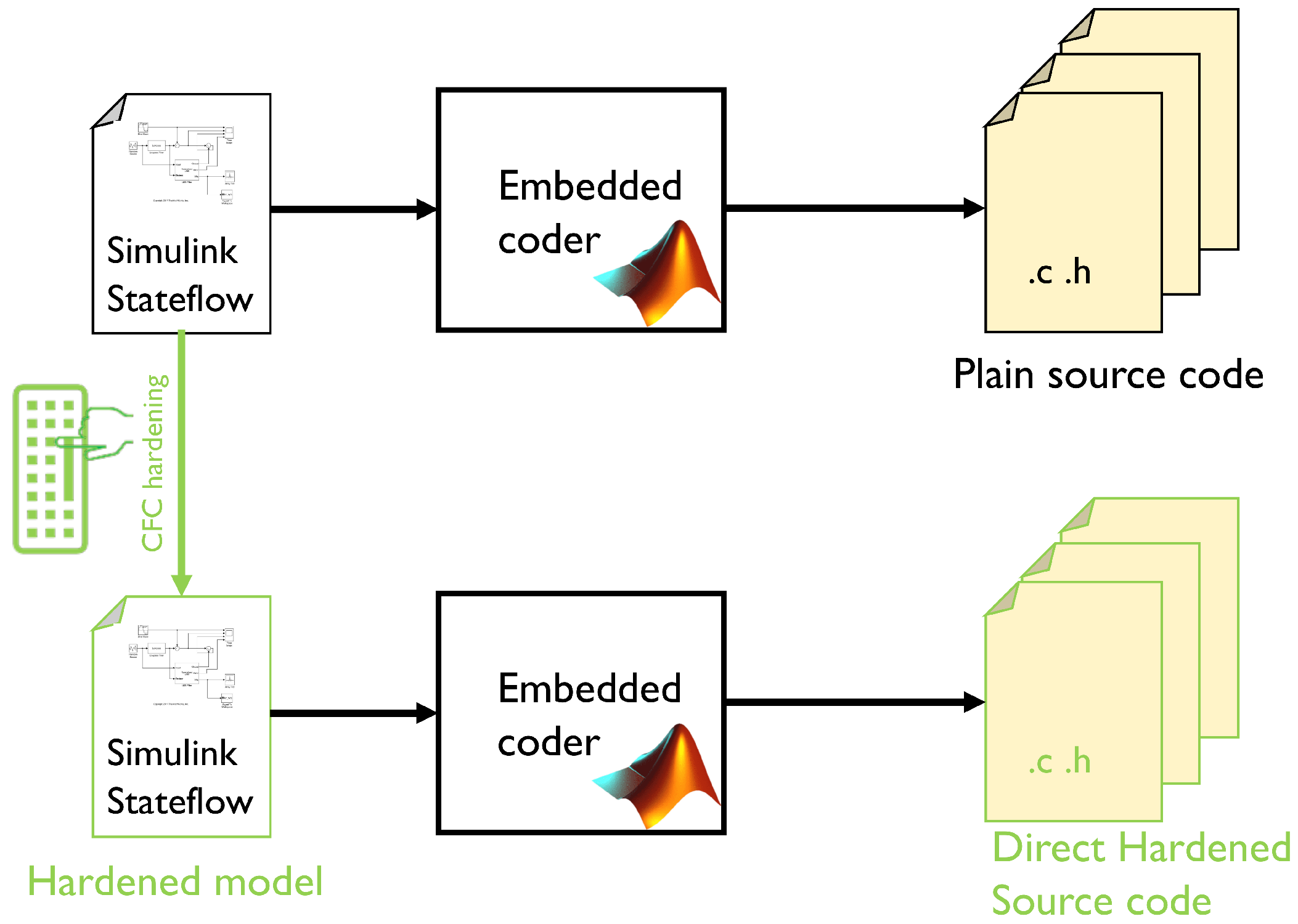
We chose YACCA and RACFED since they are based on different philosophies (bit mask vs. random numbers, only inter-block vs. intra-block detection capabilities). Due to these two different philosophies, we chose YACCA due to its extreme simplicity of implementation, and RACFED since it is the most recent. To harden the code, we instrumented CFC techniques by hand into the Simulink model representing the application behavior because, in the automotive industry, the software is usually developed by the model-based software design approach. Moreover, based on functional safety requirements, it is not recommended to implement by hand on the assembly code. Regarding our approach, the hardened C code was obtained from the code generator Embedded Coder. In this way, modifications of the code generator are not needed since it generates the source code and CFC directly from the behavioral model. This worsens the impact on the granularity since statements are added not only once (by the compiler), as if the C code has been hardened by hands, but twice: by Embedded Coder translating the model in C, and then by the compiler. From this observation, there is a need to measure the detection rate experimentally.
To assess our proposal, we implemented YACCA [
15] and RACFED [
19] to compare two different CFC algorithms. The first is based on bitfields, assigning a single bit signature to each BB and lacking intra-block detection capability. On the other hand, the latter uses signatures based on random numbers and features intra-block detection.
The advantage of YACCA is its implementation simplicity usually (in assembly and C language) leading to small overheads in both instructions and code terms, but it requires a signature variable with a bit width equal to the number of BBs. It can be challenging to implement them when there are more than 64 BBs.
RACFED is a more complex method, but due to the usage of random numbers, it can use a smaller signature (64 bits are sufficient in every case). Moreover, for the reasons mentioned above, it shall provide better detection capabilities from a theoretical point of view.
The metrics measured on our benchmark application are available in
Table 2.
Moreover, these methods have not been implemented through a traditional high-level programming language (such as C, C++, or ADA), but resort to a graphical representation of its functionality in the form of a physical/control model or a finite state machine (FSM).
The common adopted tools used to develop these models are the ones developed by the company MathWorks [
25].
Their popular tool for describing behavior models is Simulink®, whereas its package StateFlow is used to develop FSMs. Since these are the most commonly implemented software units, CFC is perfect for hardening them against RHFs.
3.1. Fault Models
For the sake of this work, we considered only faults affecting the program counter (PC) register, directly or indirectly (for example, the control flow jumps to a location outside the program area or inside the program area but to a wrong address). We chose this register since it directly affects the instruction flow.
We used the tool presented in [
26] to perform the fault injection campaigns. The fault injection manager (FIM) described in the paper mentioned above features two fault models: first, “Permanent” and, second, “PermanentStuckAt”.
The “Permanent” affects only one bit of the register that remains from the injection fixed to 0 or 1, whereas the “PermanentStuckAt” affects the entire register globally, making it stuck to a fixed value. Here, we used only the “Permanent”, choosing the injection time, the affected bit, and its state randomly.
It is possible to choose a subset of bits that can be affected by a bitmask to increase the injection efficiency. Considering that the benchmark application is a small embedded software (in this case, some tens of KBytes, but usually no more than some MBytes), in order to increase the fault injection campaign efficiency, we decided to avoid injecting on higher bits. This is considering that such injections would cause the PC to immediately move outside the small (with respect to the addressable space) .text area, triggering hardware failure detection mechanisms.
We chose the “Permanent” faults because, if we injected a “PermanentStuckAt” fault on PC, we would only obtain the effect of the processor becoming stuck, thus preventing the CFC from detecting the errors.
In more detail, since we know that the RV32I has 32 bit long instructions and that it addresses blocks of 8 bits (for a total addressable memory of Bytes = 4 GBytes, we can consider that:
Injecting on the first two bits has no meaning since such an injection raises a hardware trap for misaligned memory access during the fetching of the instructions;
Injecting on bits more than the 11th or 12th has no practical meaning due to the small flash memory installed on embedded systems.
Thus, we decided to start from the third bit, considering that the number of “skipped” instructions when the fault-affected bit at a position N assumes the wrong value is equal to . For example, if the sixth bit is affected, it provokes skipping instructions.
The higher bit of the mask was chosen by considering the benchmark .text area size as indicated in
Section 4.
3.2. Implemented Software-Based Hardening Technique
Simulink allows for code generation starting from models by using Embedded Coder. This process allows C, C++, optimized MEX functions, and HDL code to be easily generated. The Target Language Compiler tool (TLC) is included in Simulink, allowing the developer to customize the generated code accordingly to the requested platform starting from any model. It is used to convert the model into C code. Our proposal is shown in
Figure 1.
We chose these techniques (YACCA and RACFED) for our empirical study.
3.3. YACCA
The yet another control-flow checking using assertions (YACCA) technique is an inter-block CFC, and was proposed in [
15]. It assigns two unique compile time variables. The first variable is a
, and the second one is ERR_CODE. ERR_CODE is initialized to zero. In more detail, at the compile time, a unique
is assigned to each BB; consequently, to each one of them, a signature corresponding to
is assigned (to have only one 1 in binary representation). At the beginning of the execution, the
equals the first BB’s
. At the run time, when the program enters into a new BB, a check function is executed. It compares the current value of the
with the bit-wise NOT of a mask composed by the sum of all of the
mask of its legal predecessors. Since the signature shall contain only one bit corresponding to a legal predecessor, the result of this operation shall be zero. Otherwise, the signature contains at least one bit set to 1, representing an
of a BB that is not a legal predecessor. In this case, the ERR_CODE increases by 1 to indicate the presence of a CFE. When the BB ends, the
is updated by a set function. Before jumping to the next one, it resets the
content by performing an AND operation between
itself and a mask corresponding to the bit-wise NOT of
, and then OR with the
of its legal successor. As for the test operation, the
is set to all zeros by the AND operation (if the
is the correct one, the bit-wise NOT of the current state
is also the bit-wise NOT of the
, and hence
NOT
= 0) and can be set to the
of its legal successor by the OR operation. If a CFE happens, the AND followed by the OR operations set two different bits to 1, so none of the BBs can successfully pass the comparison between
and its
, causing ERR_CODE to increase.
3.4. RACFED
There are four steps in the process of implementing RACFED:
First, all of the needed signatures are defined at the compile time. For each one of the BB, these are the compile time signature (CTS) and subRanPrevVal. If there are more than two payload instructions inside the considered BB, a random number is assigned to each one of them. The CTS is a random number representing the expected signature value. subRanPrevVal is the sum of all of the chosen compile time random numbers previously assigned to the payload instructions. In the case of BB with instructions, subRanPrevVal .
Consider now the execution of a BB after the signature check. The run time signature (RTS) is increased after each payload instruction of the random value assigned to it. This allows for the detection of intra-block CFEs.
Next, at the end of the considered BB (all payload instructions have been executed), an adjustment value is computed as the sum of its CTS and the sum of all of the random numbers assigned to its payload instructions (independently computed at run time), and then by subtracting the CTS and subRanPrevVal of its successor BB.
Now, the RTS of the yet computed adjustment value is increased.
Finally, at the beginning of the successor BB, RTS is updated (concluding the two-phase RTS update) by subtracting the subRanPrevVal of its predecessor BB, making it equal to the CTS. If no CFEs happened, this equality is verified, and the process repeats over and over again from the step 2.
4. Experimental Results
In order to assess the diagnostic coverage obtained with YACCA and RACFED implemented by the MBSD, we hardened the benchmark application with CFC techniques and validated them with the performance assessment system described in [
26]. In this study, we opted for two benchmarks: (i) timeline scheduler (TS) and (ii) tank level (T). The first benchmark is a finite state machine (FSM) that implements a timeline scheduler. A timeline scheduler is a periodic task, executed thanks to a timer triggering an interrupt, in charge of running a set of tasks in a fixed order defined by the system designer. In our benchmark, we have 15 tasks that shall be executed in a fixed order, granting each of them a 200 ms time slot.
Since the scheduler is a needed core component, we chose this application as a case study. In particular, the timeline is the simplest one that is possible to implement in order to allow for more than one task to run into an embedded system, allowing us to share the computation unit between different applications. The second one is a software-implemented controller in charge of keeping the liquid level contained in a tank at the desired height with an on–off logic. It takes the liquid level inside the tank alongside the current absorbed by the pumps. Based on the measured liquid level, it decides when to turn the pump on and generates an alarm in case of the detection of over-currents, shutting down the pump to avoid damage to its motor.
As this application is widespread in the automotive industry, developers can extend its idea to other applications, such as the estimated battery level, which is a crucial feature in modern hybrid cars.
We prepared implementations on the source code that was generated directly from the Simulink Stateflow chart via Embedded Coder.
Such a benchmark application was chosen since this kind of algorithm is expected in the automotive environment; for example, battery management during regenerative braking or in other functional safety environments to keep the right level in fire extinguisher plants.
4.1. Target Platform
The target platform, as described in [
26], is RISC-V RV32I, simulated at the instruction-set level thanks to the Quick Emulator (QEMU) [
27]. It is an open-source machine emulator and virtualizer written by Fabrice Bellard. Most parts are licensed under GNU General Public License (GPL), and others under other GPL-compatible licenses. The main reason for why QEMU was used in our proposal was to make the test bench agnostic concerning the specific instruction set, since it can emulate many different ISAs.
The Gnu DeBugger (GDB) was used to interact with QEMU. GDB is an open-source debugger suitable for various programming languages, such as C. The fault injection is managed by a fault injection manager that writes the GDB scripts needed to inject the faults.
4.2. Fault Injection Results
The main idea of this classification is to describe the behavior of the application after the fault has been injected [
26].
To carry this out, seven possible outcomes were defined:
“Latent after injection”: fault injected and behavior identical with regard to the fault-free run.
“Erratic behavior”: behavior different with regard to the fault-free run.
“Infinite loop”: PC moves in an infinite loop not present in the original program flow but created by the interaction between the source code and the defective PC register.
“Stuck at some instruction”: PC remains stuck pointing to a valid instruction.
(Detected) “by SW hardening”: detected by the software hardening mechanism.
(Detected) “by HW” (mechanism): PC pointing outside the FLASH/RAM addressing space.
“As golden”: detected and with an output identical to the golden run.
Moreover, the four other outcomes—“latent”, “error”, and “undefined”, not related to the application by itself but inserted to monitor the classifier, and the “false positives” of the detection algorithm—are provisioned. We conducted four campaigns, each one with 1000 injections of a “Permanent” fault affecting the program counter (PC) of the target.
All of the faults were injected into the PC since the CFC can detect only those FMs directly or indirectly affecting the program flow. Considering this known limitation, we know, without any need for experimental results, that those affecting data or making the program follow a wrong but legal (present in the CFG) path are not detected; for example, choosing a wrong path on a conditional assertion (e.g., if-else) due to corruption on the variable to which the condition will be applied.
The results obtained from the classifier for YACCA implemented on the timeline scheduler are available in
Table 3 and, for the tank level, in
Table 4. Moreover, the results obtained for RACFED for the same benchmarks are reported in
Table 5 and
Table 6.
4.3. Diagnostic Coverage
To obtain diagnostic coverage (DC), two steps are needed.
In the first step, it is necessary to express the simulation results, shown in
Section 4.2, in terms of “detected” if an embedded mechanism can find the presence of the considered RHF, or “undetected” otherwise.
Considering the “detected” class, it is possible to split it into two subclasses:
“safe” if the RHF cannot have dangerous effects on the user of the item or the surrounding environment;
“detected” if it is not possible to make such an assumption (like in the case of this paper, where the mitigation strategies are not considered).
On the other hand, also considering the “undetected” class, it is possible to define two subclasses:
A third (not defined by the ISO 26262) subclass, called “false positive”, was defined to describe the probability that the detection mechanism is wrongly triggered. In any case, on an excellent detection mechanism, the frequency of this subclass is 0%.
The results expressed in these terms, now ISO 26262-compliant, are presented in
Table 7. From this table, it is possible to perform the second step to compute the DC.
We considered as “detected”:
All of the faults that ended up with detection by the software;
Those that caused a timeout after the last SET instruction (miming the behavior of a windowed watchdog);
The one detected by the hardware (PC pointing outside the limits of the instruction memory).
For YACCA, we obtained a DC of 51.8% for the timeline scheduler (TS) and 1.86% for the tank level (T).
For RACFED, we obtained a DC of 70.0% for the TS and 4.34% for T.
Regarding the CFC algorithms that we opted for, we can say that RACFED is more effective than YACCA. This is an expected result since it also provides, alongside intra-block detection not exploited in our benchmark, a two-phase signature update.
For both cases, it is evident how the DC lowers for the T benchmark compared with the one obtained on the TS due to both algorithms’ different natures.
The TS, due to its scheduler nature, performs a state transition every time its step() function (the function that is called at a fixed rate to make it behave as a periodic task) is called, whereas this is not true for the T, since its transitions depend on the level of the liquid inside a slow-changing physical system (a tank), leading to a relatively lower number of transitions.
Analyzing the experiments where the CFC is not able to detect the injected failure (infinite loop or stuck at some instructions results in
Table 3 and
Table 5), it is possible to observe a known limitation of those algorithms experimentally. Since the application and the CFC are executed on the same computation unit, no detections are possible if the error prevents the TEST instructions from executing. In the ISO26262, these cases are indicated as not “free from interferences”, since the same root cause can affect both. This is an important point when designers choose to adopt such solutions, since CFC by itself is incapable of detecting 100% of faults: this highlights the need to combine this type of algorithm with other techniques, such as watchdog or the execution of tests on other cores if they are available.
The last observation is that there are no “Infinite loop” or “Stuck at some instruction” outcomes for the T benchmark. This, alongside the very high rate of “Latent after the injection” with respect to the TS results, shows how the nature of the application to be hardened is essential in a real use case: if no change in decision is needed in the time window between the injection and the end of the simulation, the behavior remains accidentally correct.
A possible proposal for such applications, in the case of sufficient spare execution time, can be to add a dummy control flow to check if the computation unit is working correctly. This solution can be adopted when an online test is unavailable for the target platform, or the application should not depend on any specific platform for commercial or intellectual property protection reasons.
4.4. Overheads
Table 2 presents the data on the overhead of the hardening techniques considering two different aspects: the increase in the program size (evaluated in terms of the increase in its text segment) and the number of actually executed machine-code instructions (a reliable metric to estimate its effect on its execution time).
It is possible to see that the explanation on the lower DC for the T benchmarks is confirmed considering the overhead in terms of the executed instructions number: for both the hardening techniques, we have a stronger impact. This result is expected: the more the signature is tested, the greater the probability that it detects CFEs. Considering the T benchmark, the impact of the CFCs in terms of executed instructions is almost negligible (a small number of BBs transitions happen).
The huge difference in terms of text segment sizes between the two benchmarks can be explained in terms of the number of BBs present: the functions related to the hardening techniques are implemented with the inline option of Embedded Coder, so a greater number of BBs requires, in a proportional way, more C language statements and then more machine code ones.
Regarding the main memory occupation, our implementation of the YACCA algorithm requires three unsigned 64-bit variables for a total of 24 bytes for each execution flow. The TS has only one execution flow, whereas T has two execution flows (one for the decision based on the tank level, the other to implement the overcurrent protection) with an occupation of 48 bytes. Considering RACFED, it needs four 64-bit variables for the execution flow. Hence, the overhead is 32 bytes for TS and 64 bytes for T.
5. Conclusions
This paper has presented the diagnostic performances of two case studies.
Following a model-based software design approach, the hardening against RHFs was implemented at a high level of abstraction directly into the behavioral models, and then automatically translated to a high-level language (in this case, C). This allowed for the implementation of the CFC directly within the Simulink Stateflow environment.
For this study, we considered YACCA and RACFED as the CFC algorithms. These allow the program behavior to be observed with effective and cost-efficient error detection.
Table 7 demonstrates that the diagnostic coverage (safe + detected) achieved depends on the nature of the hardened algorithm. If the number of BB transitions increases, the CFC methods can more efficiently detect RHFs.
The TS performed transitions continuously, reaching a DC of 51.8% for YACCA and 70.0% for RACFED. On the contrary, for the T benchmark, where only external events trigger the transitions, the DC dropped to 1.86% and 4.40%, respectively. In both cases, RACFED performed better than YACCA.
Another evident phenomenon related to the TS benchmark shows that the executed instruction overheads for the CFC methods (both YACCA and RACFED) were similar to the assembly level (obtained from the literature and reported in column EO of
Table 1). For YACCA, we observed + 170% in the MBSD implementation and + 203.2% in the assembly experimental, whereas, for RACFED, +87.7% and +81.5%, respectively.
This empirical study of CFC could benefit software developers and researchers, especially those involved in the automotive industry, in identifying the most appropriate techniques for RHF detection. Of course, an accurate analysis shall be conducted to guarantee sufficient freedom from interference as required by the ISO26262 standard.
In future works, we would like to analyze and benchmark different implementations of these algorithms on a multi-core system or by resorting to external hardware. Another point can be to compare the effectiveness of dummy execution flow for cases similar to the T benchmark compared to a state-of-the-art online test.


