Article

Buckling Analysis of a Thin-Walled Structure Using Finite Element Method and Design of Experiments

by
Mohamad Norfaieqwan Bin Kamarudin
1,
Jaffar Syed Mohamed Ali
1,*,
Abdul Aabid
2,* and
Yasser E. Ibrahim
2
1
Department of Mechanical and Aerospace Engineering, International Islamic University Malaysia, P.O. Box 10, Kuala Lumpur 50728, Malaysia
2
Department of Engineering Management, College of Engineering, Prince Sultan University, P.O. Box 66833, Riyadh 11586, Saudi Arabia
*
Authors to whom correspondence should be addressed.
Aerospace 2022, 9(10), 541; https://doi.org/10.3390/aerospace9100541
Submission received: 13 June 2022 / Revised: 6 September 2022 / Accepted: 14 September 2022 / Published: 23 September 2022
(This article belongs to the Special Issue Recent Advances in Technologies for Aerospace Maintenance)

Abstract

:
In structural engineering, thin-walled structures play an important role in the design of the lightweight structural model. It carries different loading conditions when it exists in any model, and it is designed with thin plates or thin shells. Penetrating thin-walled structures with different kinds of holes can decrease their weight and facilitate repair and maintenance operations, such as those carried out for the wing of an airplane. In such applications, cutouts are often employed as part of the design of composite plates. Therefore, this paper attempted to design and analyse the thin-walled composite structure with a C-cross-section shape. To model and analyse the structures, a finite element method was utilized using the ABAQUS commercial tool, and the results of critical buckling load for different laminate types were obtained. Composite materials and structures have different parameters that can vary the results of analysis; therefore, to optimize the current mode a design of experiments method is used via MINITAB 20 and Design-Expert 13 tools. The selected parameters for this work were the opening ratio, spacing ratio, and shape of the hole for the output response as a critical buckling load was carried out. Based on the current results of simulation and optimization, it was found that the parameters of composite materials and structures will impact the output response, and the current study investigated the optimum parameters for the best possible outcome of the structural analysis.

1. Introduction

Thin-walled structures are applicable for different engineering applications, such as in aerospace, automotive and construction industries, and they have played an important role in reducing the total weight of structures. One of the systems with the most efficient use of materials to prevent buckling is the thin-walled member because it is made up of several thin-walled parts. The thin-walled portion can easily be formed into various shapes with a high shape factor while using less material. However, the thin-walled member has significant disadvantages associated with its formed plates, such as local buckling. The composite plates of the member usually buckle before collapse when a thin-walled column is subjected to compressive loading [1]. Various shapes of the thin-walled structure can be used to suit its application in the mentioned industries. For example, some studies have shown T-shaped thin-walled structures considering various geometries, which are used in aircraft as ribs [2,3,4,5]. Furthermore, Rozylo and Debski [6] experimented on the Z shape of the thin-walled composite structure and showed the enhancement in improving the structural performance of the whole model.
Generally, buckling is a typical phenomenon in thin-walled structures. It is a term that refers to a component’s lack of stability caused by the lateral deflection on a member when an axial force is applied. The weakness of the column causes it to bend. This mode of failure is rapid and, therefore, risky. The length, strength, and other variables of a column determine whether or not it will buckle. Elastic buckling can occur in long columns relative to their thickness [7]. It can also occur when an applied compressive load exceeds the critical allowable load of the thin-walled structure. Pre-buckling, critical buckling, and post-buckling are the three major states that describe a standard thin-walled composite structure. Buckling and carrying capacity determine the proper loading process of the structure. The structure can still function even after buckling because the post-critical equilibrium trend is stable, and the increasing compressive load increases the wall deflection [8,9]. 
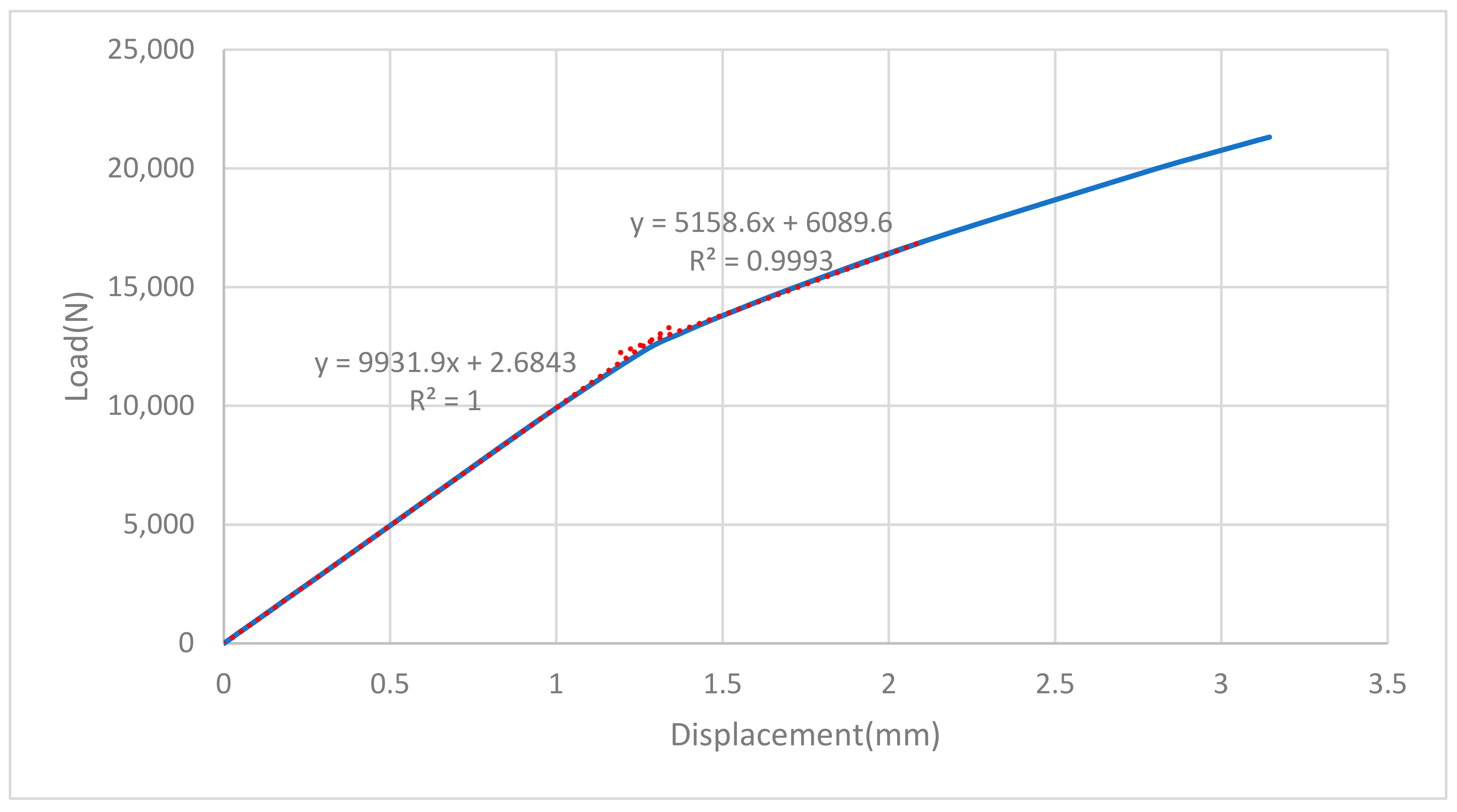
Figure 1 below shows the state of each operation for a thin-walled structure.
Figure 1. Graph of load applied versus deflection [9]. Reprinted under the Creative Commons (CC) License (CC BY 4.0).
Aerospace 09 00541 g001
Damaged/holed thin-walled structures have become more prominent in recent investigations, and the reason for failure of the whole structure has been found. Composite materials are widely used in the aerospace and automotive industries due to their advantages, such as their lightweight nature and high strength ratio as compared to other types of materials. In recent investigations, composite materials have been utilized in a wide range of applications in response to the growing need for lightweight and efficient structures. Therefore, it is necessary to investigate the influence of the various sizes, shapes, and distances between cutouts of thin-walled composite structures on buckling and other behaviours. This study continued from the study conducted by Khazaal et al. [10], in which the authors used aluminium alloys as the subject of the experiment. Three types of shapes, circular, hexagon, and rectangular, were chosen to optimize the results. They also studied the parameter that contributes most to the buckling behaviour of the aluminium alloy thin-walled structure.
The FE method was used to explore the stability properties of folded structures and analysed the buckling behaviour under a compression load, shear load, and combinations of both loads with varied boundary conditions. As a result, critical buckling loads for open- and closed-box structures with varying loading conditions were investigated [11]. It has been stated that the newly proposed transverse extension modes have a practical advantage in that the increased artificial stiffness that results from constrained assessments of pure global and distortional deformations can be offset by taking into account the appropriate new transverse extension modes in thin-walled structures [12]. For axial–flexural buckling, post-buckling, and geometrically nonlinear studies of thin-walled beams, an effective one-dimensional FE method using a novel structural concept known as equivalent layered composite cross-sectional modelling was proposed, in which nonclassical factors such as transverse shear and normal flexibilities are included in the formulation [13]. A brand-new beam-type FE method has been developed that may be used for web distortion and elastic buckling analysis of thin-walled beams. Under the premise that there are no pre-buckling deformations, the buckling formulation was created based on nonlinear equilibrium equations [14].
The load-bearing capability and involvement of stress components in the failure analysis of top-hat-shaped composite columns exposed to uniform compression and utilized a digital image correlation (DIC) technique to see the full-field displacements and strains, and failure tests were conducted across the whole load range [15]. For the geometrically nonlinear analysis of thin-walled circular pipes, the formulation of generalized beam theory was used, and the complete geometrically nonlinear analysis was added to the existing generalized beam theory analysis of circular pipes, which is currently confined to buckling analysis [16]. A new technique called the finite strip–Riccati transfer matrix method was established for buckling analysis of thin-walled components with a tree-branched cross-section. The procedure combines the semi-analytical finite strip approach with the Riccati transfer matrix method for a tree multi-body system [17]. To calculate the changes in beam stiffness due to the decrease in thickness in the pre- and post-buckling stages, a nonlinear FE model of a thin-walled beam with variable thickness was introduced. The gauge sensitivity of the beam was then calculated using these stiffness values, and it changed as the beam thickness changed [18]. Residual stresses in thin-walled structures manufactured by the directed energy deposition method were determined; additionally, in situ measurements, fast thermo-mechanical simulation, and buckling were investigated through the experimental and numerical approach [19]. Buckling analysis of thin-walled metal liners of cylindrical composite overwrapped pressure vessels with depressions after autofrettage processing was investigated through the FE approach [20]. Similarly, large deflection and post-buckling of thin-walled structures by finite elements with node-dependent kinematics [21] were investigated.
Sudhirsastry et al. [22] stated that composite materials have been widely used in the automotive and aircraft industries for plates and shells due to their high strength-to-weight ratio and stiffness-to-weight ratio. Due to the widespread usage of composite structures in the form of relatively thin plates, the load-carrying capacity of composite plates against buckling is crucial. Additionally, cutouts are frequently used in composite plates as part of the design of the structures. As a result, it is critical to have a firm grasp of the buckling properties of composite plates with cutouts. Erkliǧ and Yeter [23] found that for composites with a thin-walled, fibre orientation, the angle of the cutouts, the plate size, and lastly the size of holes result in an effect on the buckling behaviour. Nevertheless, the parameter that contributes most towards the behaviour of the buckling of the holed composite plate is not identified. This, together with the work conducted by Khazaal et al. [10], has ignited the motivation to carry out the present study to contribute to the knowledge on thin-walled structures with cutouts specifically for composite material.
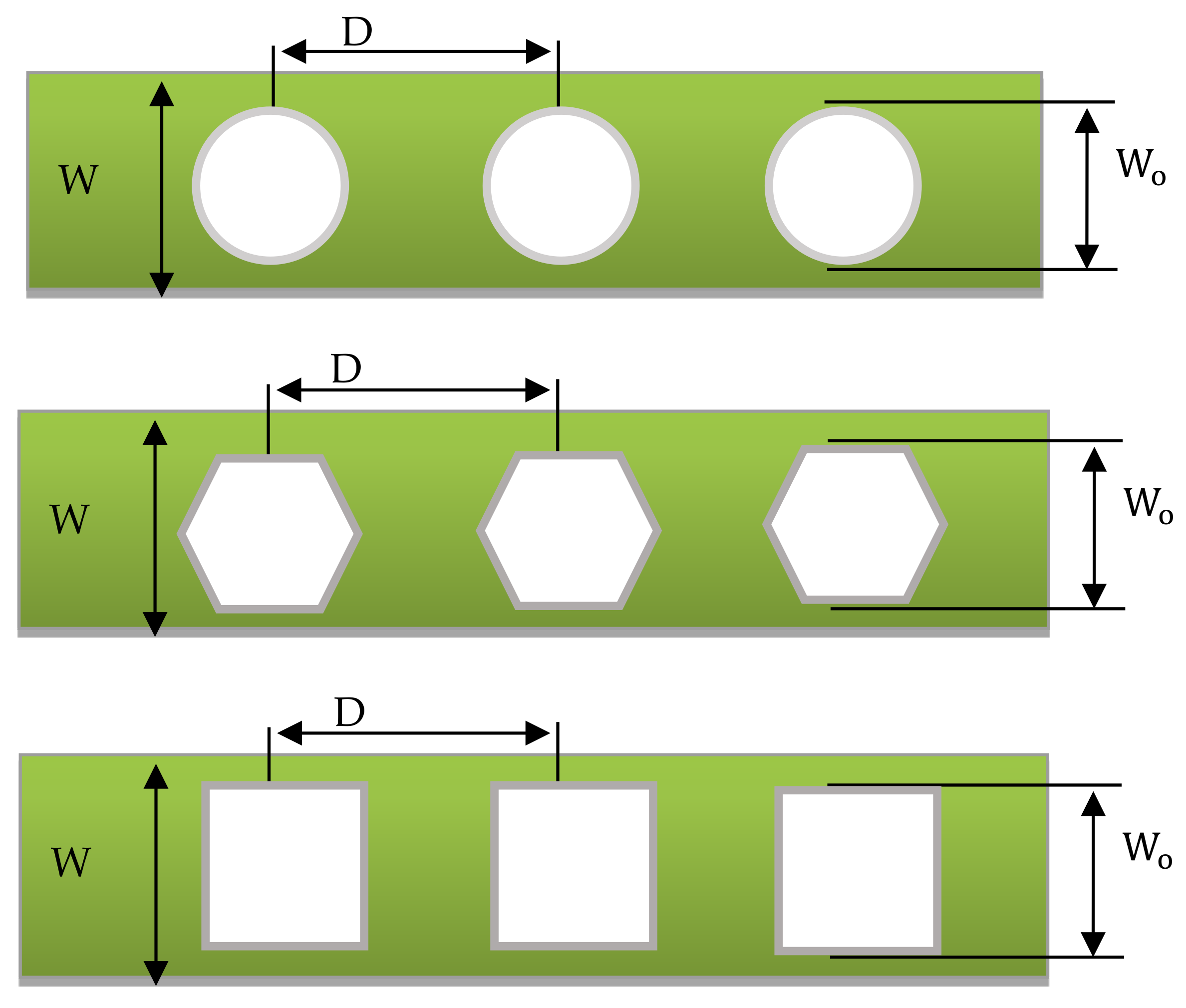
The main objective of the current study was to use glass-fibre-reinforced polymer as a composite material. Different laminate types were tested using ABAQUS software upon verification of the work of [24]. The laminates used were quasi-isotropic (0/90/45/−45)s, angle-ply (45/−45/45/−45)s, cross-ply (0/90/0/90/0/90/0/90), and balanced laminate (−45/30/60/30/−30/45/−60/−30). In this study, the implementation of the design of experiment (DOE) seemed necessary to ensure that all parameters affecting the buckling load were optimized. We began with identifying the factors and levels followed by selecting a suitable factorial design. This study used a full factorial L
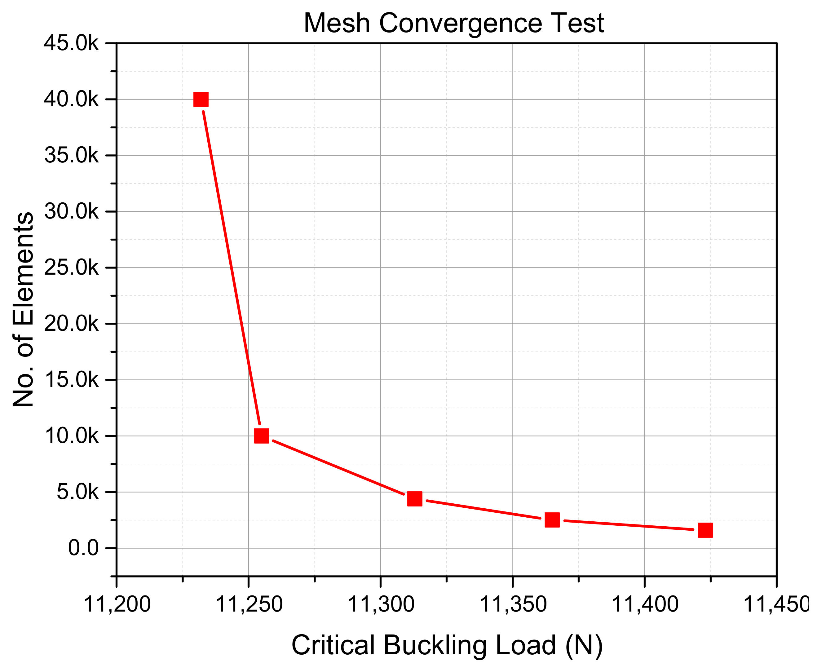
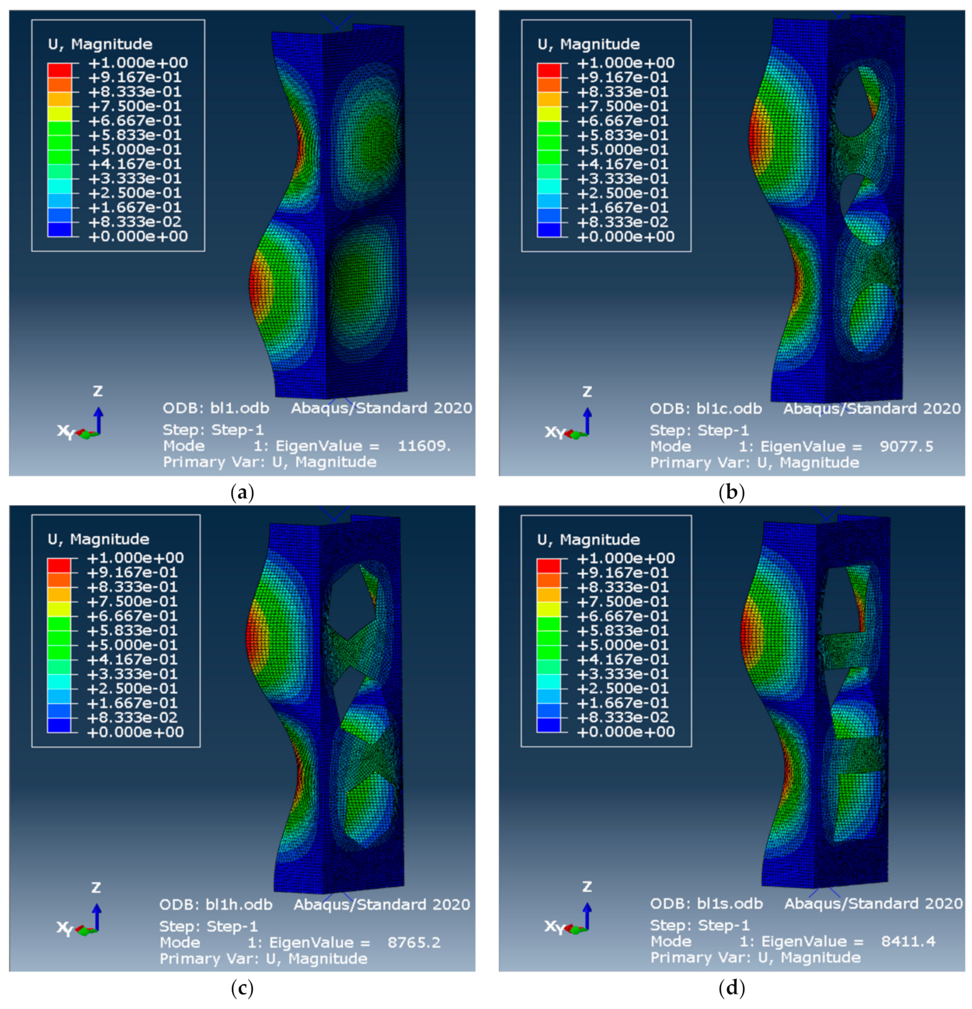
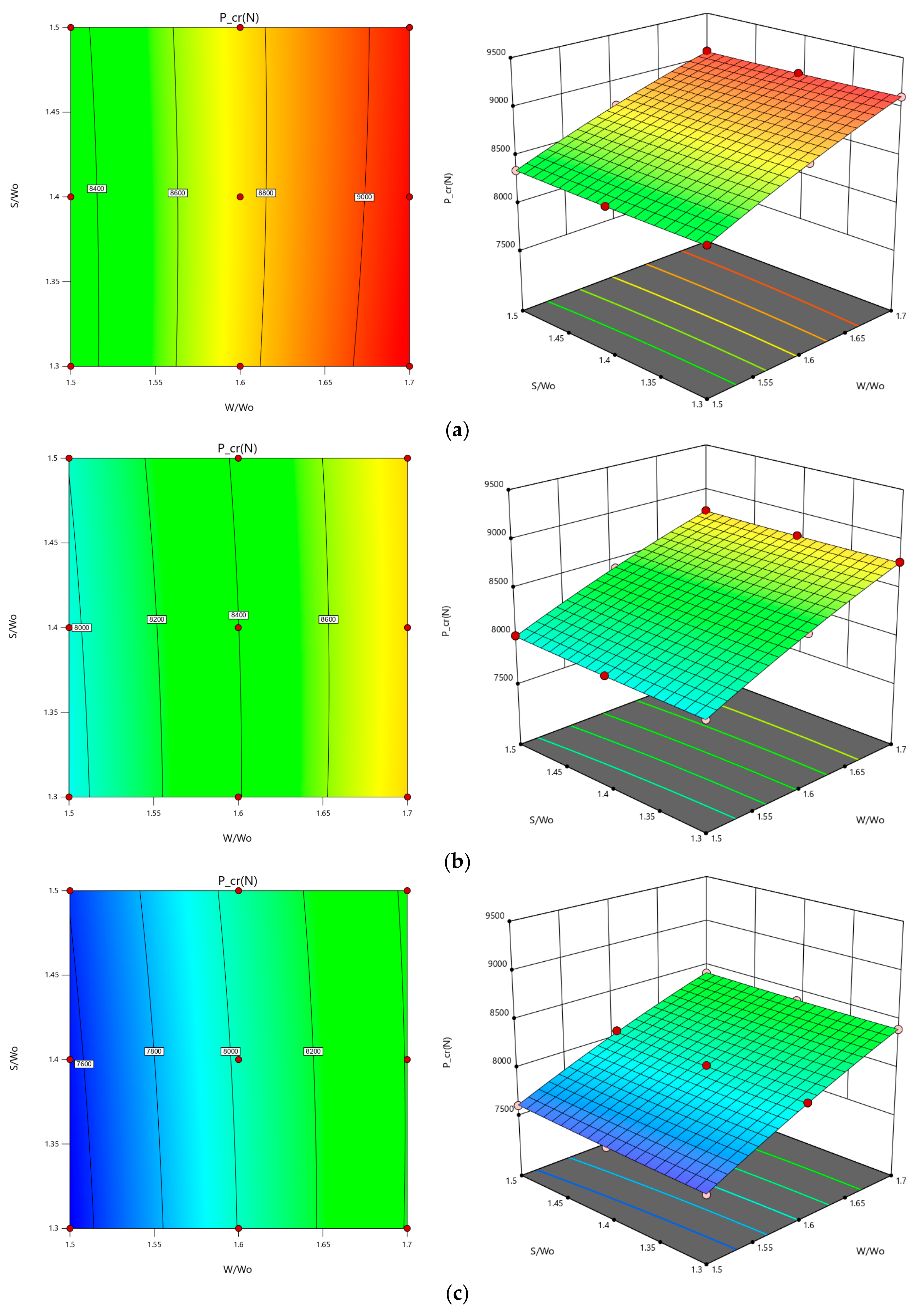
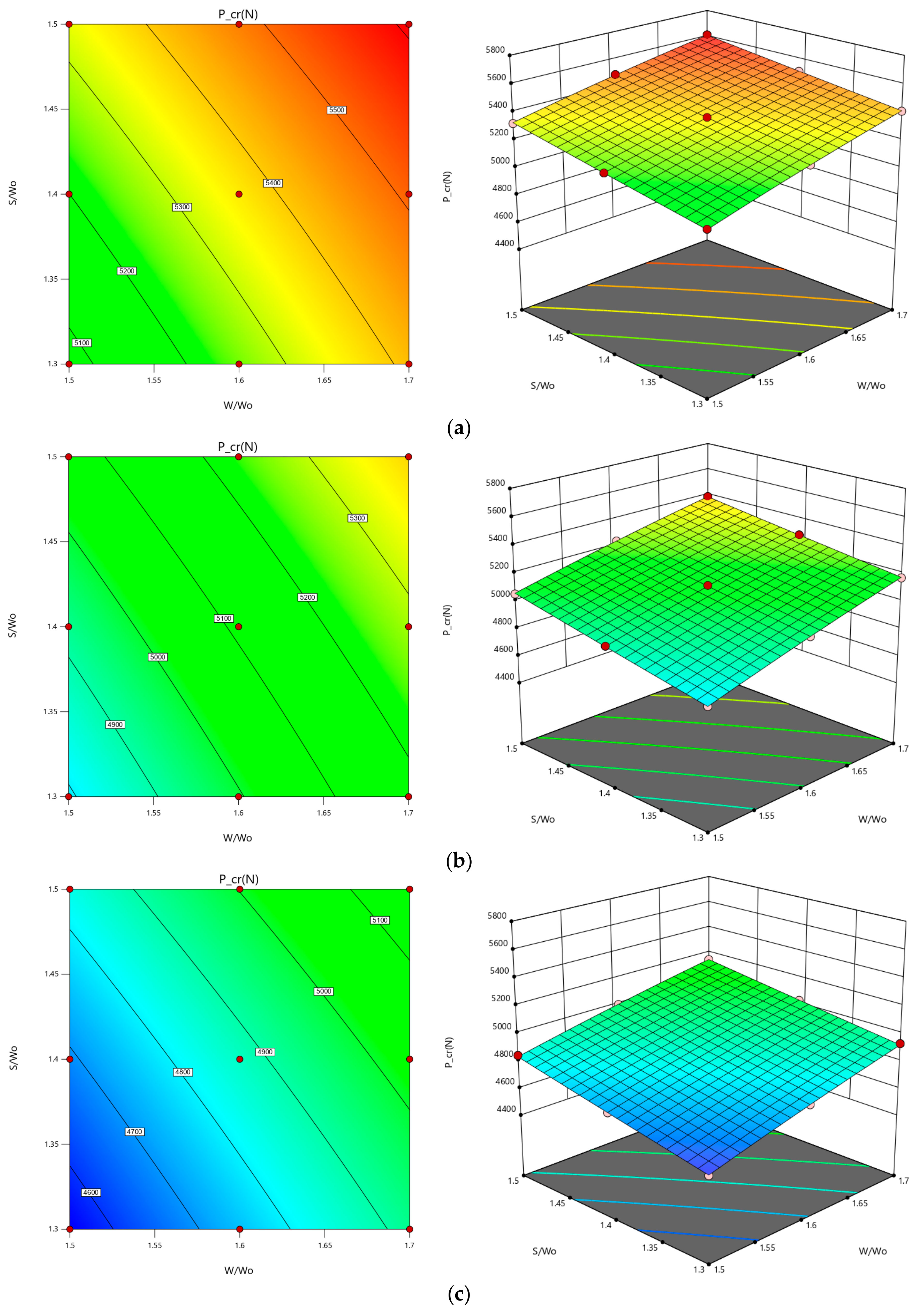
27 orthogonal array where 27 indicates the number of runs (simulation) required. Response surface methodology (RSM) was used to analyse the obtained data through the main effect plot, contour plot, regression, and analysis of variance (ANOVA). Additionally, the present study focused on perforated composite plates, and the supports were fixed at both ends and the orientation of the fibre was as mentioned. The cross-sectional shape considered was a C section. The novel work of this study focused on optimizing the parameters to achieve the highest probable critical buckling load for perforated composites and thin-walled members, through simulation using MINITAB and Design Epxert tools.

2. Finite Element Method

2.1. Designed Model

The model was considered a C-section channel, and the dimensions of the model are included in Figure 2. The material was glass-fibre-reinforced polymer (GFRP), which is shown in the model, and the channel had the following dimensions: a height of 80 mm, a width of 40 mm, and a length of L = 250 mm. The flanges and web had a thickness of 2.08 mm and were made up of eight 0.26 mm laminated layers. The same dimensions were used for subsequent analysis for four types of laminate, named quasi-isotropic, angle-ply, cross-ply, and balanced laminate. In the present work, the model had eight layers of GFRP material [24], and these properties were initialized into ABAQUS software. Additionally, the GFRP material had a mass density of 2200 kg/m3. Table 1 shows the GFRP strut’s strength properties.

2.2. Loading and Boundary Conditions

The current simulation model was developed in ABAQUS software. All mechanical properties can be input into the engineering data before the other step. The size of the mesh was 2 mm and was used based on mesh sensitivity analysis. To have fixed-fixed end supports, all points on the bottom end had restrained rotations (ROTX, ROTY, ROTZ) and translations (UX, UY, UZ). On the upper part of the column, the load was applied at the reference point, which is shown in Figure 3. RP-1 represents the reference point at the bottom, while RP-2 is for the top section.
The buckling analysis of the linear perturbation procedure in ABAQUS was used for the elastic buckling analysis. All models utilized multi-layered, four-node elements, S4R, where each node has six degrees of freedom. The S4R shell is a four-node stress–displacement element with reduced integration. With this element, thin-walled structure geometry is expressed by a flat finite element degenerated from 3D finite element formulations of the structure’s mid-surface [24]. The x, y, and z rotation angles of the upper end were all assumed to be constrained (Figure 4). The vertical z axis was set to be unrestricted, while for the bottom end, at the reference point, all degrees of freedom were restrained. Using rigid body-pin (node) constraints, a uniform load was applied to a reference point that represented the upper nodes of the strut. The contact of the strut with the top plate is represented by this type of constraint. The FE model was given a nominal compressive load of 1.0 N. A linear eigenvalue buckling problem was used to determine the critical buckling load. The first buckling mode, which is referred to as the critical buckling load, was used in this study to generate the buckling mode shapes.

2.3. Laminate Model

The GFRP laminate in this study consisted of eight layers of unidirectional fibre-reinforced laminate. It was decided that the laminate would be a quasi-isotropic material that would have symmetrical layups using a (0/45/45/90)s stacking sequence. When subjected to loading in the plane of the laminate, this material results in the laminate behaving in the same manner as an isotropic surface [24]. The boundary condition has a significant impact on the buckling load of any engineering structure subjected to a uniformly compressive in-plane load. There is no lateral displacement or rotation along the edges if all sides of the plate are fixed, so it is more stable than simply supported [25].
In the ply system (x′, y′, z′), or the local axis system, a single laminate can be thought of as an orthotropic layer (Figure 5). The way the fibres are arranged makes an angle with the global coordinate system of the composite plate, and this angle is parallel to the local axis x′. The generalized Hooke’s Law can be used to figure out the relationship between stress and strain, which can then be used to understand the conditions of a quasi-isotropic laminate. For an individual lamina isotropic matrix, the extension and shear are ignored, and its parts do not depend on how the lamina is oriented [24]. This can be expressed as:
σ x σ y τ x y = Q 11 Q 12 0 Q 21 Q 22 0 0 0 Q 66   ε x ε y γ x y
where
Q 11 = E 1 1 v 12 v 21
Q 12 = v 12 E 1 1 v 12 v 21
Q 22 = E 2 1 v 12 v 21
Q 66 = G 12
The web and flange of the strut had the same overall thickness, which was set at 2.08 mm. The ABAQUS composite layup function was used to model the GFRP strut’s laminated composite geometry. To ensure that the web and flange of the strut had identical properties, the strut was made with the same number of plies, ply thickness, lamination stacks, and orientation of fibres, and this has been illustrated in Figure 6 and Figure 7. Both web and flanges had the same orientation of fibres on the model. Three parameters were considered, which were the spacing ratio, the shape, and the ratio of opening. For each parameter, three different configurations were introduced (Figure 8).
The shapes of the hole were circular, square, and hexagonal (Figure 8). The spacing ratio and opening ratio were selected as shown below.
1.08 < D W o < 1.5
1.25 < W W o < 1.75

3. Design of Experiment

In the early stages of work, the design of experiment (DOE) method was used, as a method utilized in various manufacturing industries [26,27] to investigate the factors that can help designers to reach their goals and reduce the human efforts. The parameters and their levels can be changed by the designer to achieve the optimum solution. For the factorial design, at least two parameters or levels must be used to change the elements, and this must be carried out after users pick a factorial design. The tests are conducted with the parametric combination and levels marked as orthogonal arrays for a chosen factor. Following the orthogonal array helped us to determine the effects of each important part. This allowed the analysis to be carried out, which showed which factors were most important for accomplishing objectives and how these could be changed to make them even better [26,28,29].

3.1. Plan of Experiments with FEM Results

To find the best possible response, the experiments were run using the full factorial design L27 orthogonal array provided by MINITAB-20 (Coventry, UK) and Design Expert-13 software (Minneapolis, MN, USA). If the orthogonal array degrees of freedom are greater than, or at least equal to the previous ones, then the test parameters and the array are selected. The current experiment’s parameters had a greater impact. An orthogonal array of 27 tests was used, and each row had a parameter assigned to it (each column had a row number). The simulations were carried out following the orthogonal array L27 standard. A planned analysis should be able to examine how different composite laminate types’ critical buckling behaviour was influenced by the opening ratio (W/Wo), spacing ratio (D/Wo), and cutout shape (Table 2).
Using the L27 orthogonal array, we were able to perform a linear buckling analysis for a variety of parameter combinations. Included here is the response for each laminate type as requested by Minitab and design expert software (Table 3).

3.2. Response Surface Methodology (RSM)

To obtain the best possible results when dealing with multiple quantitative variables, the response surface methodology (RSM) is one of the significant methods that can be used. In RSM, the dependent variables are referred to as responses, while the independent variables or factors are referred to as predictor variables. In contrast to the statistical significance test for a single point, RSM can be used to optimize variables or factors more practically.
The RSM can be used to figure out which parameters are affected by the many variables by using the smallest possible amount of effort, real proof, and a test design that works for every point of the response variable [26,28,29]. The RSM and the relationship between the factors stated were also used in this study to find the best setting for each one. By using an RSM analysis, we were able to determine the effect of shape, opening ratio, and spacing ratio on critical buckling loads for various laminate orientations. Additionally, Kumari and Gupta [30] stated that predictive models can be developed more accurately due to RSM’s ability to reproduce results and fine-tune processes. Response surfaces in RSM are graphical representations for describing the influence of process variables and their effects on response. Therefore, the present work considered an RSM to optimize the current problem with the selected parameters. Figure 9 below depicts the RSM process in more detail.

3.3. Analysis of Variance (ANOVA)

ANOVA analysis shows the impact of parameters and their relationships on the mean square and buckling load errors at predetermined confidence levels. Using the ANOVA, one can determine the impact of each factor on the overall variance in the findings [29]. Variance analysis is a technique for comparing models based on their resources. If the means of two or more groups differ significantly, this statistical analysis is used. The ANOVA measures the influence of one or more variables by comparing the methods of different samples, and it can be used to determine whether all treatments were equally effective. The ANOVA was used to determine the influence of each parameter on the critical buckling load.

4. Finite Element Results

4.1. Model Validation

This study used Doan and Thai’s [24] buckling results to verify the proposed FE model, and the specimen’s length and cross-sectional dimension were matched and reproduced by the same model to verify the current work. The quasi-isotropic laminate and angle-ply laminate FE buckling behaviour results were compared to the corresponding numerical analysis results in order to verify the accuracy of the proposed model. The stacking sequences (0/+45/+45/+45/+45)s and (+45/+45/+45/+45)s were used for the quasi-isotropic laminate and angle-ply laminate, respectively. To begin, the model of the beam without holes was compared for both laminates to have better reliability. Table 4 shows the comparison of numerical results for the critical buckling load with those of a previous study [24].
Table 4. Comparison of present results.
Laminate TypesCritical Buckling Load (N)Percentage Error (%)
Previous Study [12]Present Simulation (ABAQUS 2020)
Quasi-isotropic11,25811,2550.026
Angle-ply12,65211,3820.017

4.2. Mesh Convergence Test

To investigate the effect of meshing size, this study tested five different element sizes, which ranged from 1 mm to 5 mm. The element sizes that achieved the closest results were chosen for subsequent analysis. The mesh refinement was investigated considering a single case of current work which is similar to existing work [24], and we found the percentage error of 2 mm was close to the reference value. Once satisfactory results were obtained, the same mesh size was used for all models, and slightly modified mesh was used near the holes of the structure for smoothened mesh at the boundaries of holes. Referring to Table 5 and Figure 10, the element size of 2 mm had the lowest error, and the result started to converge at this element size. Additionally, the computing time was also quite reasonable for this mesh setup. This is necessary to justify that further refinement is unnecessary and the errors are minimized.

4.3. Displacement of Laminate Structures

The obtained results from the FE analysis prove that the introduction of holes reduces the ability of a beam to withstand axial load before it fails in this case, buckling for all types of laminate. The eigenvalue shown in Figure 11, Figure 12, Figure 13 and Figure 14 represents the critical buckling load that those models can handle before they start to buckle. For all models along the longitudinal axes, the flanges were deformed in a half-wave. This may occur as a result of the compressive stresses induced on the flange plane during the loading process. In the reference model (model with no holes), local buckling can be seen clearly along the web, while in the perforated models, buckling can also be seen near the edges of holes.
Referring to the attached Figure 11, Figure 12, Figure 13 and Figure 14, the angle-ply laminate had the highest value of critical buckling compared to the others despite the presence and shape of holes. Meanwhile, the cross-ply laminate was the weakest configuration among all laminates. All models experienced Euler buckling load with the first mode along the web and flanges. A consistent pattern of a half-wave could be seen despite the existence of perforation and its shape for quasi-isotropic and cross-ply. Hence, the difference in laminate configuration does impact the thin-wall structure’s critical buckling load and also the shape of buckling.

4.3.1. Effect of Shape

Figure 15 shows the effect of cutout shapes with different laminates for a constant spacing and opening ratio. The buckling load decreased as the cutouts were introduced. The circular cutout showed the highest critical buckling load, while the square had the lowest capability of buckling load. The decrement in the load seemed significant as holes were introduced. It is believed that this was due to greater area removal on the web of the thin wall with a circular shape, as this web had the least amount of area removed.

4.3.2. Effect of Opening Ratio

Figure 16 indicates a declining trend as the ratio of opening decreased. From Equations (2) and (3), one can observe that the size of holes increased as the ratio decreased. This finding shows agreement with the previous paragraph, where the buckling load was described to decrease as greater perforation was introduced onto the web of the thin-wall GFRP composite member.

4.3.3. Effect of Spacing Ratio

Lastly, in Figure 17, the graphs show an insignificant decrement in the trend as the spacing ratio decreased. For a constant opening ratio, one can deduce that the distance between the centre of two holes becomes closer as the ratio decreases. From all mentioned figures in this section, it was concluded that for all laminates, the circular, 1.7 opening ratio and 1.5 spacing ratio showed the highest critical buckling load. However, the effect of a combination of these parameters is discussed in the next sections. Furthermore, the cross-ply laminates had the lowest critical buckling load, as shown in Figure 15, Figure 16 and Figure 17.

4.4. Nonlinear Analysis

Additionally, nonlinearity was presented because of the material behaviour. The nonlinear behaviour of the structures was observed to ensure that the FE model is valid for further applications. A geometric imperfection scale of 0.1 was applied to the linear model, acting as a base state of the model before nonlinear analysis. Additionally, the node displacement derived from the linear buckling analysis was then applied to the initial deformation, and the first buckling load was allocated as the initial load for the post-buckling analysis model [24]. As seen in Figure 18. above, the path of post-buckling inhibited relatively stable bifurcation states. Hence, using the straight-line intersection method, a straight line was approximately plotted on both linear and nonlinear equilibrium paths, therefore introducing an intersection point representing critical buckling load [24]. The R 2 values on the figure above represent the coefficient of determination for the straight line based on scattered data for both pre- and post-buckling. The approximation equation portrayed was based on the applied load and displacement of the strut.
According to the obtained post-buckling analysis results, the quasi-isotropic model without holes had a critical buckling load of 12,086.53 N with a percentage of error of around 7.39% compared to linear analysis, which is still within the tolerance error of 10%. The other three configurations, which were angle-ply, balanced, and cross-ply, had a percentage of error of 0.3%, 0.03%, and 8.12%, respectively. All of them had a high determination coefficient for approximation of straight lines on both pre-buckling and post-buckling trends. Those R2 values indicate the accuracy of the approximation for a curved trend in a post-buckling state. Additionally, the critical buckling load for Figure 19, Figure 20 and Figure 21 was 12,667.85 N, 12,551.1 N, and 7878.47 N, respectively.

5. Optimization Results

5.1. Response Surface Analysis

In this section, the obtained analysis results from MINITAB 20 and Design Expert-13 software will be discussed in detail. The plots that were included in this study were obtained from response surface analysis.

5.1.1. Main Effect Plot

The critical buckling load was studied in relation to several different parameters. MINITAB 20 and Design-Expert 13 software were used to create the plots. The main effects plot shows how controlled process parameters influenced critical buckling load for different laminates. As can be seen in Figure 22a–d, in the almost same plot phenomenon, there were only differences in the numbers which we obtained through the FE results. The opening ratio had a significant effect on the response, except for the cross-ply laminate. A greater ratio of openings resulted in a greater buckling load for all laminates. For all laminates, the plot shows that circular shape led to the highest possible buckling load compared to hexagonal and square shapes. The same margin between circular and hexagon can be seen for all laminates except for angle-ply, where the margin seemed to be closer. The effect of the spacing ratio on the angle-ply did not show any significant result for the buckling load. As for the balanced laminate, the response from the spacing ratio was also insignificant, while for quasi-isotropic and angle-ply laminates, a higher buckling load could be achieved as the ratio was increased.

5.1.2. Contour Plot

On the other hand, the contour plots illustrate the variation in every response with respect to the input parameters with 2D and 3D effects. Therefore, this study examined the critical buckling load variation for all laminate types. In the contour plot, the lowest region is coloured in darker blue, while darker red indicates a stronger response. As seen in Figure 23, Figure 24, Figure 25 and Figure 26, the contour had a similar pattern, which was a circular plot centred somewhere with the quasi-isotropic having a greater radius. The higher opening ratio with a combination of a 1.40 to 1.50 spacing ratio led to a higher response for all shapes of the cutout. However, at a lower value of W/Wo, circular holes showed a better response compared to differently shaped holes. For cross-ply, the plot indicates a more sensitive response as the slope of each contour was steeper compared to the quasi-isotropic laminate. This means a slight adjustment of the input variable will affect the response of the output. Both angle-ply and balanced laminates had an almost linear contour plot. According to this result, one can freely choose the spacing ratio despite the size of the holes to obtain optimum results.
From all given contour plots, one can freely choose the spacing ratio despite the size of holes to obtain optimum results. For example, for a balanced laminate, we can predict the response of different opening ratios and spacing ratios toward critical buckling load. It can be deduced from Figure 19 above that considering the three different shapes observed, the response was highest at the combination of an opening ratio of 1.70 and a spacing ratio of 1.50 and lowest at an opening ratio of 1.50 and spacing ratio 1.30. Additionally, this was applied to the other three different laminates, which showed the same behaviour at the mentioned point. However, the response might change as the input was within the maximum and minimum values of the opening ratio and spacing ratio.

5.1.3. Analysis of Variance (ANOVA)

The ANOVA made it possible to examine the influence of each variable on the overall variation in the outcomes. The ANOVA tables (Table 6, Table 7, Table 8 and Table 9) illustrate the interactive effect of each parameter for all possible factor combinations. The obtained ANOVA analysis was taken directly from MINITAB software. The W/Wo, which had the greatest F-value for all laminate types, indicates that it is the parameter that most influenced one-way interaction. The F-value indicates how much the parameter is associated with the response. This once again supports the previously stated hypothesis that the size of the hole affects the eigenvalue load significantly.
The combination of W/Wo and S/Wo had the highest F-value for quasi-isotropic, cross-ply, and balanced laminates. In other words, when it comes to creating a composite thin-wall structure, combining these two elements had the greatest impact. Angle-ply, on the other hand, can utilize a variety of different combinations. There was a strong correlation between the W/Wo ratio and cutout shape, which affects buckling loads.

5.1.4. Regression Equation

The L27 orthogonal array through MINITAB software was used to identify an equation-based statistical model for the current study. A linear polynomial model (regression equations) was used to represent each component. The equation was obtained separately for each cutout shape as a categorical factor and different laminate types. The linear regression equation included below can be used to calculate the expected results and percentage variance for all test cases.
When determining the extent to which particular independent variables are influencing dependent variables, regression analysis is a useful statistical method that can be used to obtain optimized data. For each laminate type, we can see that there was a consistency in the multiplier for S/Wo*S/Wo, W/Wo*S/Wo, and W/Wo*W/Wo. It is believed that the interaction between those parameters affects the critical buckling load of the strut.
  • For angle-ply,
CIRCULARP_cr(N)=−10522 + 19542 W/Wo + 1964 S/Wo—3628 W/Wo*W/Wo + 902 S/Wo*S/Wo—2914 W/Wo*S/Wo
HEXAGONP_cr(N)=−11411 + 19690 W/Wo + 2186 S/Wo—3628 W/Wo*W/Wo + 902 S/Wo*S/Wo—2914 W/Wo*S/Wo
SQUAREP_cr(N)=−14156 + 20988 W/Wo + 2318 S/Wo—3628 W/Wo*W/Wo + 902 S/Wo*S/Wo—2914 W/Wo*S/Wo
  • For balanced laminate,
CIRCULARP_cr(N)=−8939 + 17806 W/Wo + 645 S/Wo—3638 W/Wo*W/Wo + 740 S/Wo*S/Wo—1717 W/Wo*S/Wo
HEXAGONP_cr(N)=−9856 + 18013 W/Wo + 818 S/Wo—3638 W/Wo*W/Wo + 740 S/Wo*S/Wo—1717 W/Wo*S/Wo
SQUAREP_cr(N)=−10769 + 18271 W/Wo + 904 S/Wo—3638 W/Wo*W/Wo + 740 S/Wo*S/Wo—1717 W/Wo*S/Wo
  • For cross-ply,
CIRCULARP_cr(N)=−4456 + 7037 W/Wo + 3088 S/Wo—1052 W/Wo*W/Wo + 166 S/Wo*S/Wo—1515 W/Wo*S/Wo
HEXAGONP_cr(N)=−5179 + 7266 W/Wo + 3162 S/Wo—1052 W/Wo*W/Wo + 166 S/Wo*S/Wo—1515 W/Wo*S/Wo
SQUAREP_cr(N)=−5442 + 7209 W/Wo + 3244 S/Wo—1052 W/Wo*W/Wo + 166 S/Wo*S/Wo—1515 W/Wo*S/Wo
  • For quasi-isotropic,
CIRCULARP_cr(N)=−4921 + 10941 W/Wo + 2626 S/Wo—1569 W/Wo*W/Wo + 659 S/Wo*S/Wo—2358 W/Wo*S/Wo
HEXAGONP_cr(N)=−5825 + 11167 W/Wo + 2786 S/Wo—1569 W/Wo*W/Wo + 659 S/Wo*S/Wo—2358 W/Wo*S/Wo
SQUAREP_cr(N)=−6162 + 11065 W/Wo + 2922 S/Wo—1569 W/Wo*W/Wo + 659 S/Wo*S/Wo—2358 W/Wo*S/Wo
Regarding the contour plot, we needed both parameters to obtain the optimal response. This obtained equation can be used to predict the response for any point of input parameters. To illustrate this, all three equations for different shapes of a cutout from the angle-ply laminate were tested to determine their reliability and compared with the results of previously obtained data. Figure 27 clearly shows that there was a relatively small error between the result obtained from the equation and the FE model. Therefore, it was concluded that these equations are useful to predict the response for any random point of input parameters.

6. Conclusions

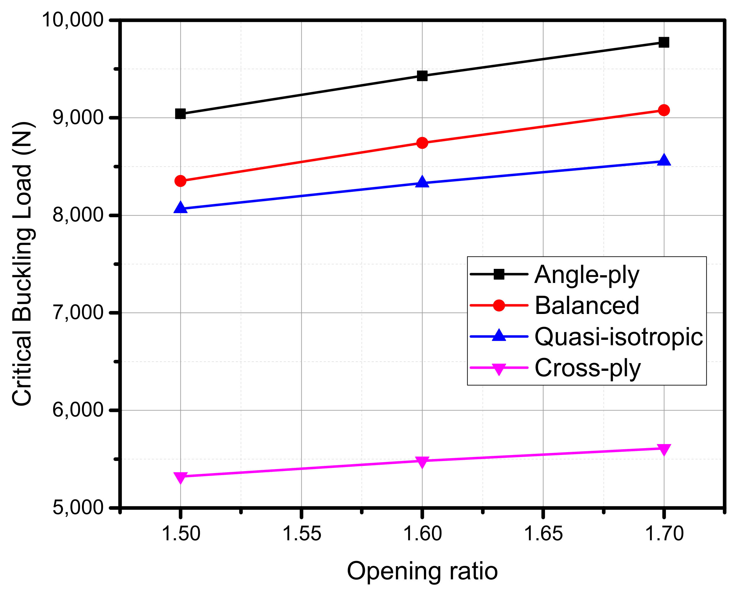
In short, ABAQUS software was used to numerically study thin-walled composite structure buckling. The critical buckling load was calculated using eigenvalue linear buckling. Four laminates were studied to see how parameters affect response and critical buckling load. Then, the results were optimized. This study used a full factorial orthogonal array first, then obtained eigenvalue buckling data for all cases to better understand the data. The obtained data were then analysed using MINITAB and Design Expert software using response surface methodologies to verify model estimation, graphs, and variable contours and levels. The W/Wo parameter had the highest F-value in all laminate types, indicating it is the most influential for one-way interaction. In quasi-isotropic, cross-ply, and balanced laminates, W/Wo and S/Wo had the highest F-value. The design of the composite thin-wall structure was influenced by these two combinations. Angle-ply can be combined in many ways. W/Wo and the cutout shape had the greatest impact on the buckling load. This study also found the best parameter combinations for different laminates in terms of critical buckling. An optimization analysis based on parameters showed that range changes affect buckling load values.
All laminates had an abrupt trend except the cross-ply laminate, which had a significant opening ratio. The opening ratio increased buckling loads, affecting response. Round laminates buckled more than hexagonal or square laminates, except for angle-ply, which had a closer margin between the circular and hexagonal shapes. The aspect ratio did not affect buckling load. Increased spacing ratio increased buckling load for quasi-isotropic and cross-ply laminates. The trend was almost flat for both angle-ply and balanced laminate, so the spacing ratio had little effect. Because both factors are steeper, the cross-ply laminate is adjustable. The QIS had a moderate effect on buckling load capacity as it increased gradually. These variables combine to determine a strut’s buckling load. A contour plot requires both parameters to work properly. These equations can be used to predict the response at any given point in the input parameters. To demonstrate this, all three equations for different shapes of angle-ply laminate cutouts were tested. The results were then compared to existing data. Finally, the response surface methodologies showed optimized results from the study’s analysis. As shown in the graph, the regression equation yielded an optimal response. It shows how the factors affect the critical buckling load and also shows the best combination for a higher critical buckling load.

Author Contributions

Conceptualization, M.N.B.K. and J.S.M.A.; methodology, M.N.B.K. and A.A.; software, M.N.B.K. and A.A.; validation, M.N.B.K., J.S.M.A. and A.A.; formal analysis, J.S.M.A., A.A. and Y.E.I.; investigation, M.N.B.K., J.S.M.A. and A.A.; resources, J.S.M.A., A.A. and Y.E.I.; data curation, J.S.M.A., A.A. and Y.E.I.; writing—original draft preparation, M.N.B.K., J.S.M.A. and A.A.; writing—review and editing, J.S.M.A., A.A. and Y.E.I.; visualization, J.S.M.A., A.A. and Y.E.I.; supervision, J.S.M.A., A.A. and Y.E.I.; project administration, J.S.M.A. and Y.E.I.; funding acquisition, Y.E.I. All authors have read and agreed to the published version of the manuscript.

Funding

This research received no external funding.

Institutional Review Board Statement

Not applicable.

Informed Consent Statement

Not applicable.

Data Availability Statement

Not applicable.

Acknowledgments

This research is supported by the Structures and Materials (S&M) Research Lab of Prince Sultan University. Furthermore, the authors acknowledge the support of Prince Sultan University for paying the article processing charges (APC) of this publication.

Conflicts of Interest

The authors declare no conflict of interest.

References

  1. Lee, J.; Nguyen, H.T.; Kim, S.-E. Buckling and post buckling of thin-walled composite columns with intermediate-stiffened open cross-section under axial compression. Int. J. Steel Struct. 2009, 9, 175–184. [Google Scholar] [CrossRef]
  2. Sastry, Y.B.; Krishna, Y.; Budarapu, P.R.; Koduganti, A. Cross Section Beams with Variable Geometry. J. Eng. Res. 2014, 3, 2498–2506. [Google Scholar]
  3. Aabid, A.; Zakuan, M.A.M.B.M.; Khan, S.A.; Ibrahim, Y.E. Structural analysis of three-dimensional wings using finite element method. Aerosp. Syst. 2022, 5, 47–63. [Google Scholar] [CrossRef]
  4. Zakuan, M.A.M.B.M.; Aabid, A.; Khan, S.A. Modelling and Structural Analysis of Three-Dimensional Wing. Int. J. Eng. Adv. Technol. 2019, 9, 6820–6828. [Google Scholar] [CrossRef]
  5. Anjum, A.; Syed, J.; Ali, M.; Zayan, J.M.; Aabid, A. Statistical Analysis of Adhesive Bond Parameters in a Single Lap Joint System. J. Mod. Mech. Eng. Technol. 2020, 7, 53–58. [Google Scholar]
  6. Rozylo, P.; Debski, H. Stability and load-carrying capacity of short composite Z-profiles under eccentric compression. Thin-Walled Struct. 2020, 157, 107019. [Google Scholar] [CrossRef]
  7. Paul, A. Buckling of Columns—Euler Theory for Elastic Buckling. 2014. Available online: https://civildigital.com/buckling-columns-euler-theory-elastic-buckling/ (accessed on 11 June 2021).
  8. Rozylo, P.; Teter, A.; Debski, H.; Wysmulski, P.; Falkowicz, K.; Pl, F. Experimental and Numerical Study of the Buckling of Composite Profiles with Open Cross Section under Axial Compression. Appl. Compos. Mater. 2017, 24, 1251–1264. [Google Scholar] [CrossRef]
  9. Rozylo, P.; Ferdynus, M.; Debski, H.; Samborski, S. Progressive Failure Analysis of Thin-Walled Composite Structures Verified Experimentally. Materials 2020, 13, 1138. [Google Scholar] [CrossRef]
  10. Khazaal, D.S.; Al-Khafaji, H.M.A.; Abdulsahib, I.A. Buckling Behavior of Aluminum Alloy Thin-Walled Beam with Holes under Compression Loading. J. Eng. 2020, 26, 137–154. [Google Scholar] [CrossRef]
  11. Kumari, E.; Saxena, D. Buckling analysis of folded structures. Mater. Today Proc. 2020, 43, 1421–1430. [Google Scholar] [CrossRef]
  12. Hoang, T.; Ádány, S. New Transverse Extension Modes for the Constrained Finite Strip Analysis of Thin-Walled Members. Thin-Walled Struct. 2021, 179, 109634. [Google Scholar] [CrossRef]
  13. Einafshar, N.; Lezgy-Nazargah, M.; Beheshti-Aval, S.B. Buckling, post-buckling and geometrically nonlinear analysis of thin-walled beams using a hypothetical layered composite cross-sectional model. Acta Mech. 2021, 232, 2733–2750. [Google Scholar] [CrossRef]
  14. Erkmen, R.E. Elastic buckling analysis of thin-walled beams including web-distortion. Thin-Walled Struct. 2022, 170, 108604. [Google Scholar] [CrossRef]
  15. Banat, D.; Mania, R.J.; Degenhardt, R. Stress state failure analysis of thin-walled GLARE composite members subjected to axial loading in the post-buckling range. Compos. Struct. 2022, 289, 115468. [Google Scholar] [CrossRef]
  16. Habtemariam, A.K.; Bianco, M.J.; Könke, C.; Zabel, V. Geometrically nonlinear formulation of Generalized Beam Theory for the analysis of thin-walled circular pipes. Thin-Walled Struct. 2022, 173, 109029. [Google Scholar] [CrossRef]
  17. Zhou, H.Q.; An, Y.; He, B.; Qi, H.N. Finite strip-Riccati transfer matrix method for buckling analysis of tree-branched cross-section thin-walled members. Adv. Mech. Eng. 2022, 14, 1–15. [Google Scholar] [CrossRef]
  18. Zhang, S. Nonlinear Finite Element Analysis of Thin-Walled Beam on Pre- and Post-Buckling Stiffness and Gauge Sensitivity Index. J. Appl. Math. Phys. 2022, 10, 1432–1442. [Google Scholar] [CrossRef]
  19. Weisz-Patrault, D.; Margerit, P.; Constantinescu, A. Residual stresses in thin walled-structures manufactured by directed energy deposition: In-situ measurements, fast thermo-mechanical simulation and buckling. Addit. Manuf. 2022, 56, 102903. [Google Scholar] [CrossRef]
  20. Zhang, G.; Zhu, H.; Wang, Q.; Zhang, X.; Ren, M.; Xue, S.; Li, G. Buckling analysis of thin-walled metal liner of cylindrical composite overwrapped pressure vessels with depressions after autofrettage processing. Sci. Eng. Compos. Mater. 2021, 28, 540–554. [Google Scholar] [CrossRef]
  21. Carrera, E.; Pagani, A.; Augello, R. Large deflection and post-buckling of thin-walled structures by finite elements with node-dependent kinematics. Acta Mech. 2021, 232, 591–617. [Google Scholar] [CrossRef]
  22. Sudhirsastry, Y.B.; Budarapu, P.R.; Madhavi, N.; Krishna, Y. Buckling analysis of thin wall stiffened composite panels. Comput. Mater. Sci. 2015, 96, 459–471. [Google Scholar] [CrossRef]
  23. Erkliǧ, A.; Yeter, E. The effects of cutouts on buckling behavior of composite plates. Sci. Eng. Compos. Mater. 2012, 19, 323–330. [Google Scholar] [CrossRef]
  24. Doan, Q.H.; Thai, D. A Numerical Study of the Effect of Component Dimensions on the Critical Buckling Load of a GFRP Composite Strut under Uniaxial Compression. Materials 2020, 13, 931. [Google Scholar] [CrossRef]
  25. Kumar, P.R.; Gupta, G.; Shamili, G.K.; Anitha, D. Linear Buckling Analysis and Comparative Study of Un-Stiffened and Stiffened Composite Plate. Mater. Today Proc. 2018, 5, 6059–6071. [Google Scholar] [CrossRef]
  26. Aabid, A.; Hrairi, M.; Ali, J.S.M. Optimization of composite patch repair for center-cracked rectangular plate using design of experiments method. Mater. Today Proc. 2020, 27, 1713–1719. [Google Scholar] [CrossRef]
  27. Aabid, A.; Khan, S.A. Investigation of High-Speed Flow Control from CD Nozzle Using Design of Experiments and CFD Methods. Arab. J. Sci. Eng. 2021, 46, 2201–2230. [Google Scholar] [CrossRef]
  28. Al-khalifah, T.; Aabid, A.; Khan, S.A.; Azami, M.H.B.; Baig, M. Response surface analysis of the nozzle flow parameters at supersonic flow through microjets. Aust. J. Mech. Eng. 2021, 13, 1–15. [Google Scholar] [CrossRef]
  29. Aabid, A.; Khan, S.A.; Afzal, A.; Baig, M. Investigation of tiny jet locations effect in a sudden expansion duct for high-speed flows control using experimental and optimization methods. Meccanica 2022, 57, 17–42. [Google Scholar] [CrossRef]
  30. Kumari, M.; Gupta, S.K. Response surface methodological (RSM) approach for optimizing the removal of trihalomethanes (tHMs) and its precursor’s by surfactant modified magnetic nanoadsorbents (sMnp)-An endeavor to diminish probable cancer risk. Sci. Rep. 2019, 9, 1–11. [Google Scholar] [CrossRef] [Green Version]
Figure 2. A model description with its dimension.
Aerospace 09 00541 g002
Figure 3. The illustration of the model setup.
Aerospace 09 00541 g003
Figure 4. The model boundary and loading conditions at the top (a) and bottom (b) end.
Aerospace 09 00541 g004
Figure 5. The illustration of the local coordinate system for a laminate.
Aerospace 09 00541 g005
Figure 6. Initialized definition of fibre orientation on flanges (a) and web (b).
Aerospace 09 00541 g006
Figure 7. The lamination stack modelled on each section for quasi-isotropic laminate.
Aerospace 09 00541 g007
Figure 8. The description of the opening and spacing ratio.
Aerospace 09 00541 g008
Figure 9. Step required to conduct RSM.
Aerospace 09 00541 g009
Figure 10. The convergence test result.
Aerospace 09 00541 g010
Figure 11. Displacement of angle-ply laminate for all shapes.
Aerospace 09 00541 g011
Figure 12. Displacement of balanced laminate for all shapes.
Aerospace 09 00541 g012
Figure 13. Displacement of quasi-isotropic laminate for all shapes.
Aerospace 09 00541 g013
Figure 14. Displacement of cross-ply laminate for all shapes.
Aerospace 09 00541 g014
Figure 15. Effect of hole shapes on critical buckling load for different laminates.
Aerospace 09 00541 g015
Figure 16. Effect of opening ratio on critical buckling load for different laminates.
Aerospace 09 00541 g016
Figure 17. Effect of spacing ratio on critical buckling load for different laminates.
Aerospace 09 00541 g017
Figure 18. Nonlinear analysis for critical buckling load for the quasi-isotropic model without holes.
Aerospace 09 00541 g018
Figure 19. Nonlinear analysis for critical buckling load for the angle-ply model without holes.
Aerospace 09 00541 g019
Figure 20. Nonlinear analysis for critical buckling load for the balanced model without holes.
Aerospace 09 00541 g020
Figure 21. Nonlinear analysis for critical buckling load for the cross-ply model without holes.
Aerospace 09 00541 g021
Figure 22. All laminate types’ main effects plot for fitted means: (a) angle-ply, (b) balanced, (c) quasi-isotropic, and (d) cross-ply.
Aerospace 09 00541 g022aAerospace 09 00541 g022b
Figure 23. Contour plot for angle-ply laminate: (a) circular, (b) hexagon, and (c) square.
Aerospace 09 00541 g023
Figure 24. Contour plot for balance laminate: (a) circular, (b) hexagon, and (c) square.
Aerospace 09 00541 g024
Figure 25. Contour plot for quasi-isotropic laminates: (a) circular, (b) hexagon, and (c) square.
Aerospace 09 00541 g025
Figure 26. Contour plot for cross-ply laminate: (a) circular, (b) hexagon, and (c) square.
Aerospace 09 00541 g026
Figure 27. Comparison of FEA and regression model.
Aerospace 09 00541 g027
Table 1. GFRP properties used for simulation.
E1 (Mpa)E2 (Mpa)υG12 (Mpa)G13 (Mpa)G23 (Mpa)
38,00081000.27200020002000
Table 2. The parameters and levels.
ParameterLevels
123
W/Wo1.51.61.7
D/Wo1.31.41.5
ShapesCircularSquareHexagonal
Table 3. FEM results were obtained from simulation for different types of laminate.
Run OrderW/WoS/WoSHAPECritical Buckling Load (N)
Angle-PlyBalancedQuasi-IsotropicCross-Ply
11.71.5CIRCULAR9773.79077.585545611.1
2HEXAGON9464.48765.28271.35387.8
3SQUARE9108.18411.47963.35146.9
41.61.5CIRCULAR9430.487428330.15483
5HEXAGON910984118024.75233.9
6SQUARE8644.68064.37727.54998.8
71.51.5CIRCULAR9040.98351.78066.85323
8HEXAGON8716.28011.37746.65055.8
9SQUARE81297600.47471.94844.5
101.71.4CIRCULAR9798.99084.68495.75507.2
11HEXAGON94758761.38201.65280
12SQUARE9107.28397.87879.95031
131.61.4CIRCULAR9438.78738.68253.35366.6
14HEXAGON910083937937.15118.1
15SQUARE8639.18028.97618.44866
161.51.4CIRCULAR90298332.679745200.1
17HEXAGON8680.1797076374927.7
18SQUARE8049.57559.57335.34688.2
191.71.3CIRCULAR9844.59107.384525410.4
20HEXAGON9505.98774.681455172.5
21SQUARE9131.38406.47822.24930.9
221.61.3CIRCULAR9468.98752.681905253.5
23HEXAGON9105.683877854.54993.4
24SQUARE86538011.67530.44744.7
251.51.3CIRCULAR9035.38329.77890.65076
26HEXAGON8648.27940.57528.64789.8
27SQUARE7988.47521.37213.74543.7
Table 5. Different element sizes test.
Element SizeCritical Buckling Load (N)Number of ElementPercentage Error (%)
111,23240,0000.230947
211,25510,0000.026648
311,31343990.488541
411,36525200.950435
511,42316001.465624
Table 6. Quasi-isotropic ANOVA.
SourceDFAdj SSAdj MSF-Valuep-Value
Model113,257,334296,12111,702.660.000
  Linear43,244,740811,18532,057.890.000
      W/Wo1134,50731,345,07353,157.070.000
      S/Wo1129,914129,9145134.180.000
      SHAPE2176,9753884,87634,970.160.000
  Square2173886934.350.000
      W/Wo*W/Wo11478147858.410.000
      S/Wo*S/Wo126026010.290.006
  2-Way Interaction510,856217185.800.000
      W/Wo*S/Wo166746674263.760.000
      W/Wo*SHAPE2153276630.280.000
      S/Wo*SHAPE22649132452.340.000
Error1538025
Total26
Table 7. Angle-ply ANOVA.
SourceDFAdj SSAdj MSF-Valuep-Value
Model116,640,780603,7072127.510.000
  Linear46,542,3701,635,5925763.960.000
      W/Wo13,460,5543,460,55412,195.280.000
      S/Wo169690.240.629
      SHAPE23,081,7471,540,8735430.170.000
  Square28385419214.770.000
      W/Wo*W/Wo17896789627.830.000
      S/Wo*S/Wo14884881.720.209
2-Way Interaction590,02518,00563.450.000
      W/Wo*S/Wo110,19110,19135.910.000
      W/Wo*SHAPE275,98137,991133.880.000
      S/Wo*SHAPE2385319266.790.008
Error154256284
Total266,645,036
Table 8. Cross-ply laminate ANOVA.
SourceDAdj SSAdj MSF-Valuep-Value
Model111,870,705170,0646065.490.000
  Linear41,864,835466,20916,627.760.000
      W/Wo1509,713509,71318,179.390.000
      S/Wo1261,581261,5819329.540.000
      SHAPE21,093,541546,77019,501.060.000
  Square268134012.140.001
      W/Wo*W/Wo166466423.690.000
      S/Wo*S/Wo117170.590.454
2-Way Interaction55189103837.010.000
      W/Wo*S/Wo12754275498.230.000
      W/Wo*SHAPE2170285130.360.000
      S/Wo*SHAPE273236613.060.001
Error1542128
Total26
Table 9. Balanced laminate ANOVA.
SourceDFAdj SSAdj MSF-Valuep-Value
Model115,237,892476,1727286.760.000
  Linear45,217,4841,304,37119,960.510.000
      W/Wo12,855,3332,855,33343,694.550.000
      S/Wo12307230735.310.000
      SHAPE22,359,8431,179,92218,056.090.000
  Square28271413663.280.000
      W/Wo*W/Wo179427942121.540.000
      S/Wo*S/Wo13293295.030.040
  2-Way Interaction512,137242737.150.000
      W/Wo*S/Wo13540354054.170.000
      W/Wo*SHAPE26514325749.840.000
      S/Wo*SHAPE22084104215.940.000
Error1598065
Total265,238,872
Publisher’s Note: MDPI stays neutral with regard to jurisdictional claims in published maps and institutional affiliations.

