Article

Design and SAR Analysis of a Dual Band Wearable Antenna for WLAN Applications

1
Communication and Wave Propagation Laboratory, Department of Information and Communication Engineering, Chosun University, Gwangju 61452, Korea
2
National Institute of Scientific Research (INRS), University of Quebec, Montreal, QC H5A 1C6, Canada
3
Department of Telecommunication Engineering, University of Engineering and Technology, Mardan 23200, Pakistan
*
Author to whom correspondence should be addressed.
Appl. Sci. 2022, 12(18), 9218; https://doi.org/10.3390/app12189218
Submission received: 28 July 2022 / Revised: 9 September 2022 / Accepted: 12 September 2022 / Published: 14 September 2022
(This article belongs to the Special Issue Data Analysis and Artificial Intelligence for IoT)

Abstract

:
This paper presents the design of three types of dual band (2.5 & 5.2 GHz) wearable microstrip patch antennas. The first one is based on a conventional ground plane, whereas the other two antennas are based on two different types of two-dimensional electromagnetic band gap (EBG) structures. The design of these two different dual-band EBG structures using wearable substrates incorporates several factors in order to improve the performance of the proposed conventional ground plane (dual band) wearable antenna. The second EBG with plus-shaped slots is about 22.7% more compact in size relative to the designed mushroom-like EBG. Subsequently, we have demonstrated that the mushroom-like EBG and the EBG with plus-shaped slots improve the bandwidth by 5.2 MHz and 7.9 MHz at lower resonance frequencies and by 33.6 MHz and 16.7 MHz at higher resonance frequencies, respectively. Furthermore, improvements in gain of 4.33% and 16.5% at a frequency of 2.5 GHz and improvements in gain of 30.43% and 4.57% at 5.2 GHz have been achieved by using the mushroom-like EBG and EBG with plus-shaped slots, respectively. The operation of the conventional ground plane antenna is investigated under different bending conditions, such as wrapped around different rounded body parts. The proposed conventional ground plane antenna is placed over a three-layered (flat body phantom (chest)) and four-layered (rounded body parts) tissue models, and a thorough SAR analysis has been performed. It is concluded that the proposed antenna reduces SAR effects (<2 W/kg) on the human body, thereby making it useful for numerous critical wearable applications.

1. Introduction

Wearable systems provide an extension in the classical concept of wearable apparel, which is used for the protection of the body from environmental effects. These systems have introduced new services and need to be completely integrable into the wearable apparel without affecting its comfortability and wearability. A wearable antenna is the main component in a wearable system and serves as a crucial bridge between the external electronic devices and the on-body electronic circuitry [1]. These antenna-based systems are being utilized for security, rescue, sports, entertainment and many other applications [2]. Therefore, they are expected to exhibit resilience to the harsh environment and have a small size. Antenna miniaturization is often achieved by the reduction of the ground plane [3]. However, a reduced ground plane results in spurious currents flowing in the ground plane, which can affect the radiation characteristics of that antenna. Some other miniaturization techniques are also used for antenna size reduction, such as loading lumped components, creating slots [4] and bends, and using short circuits and spiral-shaped radiators [5], among many other techniques. However, patch antennas, because of their peculiar properties, are always favorable for wearable applications [6]. The radiation pattern of a patch antenna is perpendicular to the antenna plane, which is why, in terms of low specific absorption rate (SAR), patch antennas are the best candidates for these applications. Furthermore, the full ground plane, which is a component of a patch antenna, is beneficial in preventing the wearer’s body from unwanted radiation [7], and this further helps reduce the SAR value.
Whenever an antenna is installed on a wearer’s body, its side and back radiation lobes penetrate into the user’s body, thereby being absorbed. Absorption of these lobes or waves produce hot spots on the human body, and destruction of tissues may occur [8,9]. The specific absorption rate (SAR) defined in Equation (1) is the value formulated to calculate the absorption of electromagnetic waves by human tissue:
SAR = σ E 2 ρ ( W / kg )
where E is the root-mean-square electric field induced in the tissue (V/m), ρ is the tissue density ( kg / m 3 ) and σ is the tissue electrical conductivity (s/m), and its value dictates quantity of maximum exposure to the electromagnetic fields. Beginning in the year 1990, the SAR value of the interaction of an antenna with the human body received tremendous attention [10,11] because of the huge increase in wireless body area network (WBAN) applications. The SAR value should not exceed the recommended exposure thresholds, and it should remain within a predefined SARlimit. Therefore, different techniques [12,13] were used by researchers to bring the SAR value into the desired limit. The electromagnetic band-gap (EBG) acts as a shield and reduces the SAR value [14,15] by efficiently radiating the side and back radiation lobes in the forward direction to protect the human body. It has been shown in some publications [16] that a ferrite sheet also acts as a protective shield and provides stability in terms of resonant frequencies, irrespective of the antenna position on the body. It therefore can be used as an alternative to EBG for SAR reduction.
In most cases, the antenna performance is degraded when it is in proximity to the wearer’s body or when it acquires a bend [17]. This degradation in performance is due to the permittivity and conductivity of human tissues. Besides the effects due to conductivity and permittivity of tissues, bending may produce a change in the effective electrical length of antenna or mismatch the impedance. Consequently, a shift in the resonance frequency or decrease/increase in the return loss may occur [18]. Therefore, an evaluation of the different parameters of a wearable antenna on a body and in different bending conditions is required to be explored. High impedance surfaces or EBG structures are used to minimize this degradation in performance [14]. EBG structures are artificial materials used as a ground plane for antennas. These structures enhance the overall performance of an antenna by providing in-phase reflection and surface wave suppression [19,20,21,22]. Another aspect of EBG can be found in array antennas. Mutual coupling is a severe problem in array antennas or multiple antenna systems [23,24]. This problem of mutual coupling between multiple antenna elements can be overcome by utilizing EBG [25,26]. Instead of EBG, the same objective can be achieved by using defected ground structures (DGS) [27]. However, in some cases, as in [28], the gain of the array antenna may be significantly reduced by using DGS. Therefore, EBG is a better choice compared to DGS.
In most of the work in literature, only flat antenna conditions are usually considered for the antenna performance [29] and SAR measurements [30,31]. However, due to the flexibility of wearable antennas, it is not possible for these antennas to maintain their flat conditions all the time on a wearer’s body. Moreover, the SAR value is a function of the bending radius of a specified body organ [32]; the smaller the bending radius, the worse the SAR value. Furthermore, crumpling and bending an antenna may reduce its performance, as reported in [33]. Therefore, in this paper, we provide a comprehensive SAR analysis as well as the impact of other antenna parameters on both flat and bending conditions. In addition, we consider antenna bending conditions based on various wearable antenna radii sizes specified on the basis of the corresponding human arms and legs on which they are wrapped.
In this work, a very compact size dual band wearable microstrip patch antenna operating at 2.5 and 5.196 GHz is designed. In order to improve the performance of antenna in terms of directivity, gain and bandwidth, two types of EBG ground planes were designed for the proposed conventional antenna. The antenna is low profile and conformable and is composed of a textile material called polyethylene foam, having a relative permittivity of 1.05. The proposed antenna is bent around human legs and arms of different radii, and its operation is studied under various bent conditions. For the on-body simulation, two types of body phantoms are modeled. The first one is a flat body phantom (used for the chest) consisting of three layers, whereas the second one is a cylindrical body phantom (used for the arms and legs) consisting of four different layers. The proposed antenna is placed on the flat body phantom as well as bent around arms (of different radii) and legs, and its SAR analysis is carried out. We use CST MWS software for all the simulations and analysis in this work.
The rest of the paper is organized into the following sections. Section 2 provides our design methodology using various approaches. In Section 3, we present the human phantom modeling approach and describe our simulation results based on off-body and on-body analyses. Furthermore, we thoroughly discuss the impact of various antenna positions. In Section 4, we conclude the paper and discuss some open questions.

2. Design Methodology

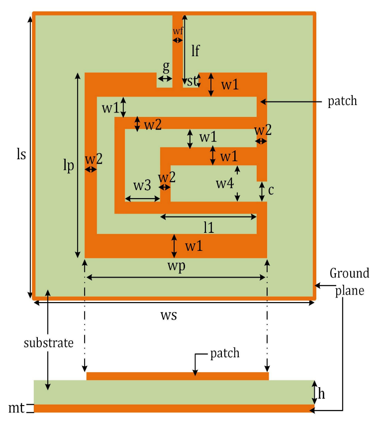
2.1. Conventional Approach

All the designs and simulations in this project were carried out in CST MWS software with a frequency range of 2 to 5.5 GHz. The geometrical model of the proposed dual band wearable patch antenna is shown in Figure 1. The 3 mm thicker substrate having a compact size of 68 mm × 73 mm was made of polyethylene foam with a relative permittivity of 1.05 [34]. The overall size of the radiating patch was 44.75 mm × 47 mm. A 50 Ω microstrip feed line was used in the design of the proposed dual band textile antenna. The dimensions of the proposed dual band textile antenna were obtained by using the theory of transmission lines [35].
Table 1 presents the optimized values of the parameters mentioned in Figure 1.

2.2. Metamaterial Based Approach

Metamaterials are artificially-designed materials that are used as a ground plane to enhance the performance of an antenna. These materials offer suppression of surface waves at intended frequency bands, thereby offering improvements in efficiency, gain, directivity and other parameters of an antenna. The design of two different unit cells of the two different EBG structures to be employed as a ground plane for the designed dual band wearable antenna is outlined in the section below.

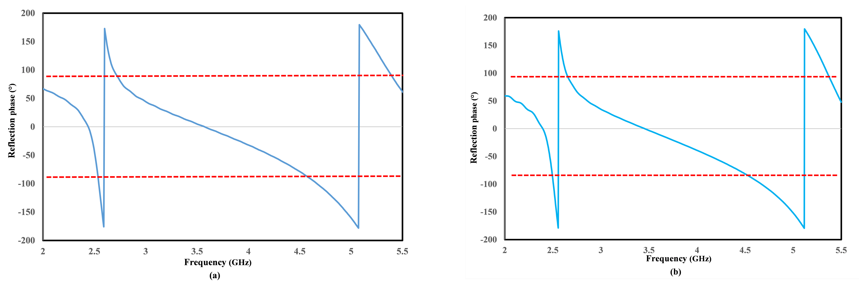
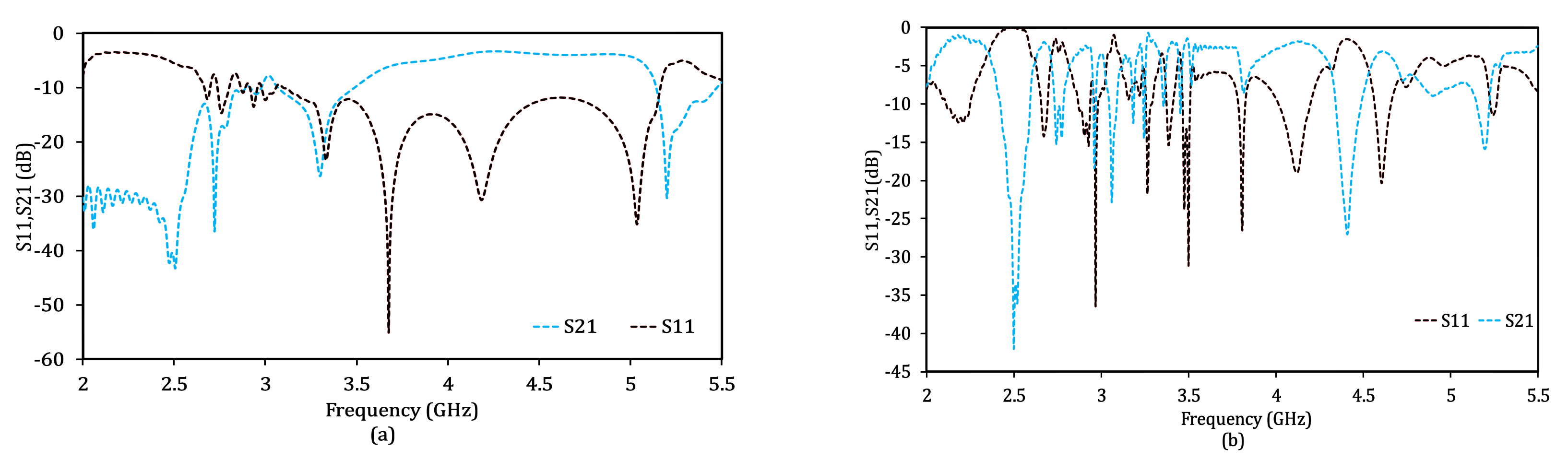
2.2.1. Dual Band EBG Unit Cells

This section summarizes the design and analysis of two different unit cells of the two different EBG structures for the desired frequency bands (2.5 GHz and 5.196 GHz). Polyethylene with a thickness of 3 mm was utilized as a substrate material in the design of these two EBG structures. For the unit cell, the resonant frequency depends on the effective capacitance (C) and inductance (L) of the unit cell, i.e.,
f r = 1 2 π L C
C = w ϵ o ( 1 + ϵ r ) π cosh 1 a g
L = μ o h
where μ 0 and ϵ 0 are the free space permeability and permittivity, respectively. Figure 2 presents the design of the two dual band EBG unit cells. The first one is the conventional mushroom-like EBG unit cell. It is a square shape with overall dimensions of 32.5 mm × 32.5 mm. The radius of the via is 1.5 mm. The second unit cell is different from the conventional mushroom-like EBG unit cell. A plus-shaped slot is created in the unit cell. The creation of slots increases the capacitance and thus makes the proposed unit cell more compact in size as compared to the conventional mushroom-like EBG unit cell [36]. The second EBG unit cell with a plus-shaped slot has a total size of 26.5 mm × 26.5 mm. The second EBG unit cell is about 18.46% more compact in size as compared to the conventional mushroom-like EBG unit cell. The width and length of the plus-shaped slot in the second EBG unit cell are 3 mm and 13 mm, respectively.
The in-phase reflection of the proposed dual-band EBG unit cells are shown in Figure 3. It is observed that in the case of each EBG unit cell, the in-phase response is shown on the desired resonances (2.5 GHz and 5.2 GHz).
Table 2 presents the values of the parameters of the unit cells given in Figure 2.
Table 2 shows that the EBG unit cell with the plus-shaped slot is more compact than the mushroom-like EBG unit cell.

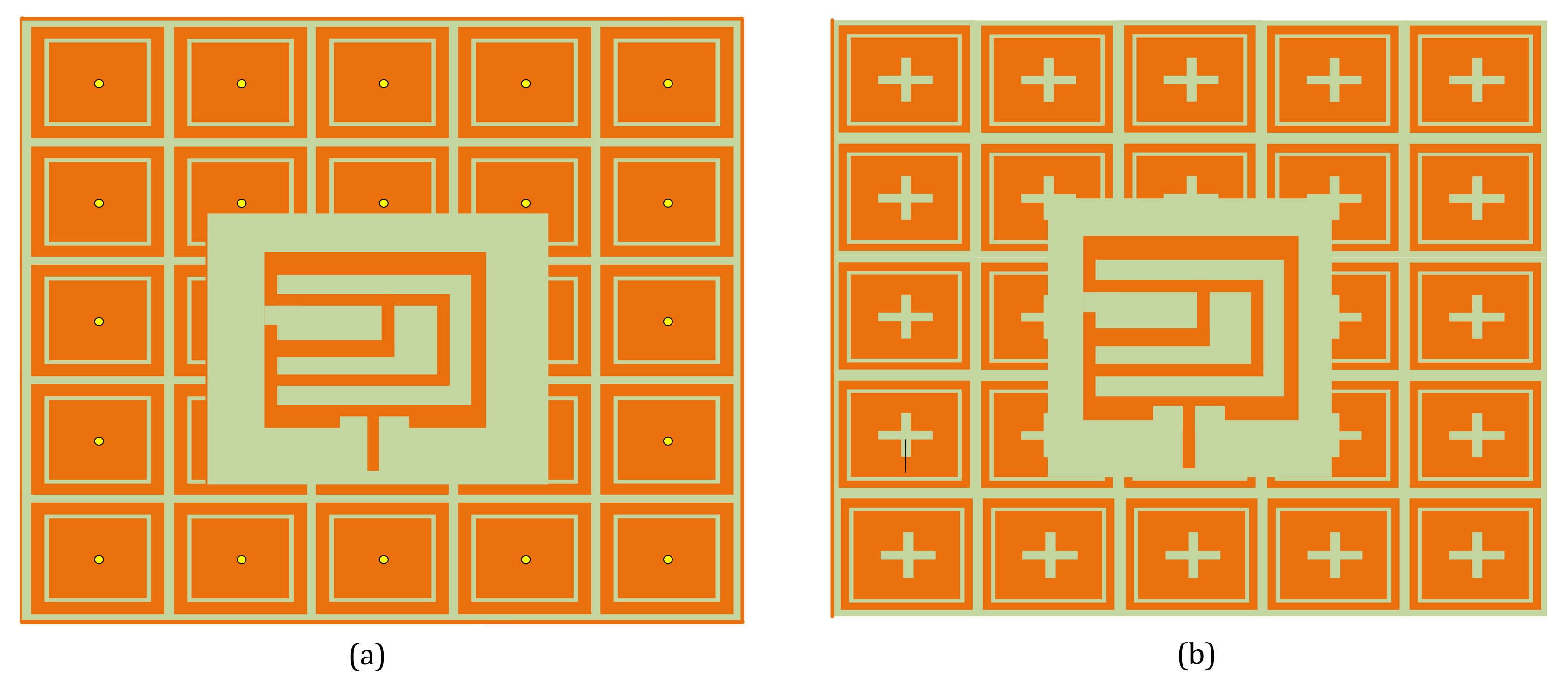
2.2.2. Electromagnetic Band-Gap Array

Surface wave suppression is one of the most important properties of EBG structures. Suppression of surface waves improves the gain, directivity and other parameters of the antenna, while it minimizes side and back lobes [37]. The scattering parameters of the two EBG surfaces are achieved by the use of two port transmission line techniques, as depicted in Figure 4. Out of the two ports, the one to the left side is supposed as the source of excitation, and the other to the right side is supposed as a matched load. The mushroom-like EBG array has a total size of 176.5 mm × 176.5 mm, while the second EBG array with plus-shaped slots is 136 mm × 136 mm.
The reflection and transmission coefficients of the two EBG structures are depicted in Figure 5. It shows that in the case of each EBG, the S21 is lower than −15 dB at both frequencies (2.5 GHz and 5.196 GHz). Therefore, both EBG structures have the ability to suppress surface waves in the desired frequency bands (2.5 GHz and 5.196 GHz). However, the second EBG structure with plus-shaped slots is about 22.94% more compact than the conventional mushroom-like EBG array.

2.3. EBG-Based Antenna

The proposed dual band textile antenna was placed over two different 5 × 5 EBG ground planes as shown in Figure 6. In the case of the mushroom-like EBG’s ground plane, the overall dimension of the antenna was 176.5 mm × 176.5 mm, whereas, in the case of the EBG ground plane with plus-shaped slots was 136 mm × 136 mm.
This means that the antenna with second ground plane is about 22.94% more compact in size than the mushroom-like EBG-based antenna.

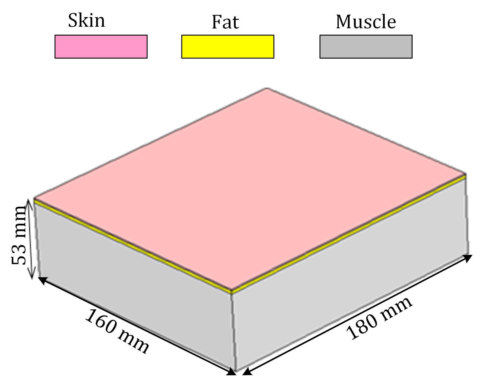
2.4. Human Phantom Modeling

For the on-body analysis of the proposed dual band wearable antenna, two body parts were modeled in CST MWS. The first one was a flat homogeneous phantom (chest) with three layers used to model muscle, fat and skin. Similarly, the second one was a heterogeneous cylindrical phantom with four layers to model bone, muscle, fat and skin. The flat body phantom had overall dimensions of 160 mm × 180 mm ×53 mm, as shown in Figure 7. The thickness of the muscle layer was 50 mm, while the thickness of the fat layer was 2 mm and the skin was 1 mm.
In the second case, three heterogeneous cylindrical models of body parts were designed, and the proposed dual band antenna was bent over them, as shown in Figure 8. The first one was a leg having a total radius of 70 mm. The second one was a healthy arm having a 60 mm radius, and the third one, which models the worst condition among all, was a child’s arm having a 40 mm radius.
The average typical electromagnetic properties for the human tissues (bone, muscle, fat and skin) at 2.5 GHz and 5.2 GHz are taken from [38] and are given in Table 3.

3. Results

3.1. Off-Body Analysis

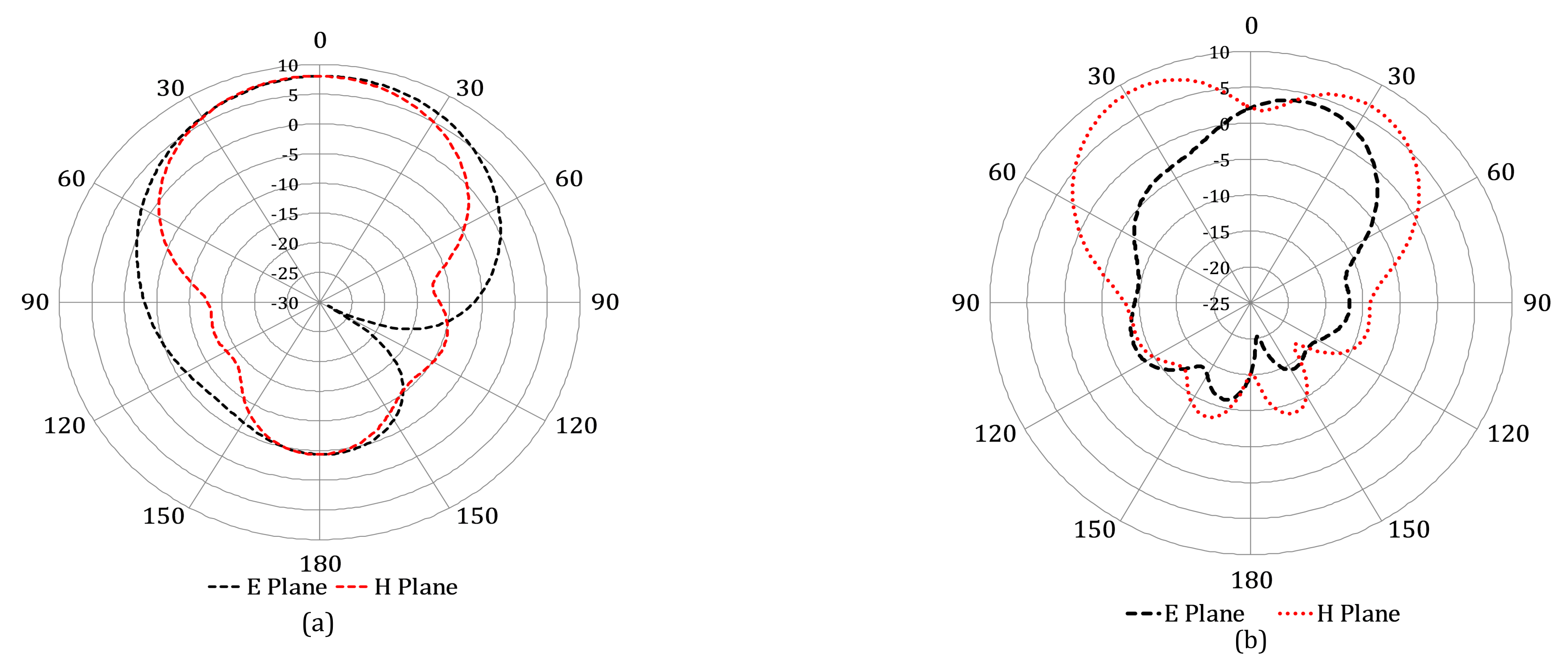
3.1.1. Conventional Antenna

The proposed dual-band wearable antenna operating at 2.5 GHz and 5.2 GHz was designed in CST MWS software with a frequency range of 2 to 5.5 GHz, as shown in Figure 1. Figure 9 shows the return loss of the designed dual band antenna. The resonance frequencies were 2.5 and 5.2 GHz with an input impedance bandwidth of 23.8 and 60.4 MHz, respectively. The proposed antenna had a return loss of −24.975 and −28.234 at 2.5 and 5.5 GHz, respectively.
Figure 10 shows that the proposed antenna is very precisely matched at both resonance frequencies with a voltage standing wave ratio (VSWR < 1.119).
The directivity and gain patterns of the designed conventional dual band antenna at 2.5 and 5.2 GHz are shown in Figure 11 and Figure 12, respectively. The maximum directivities at 2.5 and 5.2 GHz are 8.39 and 9.01 dB, respectively. The 3dB angular widths at 2.5 and 5.2 GHz are 83.4 and 76.9 degrees, respectively. The maximum gains at 2.5 and 5.2 GHz are 8.08 and 8.74 dBi, respectively. A small amount of disturbance is observed in the patterns at the higher resonance frequency. The second reason for this disturbance is the compact size of the proposed antenna. The miniaturization of an antenna is always a matter of compromise between antenna radiation characteristics and its size. Therefore, various slots have been created in the designed dual band antenna to bring it to a very compact size of 68 × 73 mm 2 .
The distribution of surface currents in the conventional wearable antenna at 2.5 and 5.2 GHz is shown in Figure 13, which clearly shows the resonant lengths.

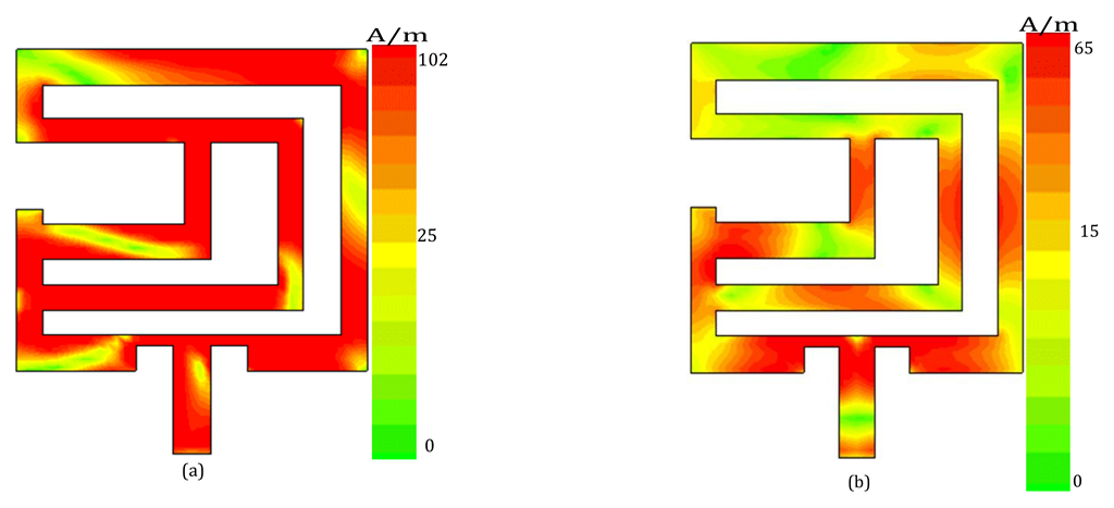
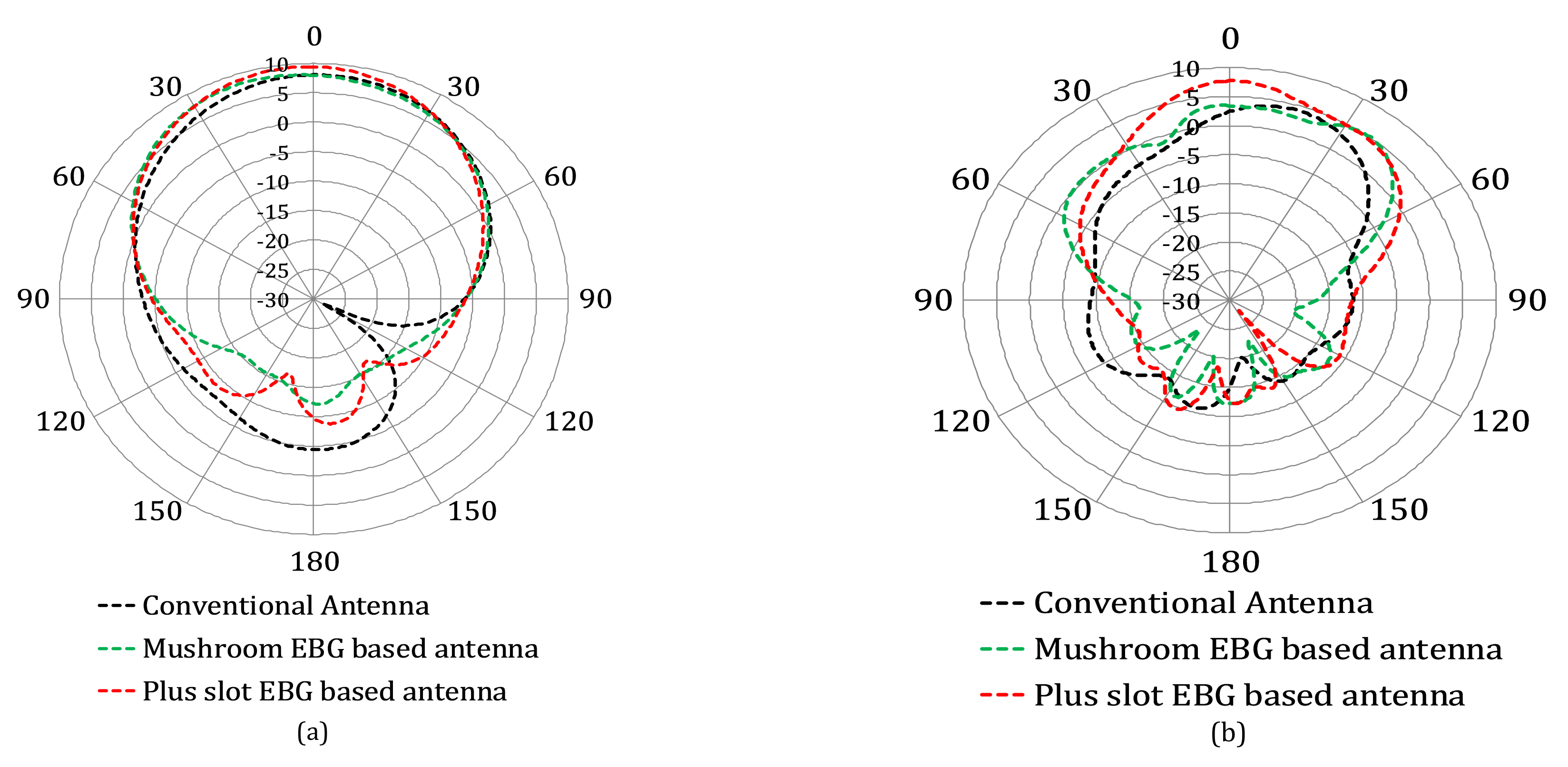
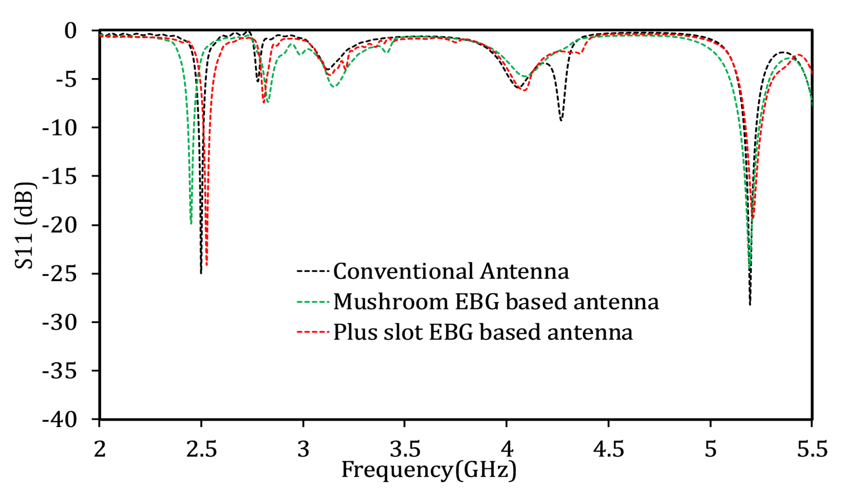
3.1.2. Metamaterial-Based Antenna

To improve the performance of the designed conventional dual band antenna, two different types of EBG ground planes have been designed in CST software, as shown in Figure 3. Subsequently, these EBG surfaces have been employed as a ground plane for the proposed dual band wearable antenna, as shown in Figure 6, and an analysis on the basis of a performance comparison is presented below.
Figure 14 shows the comparison of the return loss of the conventional dual band wearable antenna with that of the two EBG-based ground plane antennas.
With the help of the mushroom-like EBG ground plane, a 5.2 and 33.6 MHz improvement in bandwidth has been achieved for the lower and upper frequency bands, respectively. By using the EBG with plus-shaped slots as the ground plane for the proposed antenna, a 7.9 and 16.7 MHz improvement has been achieved in the bandwidth for the 2.5 and 5.2 GHz bands, respectively. A small amount of reduction in return loss has been observed for both EBG ground planes. Moreover, for the lower frequency band, a certain amount of shift to the left side for the mushroom-like EBG ground plane and to the right side for the EBG with plus-shaped slots has been observed. This shift in the resonance frequencies has also been observed in [36,39] when the antenna is employed on a metamaterial-based ground plane.
The directivity and gain patterns without and with EBG ground planes at 2.5 and 5.2 GHz are shown in Figure 15 and Figure 16. An increase of approximately 1.8% and 28.7% in directivity for the lower and upper frequency bands, respectively, has been achieved by the help of the mushroom-like EBG ground plane. By using the EBG with plus-shaped slots, a 15.13% improvement in directivity for the lower frequency band and a 3.55% improvement in that for the higher frequency band have been observed. Similarly, the mushroom-like EBG and EBG with plus-shaped slots show 4.33% and 16.70% improvements in gain for the lower frequency band, respectively, and 30.43% and 4.57% increases in gain for the upper frequency band, respectively. Furthermore, a reduction in side and back lobes is clearly observed in the case of both EBG ground planes. Apart from the directivity and gain, the radiation and total efficiency increase sufficiently for both the resonance bands in the case of both EBG ground planes.
Table 4 summarizes the performance comparison of the conventional dual band antenna without and with EBG ground planes.

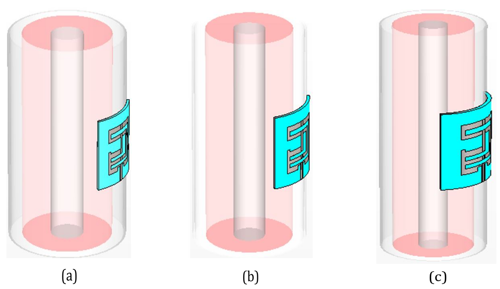
3.1.3. Conventional Antenna in Different Free Space Bending Conditions

The primary utilization of wearable antennas is their usage in on-body health or sports equipment or in security gadgets. All these applications are wearable in nature, and hence, it is impossible to maintain a regular flat antenna condition all the time when these gadgets are worn on the wearer’s body. Consequently, the antenna bending phenomenon occurs during its regular operation, which can adversely affect the performance of the corresponding system of gadget installed with the antenna. For this reason, a thorough analysis of a wearable antenna in various bending conditions can result in improved designs and better results in future wearable systems. Therefore, we used the conventional dual band wearable antenna as given in Figure 1 and bent it around different body parts as shown in Figure 8. In this work, we analyzed our proposed conventional antenna by evaluating its various bending conditions on the basis of its return loss and radiation characteristics. We describe our analysis of various results of the antenna system below.
Figure 17 illustrates the effects on the return loss of the conventional dual band wearable antenna due to bending around a leg with a radius of 70 mm, a healthy arm with a radius of 60 mm, and the worst case, which is a child’s arm with a radius of 40 mm. It is worth noticing that irrespective of the bending radii, the return loss result of the antenna is stable when bent on these body parts. The return loss is improved by about 15.16 dB at 2.5 GHz for bending around the radius of a child’s arm (40 mm). Similarly it is improved by about 5.68 dB at 5.2 GHz for bending around a leg of radius 70 mm. It is clear from Figure 17 that the bending radii have no prominent effects on the return loss of the proposed dual band wearable antenna.
Figure 18 and Figure 19 portray the effects on the directivity and gain patterns, respectively, at the desired resonance frequencies when the proposed conventional dual band patch antenna is bent around body parts of different radii. It is worth mentioning that a very small amount of reduction in directivity and gain for the lower frequency band is observed as the bending radius decreases. However, there is no prominent effect of the bending on the radiation characteristics of the conventional patch antenna, and its overall performance remains stable in terms of return loss and radiation patterns.

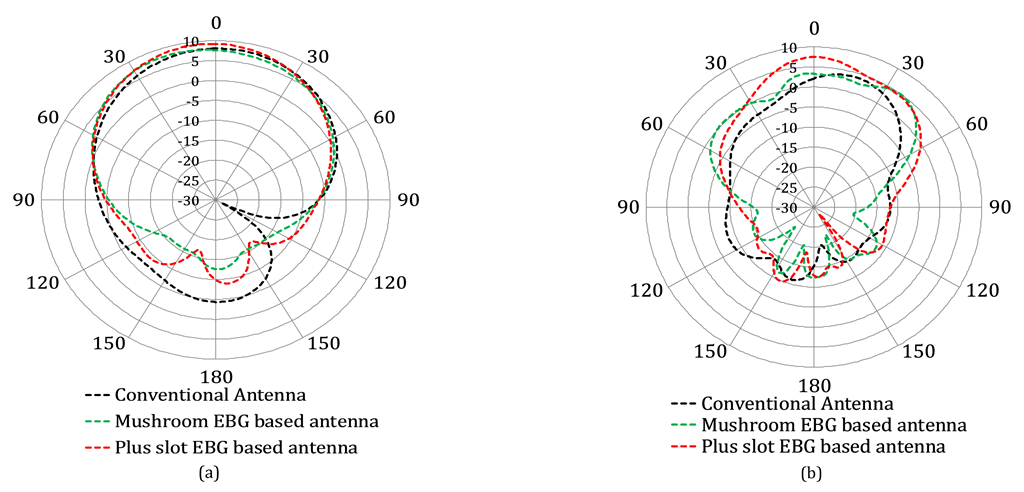
3.2. On-Body Analysis
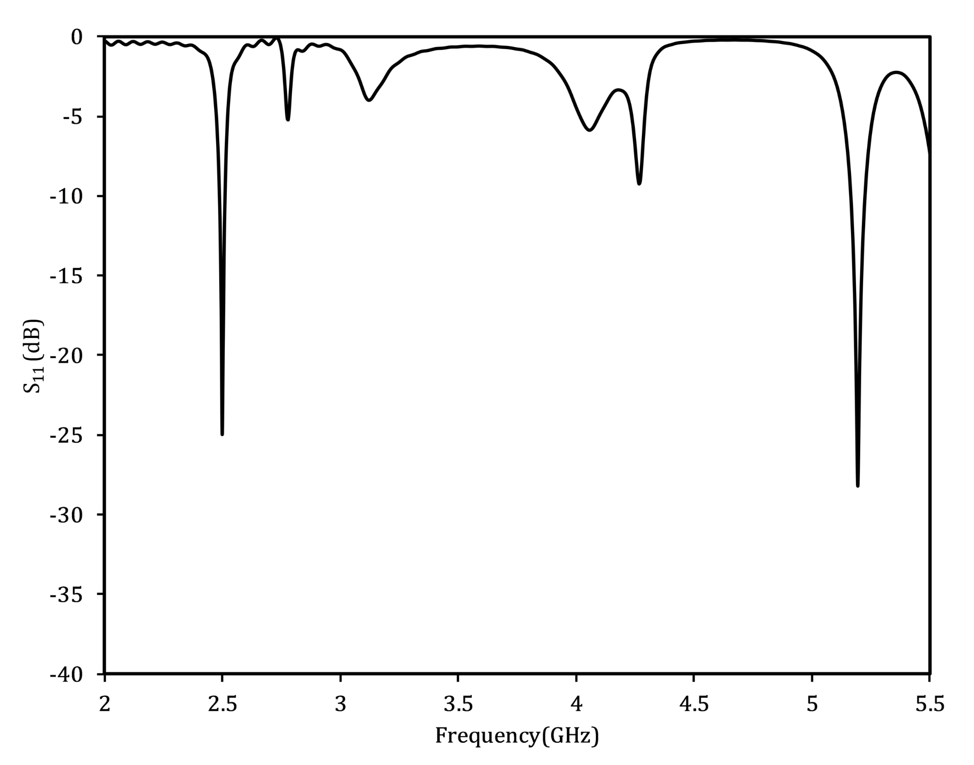
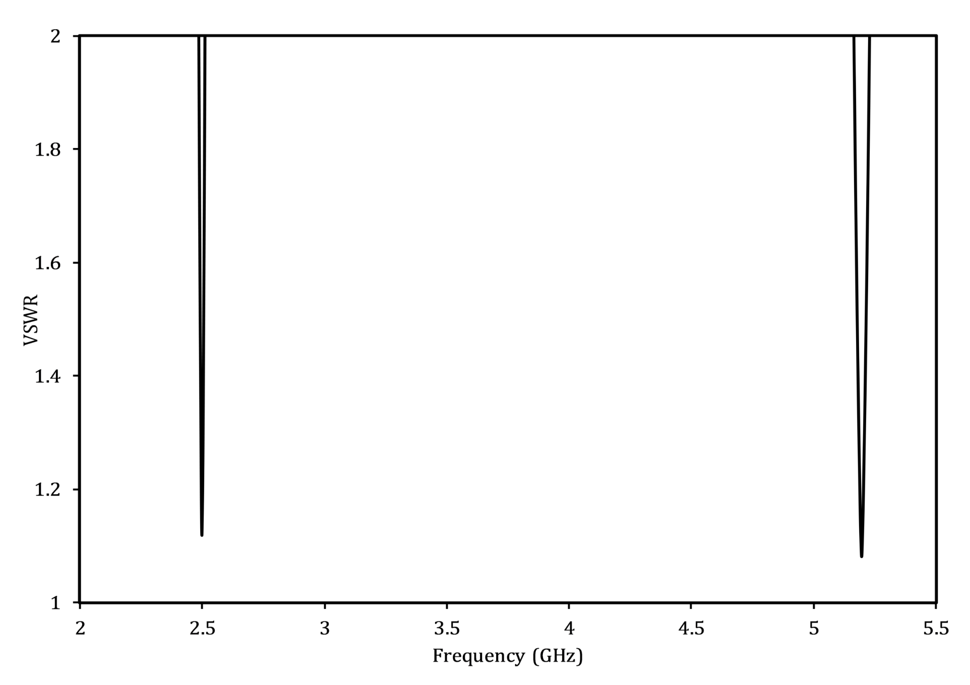
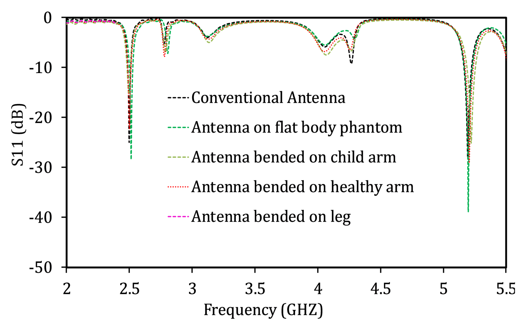
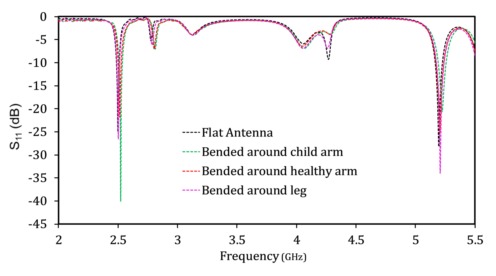
In this section, the proposed dual band conventional antenna is placed over human body and an analysis is conducted on the basis of the return loss, radiation patterns and specific absorption rate (SAR) values.

3.2.1. Return Loss

Figure 20 presents the return loss comparison of the proposed conventional antenna without a body, with the flat body phantom, and bent around rounded body parts (leg and arms). Both resonance frequencies increase as the antenna is placed over the body parts. This is due to the permittivity and conductivity of human tissues. Moreover, the shift in the resonance frequencies towards the right side increases as the bending radius decreases. This is due to the fact that the effective resonant length of the antenna depends on the bending radii. The smaller the bending radii, the greater the reduction in the effective length of the antenna, and therefore, shifting of the resonant frequency towards higher frequencies is observed [40]. However, in general, it can be observed that the proposed antenna is tuned all the time, irrespective of the different environmental conditions.

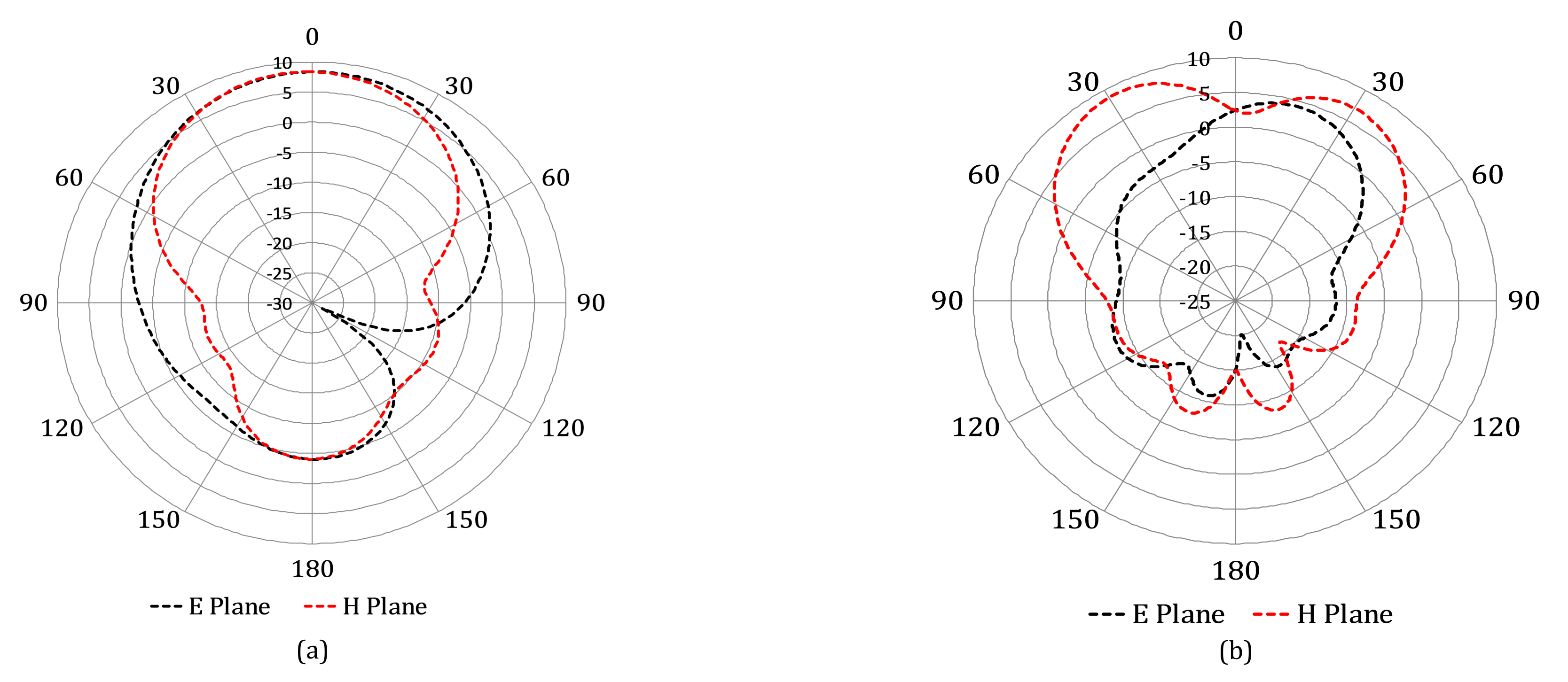
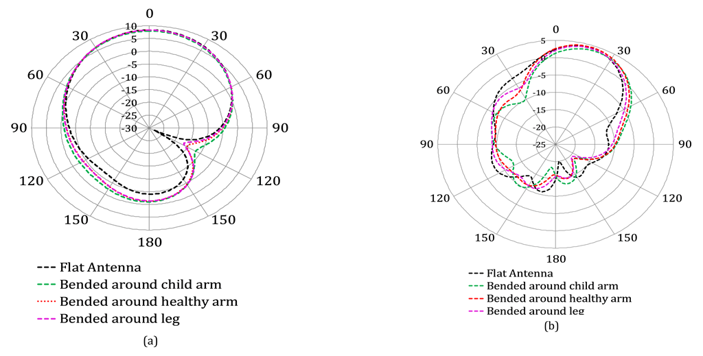
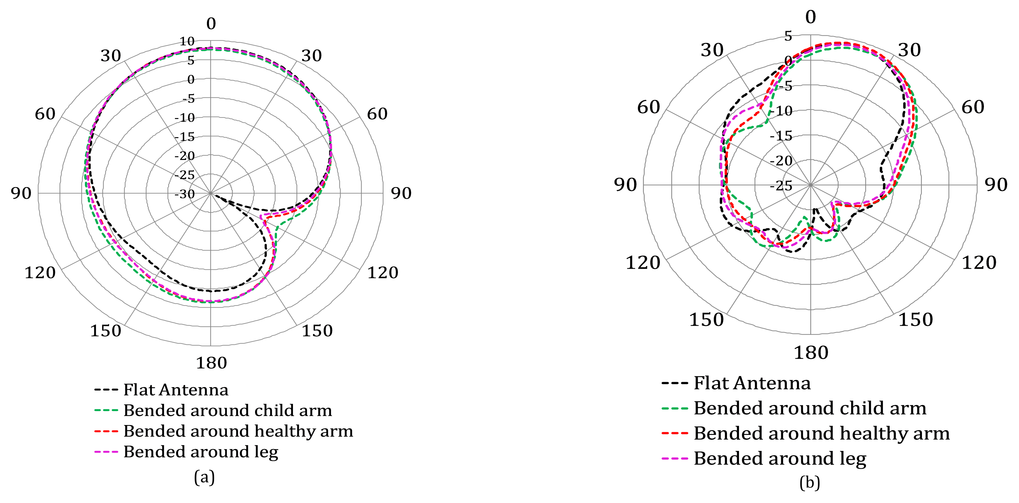
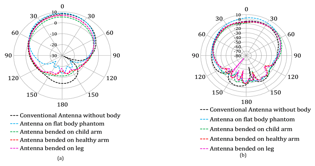
3.2.2. Directivity and Gain Patterns

The directivity and gain patterns of the designed conventional antenna, without a body and when mounted on different body parts, are shown in Figure 21 and Figure 22, respectively. These figures demonstrate that among all conditions, antenna to be placed over a flat body phantom is the most suitable choice in terms of side and back lobes. For rounded body parts, the side and back lobes decrease dramatically as the bending radius increases, and the radiation patterns approach that of the flat body condition. Table 5 presents a comparison on the basis of maximum gain and directivity between the conventional antenna without a body and the antenna with a child’s arm with a radius of 40 mm (worst case). A small amount of reduction at the lower resonance frequencies has been observed in both the maximum gain and directivity when the designed antenna is worn on a child arm (worst case).

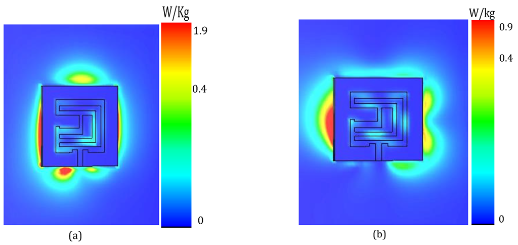
3.3. Specific Absorption Rate (SAR) Analysis of Conventional Dual Band Antenna

Whenever an antenna is installed on a human body, a part of the electromagnetic waves (EMW) radiated by that antenna is absorbed into the human body in the form of side and back lobes. The specific absorption rate (SAR) is the term used for the evaluation of the absorption of these EM waves by the wearer’s body. The SAR value must be in the RF exposure limit to ensure the wearer’s safety. However, for the frequency range of 400 MHz to 6 GHz, the ICNIRP and IEEE Std C95.1TM-2019 specifies the restriction in term of specific energy absorption (SA) of any 10-g cubic mass, where SA is restricted to 7.2 [ 0.05 + 0.95 ( t 360 ) 0.5 ] kJ kg 1 for the head and torso and 14.4 [ 0.025 + 0.975 ( t 360 ) 0.5 ] kJ kg 1 for limb exposure, where t is the exposure interval in seconds. Note that for this specification, exposure from any pulse, group of pulses, or subgroup of pulses in a train, as well as from the total (sum) of exposures (including non-pulsed EMF), delivered in t seconds, must not exceed the limit (in order to ensure that the temperature thresholds are not exceeded) [41,42].
Table 5 illustrates that when the conventional antenna is worn on a child’s arm (worst case), a small amount of reduction in maximum gain and directivity occurrs for the lower frequency band. This means that some amount of power is consumed in the child’s arm to increase the SAR level at the lower frequency band as compared to the upper frequency band. However, as shown in Figure 23, it is still in the SAR limit (<2 W/kg) because of the small amount of absorption of energy (demonstrated by the small reduction in gain and directivity at the lower resonance frequency (Table 5, 4th column). There is an increase in the maximum gain and directivity at the upper frequency band when the conventional antenna is worn on a child’s arm. Thus, as shown in Figure 24, the SAR value at the higher frequency band is much lower than that at the lower frequency band.
The SAR values at both the resonance frequencies for the conventional antenna placed on a flat body phantom are given in Figure 22. These values are 0.332 W/kg and 0.234 W/kg averaged over 10 g of tissue for the lower and upper resonance bands, respectively. In case of the conventional antenna wrapped around the rounded body parts, the worst condition (child arm) among all bending conditions gives an SAR value of 1.89 W/kg and 0.462 W/kg taken over 10 g of tissue at 2.5 GHz and 5.2 GHz, respectively, as shown in Figure 23.
The SAR analysis of the conventional dual band antenna shows that in all conditions, i.e., an antenna placed over a flat body phantom and an antenna wrapped around rounded body parts (when simulating a lower band of 2.5 GHz, a maximum allowable power of 5.7 mW and 53.8 mW was used for 1 g and 10 g, respectively; similarly, for the higher band of 5.2 GHz, a maximum allowable power of 10 mW and 90 mW was used for 1 g and 10 g, respectively), the obtained SAR value is within the RF exposure limit (<2 W/kg (European standard)) at both resonance frequencies. Hence, there is no need for EBG for the purpose of SAR. There are several reasons for the achieved lower SAR values. First, the proposed dual-band antenna has a full finite ground plane, which works as a reflector to protect the human body from radiation. Secondly, the radiation pattern of the patch antenna is perpendicular to the antenna plane. This is the reason that patch antenna is the best candidate among all types of antennas for wearable applications. Furthermore, as shown in Figure 20 and Figure 21, when the designed antenna is mounted on the body, it radiates the minimum amount of side and back lobes towards the body. Based on these results, we consider that the proposed antenna can serve as an extremely useful component of many wearable applications, which cannot compromise on safety precautions due to their utilization in health critical systems.

4. Conclusions

In this paper, the design of a compact dual-band microstrip patch antenna operating at 2.5 and 5.2 GHz has been presented and analyzed for various critical parameters. With the help of two different EBG ground planes, improvement in the overall performance (in terms of directivity, gain, efficiency and other parameters) of the proposed dual band conventional ground plane antenna has been achieved. A comparison on the basis of the performance of the conventional antenna with two different EBG inspired antennas has been made, as given in Table 4. It is observed that EBG-inspired antennas achieve better performance compared to the antenna with a conventional ground plane. In addition, we tested the proposed dual band conventional ground plane antenna in various bending conditions. Based on our results, we conclude that the designed antenna remains tuned all the time, irrespective of the bending radii. Furthermore, we studied the proposed antenna design with respect to its contact with various human body parts (such as flat and rounded body parts) and performed a detailed SAR analysis. The corresponding results reveal that at both the given resonance frequencies, the SAR value of the conventional antenna is well within the standard SAR limit (2 W/kg) prescribed by the European standards in both conditions when the antenna is placed over the flat body phantom (chest) or wrapped around the rounded body parts. Overall, we conclude that the proposed antenna design can be useful for a variety of applications including personal communications gadgets, equipment for combat and rescue operations, and health devices without compromising on the health of the wearer. An interesting future study is to ascertain the accuracy of the performance parameters by developing a wearable healthcare product to analyze the antenna performance practically.

Author Contributions

Conceptualization, F.F. and A.A.; formal analysis, F.F., A.A. and S.U.; funding acquisition, D.-Y.C. and A.A.; methodology, F.F., S.U., A.A. and D.-Y.C.; project administration, S.U. and D.-Y.C.; resources, A.A. and S.U.; software, F.F., S.U. and A.A.; supervision, S.U. and D.-Y.C.; validation, F.F., D.-Y.C. and S.U.; visualization, S.U., F.F. and. A.A.; writing—original draft, F.F., S.U. and A.A.; writing—review and editing, D.-Y.C. and S.U. All authors have read and agreed to the published version of the manuscript.

Funding

This research was supported by the Basic Science Research Program through the National Research Foundation of Korea (NRF) funded by the Ministry of Education (2022R1I1A3064544).

Institutional Review Board Statement

Not applicable.

Informed Consent Statement

Not applicable.

Data Availability Statement

Not applicable.

Conflicts of Interest

The authors declare no conflict of interest.

References

  1. Xiangfang, R.; Lei, S.; Miaomiao, L.; Xiying, Z.; Han, C. Research and sustainable design of wearable sensor for clothing based on body area network. Cogn. Comput. Syst. 2021, 3, 206–220. [Google Scholar] [CrossRef]
  2. Ali, S.M.; Sovuthy, C.; Imran, M.A.; Socheatra, S.; Abbasi, Q.H.; Abidin, Z.Z. Recent advances of wearable antennas in materials, fabrication methods, designs, and their applications: State-of-the-art. Micromachines 2020, 11, 888. [Google Scholar] [CrossRef] [PubMed]
  3. Elsheakh, D.M.; Abdallah, E.A. Different feeding techniques of microstrip patch antennas with spiral defected ground structure for size reduction and ultra-wide band operation. J. Electromagn. Anal. Appl. 2012, 4, 410–418. [Google Scholar] [CrossRef]
  4. Fallahpour, M.; Zoughi, R. Antenna miniaturization techniques: A review of topology-and material-based methods. IEEE Antennas Propag. Mag. 2017, 60, 38–50. [Google Scholar] [CrossRef]
  5. Ahmad, A.; Arshad, F.; Naqvi, S.I.; Amin, Y.; Tenhunen, H.; Loo, J. Flexible and compact spiral-shaped frequency reconfigurable antenna for wireless applications. IETE J. Res. 2020, 66, 22–29. [Google Scholar] [CrossRef]
  6. Mahfuz, M.H.; Islam, M.R.; Park, C.W.; Elsheikh, E.A.; Suliman, F.; Habaebi, M.H.; Malek, N.A.; Sakib, N. Wearable Textile Patch Antenna: Challenges and Future Directions. IEEE Access 2022, 10, 38406–38427. [Google Scholar] [CrossRef]
  7. Ali, U.; Ullah, S.; Khan, J.; Shafi, M.; Kamal, B.; Basir, A.; Flint, J.A.; Seager, R.D. Design and SAR analysis of wearable antenna on various parts of human body, using conventional and artificial ground planes. J. Electr. Eng. Technol. 2017, 12, 317–328. [Google Scholar] [CrossRef]
  8. Augustine, R.; Alves, T.; Sarrebourse, T.; Poussot, B.; Mathew, K.; Laheurte, J.M. Polymeric ferrite sheets for SAR reduction of wearable antennas. Electron. Lett. 2010, 46, 197. [Google Scholar] [CrossRef]
  9. Augustine, R.; Alves, T.; Zhadobov, M.; Poussot, B.; Sarrebourse, T.; Sauleau, R.; Thomas, M.K.; Laheurte, J.M. SAR reduction of wearable antennas using polymeric ferrite sheets. In Proceedings of the Fourth European Conference on Antennas and Propagation, Barcelona, Spain, 12–16 April 2010; pp. 1–3. [Google Scholar]
  10. Jensen, M.A.; Rahmat-Samii, Y. EM interaction of handset antennas and a human in personal communications. Proc. IEEE 1995, 83, 7–17. [Google Scholar] [CrossRef]
  11. Li, H.; Tsiaras, A.; Lau, B.K. Analysis and estimation of MIMO-SAR for multi-antenna mobile handsets. IEEE Trans. Antennas Propag. 2017, 65, 1522–1527. [Google Scholar] [CrossRef] [Green Version]
  12. Ramachandran, T.; Faruque, M.R.I.; Islam, M.T. Specific absorption rate reduction for sub-6 frequency range using polarization dependent metamaterial with high effective medium ratio. Sci. Rep. 2022, 12, 1–18. [Google Scholar] [CrossRef] [PubMed]
  13. Ramachandran, T.; Faruque, M.R.I.; Ahamed, E.; Abdullah, S. Specific absorption rate reduction of multi split square ring metamaterial for L-and S-band application. Results Phys. 2019, 15, 102668. [Google Scholar] [CrossRef]
  14. Mallik, A.; Kundu, S.; Goni, M.O. Gain and SAR improvement of a conventional patch antenna using a novel Pi-shaped DNG metamaterial. In Proceedings of the 2013 International Conference on Electrical Information and Communication Technology (EICT), Khulna, Bangladesh, 13–15 February 2014; pp. 1–6. [Google Scholar]
  15. Janapala, D.K.; Nesasudha, M.; Neebha, T.M.; Kumar, R. Specific absorption rate reduction using metasurface unit cell for flexible polydimethylsiloxane antenna for 2.4 GHz wearable applications. Int. J. RF Microw.-Comput.-Aided Eng. 2019, 29, e21835. [Google Scholar] [CrossRef]
  16. Islam, M.T.; Faruque, M.R.I.; Misran, N. Reduction of specific absorption rate (SAR) in the human head with ferrite material and metamaterial. Prog. Electromagn. Res. C 2009, 9, 47–58. [Google Scholar] [CrossRef]
  17. Potey, P.M.; Tuckley, K. Design of wearable textile antenna for low back radiation. J. Electromagn. Waves Appl. 2020, 34, 235–245. [Google Scholar] [CrossRef]
  18. Song, L.; Rahmat-Samii, Y. A systematic investigation of rectangular patch antenna bending effects for wearable applications. IEEE Trans. Antennas Propag. 2018, 66, 2219–2228. [Google Scholar] [CrossRef]
  19. El May, W.; Sfar, I.; Ribero, J.M.; Osman, L. A millimeter-wave textile antenna loaded with EBG structures for 5G and IoT applications. In Proceedings of the 2019 IEEE 19th Mediterranean Microwave Symposium (MMS), Hammamet, Tunisia, 31 October–2 November 2019; pp. 1–4. [Google Scholar]
  20. Harine, G.; Abirami, S.; Harini, B.; Florence, S.E.; Subramaniam, I. Design and Analysis of Novel EBG/AMC Unit Cell. In Proceedings of the 2019 5th International Conference on Advanced Computing & Communication Systems (ICACCS), Coimbatore, India, 15–16 March 2019; pp. 684–688. [Google Scholar]
  21. Rano, D.; Hashmi, M. Extremely compact EBG-backed antenna for smartwatch applications in medical body area network. IET Microwaves, Antennas Propag. 2019, 13, 1031–1040. [Google Scholar] [CrossRef]
  22. Zu, H.; Wu, B.; Yang, P.; Li, W.; Liu, J. Wideband and High-Gain Wearable Antenna Array with Specific Absorption Rate Suppression. Electronics 2021, 10, 2056. [Google Scholar] [CrossRef]
  23. Ahmad, A.; Choi, D.y.; Ullah, S. A compact two elements MIMO antenna for 5G communication. Sci. Rep. 2022, 12, 1–8. [Google Scholar] [CrossRef]
  24. Chen, X.; Zhang, S.; Li, Q. A review of mutual coupling in MIMO systems. IEEE Access 2018, 6, 24706–24719. [Google Scholar] [CrossRef]
  25. Mohamadzade, B.; Lalbakhsh, A.; Simorangkir, R.B.; Rezaee, A.; Hashmi, R.M. Mutual coupling reduction in microstrip array antenna by employing cut side patches and EBG structures. PRogress Electromagn. Res. M 2020, 89, 179–187. [Google Scholar] [CrossRef]
  26. Khan, A.; Bashir, S.; Ghafoor, S.; Qureshi, K.K. Mutual coupling reduction using ground stub and EBG in a compact wideband MIMO-antenna. IEEE Access 2021, 9, 40972–40979. [Google Scholar] [CrossRef]
  27. Acharjee, J.; Mandal, K.; Mandal, S.K. Reduction of mutual coupling and cross-polarization of a MIMO/diversity antenna using a string of H-shaped DGS. AEU-Int. J. Electron. Commun. 2018, 97, 110–119. [Google Scholar] [CrossRef]
  28. Trivedi, K.; Pujara, D. Mutual coupling reduction using defected ground structure in UWB DRA array for MIMO application. In Proceedings of the 2020 IEEE International Symposium on Antennas and Propagation and North American Radio Science Meeting, Montreal, QC, Canada, 5–10 July 2020; pp. 1879–1880. [Google Scholar]
  29. Ahmad, U.; Ullah, S.; Rafique, U.; Choi, D.Y.; Ullah, R.; Kamal, B.; Ahmad, A. MIMO Antenna System With Pattern Diversity for Sub-6 GHz Mobile Phone Applications. IEEE Access 2021, 9, 149240–149249. [Google Scholar] [CrossRef]
  30. Hossain, M.; Faruque, M.R.I.; Islam, M.T. Analysis on the effect of the distances and inclination angles between human head and mobile phone on SAR. Prog. Biophys. Mol. Biol. 2015, 119, 103–110. [Google Scholar] [CrossRef]
  31. Yalduz, H.; Tabaru, T.E.; Kilic, V.T.; Turkmen, M. Design and analysis of low profile and low SAR full-textile UWB wearable antenna with metamaterial for WBAN applications. AEU-Int. J. Electron. Commun. 2020, 126, 153465. [Google Scholar] [CrossRef]
  32. Abbas, S.M.; Ranga, Y.; Esselle, K.P. Sensitivity of a wearable printed antenna with a full ground plane in close proximity to human arm. In Proceedings of the 2015 9th European Conference on Antennas and Propagation (EuCAP), Lisbon, Portugal, 12–17 April 2015; pp. 1–4. [Google Scholar]
  33. Elias, N.; Samsuri, N.; Rahim, M. Analytical study of energy absorption in human body due to bendable behaviour of textile antenna. In Theory and Applications of Applied Electromagnetics; Springer: Berlin/Heidelberg, Germany, 2015; pp. 329–337. [Google Scholar]
  34. Pandimadevi, M.; Tamilselvi, R.; Parisa Beham, M. Design and simulation of flexible jute antenna with performance validation on bending and soaking conditions. Text. Res. J. 2021, 91, 219–231. [Google Scholar] [CrossRef]
  35. Balanis, C.A. Antenna Theory: Analysis and Design; John Wiley & Sons: Hoboken, NJ, USA, 2015. [Google Scholar]
  36. Ahmad, A.; Faisal, F.; Khan, S.; Ullah, S.; Ali, U. Performance analysis of a wearable and dual band planar antenna using a mushroom-like electromagentic bandgap (EBG) ground plane. In Proceedings of the 2015 International Conference on Open Source Systems & Technologies (ICOSST), Lahore, Pakistan, 17–19 December 2015; pp. 24–29. [Google Scholar]
  37. Faisal, F.; Ahmad, A.; Ali, U.; Ullah, S.; Ullah, K. Performance analysis of a 2.4 GHz planar antenna using different types of wearable artificial ground planes. In Proceedings of the 2015 12th International Conference on High-capacity Optical Networks and Enabling/Emerging Technologies (HONET), Islamabad, Pakistan, 21–23 December 2015; pp. 1–5. [Google Scholar]
  38. Saraereh, O.A. Microstrip wearable dual-band antenna design for ON body wireless communications. In Proceedings of the 2019 IEEE 4th International Conference on Computer and Communication Systems (ICCCS), Singapore, 23–25 February 2019; pp. 585–589. [Google Scholar]
  39. Hasan, M.; Faruque, M.R.I.; Islam, M.T. Dual band metamaterial antenna for LTE/bluetooth/WiMAX system. Sci. Rep. 2018, 8, 1–17. [Google Scholar] [CrossRef]
  40. Sankaralingam, S.; Gupta, B. Development of textile antennas for body wearable applications and investigations on their performance under bent conditions. Prog. Electromagn. Res. B 2010, 22, 53–71. [Google Scholar] [CrossRef]
  41. International Commission on Non-Ionizing Radiation Protection (ICNIRP). Guidelines for limiting exposure to electromagnetic fields (100 kHz to 300 GHz). Health Phys. 2020, 118, 483–524. [Google Scholar] [CrossRef]
  42. Bailey, W.H.; Bodemann, R.; Bushberg, J.; Chou, C.K.; Cleveland, R.; Faraone, A.; Foster, K.R.; Gettman, K.E.; Graf, K.; Harrington, T.; et al. Synopsis of IEEE Std C95. 1™-2019 “IEEE Standard for Safety Levels With Respect to Human Exposure to Electric, Magnetic, and Electromagnetic Fields, 0 Hz to 300 GHz”. IEEE Access 2019, 7, 171346–171356. [Google Scholar] [CrossRef]
Figure 1. Geometrical model of the proposed dual band microstrip patch antenna.
Applsci 12 09218 g001
Figure 2. EBG unit cells. (a) Mushroom-like EBG unit cell. (b) Unit cell with plus-shaped slots.
Applsci 12 09218 g002
Figure 3. In-phase reflection of EBG unit cells. (a) Mushroom-like unit cell. (b) Unit cell with plus-shaped slots.
Applsci 12 09218 g003
Figure 4. A 5×5 array of (a) the mushroom EBG and (b) the EBG with plus-shaped slots with suspended strips.
Applsci 12 09218 g004
Figure 5. Reflection and transmission coefficients of 5 × 5 EBG array. (a) Mushroom-like EBG unit; (b) EBG with plus-shaped slots.
Applsci 12 09218 g005
Figure 6. Antenna over EBG ground planes. (a) Mushroom-like EBG; (b) EBG with plus-shaped slots.
Applsci 12 09218 g006
Figure 7. Overall flat body phantom used for modeling the typical human chest.
Applsci 12 09218 g007
Figure 8. Antenna wrapped around four-layered body parts. (a) Leg of radius 70 mm; (b) arm of radius 60 mm; (c) arm of radius 40 mm.
Applsci 12 09218 g008
Figure 9. Reflection coefficient of conventional dual band antenna.
Applsci 12 09218 g009
Figure 10. VSWR of conventional dual band antenna.
Applsci 12 09218 g010
Figure 11. Directivity patterns of conventional dual band antenna at (a) 2.5 GHz (b) 5.2 GHz.
Applsci 12 09218 g011
Figure 12. Gain patterns of conventional dual band antenna at (a) 2.5 GHz and (b) 5.2 GHz.
Applsci 12 09218 g012
Figure 13. Distribution of surface currents of the conventional dual band antenna at (a) 2.5 GHz and (b) 5.2 GHz.
Applsci 12 09218 g013
Figure 14. Return loss without EBG and with EBG ground planes.
Applsci 12 09218 g014
Figure 15. Directivity patterns with and without EBG ground planes at (a) 2.5 GHz and (b) 5.2 GHz.
Applsci 12 09218 g015
Figure 16. Gain patterns without and with EBG ground planes at (a) 2.5 GHz and (b) 5.2 GHz.
Applsci 12 09218 g016
Figure 17. Off-body reflection coefficient of the conventional dual band antenna.
Applsci 12 09218 g017
Figure 18. Off-body directivity patterns of the conventional dual band antenna at (a) 2.5 GHz and (b) 5.2 GHz.
Applsci 12 09218 g018
Figure 19. Off-body gain patterns of the conventional dual band antenna at (a) 2.5 GHz and (b) 5.2 GHz.
Applsci 12 09218 g019
Figure 20. On-body return loss of conventional dual band antenna.
Applsci 12 09218 g020
Figure 21. On-body directivity patterns at (a) 2.5 GHz and (b) 5.2 GHz.
Applsci 12 09218 g021
Figure 22. On-body gain patterns at (a) 2.5 GHz and (b) 5.2 GHz.
Applsci 12 09218 g022
Figure 23. Conventional antenna SAR value on a flat body phantom at (a) 2.5 GHz and (b) 5.2 GHz.
Applsci 12 09218 g023
Figure 24. Conventional antenna’s SAR value on a child’s arm (worst case) of radius 40 mm at (a) 2.5 GHz and (b) 5.2 GHz.
Applsci 12 09218 g024
Table 1. List of simulation parameters along with their optimized values.
ParameterDescriptionValue
(mm)
ParameterDescriptionValue
(mm)
lsSubstrate or ground
plane length
68gGap at sides of the feed line5
wsSubstrate or ground
plane width
73stDepth of the gap with the feed line3.5
lpPatch length44.75cRight side cut length10
wpPatch width47w1Width of the upper
or centered or bottom strip
5
hSubstrate thickness3w2Width of the right
or left side strip
3.5
mtPatch or ground
plane thickness
0.03w3Width of the p shaped cut9
lfMicrostrip feed line length15.125w4Width of the I shaped cut12
wfMicrostrip feed line width5l1Length of the I shaped cut26
Table 2. Summary of the EBG unit cells dimensions.
Typelu (mm)g1 (mm)g2 (mm)h (mm)r (mm)l (mm)w (mm)Periodicity
Mushroom-like
EBG unit cell
32.521.531.5 32.5
Plus-shaped slot
EBG unit cell
26.50.51.13 13326.5
Table 3. Average EM properties of human tissues at 2.5 GHz and 5.2 GHz.
TissueConductivity (2.5 GHz), S/m ϵ r /2.5 GHzConductivity (5.2 GHz), S/m ϵ r /5.2 GHz
Bone0.3845911.411.01019.946
Muscle1.70552.794.266949.278
Fat0.102355.280.25475.0104
Skin1.440738.063.218535.61
Table 4. Performance comparison of proposed dual band antennas with and without EBG ground planes.
ParameterConventional
Dual Band
Antenna
Mushroom-like
EBG-Based
Antenna
EBG with Plus-
Shaped Slots-
Based Antenna
Frequency (GHz)2.55.1962.4525.1922.5285.208
Bandwidth (MHz)23.860.4299431.777.1
Return loss (dB)−24.975−28.234−19.82−24.41−24.06−19.25
Directivity (dB)8.399.018.5511.69.669.33
Gain (dBi)8.088.748.4311.49.439.14
Radiation Efficiency (%age)93.0693.9497.4396.1794.8995.71
Total efficiency (%age)92.7693.8096.4195.8294.5294.58
Angular width (Deg)83.476.980.299.462.870.2
Table 5. Maximum gain and directivity comparison between conventional antenna without a body and with a child’s arm.
ParameterConventional Antenna
without Body
Conventional Antenna
Bent Around
Arm of Radius 40 mm
Frequency (GHz)f1 = 2.5f2 = 5.196f1 = 2.508f2 = 5.224
Gain (dBi)8.088.746.689.01
Directivity (dB)8.399.017.79.29
Publisher’s Note: MDPI stays neutral with regard to jurisdictional claims in published maps and institutional affiliations.

