Abstract
Although water is the second most important fluid, after air, found on the Earth, there is a vital problem in the availability of water for many organisms, and this problem faces the whole world. As a result, scientists have developed many methods of purifying the saline/brackish water to be suitable for different uses in addition to the purpose of drinking. Fortunately, solar distillation is very rewarding in terms of operating costs and costs for a liter of freshwater distillated with using clean and environmentally friendly energy. Solar distiller is one of the solar distillation systems devices, which is simple in construction, cheap, and easy to use but it has the drawback of low productivity. This article aims to provide a summary of the different ideas and works on solar stills through different variables that affect the performance of distillers. In contrast to the review papers dealing with this topic, this paper contains comprehensive and complete details and careful reviews of all the variables that affect the performance of distillers. Therefore, it is like a ladder in front of the authors until they reach the recent of what has been studied on the distillers in a simplified way to save time and effort, which will help them to come up with different ideas that were not easily studied. Thus, this paper introduces an overview on the detailed parameters affecting the performance of solar stills. These parameters are climatic, design, and operating factors. Climatic factors consist of solar radiation, ambient temperature, air speed, and dusty and cloudy weather. While the design factors include the evaporative and exposure surface areas, glazing cover material, inclination, and thickness, distiller material, and of insulating material and thickness. Whist, the operating parameters consist of the water temperature, feed water temperature, applying vacuum, temperature difference between water and glass cover, and hybrid systems. From the extensive literature, it is concluded that the climatic, design, and operating factors significantly affect the performance of the solar still. Finally, some points are proposed for further investigation.
1. Introduction
As well known, the basic birthrights of human are the clean air, clean water, healthy food, and green energy. Therefore, clean water is the second important need of all living organisms on Earth [1]. Additionally, the water is the second most important fluid, after air, for the continuity of humanity. Our bodies contain two-thirds of their weight in water. Our brain, lungs, and blood have 95%, 90%, and 82% water, respectively. To understand the importance of water to our human bodies, a deficiency of just 2% in our body’s water supply indicates a dehydration in the same body. Furthermore, many functions in the human body rely on the existence of water such as the blood circulation, growing tissues, digestion, transporting nutrients, waste removal process, and keeping body temperature balanced. As a result, the people can survive without food for a longer period, but they cannot live without water for few days. These facts reveal the importance of water in the world of people.
Despite the importance of clean water for our lives (as explained above), only 0.01% is available as a surface water like the rivers, lakes, and swamps, which can be directly used by humans [2]. Other potable water with a percentage of ~2.5–2.8% of earth’s water can be found in the forms of soil moisture and groundwater or frozen state (ice, glaciers, and snow). While the remaining earth’s water (~97% of earth’s water) is saline/brackish water such as the sea water, ocean water, and underground water, which requires treatment processes to be used by humans. Due to these facts about plant water, more than 785 million populations do not have access to drinkable water. Moreover, a horrible number of 6–8 million people, all over the world, die every year because of disasters and water-related health problems. These frightening facts have made it a national and humanitarian duty for scientists to research how to overcome the water problem and how to provide alternative sources of safe drinking water using renewable energies. One of the well-known methods to overcome the potable water shortage problem is the saline/brackish water desalination. Moreover, the permissible limits of the potable drinkable water are specified by the related agencies as tabulated in Table 1 [3]. As a result, there are various types of desalination methods that achieve the drinkable water requirements and provide freshwater for the areas that are in need. Therefore, the desalination as a solution for potable water shortage problem will be discussed in the next section.

Table 1.
Chemical and physical properties of the qualified potable water.
2. Desalination as a Solution for Potable Water Shortage Problem
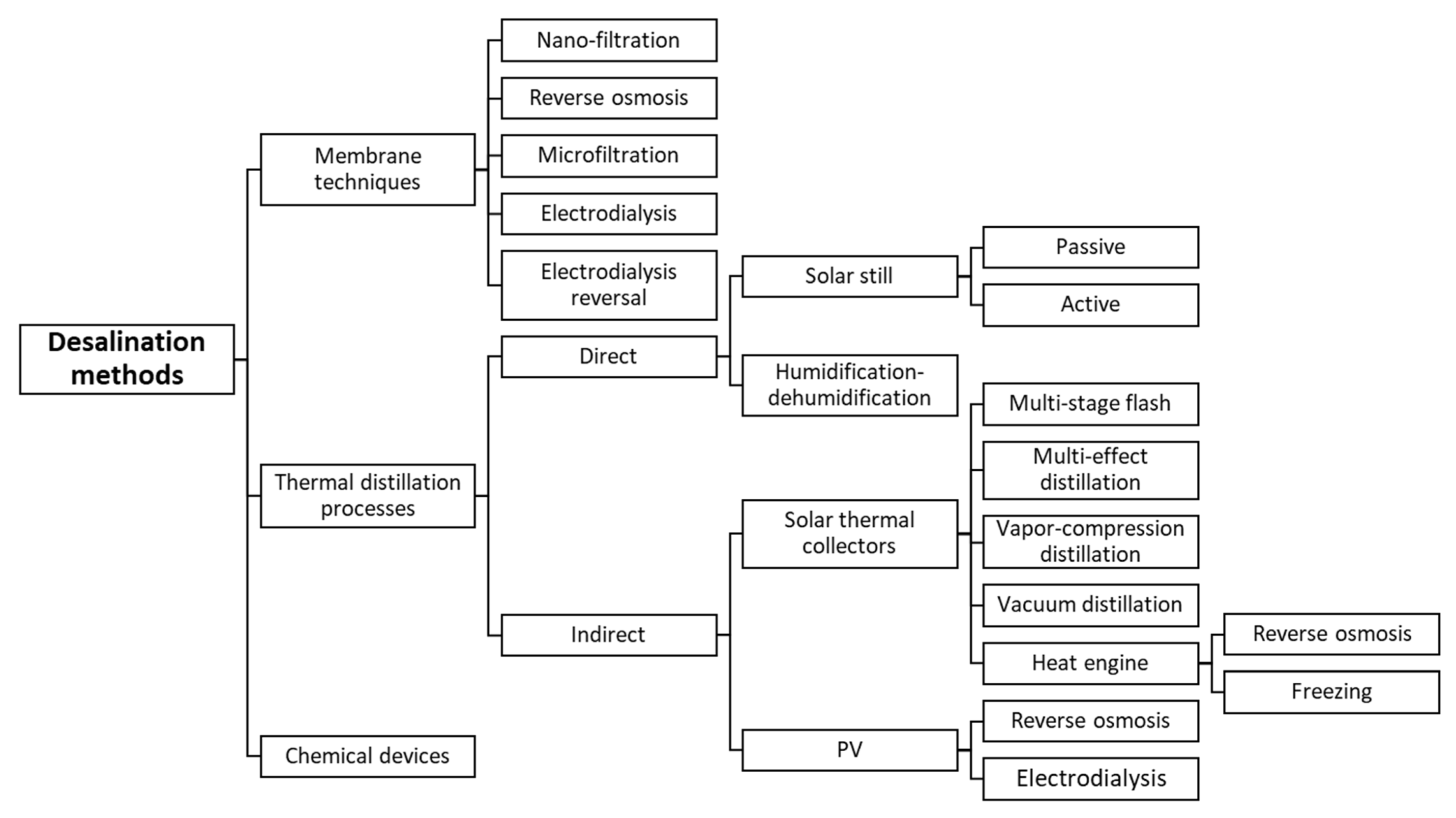
With the progress of technology, many industrial and commercial devices are used to purify the saline/brackish water and produce potable water. These devices can purify any kind of contaminated water. Therefore, they are suitable to be used at homes, hotels, schools, and so on. The water purification devices are classified into three main categories: membrane techniques (single phase processes), thermal distillation processes (phase change processes), and chemical devices, as illustrated in Figure 1.
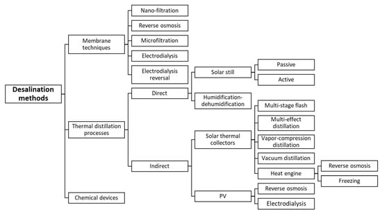
Figure 1.
Classification of desalination methods.
2.1. Membrane Techniques (Single Phase Processes)
This technology contains series of processes, and the membrane is a main component of every process. Using the membrane is familiar in the industry of polluted water filtration because it removes harmful agents. This method is used on a large scale because it can filter the polluted water with various sizes of contaminated impurities. As a result, we found the nano-, ultra-, and micro-filtration filters, which can remove the particles, macromolecules, colloids, and other infection-causing agents.
The filtration mechanism of the membrane depends mainly on the thin-porous films which are fabricated from nylons, acetate, ceramics, or cellulose. These films are crossed only by water molecules, and filter contaminant agents, pollutants, or bacteria, toxic chemicals, highly concentrated salts, and metals. Thus, a safe potable water is obtained. Based on the commercial reports, the membrane technologies are classified into pressure driven technologies and electricity driven technologies. The pressure driven technologies include the microfiltration (MF), ultrafiltration (UF), nanofiltration (NF), hyperfiltration (HF), and reverse osmosis (RO) processes. Whereas, the electricity-driven technologies include the electrodialysis (ED) and electrodialysis reversal (EDR) [1].
2.1.1. Reverse Osmosis
The phenomenon of osmosis is the base of the RO mechanism. It means that the salt concentration (ppm or mg/L) is removed from the polluted water (contaminated water) via creating an osmotic pressure change between the salt and the fresh potable water. Here, the reverse flow is an important parameter in the RO process. To control this parameter, a pressure higher than the osmotic pressure is applied on the flow so that the freshwater molecules are filtered from the contaminated water and passed through the membrane pores of the RO unit. RO units can be used to purify both brackish water and seawater because they can filter the salt concentrations ≤45,000 ppm. In addition, RO requires an energy amount proportion to the salt concentration of the feed water.
2.1.2. Nano-Filtration
As well known, the membrane pour size controls the filtration quality and the percent of removing the contaminated agents from the polluted water. NF is suitable for filtering the high concentrations from the contaminated feed water. Moreover, the size of the membrane rangea between 0.05 µm and 0.005 µm. Thus, the pressure needed for operating the NF unit ranges between 500 kPa and 1000 kPa because the size of membrane pores is large. Moreover, the required pressure for the filtration process depends on the size of the membrane pores. As a result, the pressure required to operate the HF unit (1000–5000 kPa) is higher than that required to operate the NF unit and greater than that required to operate the MF and UF units too (30–500 kPa). Additionally, for low total dissolved solids (TDS) or low salt in the feed water, NF treatment only is enough to produce a potable water. This technology (NF) is the most reliable and effective technology among the pressure-driven membrane technologies for filtering the undesired contaminated agents such as bacteria, metals, high TDS, and toxic chemicals, etc. For instance, Zhou et al. [4] introduced new T-C3N monolayer with suitable pore size (5.50 Å), which can reject all inorganic salt ions as well as organic contaminants in water and be suitable for water permeability.
2.1.3. Electrodialysis
As explained above, ED is a membrane process under the classification of electricity driven technologies. Here, in the ED process, the electricity (electric current) is the driven force that is utilized to filter the polluted water and remove salt content from the feed water through the membrane (thin-film porous membrane). To illustrate how this method works, an electromotive force is employed to electrodes close to both sides of the membrane. Then, when employing a voltage difference, the ion-filter membrane separates the salt ions from the polluted water. Hence, a freshwater is obtained. The energy needed to operate this ED unit is proportional to the quantity of salt in the polluted water. Scientific, commercial, and industrial reports obtained that ED ad EDR are more effective for purifying the brackish water with TDS ≤ 35,000 ppm. Nevertheless, the high cost of both methods (ED and EDR) is the main limitation in front of considering them for applications.
2.2. Thermal Distillation Processes (Phase Change Processes)
From its name, the thermal distillation processes rely on changing the physical state of feed polluted water. The fundamental idea of thermal distillation processes is the process of evaporation and condensation to get potable freshwater. The thermal distillation units are suitable for purifying the seawater. These thermal distillation devices can be categorized into two main classifications: indirect and direct thermal processes. The indirect thermal devices include the multi-stage flash (MSF), multi-effect distillation (MED), vapor-compression distillation (VCD), vacuum distillation (VD), and freezing. The direct thermal devices include the humidification-dehumidification (HDH) and solar still (SS) units
2.2.1. Multi-Stage Flash
MSF is a recent technology used to distillate the seawater, and it actively contributes to the desalination community all over the world. Nowadays, MSF plants produce around 60–65% of the distilled water all over the world. MSF unit includes a specific number of stages with two ends: hot end and cold end. These stages have a heat exchanger and condensed water collectors. The condensed water collectors are placed on the inner walls of the stages.
To explain how this method works, the general working principles are listed. First, the pressure and saturation temperature inside every stage are fewer than those of the previous unit stage. Additionally, the pressure inside every stage is determined according to the boiling conditions of heated contaminated water at the stage saturation temperature. Thus, this unit needs pressure gradient between each of the two successive stages. MSF needs an external source of heating especially for the first stage. Moreover, this method works based on the desalination process that occurs by flashing (relinquish of heat) some quantity of polluted water into multiple stages. The pressure of the first stage is low to cause the evaporation process. After that, in the coming stages, the polluted water is flashed quickly and changed into vapor. Finally, the temperatures of the brine and condensed water are equal to that of the inlet feed water. The number of stages, skilled operators, and maintenance cost are the main parameters that affect the efficacy of MSF unit.
2.2.2. Multi-Effect Distillation
MED is a thermal desalination process that works at low operating temperatures. This unit works with multiple stages of processes or effects. The distillate is collected from condensing the generated vapor of the saline water when boiling it through series of effects. Each effect of distillation works at higher temperature than the next stage. The hot steam heats up the saline water and generates a vapor inside the tubes of stages. Then, the steam and generated vapor are the driver force for heating the water and generating vapor from the next stages.
With decreasing the pressure from one stage to another (this means that the boiling limit declines), the water of a stage is heated by the latent heat released by the generated vapor of the previous stage/process. The MED unit works at low temperatures (<70 °C), and it has a low maintenance cost. It is also easy to operate. One more merit of MED is that it needs few quantities of energy compared to the other thermal desalination processes like MSF. Finally, MED does not require a pre-treatment of the feeding saline water.
2.2.3. Vapor-Compression Distillation
Here, in the vapor-compression distillation (VCD) process, and from its name, the vapor is compressed, and its vaporization latent heat is utilized to evaporate the polluted water. In the first stage of this process, the temperature and pressure of the vapor are increased by the compressor (compression process of the vapor). As a result, when condensing that vapor, its released latent heat is reutilized to generate more vapor. The compression process is performed by an electrically driven mechanical device (in most cases).
VCD has many merits such as low energy consumption and maintenance charges, high reliability, being easy to operate, simple to clean, and high freshwater productivity. Additionally, starting to operate with mechanical or electrical energy without the need for external heat source is another important advantage of the VCD process. All these advantages allowed this method to penetrate the commercial market.
2.2.4. Vacuum Distillation
The VD process has the advantage of working with and without heating. The basic fundamental of this process is that the water can boil at lower temperatures with decreasing the pressure of the contaminated saline water. As a result, the saline/brackish water can be evaporated at low temperatures, then the generated vapor is condensed to obtain potable drinkable water.
2.2.5. Freezing
The desalination using freezing has three stages conducted on the ice: formation, cleaning, and melting of the ice. Freezing process of desalination has many merits like the low energy consumptions and no need for pre-treatment. Therefore, the freezing desalination process is already applied in many plants to obtain fresh desalinated water from the polluted saline water.
2.2.6. Humidification—Dehumidification Process
The working mechanism of HDH depends mainly on the fact that air can carry significant amounts of water vapor. The carried vapor amount is proportional to the temperature of the carrier air. For instance, raising the air temperature from 30 to 80 °C could make 1 kg dry air carry 0.5 kg vapor and around 670 kcal. Thus, air can withdraw a specific amount of vapor at the expense of the sensitive heat of the salt water, which leads to cooling. After that, this carrier humid air is passed over a cooled surface to obtain the distilled water by condensation.
2.2.7. Solar Still Distillation (SSD)
The working theory of solar distiller is derived from the hydrological cycle of nature. In that cycle, the incident solar radiation is the driven force to evaporate the seawater, and the generated vapor goes up due to its low density. Cooling this vapor to its dew point starts the condensation process to obtain a clean water (rainfall) from that vapor. The same mechanism (evaporation and condensation) is applied in the solar distillation units to purify the saline/brackish water.
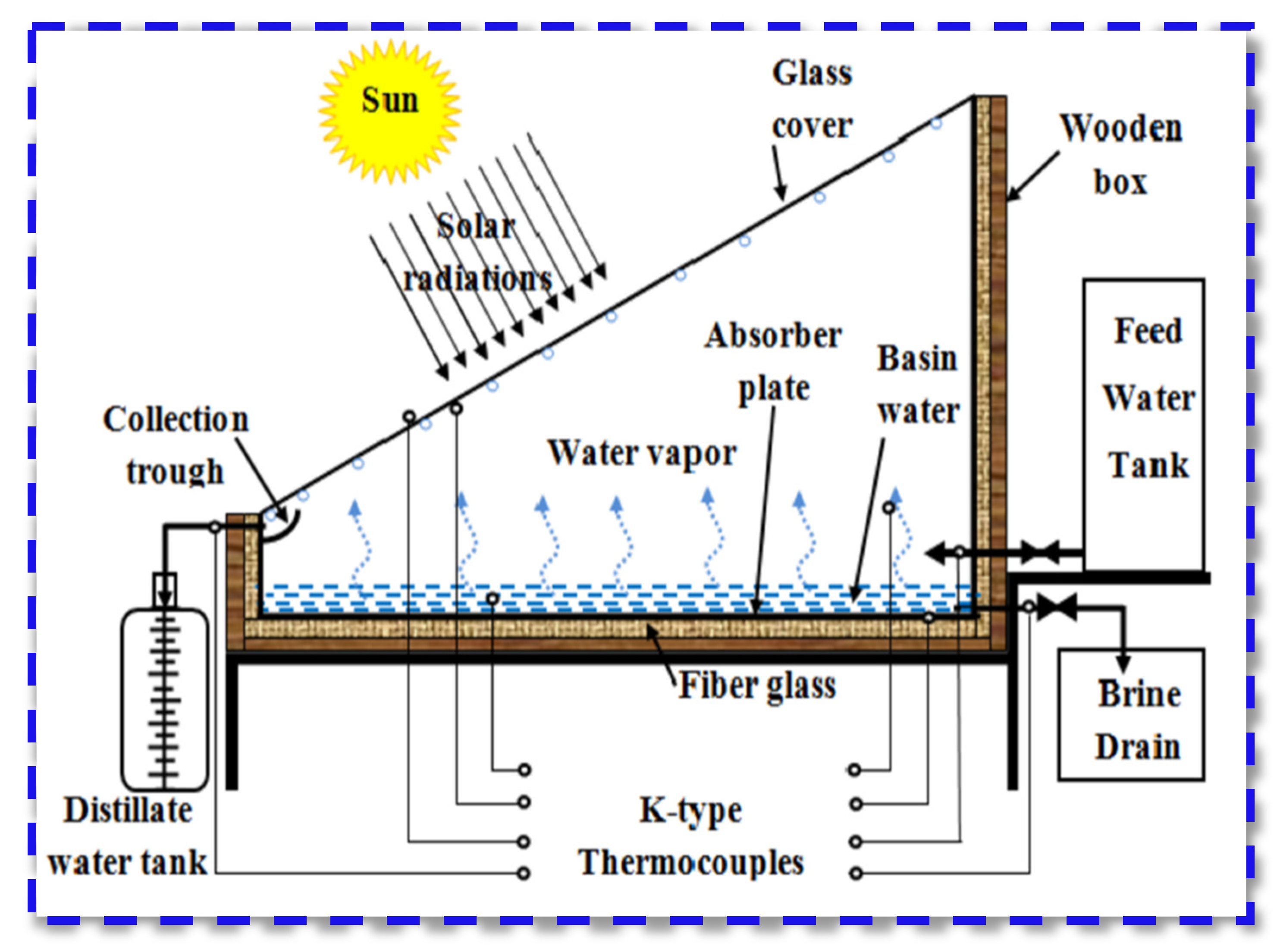
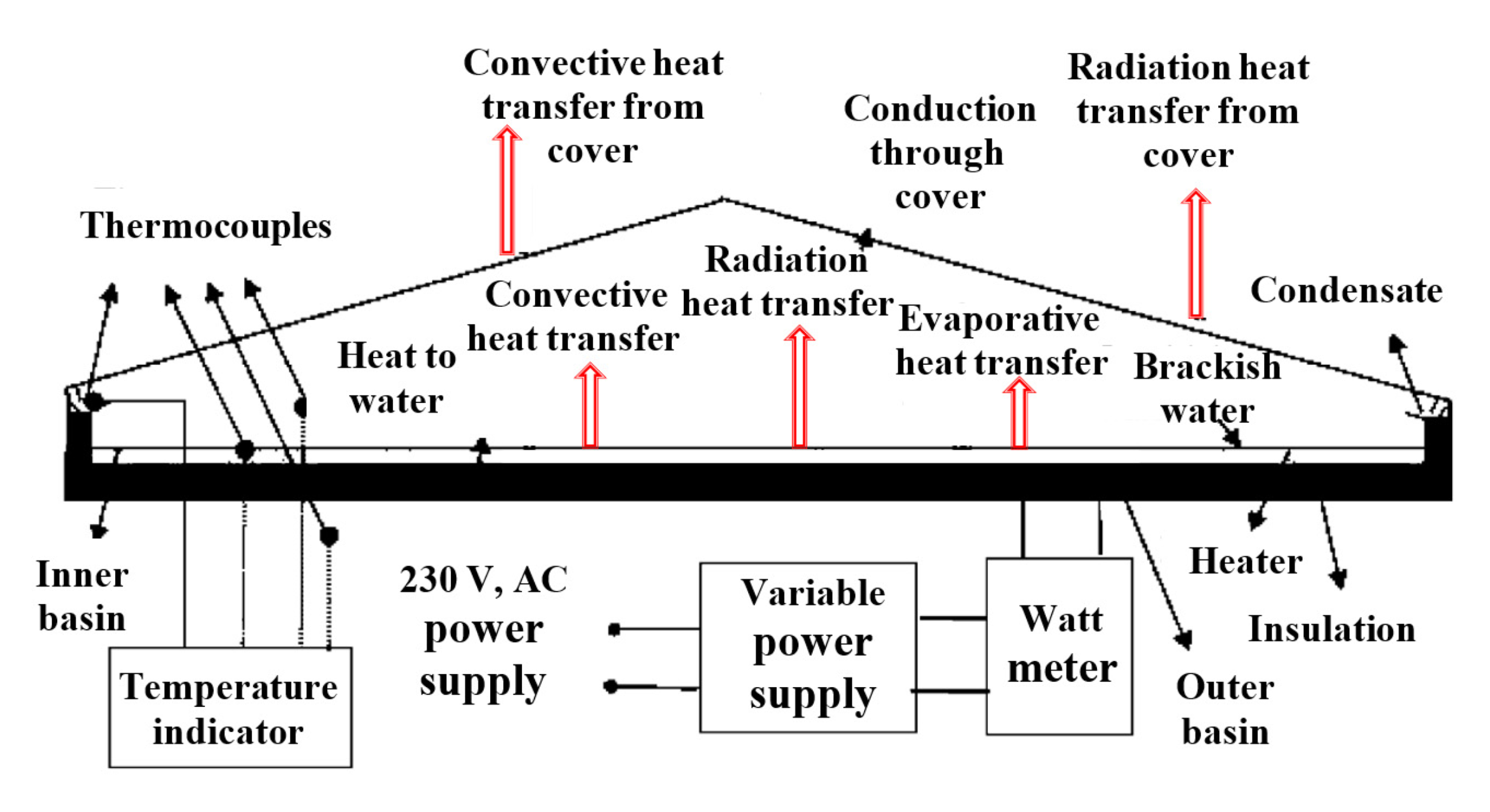
Figure 2 shows a schematic of the conventional solar still. The conventional solar still consists of a basin and covered by titled transparent glass cover. The basin has the contaminated water. The glass cover is sloped by an angle equal to the Latitude of the place of experiments. The basin contaminated water is heated up by the incident solar intensity which transmits the glass cover. The heated water begins to create vapor which rises up to be in contact with the inner surface of the glass cover. That vapor is condensed on the glass surface due to the difference between the glass and vapor temperatures. Then, the condensed droplets fall down due to gravity and tilt of glass to be collected on the distillate channel. After that, the distillate is withdrawn out of the solar still through a hose and accumulated into a graded flask, Figure 2.
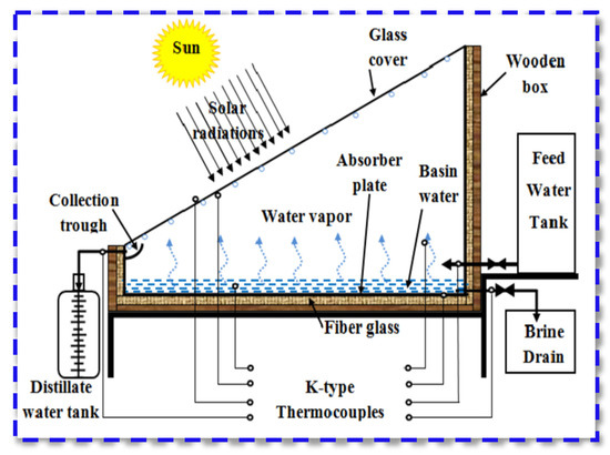
Figure 2.
Schemes of the conventional solar still.
3. Performance of Solar Stills
As is well known, the performance of the solar still depends on its daily productivity increase, thermal efficiency, and exergy efficiency. The daily productivity increment is given by the next equation.
In addition, the thermal efficiency of the solar distiller is evaluated by [5,6]:
where the latent heat (hfg) is estimated regarding the water temperature (Tw) as follows [1]:
Furthermore, the freshwater productivity is obtained by [7]:
hc,w−g is calculated by [6]:
Furthermore, the partial pressure P is estimated by:
On the other hand, the exergy analyses determine and evaluate the energy quality for the thermal devices. The ratio between the exergy output and exergy input is called the exergy efficiency (ηex) [8].
ηex = exergy output/exergy input = Ex,evap/Ex,sun
Moreover, the daily overall exergy gain is obtained by [9]:
where the water—glass evaporative heat transfer coefficient, he,w−g, is obtained by [6]:
Additionally, the exergy input () relies mainly on the solar radiation [8]:
where A, I(t), Ta, Tsun and are the distiller area (m2), solar radiation (W/m2), surrounding air temperature (K), and sun temperature (6000 K), respectively.
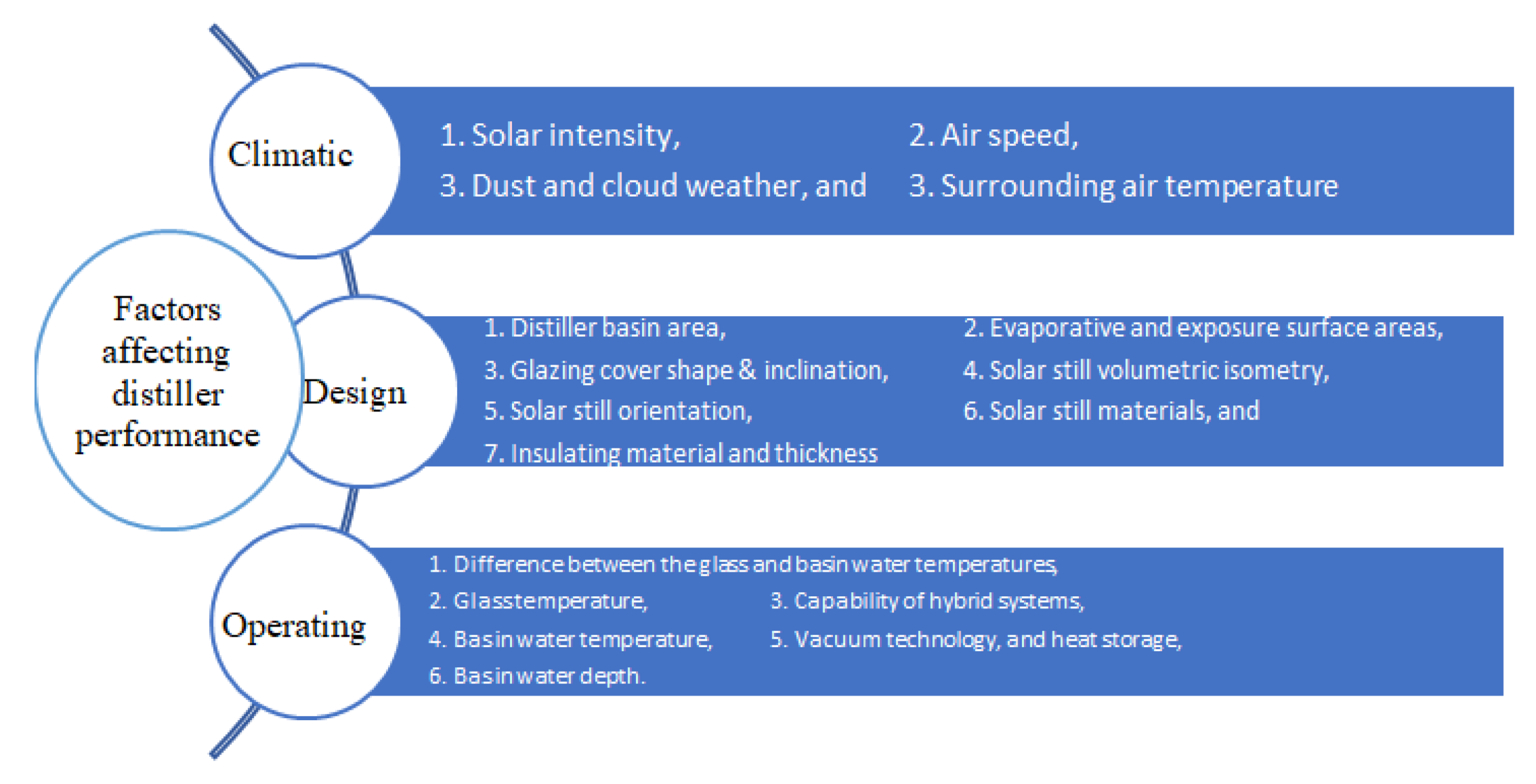
Based on the above equations, the solar still performance depends on several parameters that will be discussed in detail in this current work. These parameters include the difference between the glass and basin water temperatures, solar intensity, dusty and cloudy weather, air speed, surrounding air temperature, distiller basin area, evaporative and exposure surface areas, glazing cover inclination, capability of hybrid systems, glass temperature, basin water temperature, solar still volumetric isometry, solar still orientation, vacuum technology, heat storage, solar still materials, and insulating material and thickness. As a result, the above parameters that affect the performance of solar still can be summarized into three main general factors: climatic factors, design factors, and operating factors.
4. Factors Affecting Distiller Performance
As explained above, the factors that affect the solar still thermal performance can be categorized into climatic, design, and operating parameters. The climatic factors include the solar intensity, air speed, dusty and cloudy weather, and surrounding air temperature. Unfortunately, the climatic factors cannot be controlled. Whereas, the design factors include the distiller basin area, evaporative and exposure surface areas, glazing cover inclination, solar still volumetric isometry, solar still orientation, solar still materials, and insulating material and thickness. Moreover, the operating factors include the difference between the glass and basin water temperatures, glass temperature, capability of hybrid systems, vacuum technology, heat storage, and basin water temperature. Fortunately, the designable and operational factors are well controlled to provide superior performance of solar stills. The various factors that affect the performance of solar stills are illustrated in Figure 3. This work includes a thorough analysis of these factors that have an impact on the performance of solar still as will be discussed in the following sections.
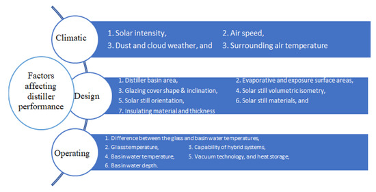
Figure 3.
The various factors that affect the performance of solar stills.
4.1. Climatic Factors
As is well known, the solar still is a device which uses the thermal energy coming from the sun as an input energy to produce potable water as an output. As a result, the input energy strongly affects the thermal performance of the solar still, which means that the thermal energy coming from the sun has a strong impact on the solar still performance. The thermal energy coming from the sun is represented and controlled by the following variables: solar intensity, air speed, dusty and cloudy weather, and surrounding air temperature. Thus, these parameters significantly affect the thermal performance of the solar stills. In addition, these parameters are the driven force to change the water–glass temperature difference, and hence change the convective and evaporative heat transfer coefficients. Despite being these meteorological factors uncontrollable, several studies have been conducted to investigate their effects on the thermal performance of the solar still. This basically will help the users to know the place to install their thermal desalination units to use the climatic parameters efficiently. The conclusions obtained by the experimental and theoretical studies conducted to investigate the effects of the meteorological factors on the solar still performance revealed that as the air speed, above a critical point, increases, the efficiency and productivity of the solar still decreases. In addition, increasing the solar radiation incident on the distillers results in an absolute increase in the freshwater productivity and thermal efficiency of the solar stills. This is simply due to the increased input energy to the solar still. Moreover, the dusty and cloudy weather affect badly the performance of the distillers as a result of diffusing the incident sun rays on the glazing cover. Consequently, the meteorological factors have a significant influence on the freshwater productivity and efficiency of the solar still as will be discussed here in detail.
4.1.1. Effect of Solar Radiation
As reported by many publications, the yield of the solar stills increases with increasing the solar radiation. All related papers concluded that the solar intensity is the most effective factor on the solar still performance [10]. Nafeya et al. [11] investigated the effect of solar radiation variations on the solar still efficiency. The authors concluded that the decline in solar intensity had reduced the distiller efficiency and vice versa. In addition, Almuhanna [12] reported the same conclusion when investigating the impact of solar radiation on the solar distiller productivity. The more the solar radiation is, the more the solar distiller productivity is. Moreover, Aburideh et al. [13] examined the influence of the environmental parameters on the performance of a double-slope distiller. The authors found that the solar intensity strongly affects the solar distiller output distillate. Additionally, Morse and Read [14] investigated theoretically the impact of the environmental parameters (solar intensity, air speed, air temperature, and heat loss changes) on the solar distiller performance. The authors found that the solar intensity was a vital factor for increasing the distiller yield. Additionally, Rahbar and Esfahani [15] stated that the solar radiation has a direct strong impact on the distiller performance.
Furthermore, Okeke et al. [16] explained the mechanism of increasing the solar still productivity with increasing the solar radiation. The authors stated that the solar intensity heats up the basin water and increases the convective heat transfer coefficient, which leads to evaporate the basin water quickly. Through the solar still device, the energy transfer processes consist of supplying the heat for basin water evaporation and removing it from generated vapor at the condensing surface (glass cover and condensers if applicable). As well known, the distiller yield increases with increasing the energy transfer rates. For more explanation, Kamal [17] concluded that the solar still productivity is much depending on the input energy, which is the solar energy (in the case of solar stills).
4.1.2. Effect of Air Temperature
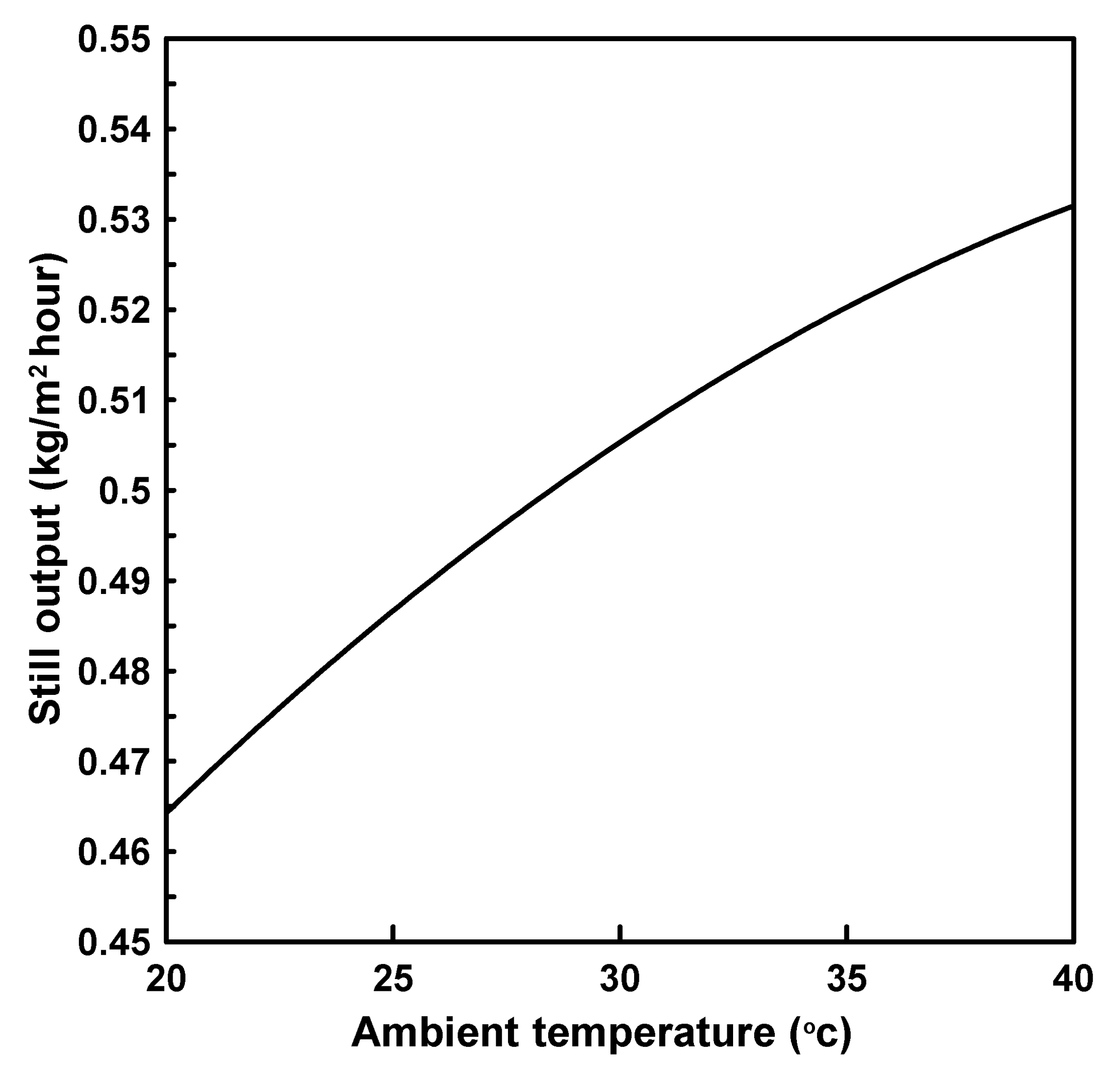
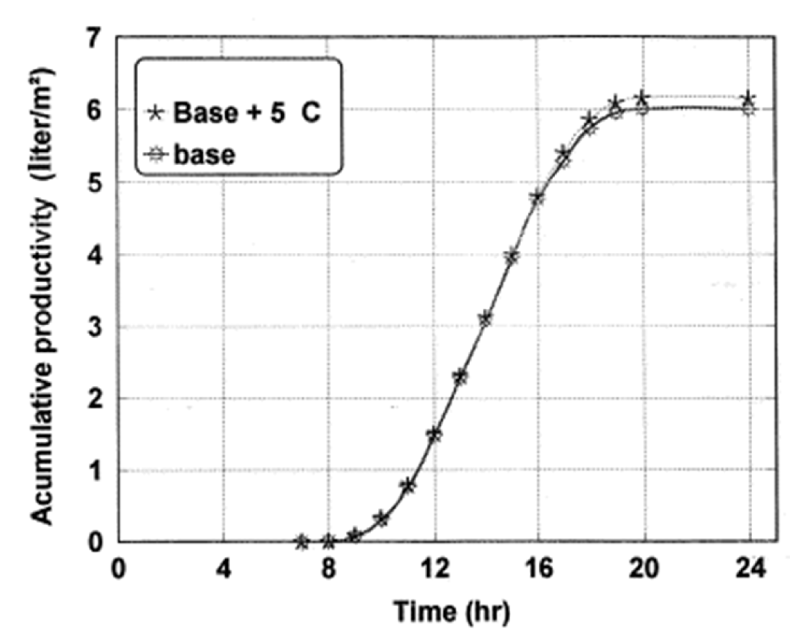
Numerous publications were conducted to investigate the influence of air temperature on the solar distiller performance. Hinai et al. [18] studied theoretically the impact of the environmental parameters such as solar radiation and temperature and speed of air on the solar distiller yield. The authors found that raising the air temperature by 10 °C (from 23 to 33 °C) increased the solar distiller productivity by around 8.2%, as illustrated in Figure 4.
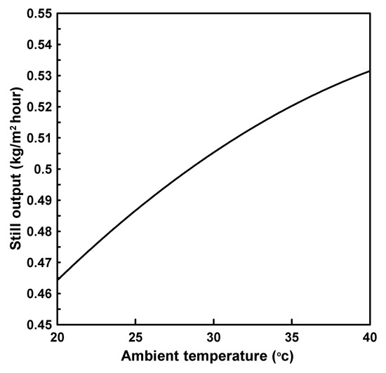
Figure 4.
Influence of ambient temperature on single distiller output [18].
In addition, Malik et al. [19] studied theoretically the effect of the ambient air temperature on the solar still performance. The authors found that a slight increase in the distiller yield (around 3%) could occur when raising the air temperature by 5 °C, as illustrated in Figure 5.
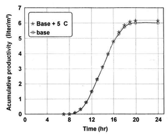
Figure 5.
Effect of air temperature on the total productivity of the distiller [19].
Moreover, Alheefi [20] investigated the influence of the air temperature on the output yield of a conventional solar still. The author reported that the temperature of the surrounding air has a significant role on the solar distiller performance and productivity, as obtained in Table 2.

Table 2.
Daily air temperature against daily total productivity [20].
4.1.3. Effect of Air Speed
Unlike the solar radiation and air temperature, the air speed has an insignificant role of the output yield of the solar distillers. This fact was affirmed by many publications [21]. As well known, the solar still yield is improved by declining the glass cover temperatures. This is because decreasing the glass cover temperatures increases the difference between the vapor and glass temperatures, which leads to enhancing the condensation process of the generated vapor on the inner surface of glass. Hence, the productivity is improved. Soliman [22] tested the impact of air speed on the performance of roof-type solar distiller with forced convection conditions. The author concluded that increasing the air speed in a parallel form to the glass cover raised the temperature difference between the water and glass, which leads to enhance the solar still productivity. Additionally, the rates of condensation and evaporation are improved with increasing the air speed. Furthermore, El-Sebaii [23] tested the influence of different air speeds on the productivity of the active and multi-effect passive stills. The author affirmed the conclusion that the distiller productivity is enhanced by increasing the ambient air speed.
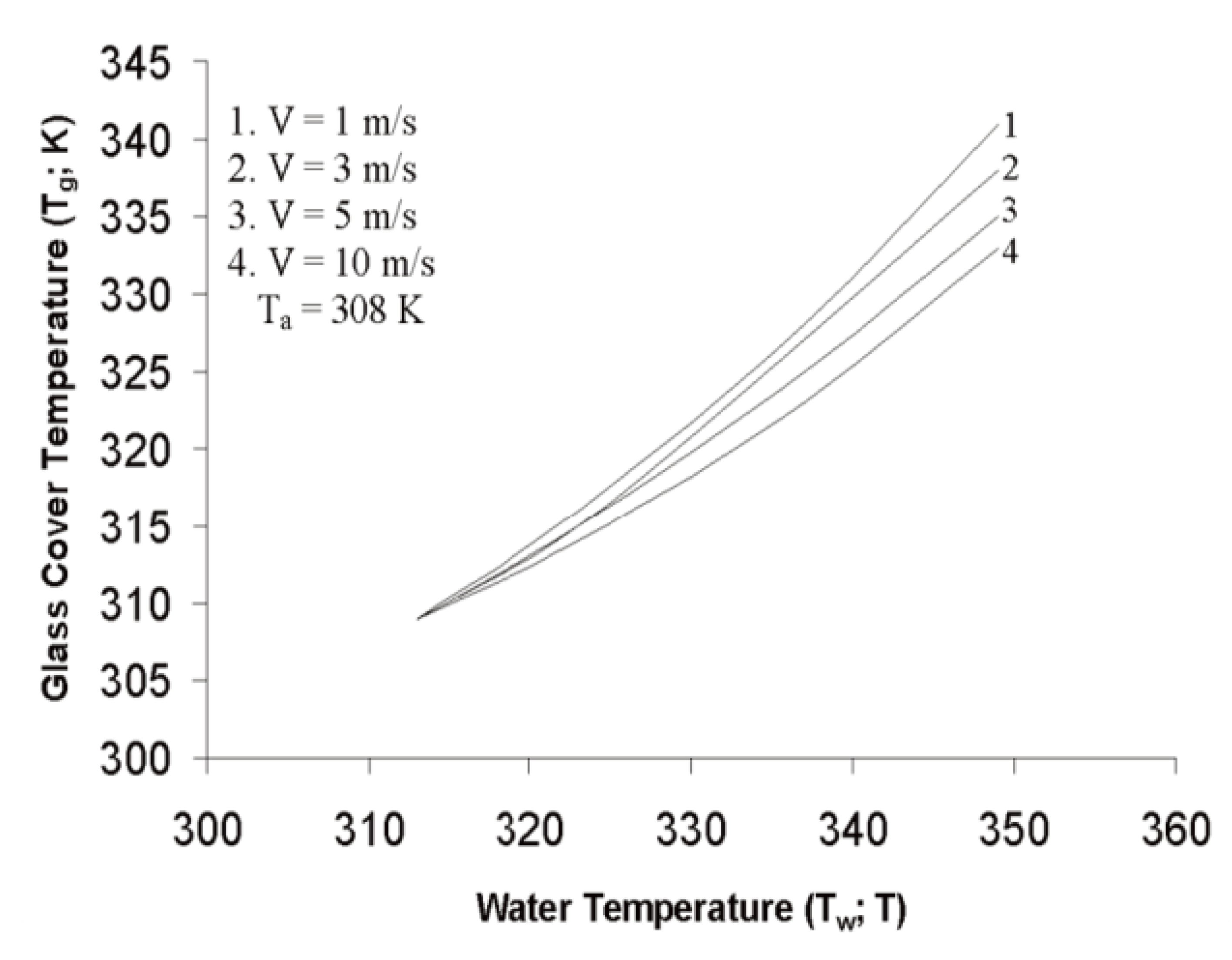
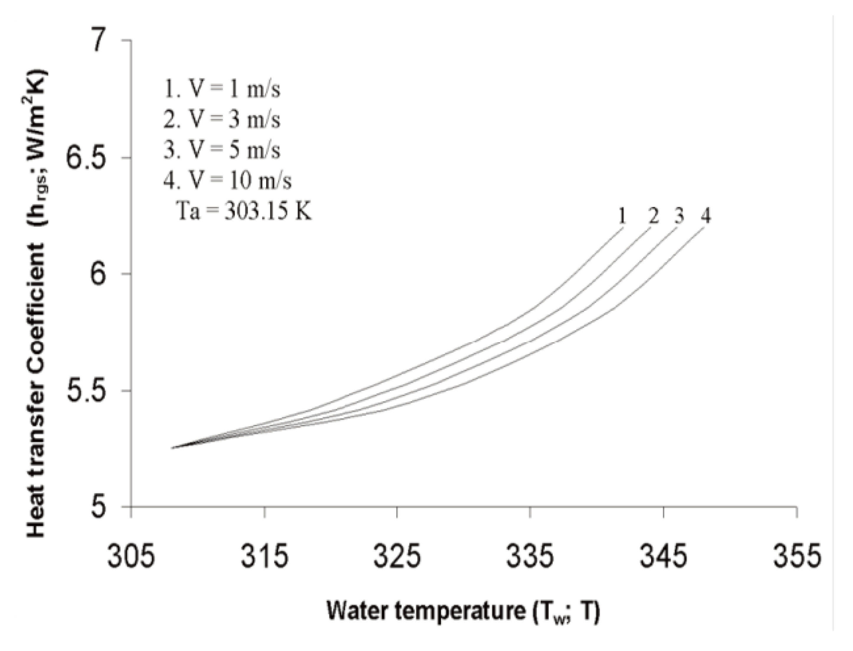
On the other hand, the solar still productivity might be declined when increasing the air speed more than a critical limit. For example, El-Sebaii [24] investigated the impact of various wind speeds on the productivity of solar still at different water depths inside the basin. The author reported that increasing the wind speed enhances the distiller performance. However, the distiller productivity decreases 13% when increasing the wind speed from 1 to 9 m/s [11]. In addition, Reddy and Reddy [25] investigated the effects of different wind speeds (from 1 to 10 m/s) on the glass temperature and heat transfer coefficients of the solar still. The authors confirmed that increasing the wind speed decreases the glass cover temperature, Figure 6. Furthermore, the authors reported that the water-glass radiative heat transfer coefficient (hr,w−g) declined with increasing the air speed, as illustrated in Figure 7. Additionally, the water–glass evaporative heat transfer coefficient (he,w−g) is not affected by changing the wind speed. Moreover, the glass–sky radiative heat transfer coefficient (hr,g−sky) declined with increasing the air speed [25].
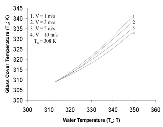
Figure 6.
Effect of air speed on glass cover temperature at different water temperatures [25].
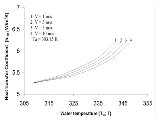
Figure 7.
Effect of air speed on water–glass radiative heat transfer coefficient at different water temperatures [25].
4.1.4. Effect of Dusty and Cloudy Weather
As is well known, the absorptivity and transmittance of the glass cover affect the performance of the solar still. In addition, the existence of the dust and dirt over the glass cover surface changes the optical properties of the glass, which affects the absorptivity and transmittance of the glass cover of the solar still [26]. Then, the productivity is changed. It was reported that the accumulation of dust and dirt over the glass surface decreases the transmittance [27]. Hottel and Woertz [28] investigated the effect of existing a dust over the glass cover of the solar systems. The authors reported a decrease in the incident solar radiation by around 1% as a loss due to the accumulation of dust and dirt over the glass surface. Moreover, El-Nashar [29] experimented with the impact of accumulating a dust on the performance of an evacuated-tubes in flat-plate type collector. It was stated that the transmittance of the glass cover drops 10% and 6% through summer and winter days, respectively. Furthermore, not cleaning the solar collector system leads to reduction of the transmittance of the glass cover by 70% [30].
4.2. Design Factors
The improvement of the solar still performance can be achieved by the modifying the designable parameters of the geometric shape and distances. The most important designable parameters that strongly affect the performance of the solar distiller are discussed in the upcoming subtitles. The design factors include the evaporative and exposure surface areas, glazing cover material, inclination, and thickness, solar still materials, solar still volumetric isometry, and insulating material and thickness.
4.2.1. Effect of Evaporative and Exposure Surface Areas
It is known that the basic idea of the solar distillers is to evaporate the basin water by the action of the incident solar energy on the water, then condense the created vapor on the inner surface of the glass of the distiller. In addition, the surface area of the basin water exposed to the solar radiation is called the evaporative surface area. Consequently, the bigger the evaporative surface area, the more the generated vapor inside the solar still, and the higher the productivity of the solar still. This could be achieved via using a wick material, sponge, jute cloth, or installing curved and circular parts inside the distiller. This fact is confirmed and explained in many publications.
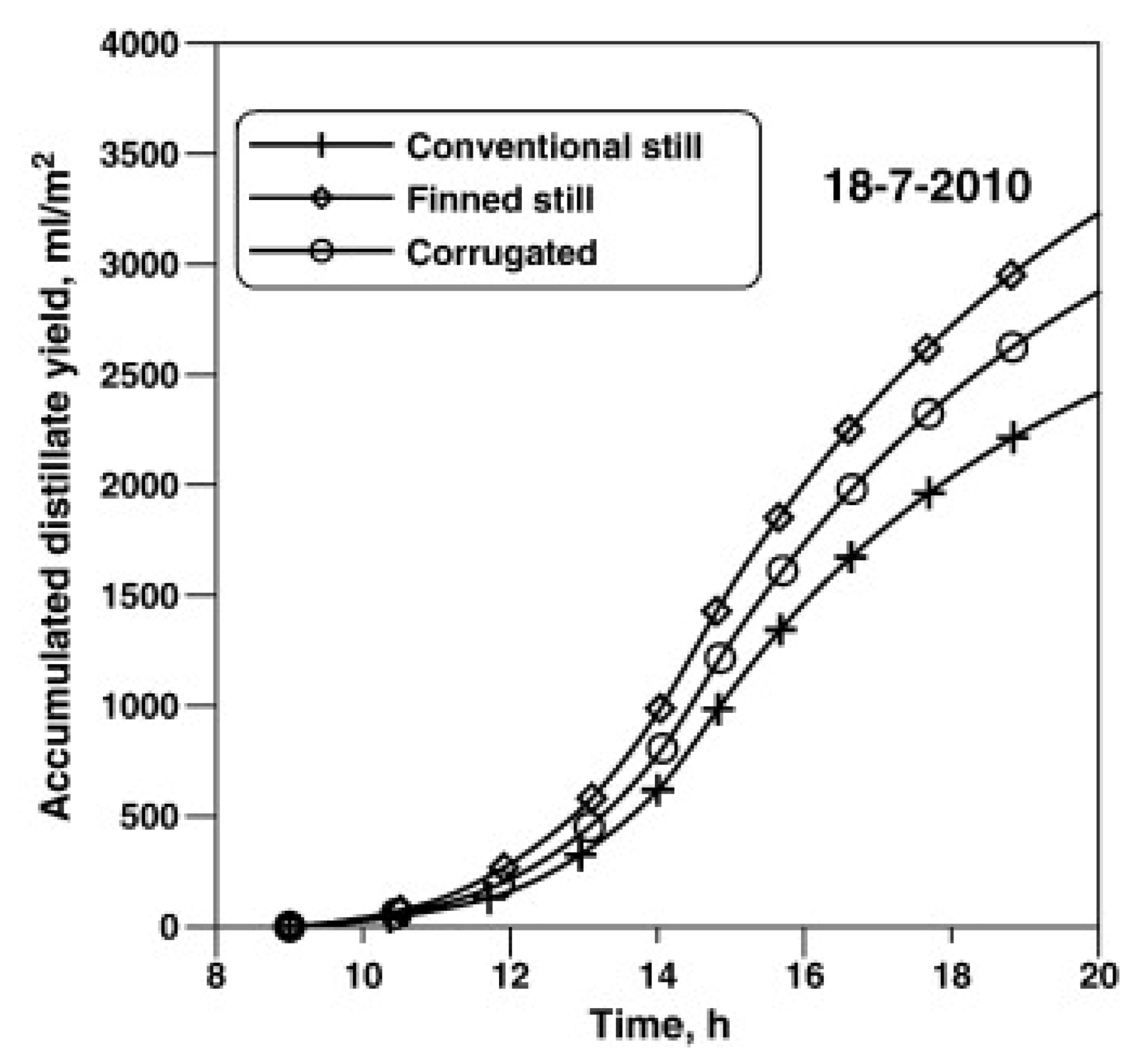
For instance, Omara et al. [31] tested the effect of installing corrugated and finned basin liners inside the solar still to increase the evaporative surface area. The authors increased the freshwater productivity of the solar still 21% and 40% when using the corrugated and finned absorbers, respectively, as illustrated in Figure 8.
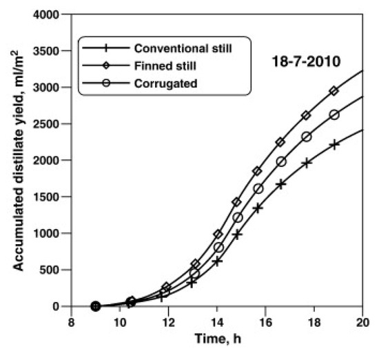
Figure 8.
The total distillate of the solar stills with finned and corrugated absorbers [31].
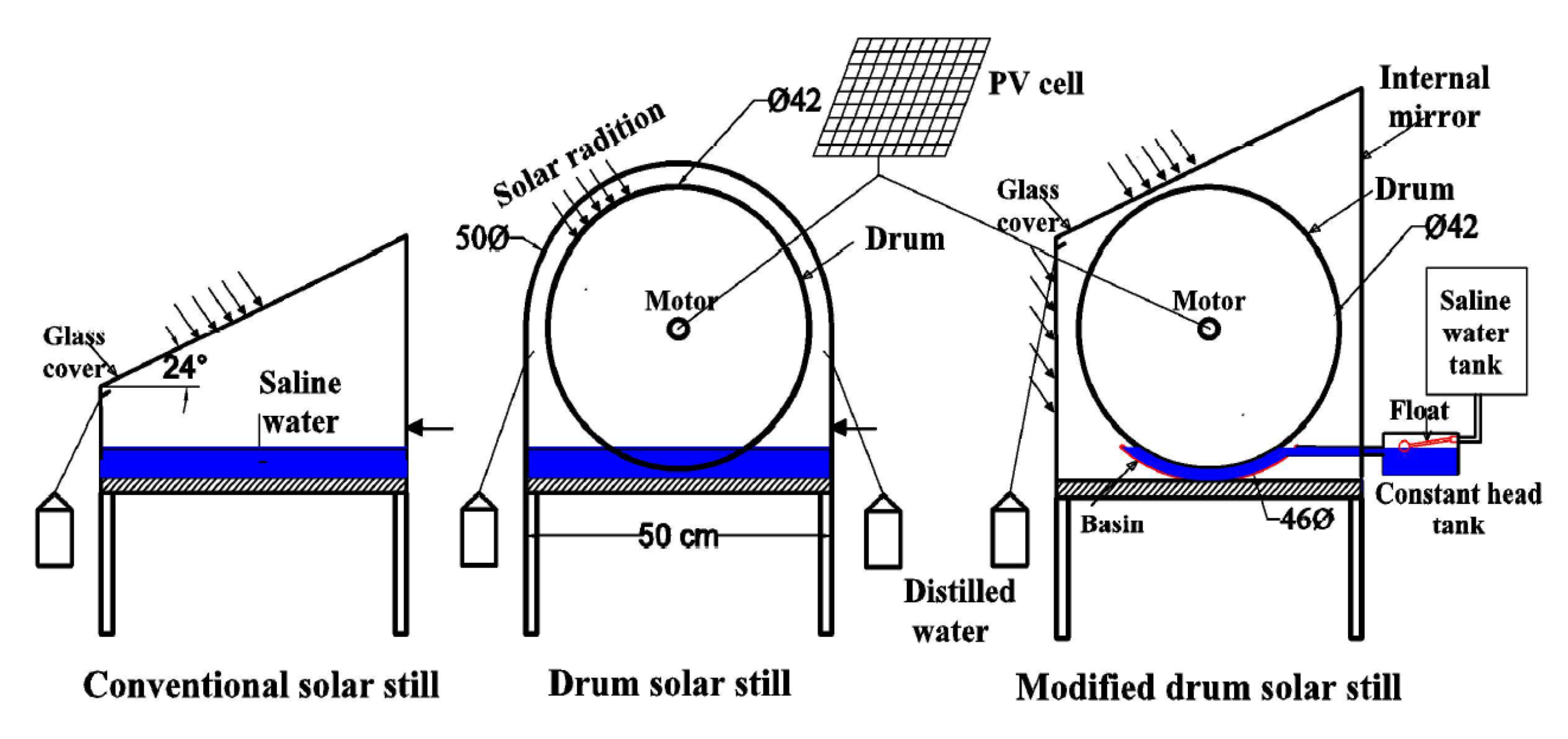
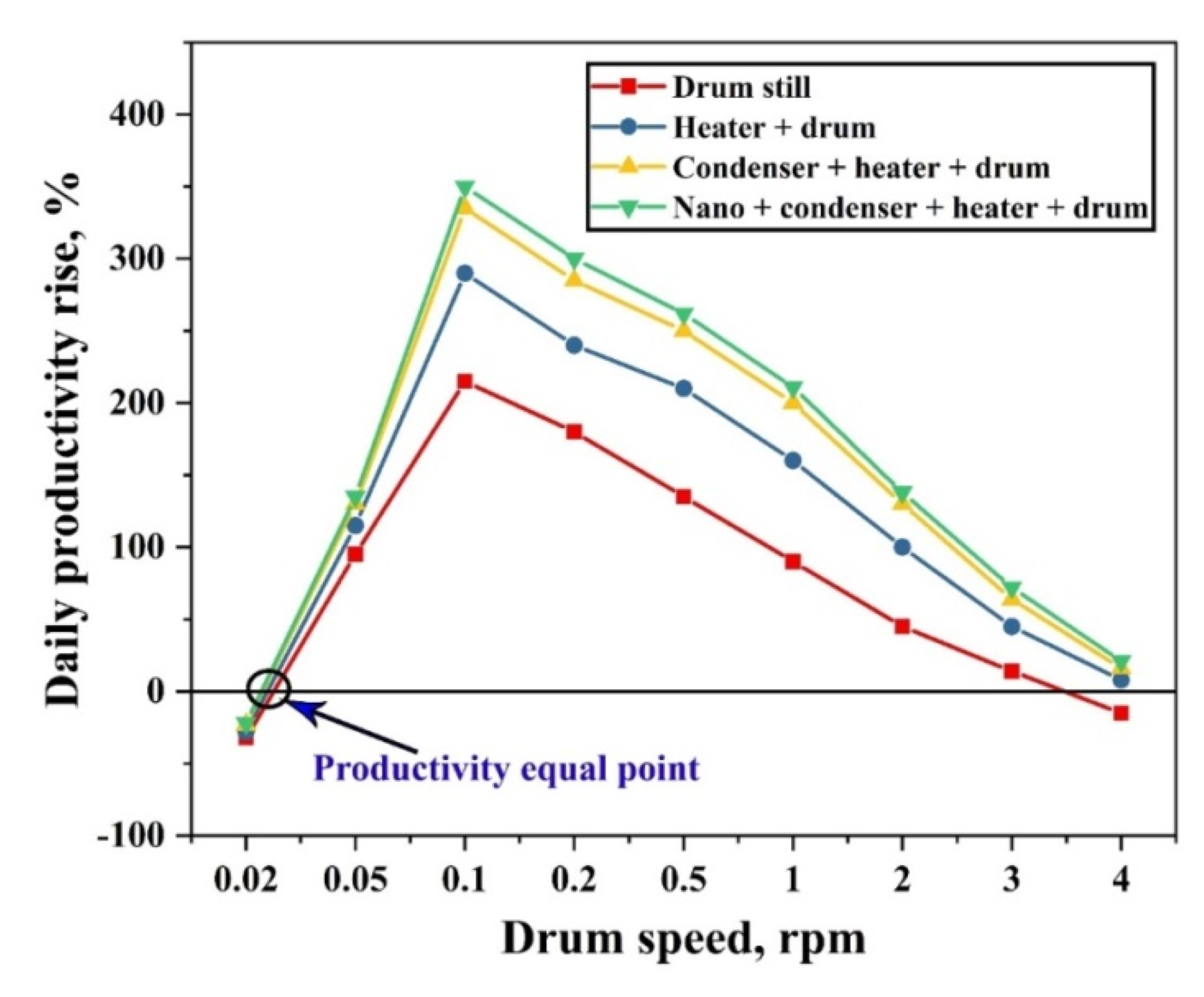
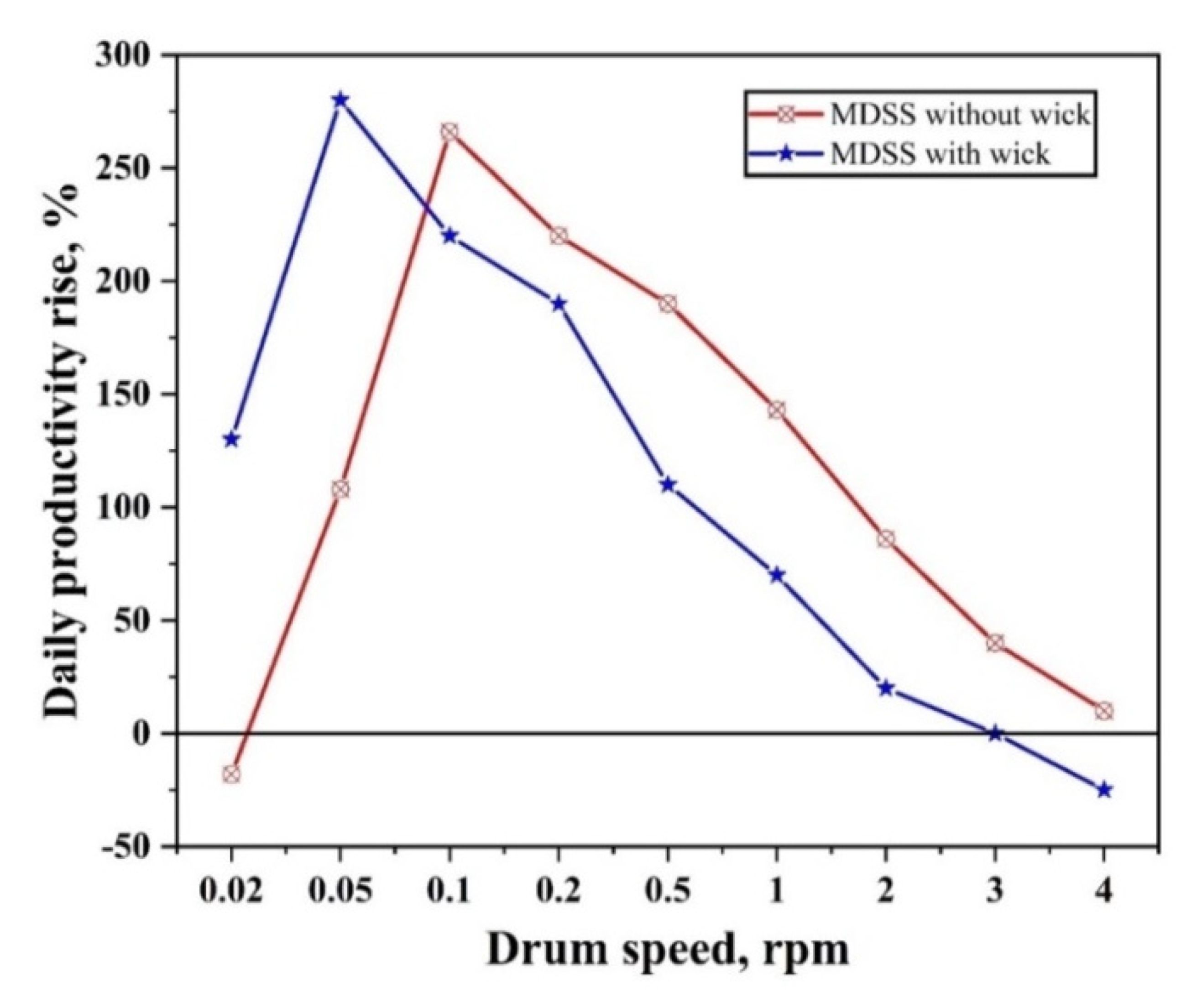
In addition, Abdullah et al. [5] examined experimentally and theoretically the influence of installing a rotating drum inside the solar still to increase the evaporative and exposure surface areas, Figure 9. The authors achieved an increase in the solar still yield by 350% and 296% under different operating conditions, as illustrated in Figure 10 and Figure 11.
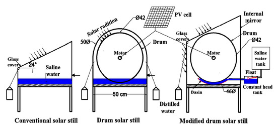
Figure 9.
Schematic of the experimental setup [32].
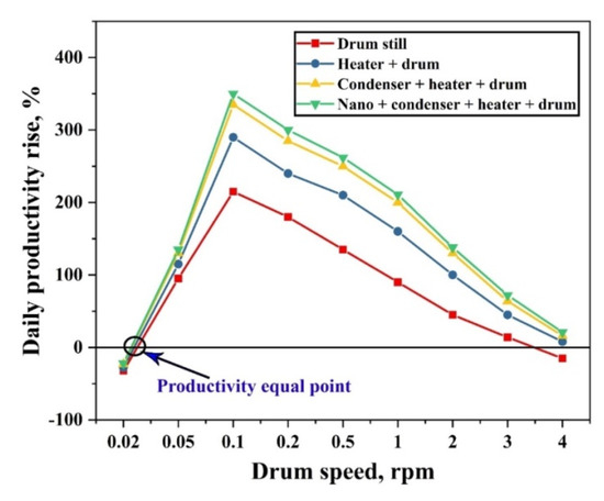
Figure 10.
The yield rise of the drum still at different drum rotational speeds [5].
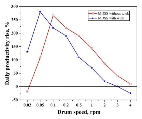
Figure 11.
The productivity improvement of the modified drum still with and without wick at different drum speeds [32].
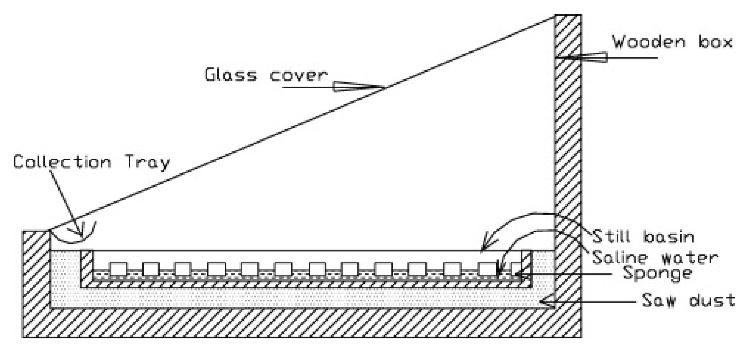
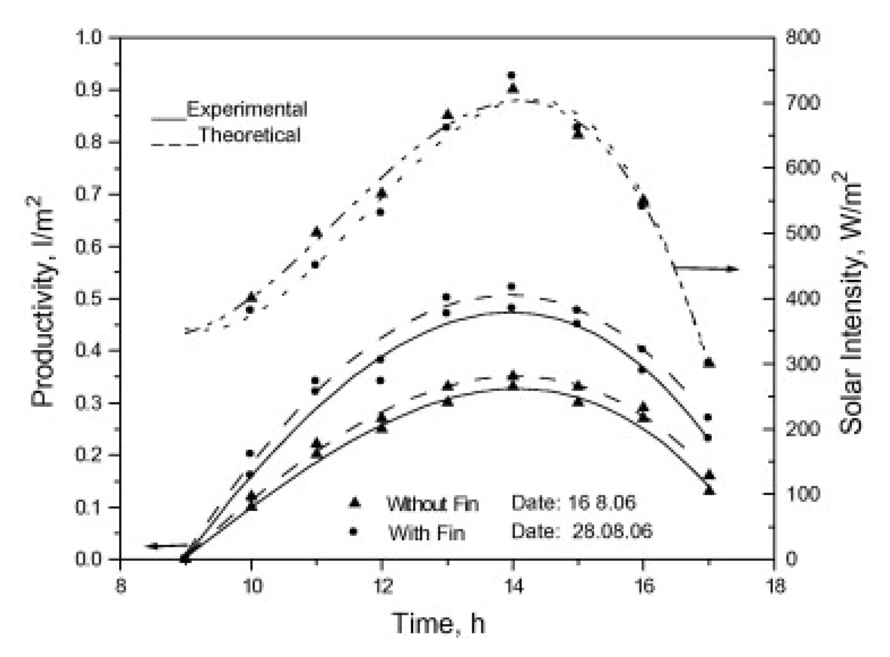
Velmurugan et al. [33] tested the effects of using fins and sponges on the performance of the solar still with and without wick, as shown in Figure 12. The authors concluded that the maximum increase in productivity was obtained when using fins, Figure 13. The solar still productivity was augmented by 15.3%, 29.6%, and 45.5% when using sponges, wick clothes, and fins, respectively.
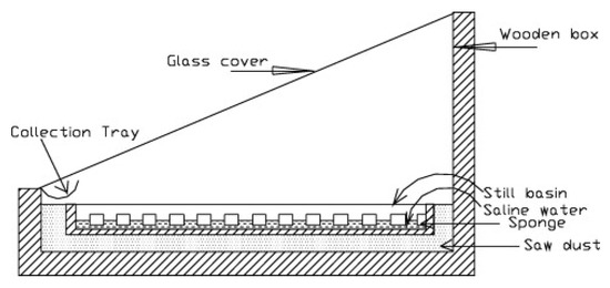
Figure 12.
Solar distiller with fins [33].
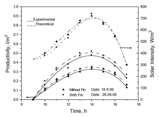
Figure 13.
Solar still yield when using fins [33].
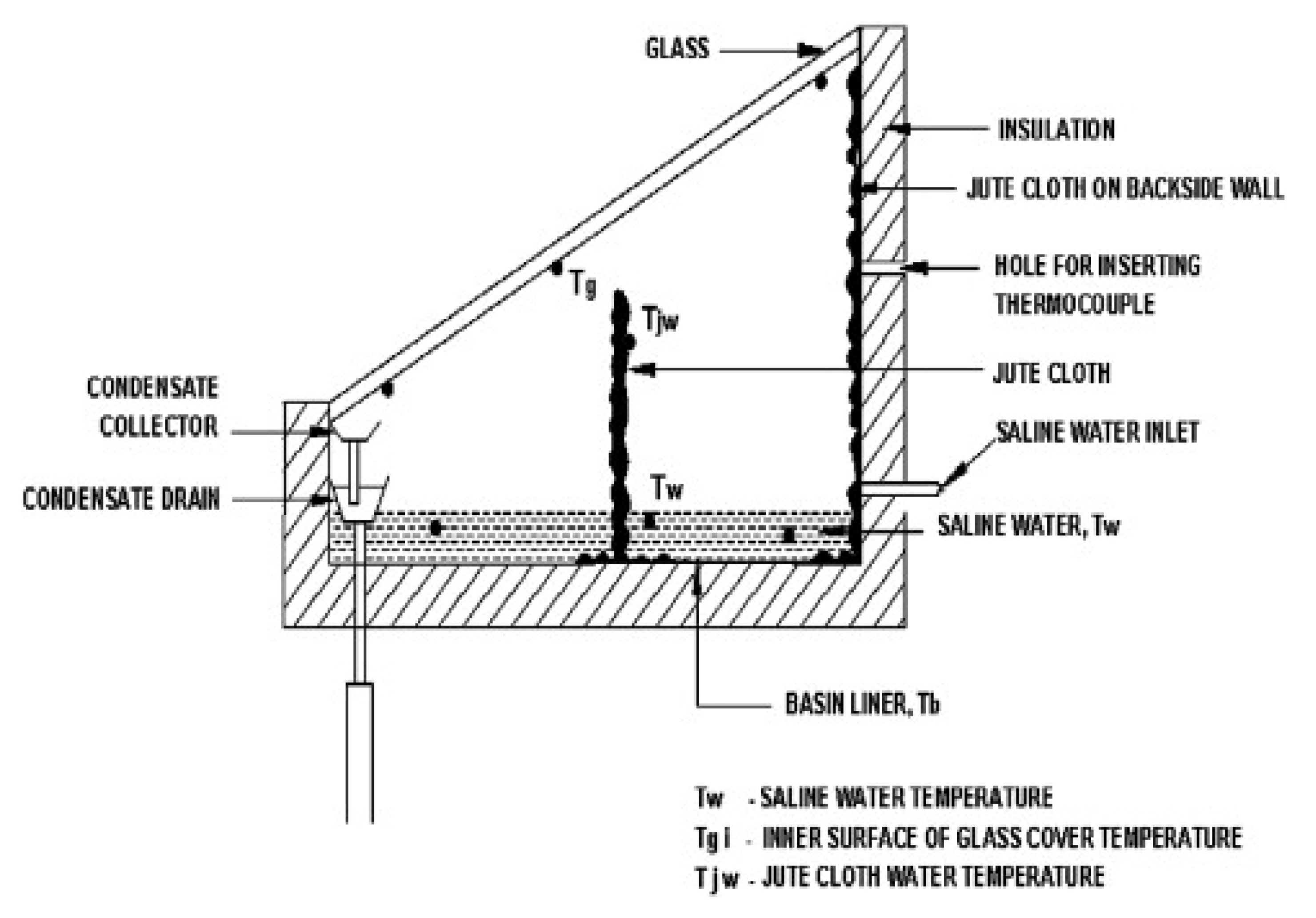
Sakthivel et al. [34] tried to raise the exposure surface area using the jute fabric material inside the basin, as shown in Figure 14. The authors reported that the solar still productivity and efficiency were enhanced by 20% and 8%, respectively. Moreover, Velmurugan et al. [35] stated that the solar distiller productivity could be augmented by 80% when using fins and sponges together.
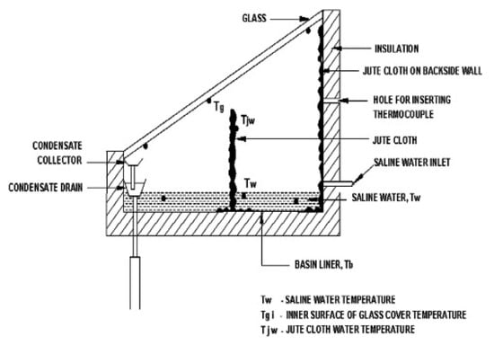
Figure 14.
Solar distiller with vertical jute material [34].
As it is explained above, using the wick raises the evaporative and exposure surface areas, and it can be used as an improvement modification for the solar still performance [36]. Moreover, using the wick material inside the solar still decreases the basin water depth as possible, and it uses the capillary property to replace the water that was evaporated with another saline water. Tiwari and Tiwari [37] stated that the lower the basin water depth, the higher the convective heat transfer rate, and the higher the freshwater productivity. Elango and Murugavel [38] tested the performance of double slope distiller and single slope distiller under different operating conditions. The authors stated that the optimum basin water depth is 1 cm, which produced the highest water productivity. In addition, Khalifa and Hamood [39] examined the performance of the solar still under various basin water depth. The authors revealed that the distiller yield could be increased by lowering the basin water depth.
4.2.2. Effect of Glazing Cover Material, Inclination, and Thickness
As is well known, the glass cover is the only port for the passage of the solar radiation to its destination which is the water. As a result, scholars are concerned with all properties of the glass that affect the performance of the solar distiller. These properties include the optical properties, thickness, and inclination of the glass cover. The main function of the glass in the solar distillation systems is allowing the solar radiation with high thermal energy to pass inside the solar distiller and block the longer wavelengths. This leads to making the distiller capture a maximum amount of solar radiation and does not permit to radiate this solar intensity back again. The outer side of the glass is exposed to the surrounding ambient conditions, which keep its temperature as low as possible. While the inner surface of the glass is in a direct contact with the created vapor in the distiller space above the basin saline water. This construction helps to make the inner surface of the glass into a condensing surface for the generated vapor because the glass has a temperature lower than that of the vapor [40]. Most publications report that the reliable thickness of the glass cover should be in the range of 3–4 mm. In addition, the thicknesses of glass from 3 mm to 6 mm were investigated by Ghoneyem and Ileri [41]. The authors found that the thickness of 3 mm provided greater evaporation and condensation rates compared with that of the other glass thicknesses.
On the other hand, the inclination angle of the glass cover plays a key role in the variations of thermal performance of the solar distillers. This is due to the following reasons:
The inclination angle of the glass cover determines its surface area, which strongly affects the heat transfer processes;
The inclination angle of the glass cover is the main reason for collecting the condensing distillate inside the solar distiller;
The glass cover inclination angle has a direct effect on the free motion and speed of the condensed droplets on the inner surface of the glass sheet. The bigger the glass inclination angle, the more speed of the condensed droplets. Moreover, the excessively small glass inclination angle leads to falling of the condensed droplets back to the basin again, which affects badly the performance of the solar distiller;
The inclination angle of the glass cover determines how much the solar distiller will receive direct and normal solar beams. As is well known, the more direct and normal solar beams received by the glass cover, the better performance of the solar distiller;
The sun declination angle affects the performance of the solar still in opposite directions: it has a negative effect during wintertime and a positive effect in summertime. Then, it is related directly to the inclination angle of the glass cover, which makes it a big challenge for the scholars to determine an optimum value for it throughout the year. This influences the amount of solar radiation reflected by the glass sheet as per the seasons. Thus, the solar distiller productivity would drop due to increase in reflected radiation because of increasing the tilt angle.
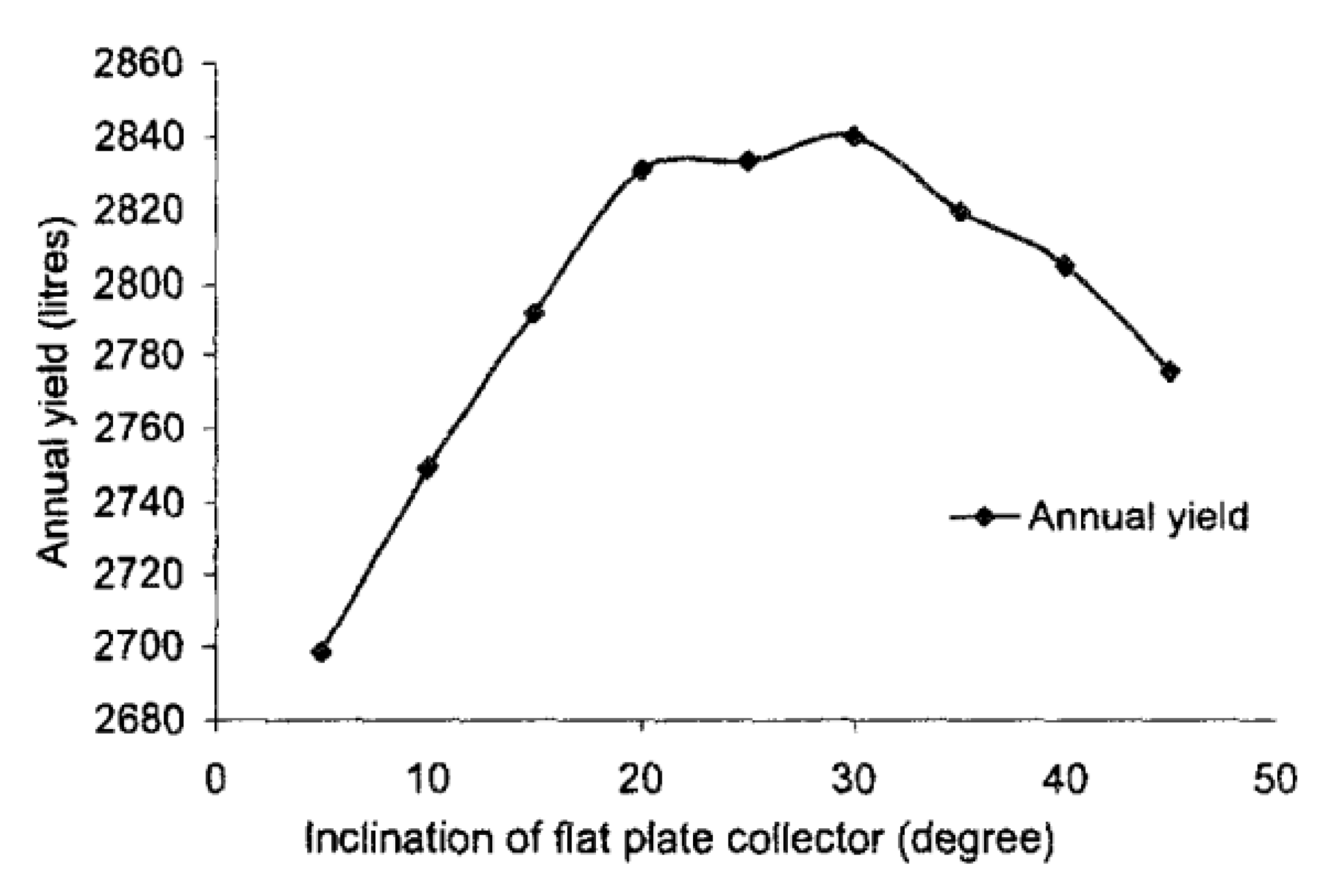
Akash et al. [42] tested the effect of changing the inclination angle of the glass cover. They used the angles of 15°, 25°, 35°, 45°, and 55° in their test-rig. The authors reported that the best inclination angle was 35°, which produced the maximum distillate for the solar distiller investigated in May in Jordan. That angle (35°) is almost equal to the latitude of that place (31°). Moreover, Singh and Tiwari [43] confirmed that the distillate of the distiller would be optimized when the glass inclination angle is equal to the latitude of the place of experiments, as shown in Figure 15.
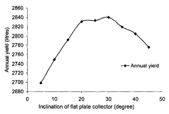
Figure 15.
Annual productivity of the active solar distiller with various collector tilts [43].
In addition, Velmurugan et al. [33] affirmed the conclusion that the glass inclination angle should equal the value of latitude of the place of experimentations to ensure better performance of the solar stills. To prove that, the authors conducted two experiments in Madurai on a single basin solar distiller with tilt angles of 10° and 9.55°. Moreover, Panchal and Shah [44] carried out experiments on a solar still with a tilt angle of 30°, which was the same angle of latitude of Mehsana, Gujarat where the experiments were conducted. The authors reported superior efficiency at that glass inclination angle. There are numerous publications confirming that the productivity of the solar distiller would be maximum at a tilt angle equals to the Latitude of the place of experimentations [43,45,46,47]. Another study stated that the thermal efficiency of the solar distiller would be superior if the glass tilt angle equals ±10 of the latitude of the place of experimentations. As a result, Al-hassan and Algarni [48] conducted an experimental tests on the performance of pyramid solar distiller with a tilt angle of 45° in Syria where the latitude is 35°, and they provided good productivities of solar stills.
Furthermore, Fath et al. [49] recommended the application of single-slope solar still for places with a latitude greater than 20° for obtaining superior productivities. Additionally, Murugavel et al. [50] affirmed the same conclusion. This recommendation come from the fact that if the double slope distiller is applied at the places with a latitude of more than 20°, only one side of the distiller would be exposed to the solar radiation and the opposite side would have a shadow. This will lead to more losses from the glass and affect badly the solar distiller performance.
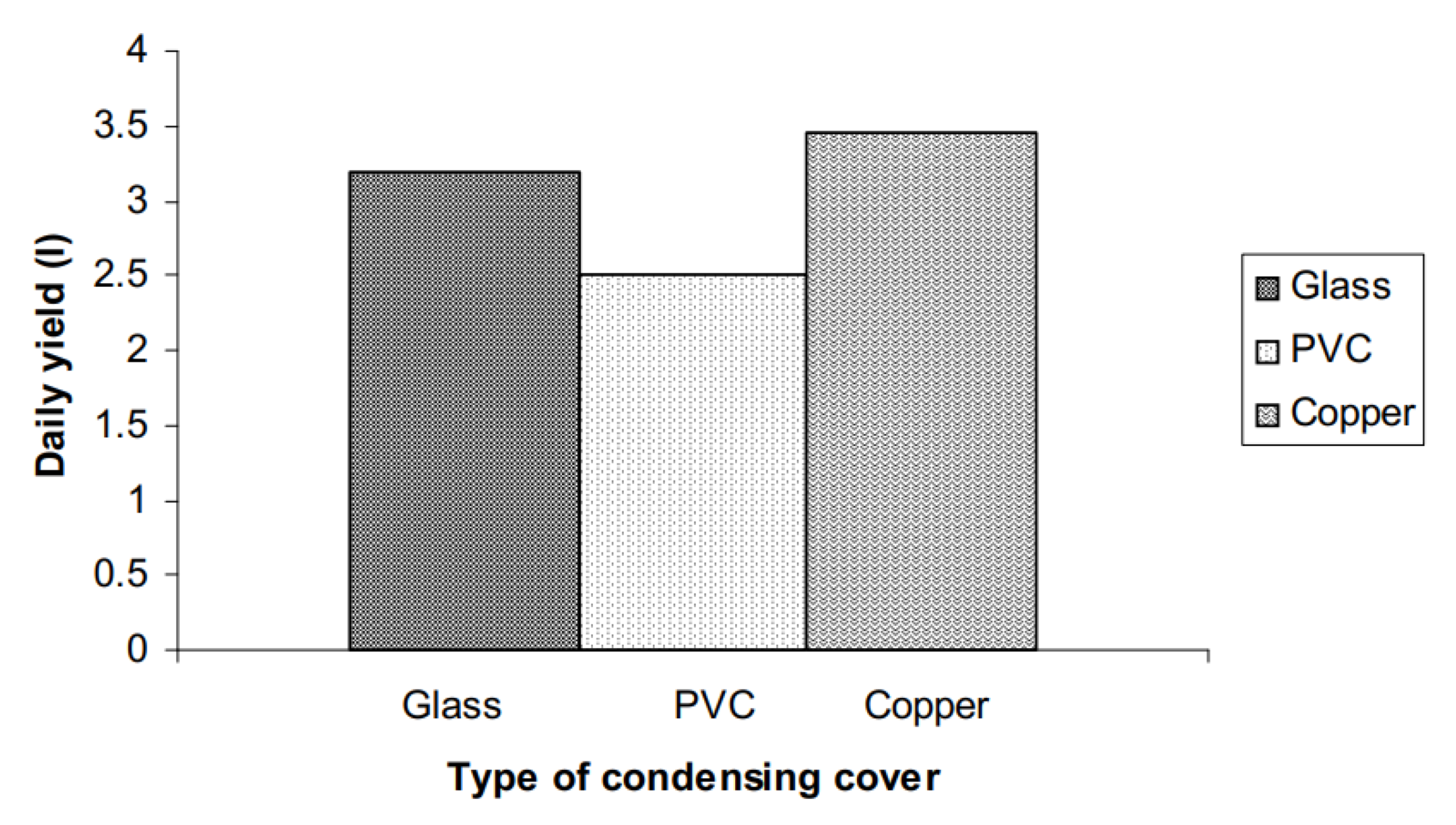
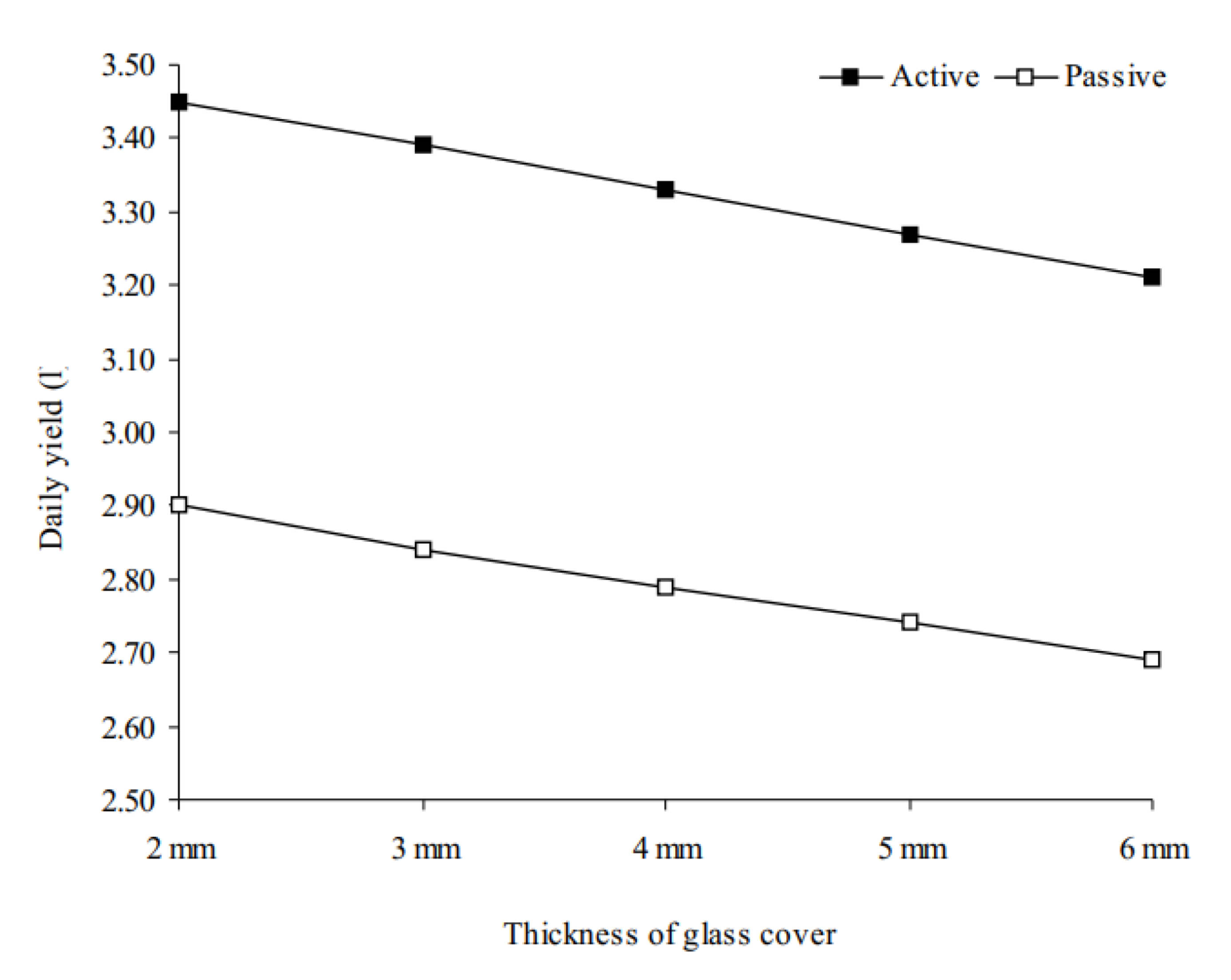
Furthermore, one of the factors that strongly affect the performance of the solar distillers is the type of the glass cover material. This is because the type of the material of glass defines the optical properties of the glass cover, and hence it affects the quantity of the absorbed solar radiation. As a result, the scholars used different types of glass in an attempt to specify the best kind of glass materials that are recommended to be used as a cover for the solar distillers. Consequently, the fabrics, nylon panels, metal sheets, glass sheets were utilized. Tiwari et al. [51] tested the effect of using glass, copper, and PVC materials as a cover for the solar distiller. Additionally, the authors tested the effect of changing the glass thickness on the distillate of the distiller. Their results revealed that the best material to work as a cover for the active solar distiller was the copper material compared to that of the glass and PVC materials, where the productivity reached 3.5, 3, and 2.5 L/m2.day, respectively, as shown in Figure 16. The copper provided greater yield due to its highest thermal conductivity which improves the heat transfer properties. In addition, their study concluded that the distillate productivity of the solar still would drop with increasing the glass cover thickness as shown in Figure 17. Whereas, the glass cover was the best choice for the passive solar still.
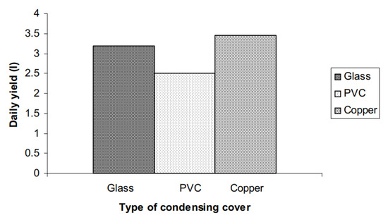
Figure 16.
The daily productivity of the active solar distiller under three different types of cover material [51].
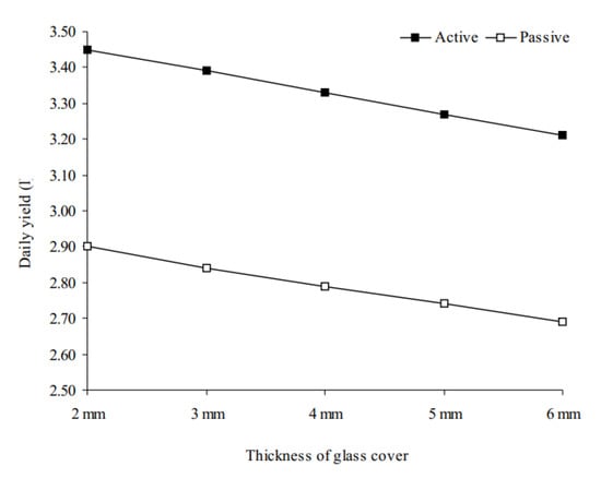
Figure 17.
The daily productivity of the solar distiller under different thicknesses of the glass cover [51].
Moreover, Martin and Goswami [52] investigated the influence of using the covers of aluminum, copper, and steel sheets on the performance of an active solar still. The authors reported that the copper sheet provided better performance of active solar distiller as compared with that of the aluminum and steel sheets. Additionally, the aluminum sheet obtained higher productivity than that of the steel sheet. Yet the cost of the copper and aluminum sheets is almost the double of that of the galvanized steel, and therefore, they are eliminated in the use of covering [53]. Whereas, the glass cover is the best choice for the passive solar stills.
4.2.3. Effect of Solar Still Materials
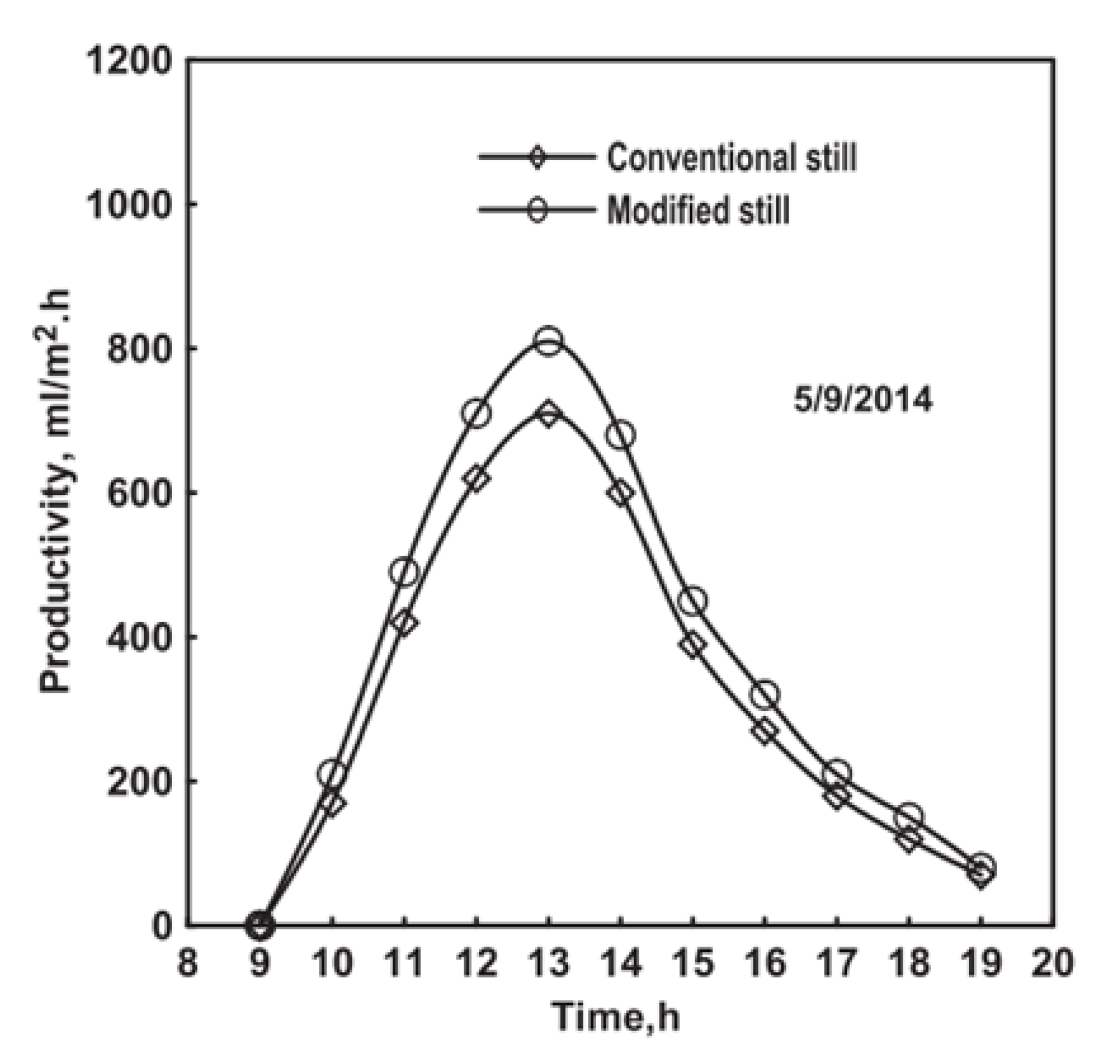
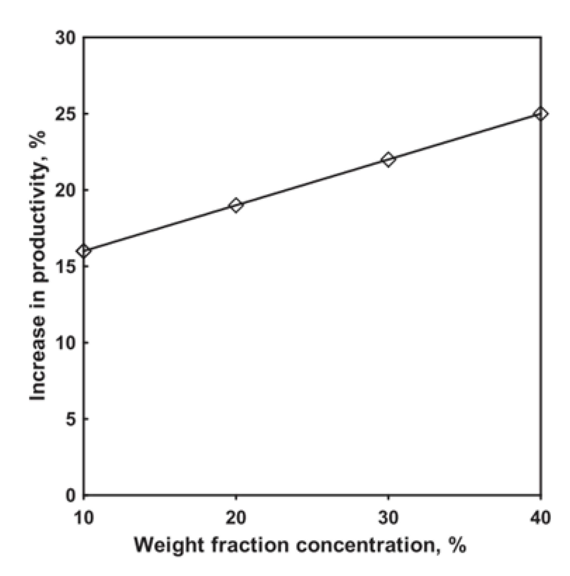
As is well known, the solar still performance is a function of the convective and evaporative heat transfer coefficients. As a result, the material and color of the basin body are of importance to state the performance of the distiller. For instance, Kabeel et al. [54] painted the solar still walls and bottom from the inside and outside with black paint mixed with CuO nanoparticles. The proposed system enhanced the working mechanism of the heat transfer and improved the freshwater productivity of the modified solar distiller compared to that of the conventional distiller as shown in Figure 18. Additionally, they tested the effect of using different concentrations of the nanomaterials in the black paint liquid, and they found that increasing the CuO nanoparticles weight concentration up to 40% raised the daily productivity by 25%, as shown in Figure 19.
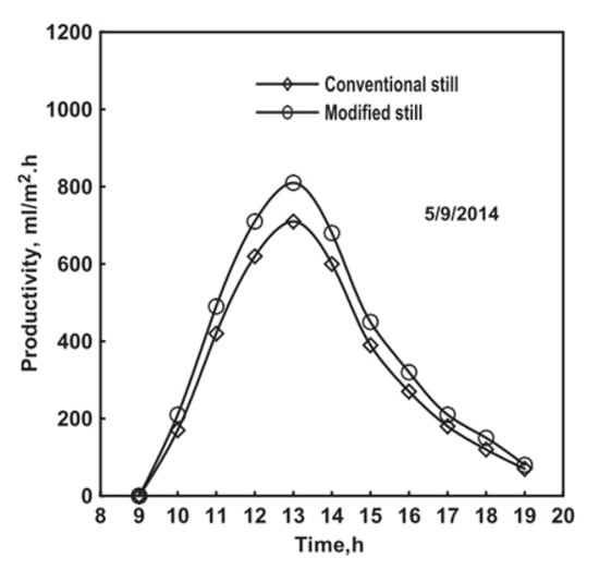
Figure 18.
Effect of painting the distiller walls and bottom by the black color mixed with CuO nanoparticles [54].
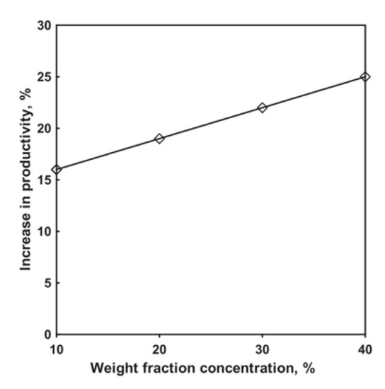
Figure 19.
Effect of CuO nanoparticles concentration on the daily productivity rise of the modified distiller [54].
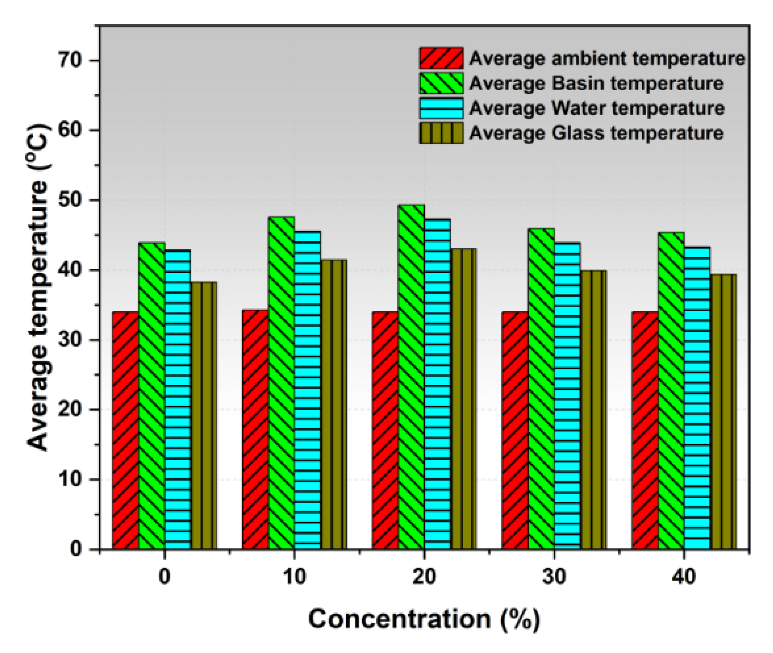
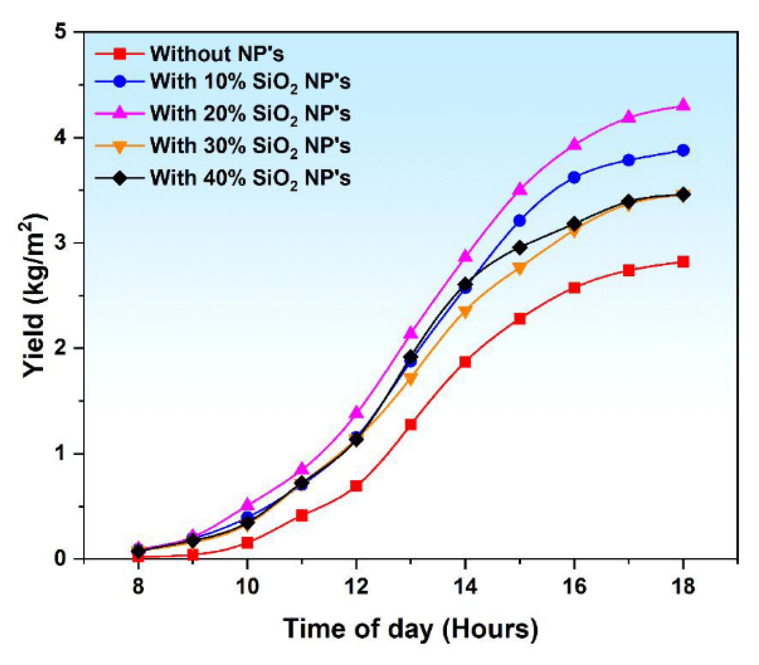
Moreover, Kabeel et al. [55] painted the basin liner of a pyramid solar distiller by TiO2 nanomaterials doped in black paint to improve the absorbing and heat transfer characteristics of the absorber under different water depths (1–3.5 cm). The authors affirmed that using the nanoparticles to paint the absorber increased the basin water by 1.5 °C than that without nanomaterials. In addition, the experimental results revealed that the water productivity of the distiller was improved by 12% as a result of using the TiO2 nanomaterials in the black paint of the absorber. Furthermore, Sathyamurthy et al. [56] tested the effect of using fumed silicon oxide nanomaterial mixed with black color liquid to paint the absorber of stepped solar distiller. The results showed that the basin water temperature is sensible to the paint and nanoparticle concentration of the absorber, as illustrated in Figure 20. Additionally, they obtained that the optimum nanoparticles concentration was 20% as obtained in Figure 21. Morepver, the authors obtained an increase in the distillate of the stepped solar distiller by 34.29% at a weight fraction of the nanoparticles by 20%.
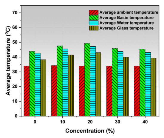
Figure 20.
Effect of nanoparticles concentration on the average basin water temperature [56].
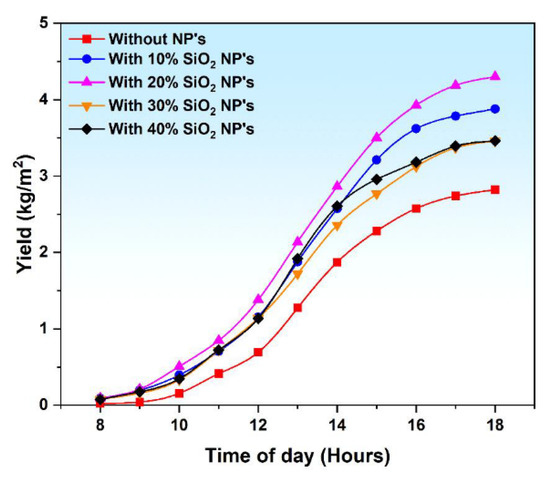
Figure 21.
Effect of nanoparticles concentration on the distillate of the stepped distiller [56].
4.2.4. Effect of Solar Still Volumetric Isometry
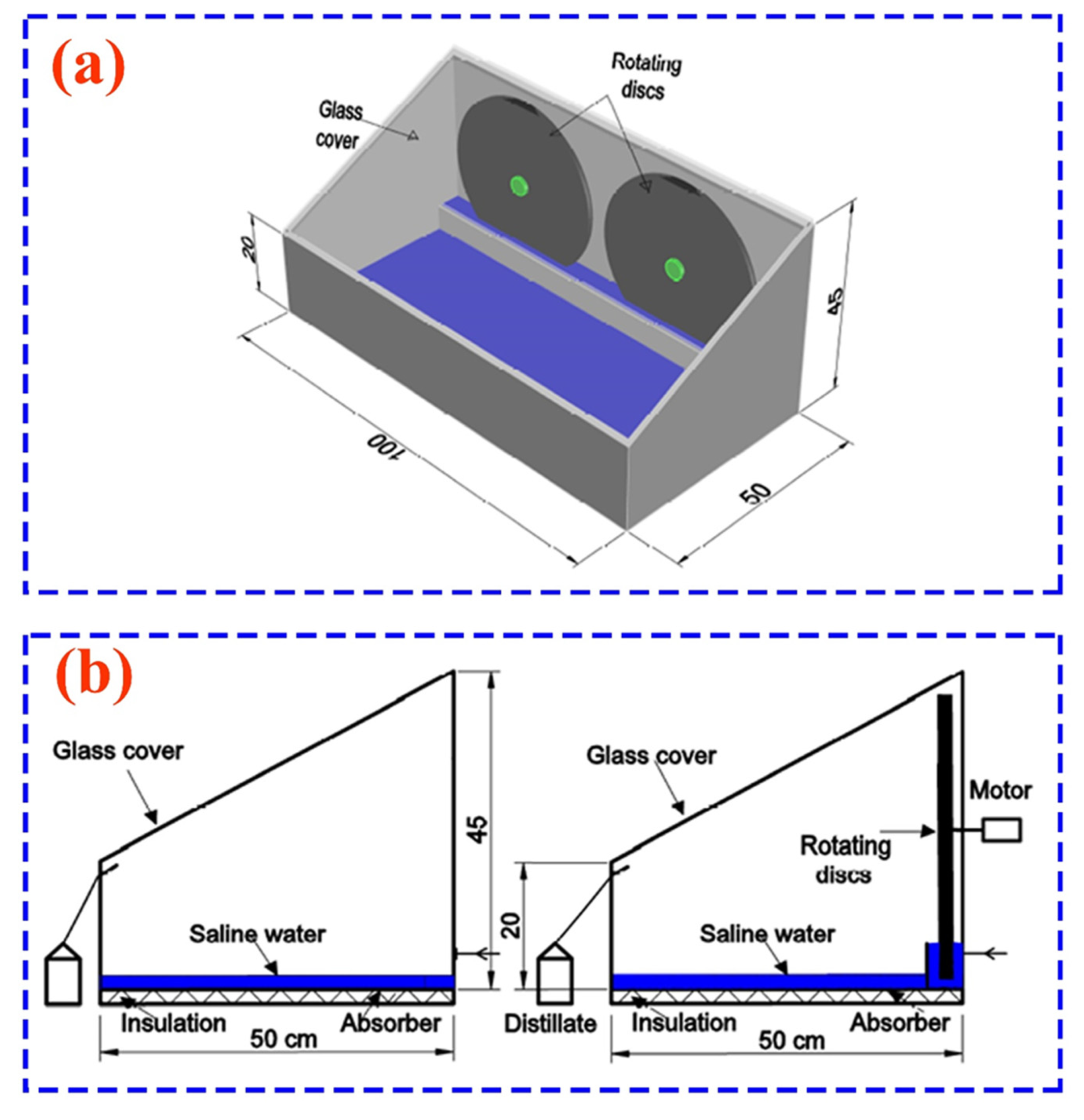
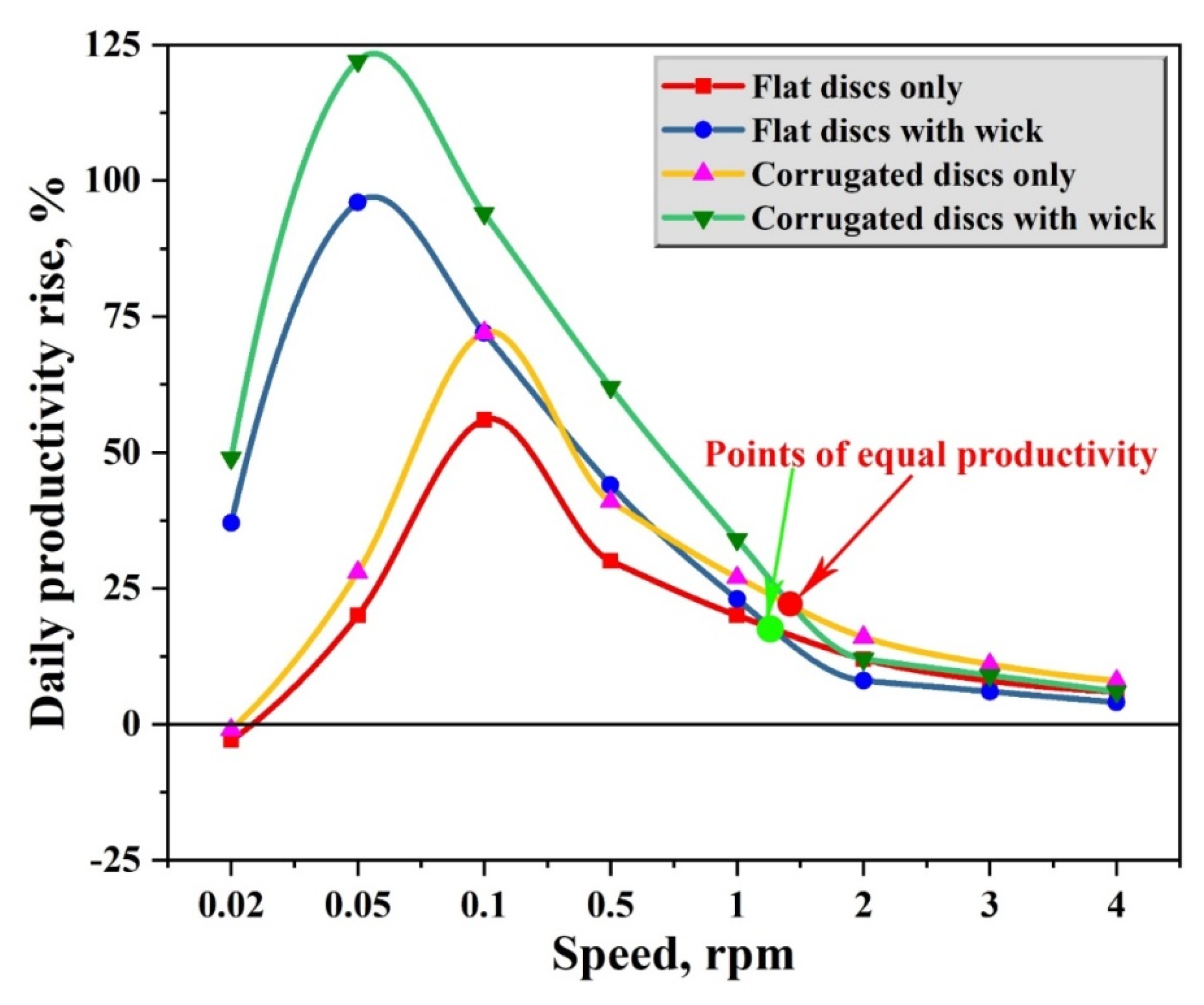
For the first time, this point is considered as a factor that affects the performance of the solar still because has recently been investigated. The external shape of the solar still has a great effect on its thermal performance. As well, the internal design and the space between the basin water surface and the internal glazing surface have also a vital role on the freshwater productivity of the distiller. Recently, Essa et al. [21] introduced the new desalination mechanism of rotating disc solar distillers as illustrated in Figure 22. The authors fixed two rotating discs inside the solar still and tested the effect of the rotating speed of those discs. Additionally, they examined the effect of the disc shape (flat and corrugated discs) with and without wick on the performance of the distiller. The results revealed that the best conditions that obtained the highest productivity were using the corrugated disc with wick at the speed of 0.05 rpm, as observed in Figure 23. At these conditions, the productivity was augmented by 124% as compared to that of the conventional distiller.
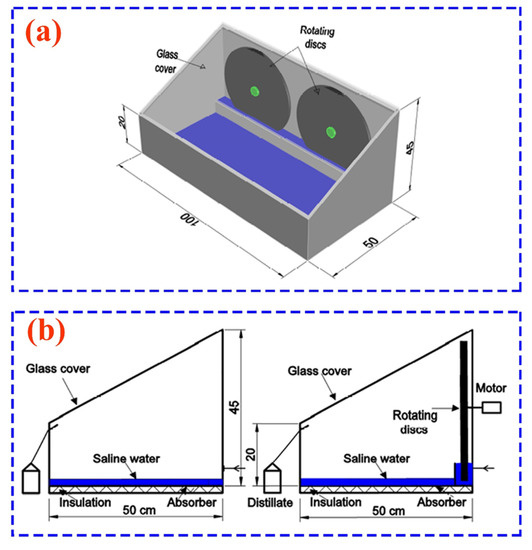
Figure 22.
Schematic of the rotating disc solar still: (a) isometry of disc solar still and (b) schematic of both conventional and disc solar stills [21].
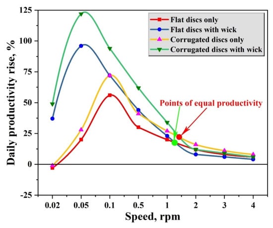
Figure 23.
Effect of disc speed and shape on the productivity of solar still [21].
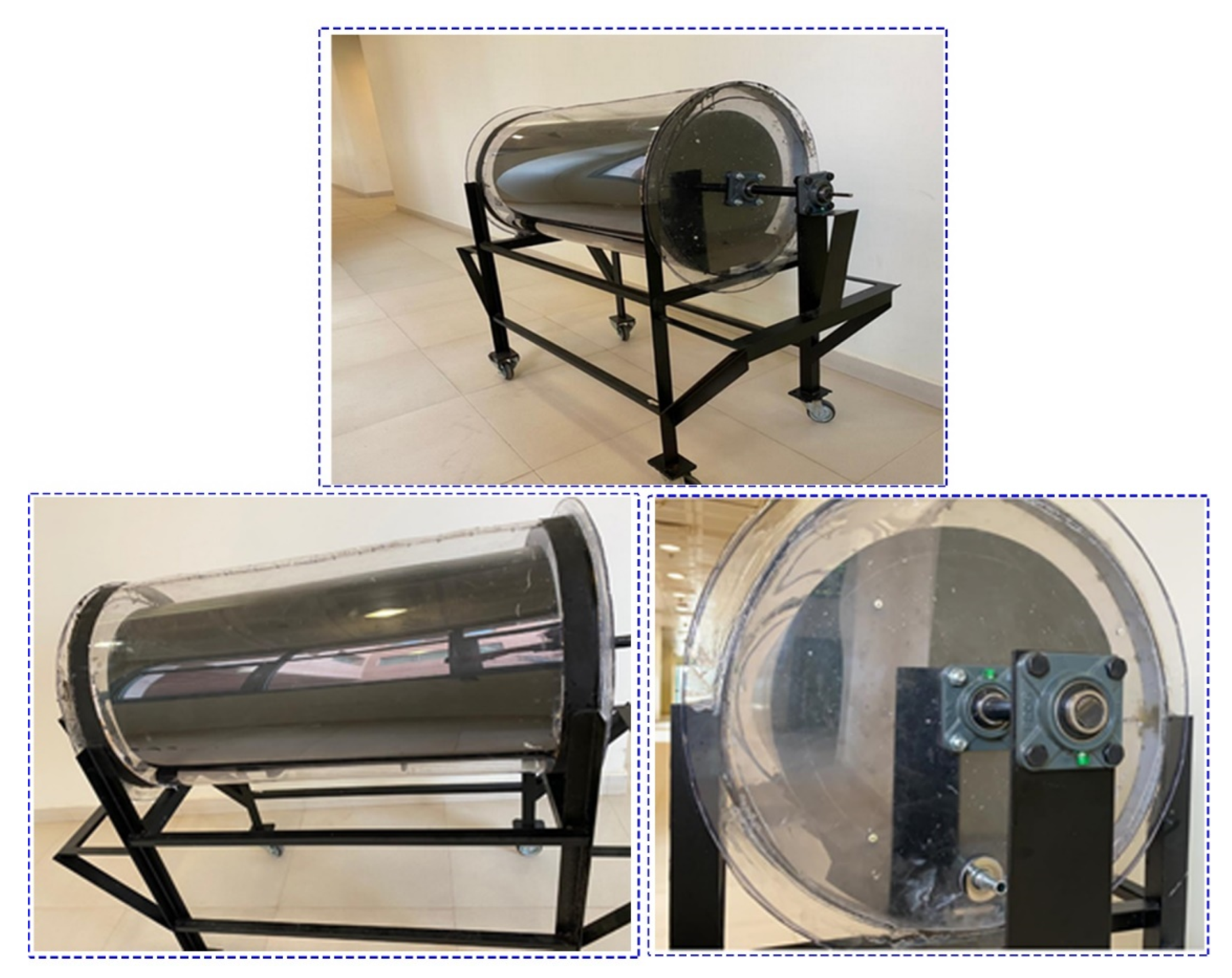
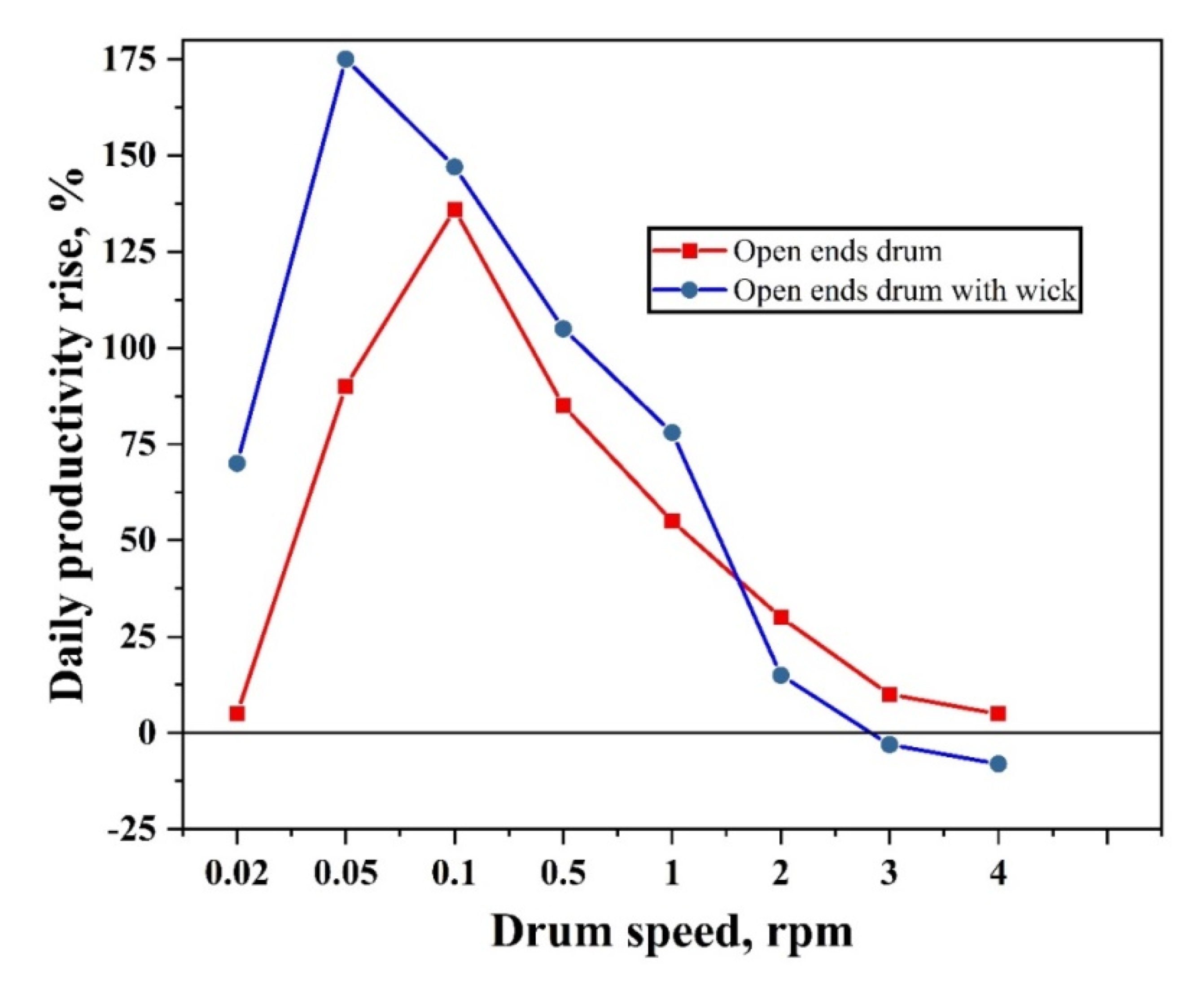
Moreover, Essa et al. [57] conducted a comprehensive experimental and theoretical study on a tubular solar still with rotating cylinder with and without wick, as shown in Figure 24. This design made the space between the water surface and glazing smaller as possible; hence the evaporation and condensation rates were better. Additionally, the authors tested the effect of drum rotating speed (0.02–4.0 rpm) and type of drum (closed ends drum and open ends drum) on the distiller performance. The authors reached an increase in the daily productivity by 175% at 0.05 rpm with wick and open cylinder, Figure 25.
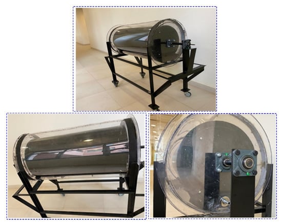
Figure 24.
Photo of tubular solar distiller with rotating cylinder [57].
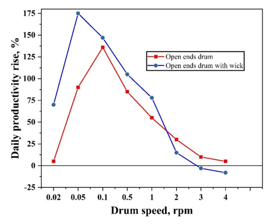
Figure 25.
Daily distillate increase under different speeds with and without wick [57].
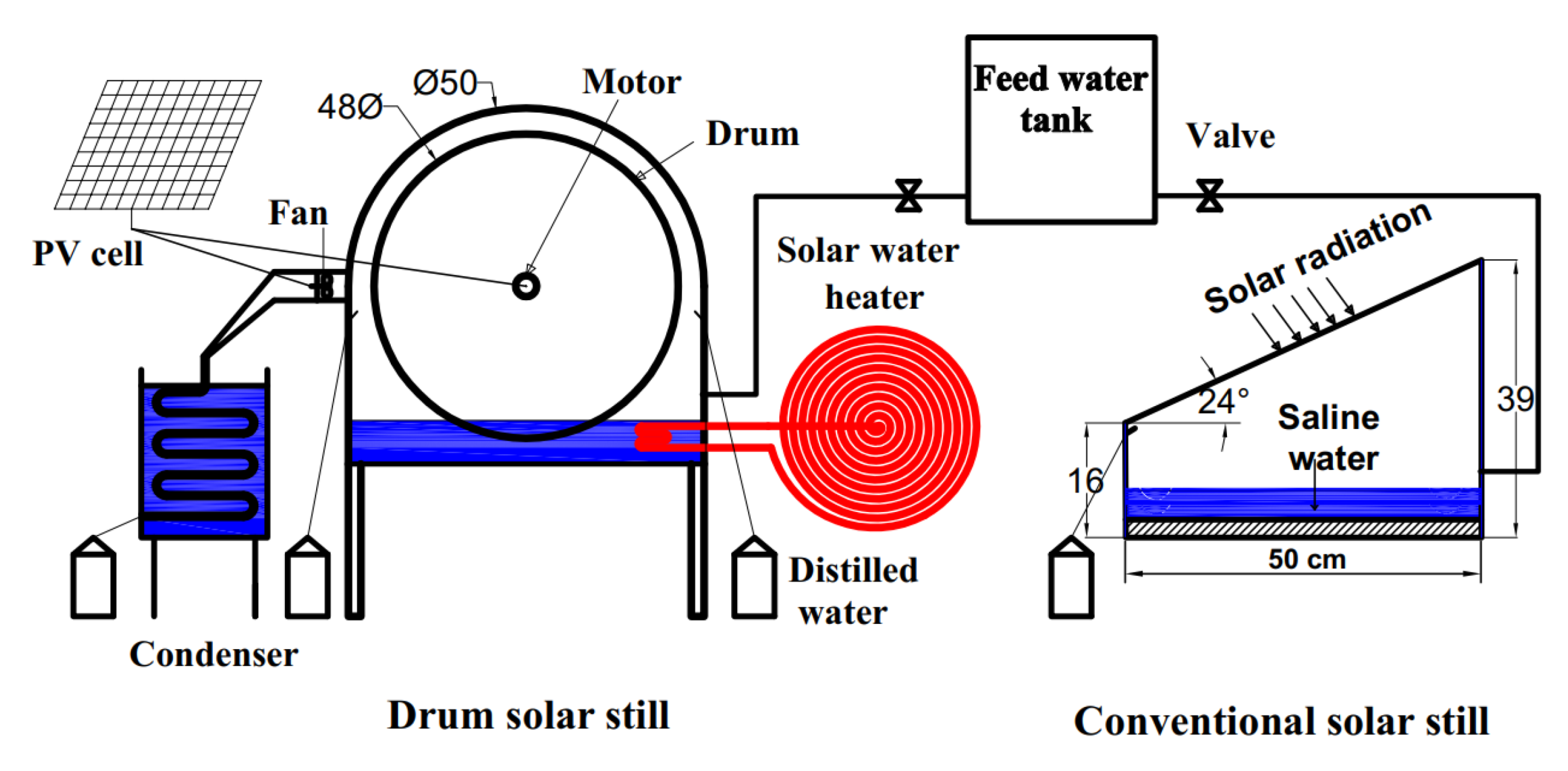
Furthermore, Abdullah et al. [5] proposed a rotating drum inside the conventional solar still with solar water heater and external condenser, Figure 26. These modifications improved the solar still productivity by 350%.
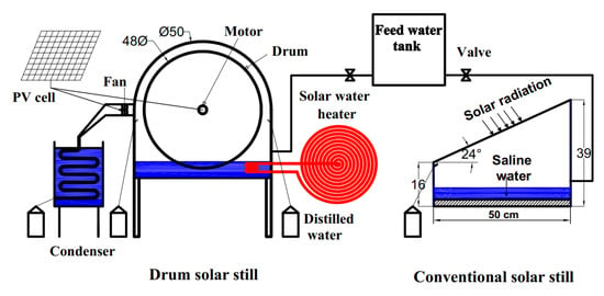
Figure 26.
Schematic of the drum distiller with the heater and condenser [5].
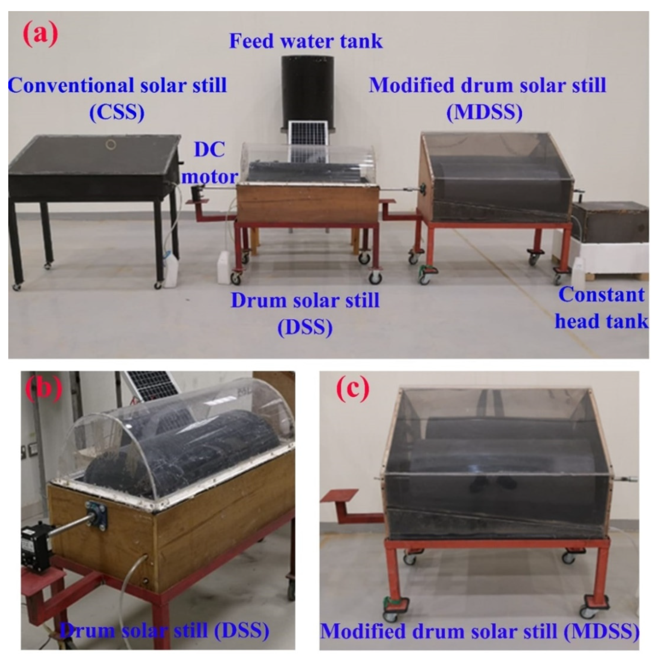
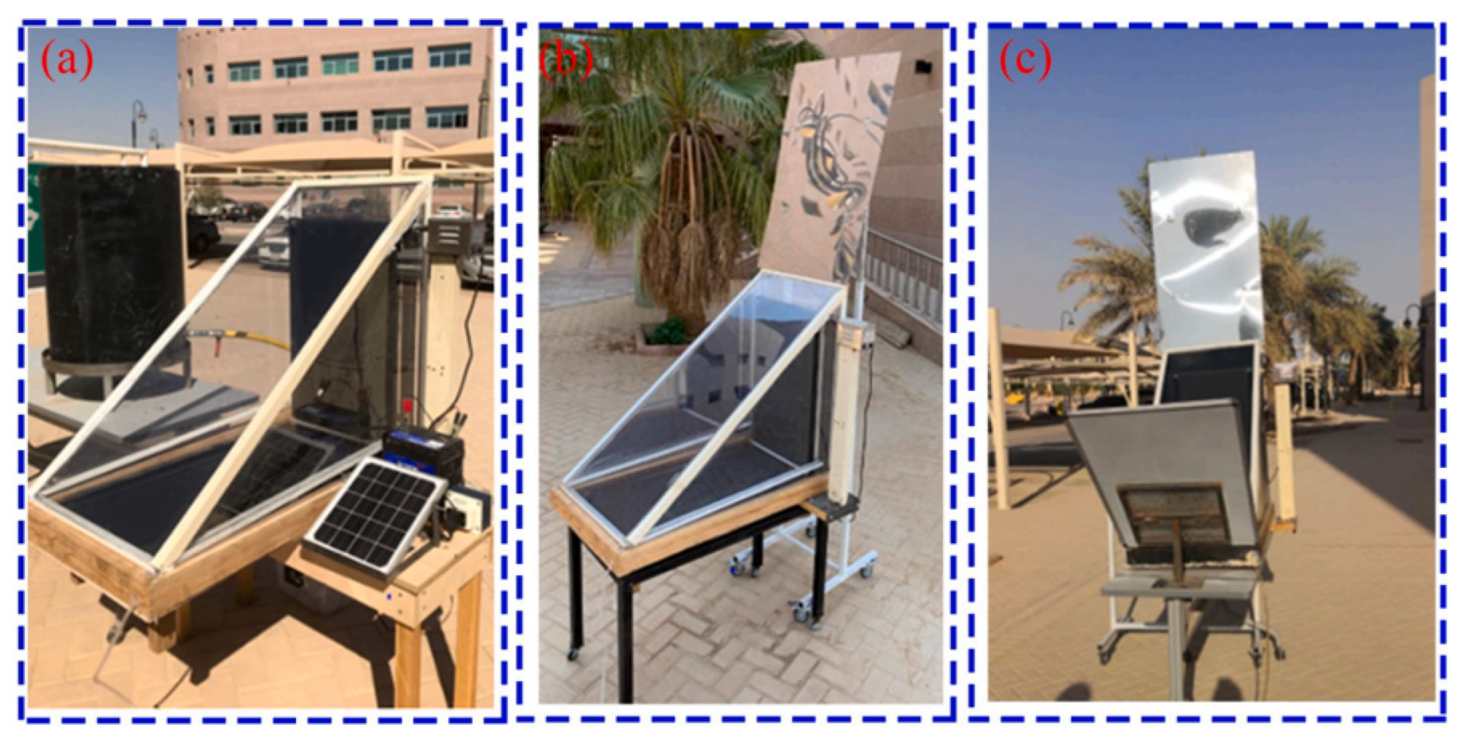
After that, Abdullah et al. [32] used the rotating drum inside the solar still with curved and flat glazing cover as illustrated in Figure 27. Furthermore, they tested the effect of using reflectors, CuO–water nanofluid, and wick material on the performance of the modified drum solar distiller. Results obtained that the freshwater distillate was improved by 296% over that of the conventional distiller.
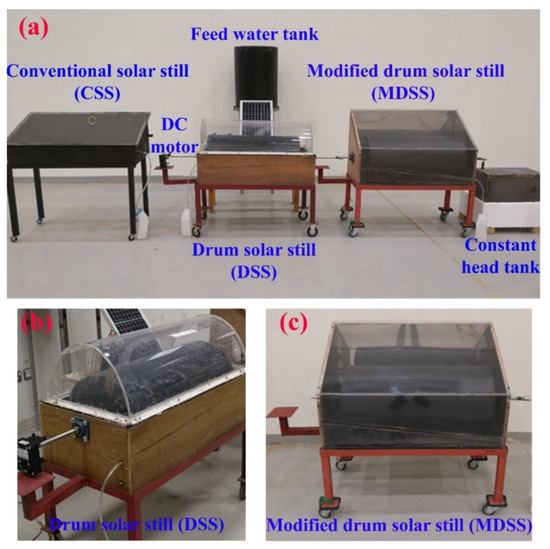
Figure 27.
Photo of the conventional and modified drum solar stills: (a) total experimental setup, (b) drum solar still, and (c) modified drum solar still [32].
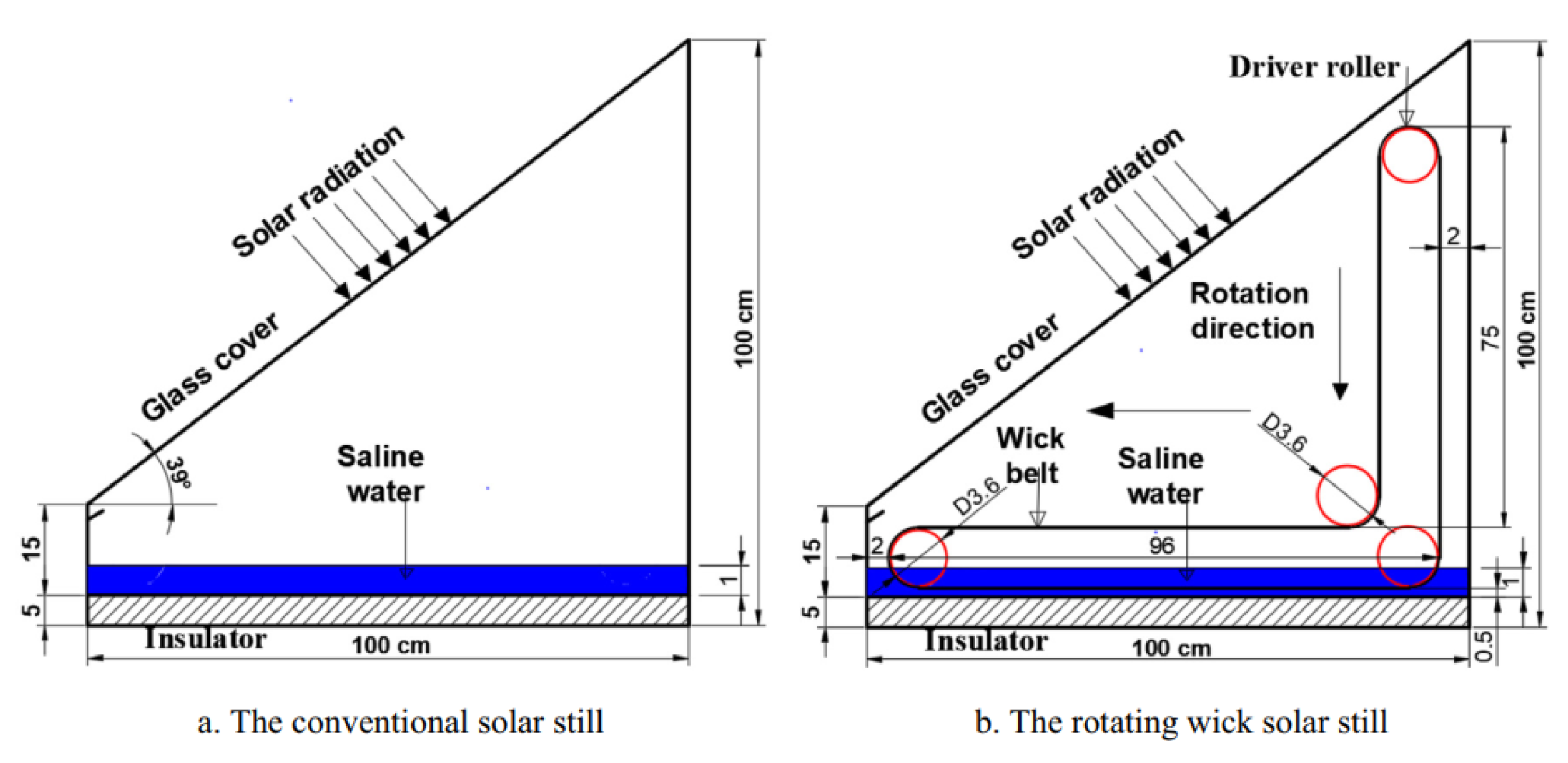
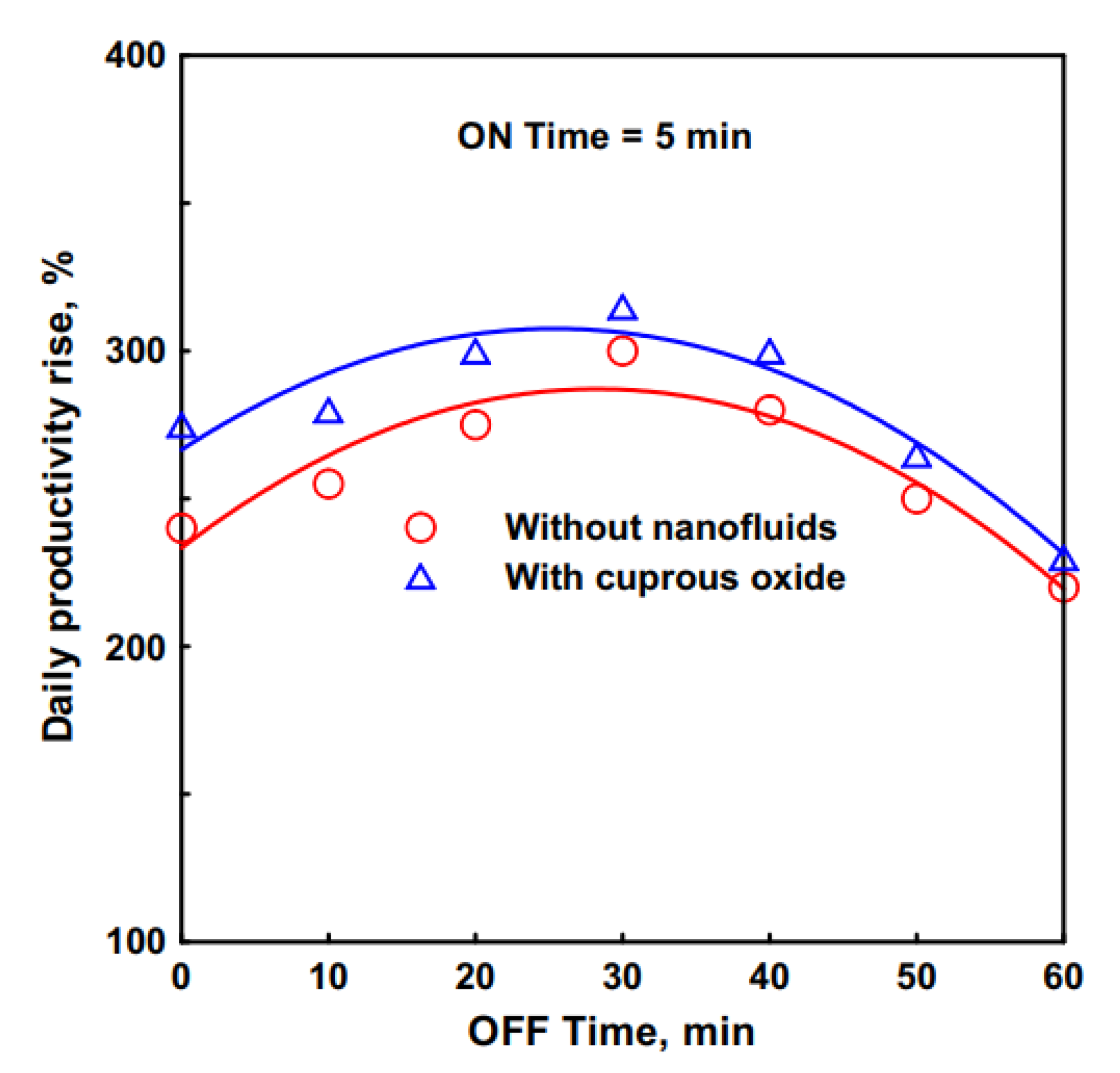
In addition, Abdullah [58] installed a black jute cloth belt inside the solar distiller to be rotated horizontally and vertically as shown in Figure 28. The belt was rotated for 5 min and turned off for various OFF times (zero, 10, 20, 30, 40, 50, and 60 min). Results obtained that the OFF time 30 min provided superior performance as compared to the other cases or that of the conventional distiller. The productivity of the modified rotating wick distiller was improved by 315% over that of the traditional distiller as shown in Figure 29. Additionally, the thermal efficiency reached 84%.
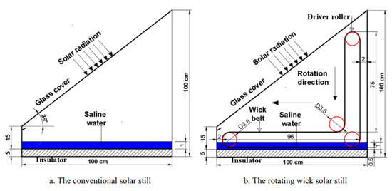
Figure 28.
Schematic of the conventional and rotating wick solar distillers [58].
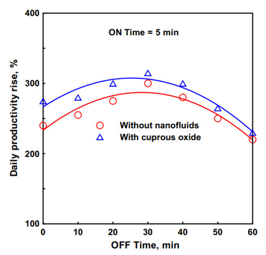
Figure 29.
Effect of the OFF times on the daily distillate rise of the rotating wick distiller with and without nanomaterial [58].
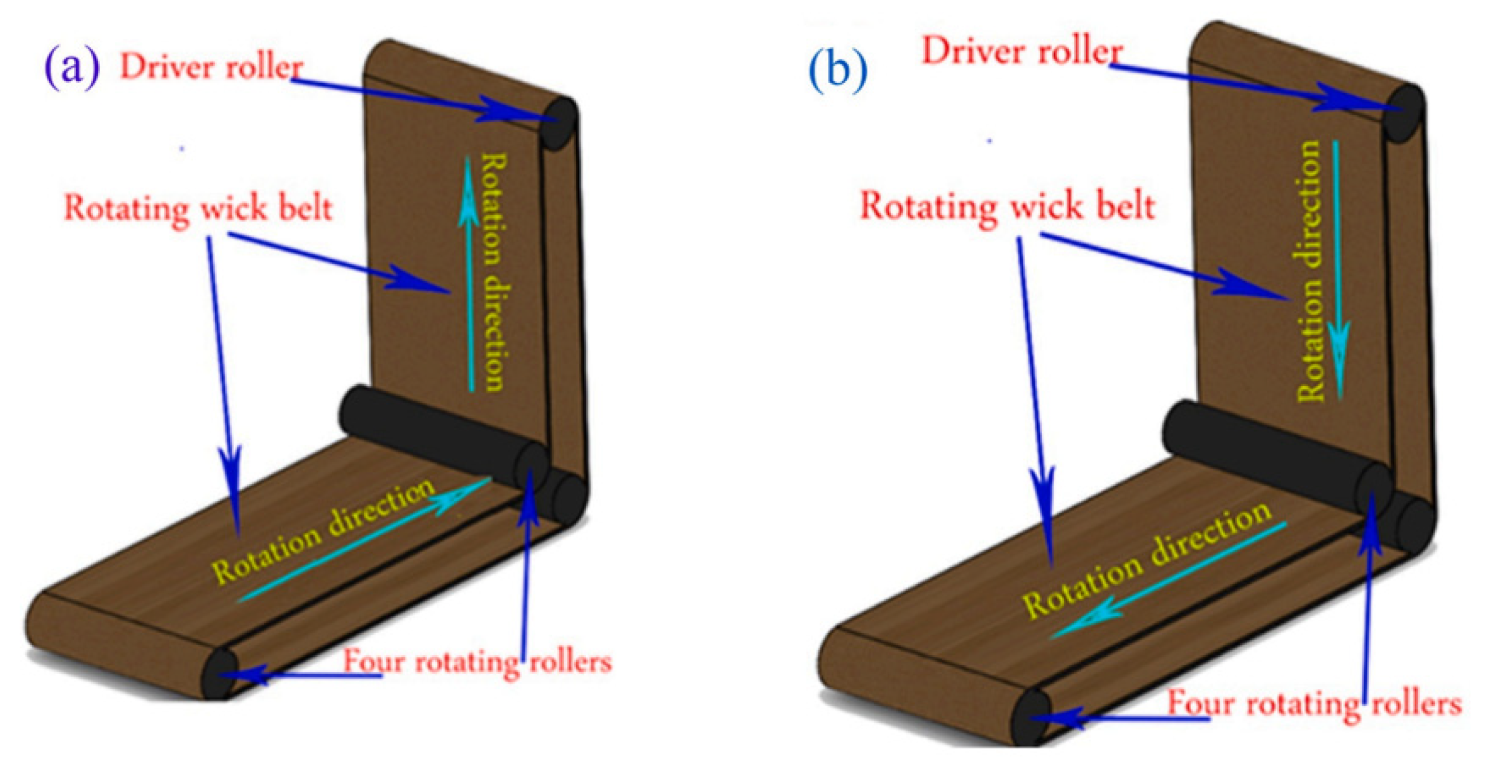
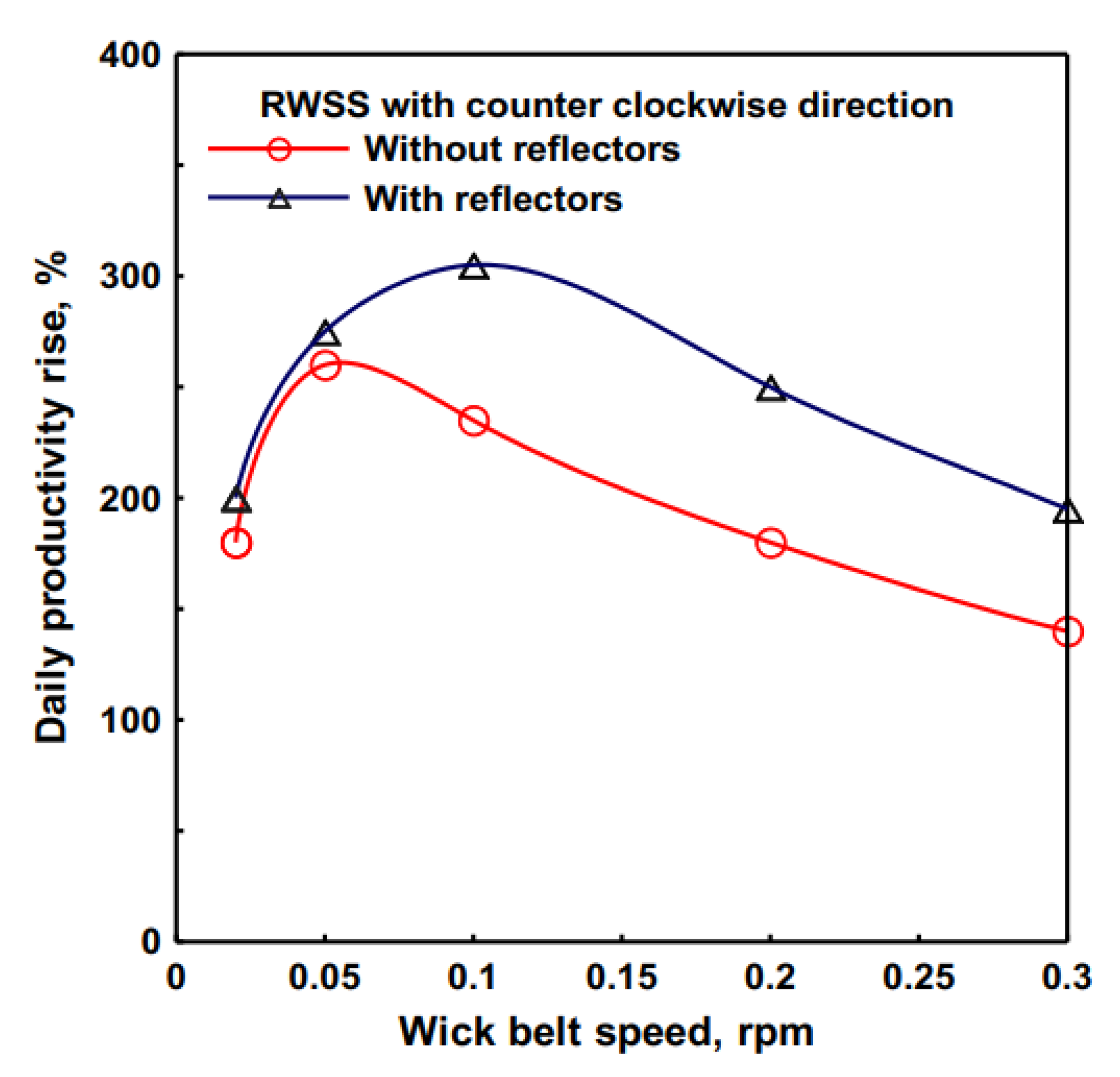
Whereas, in another study, Abdullah et al. [59] changed the design of the rotating wick belt and tested the effect of rotation direction and using reflectors on the performance of the rotating wick distiller as shown in Figure 30 and Figure 31. Additionally, the authors tested the impact of different rotating speeds of the wick belt. The highest performance of the distiller (without reflectors) was obtained at 0.05 min−1, where the distillate was augmented by 260%. Whereas, using reflectors increased the productivity by 300% at 0.1 min−1, Figure 32.
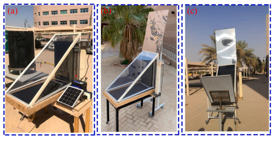
Figure 30.
Rotating wick distiller (a) without reflectors, (b) with internal and top reflectors, and (c) with top and bottom reflectors [59].
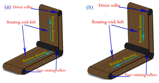
Figure 31.
Rotation direction of the wick belt: (a) Counterclockwise and (b) clockwise [59].
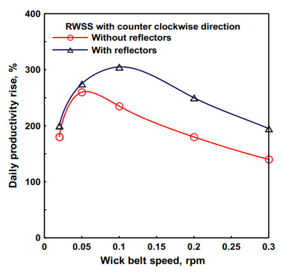
Figure 32.
Effect of belt speeds and reflector on the daily distillate rise of the rotating wick distiller [59].
Abdullah et al. [60] designed a trays solar still shown in Figure 33 to occupy the space inside the distiller in increasing the evaporative and exposure surface areas. Moreover, the authors used reflectors and paraffin wax mixed with CuO nanoparticles as a phase change material. The trays distiller productivity was enhanced by 108% due to the synergetic effect of the reflectors and paraffin wax/CuO PCM.
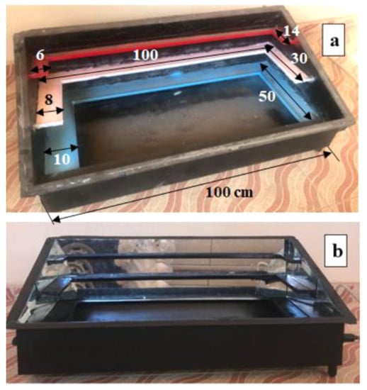
Figure 33.
Trays solar still (a) without mirrors and (b) with mirrors [60].
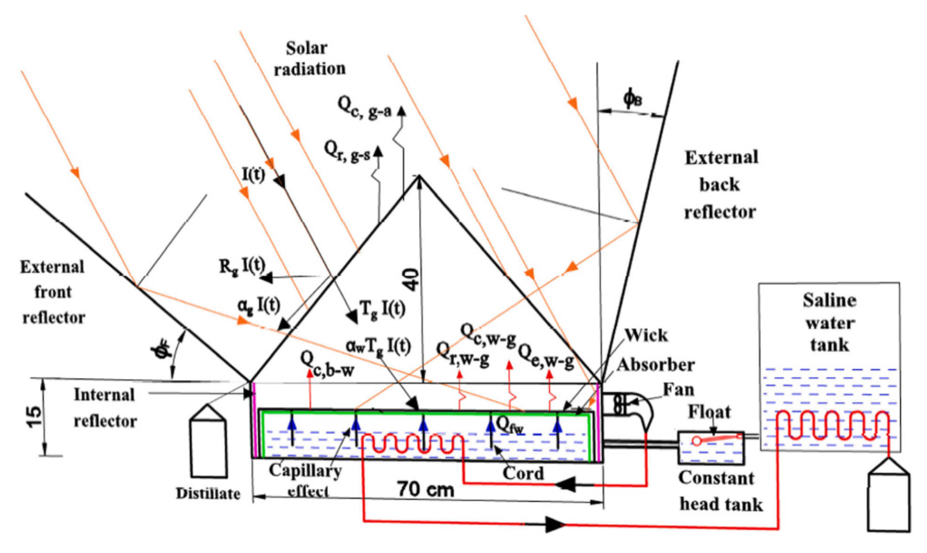
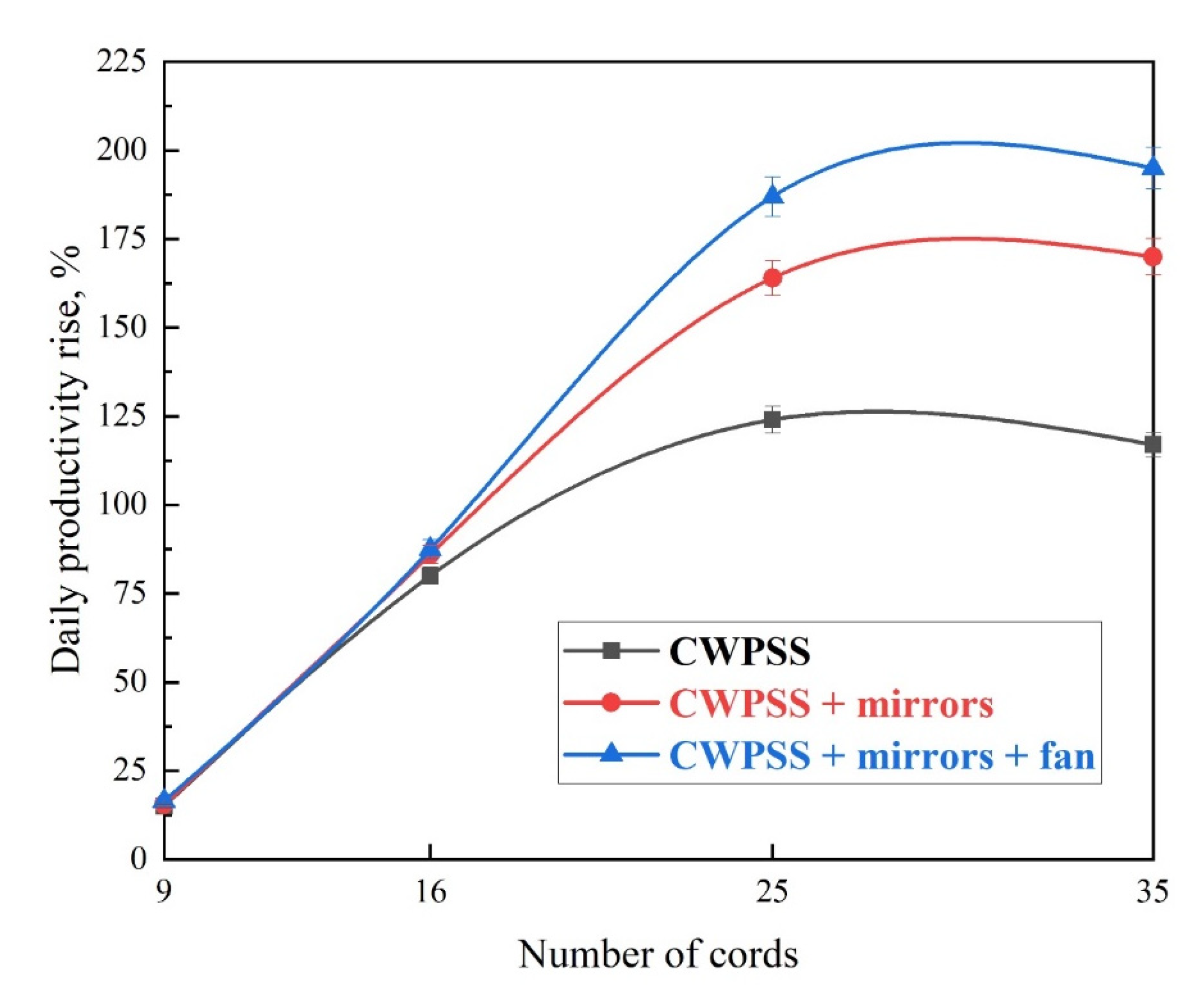
Moreover, Essa et al. [61] proposed a pyramid distiller with wick cords, external and internal mirrors, and internal and external cooling cycle, as illustrated in Figure 34. The effect of various numbers of wick cords (9, 16, 25, and 35 cords) were studied. It was reported that the highest performance of distiller was achieved when utilizing the reflectors and cooling with 35 wick cords, as shown in Figure 35. At these conditions, the efficiency was 53% and the distillate improvement was 195% over the traditional still.
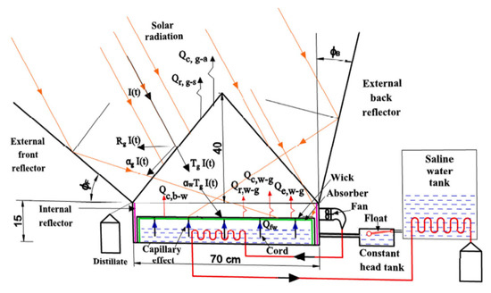
Figure 34.
Schematic of the cords wick pyramid distiller with wick cords, external and internal mirrors, and internal and external cooling cycle [61].
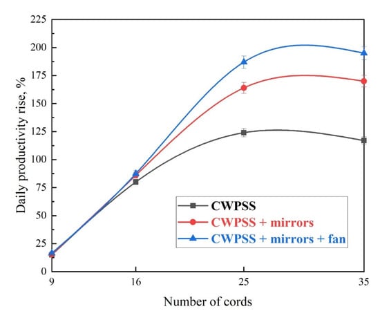
Figure 35.
Impact of cords number on the daily distillate rise [61].
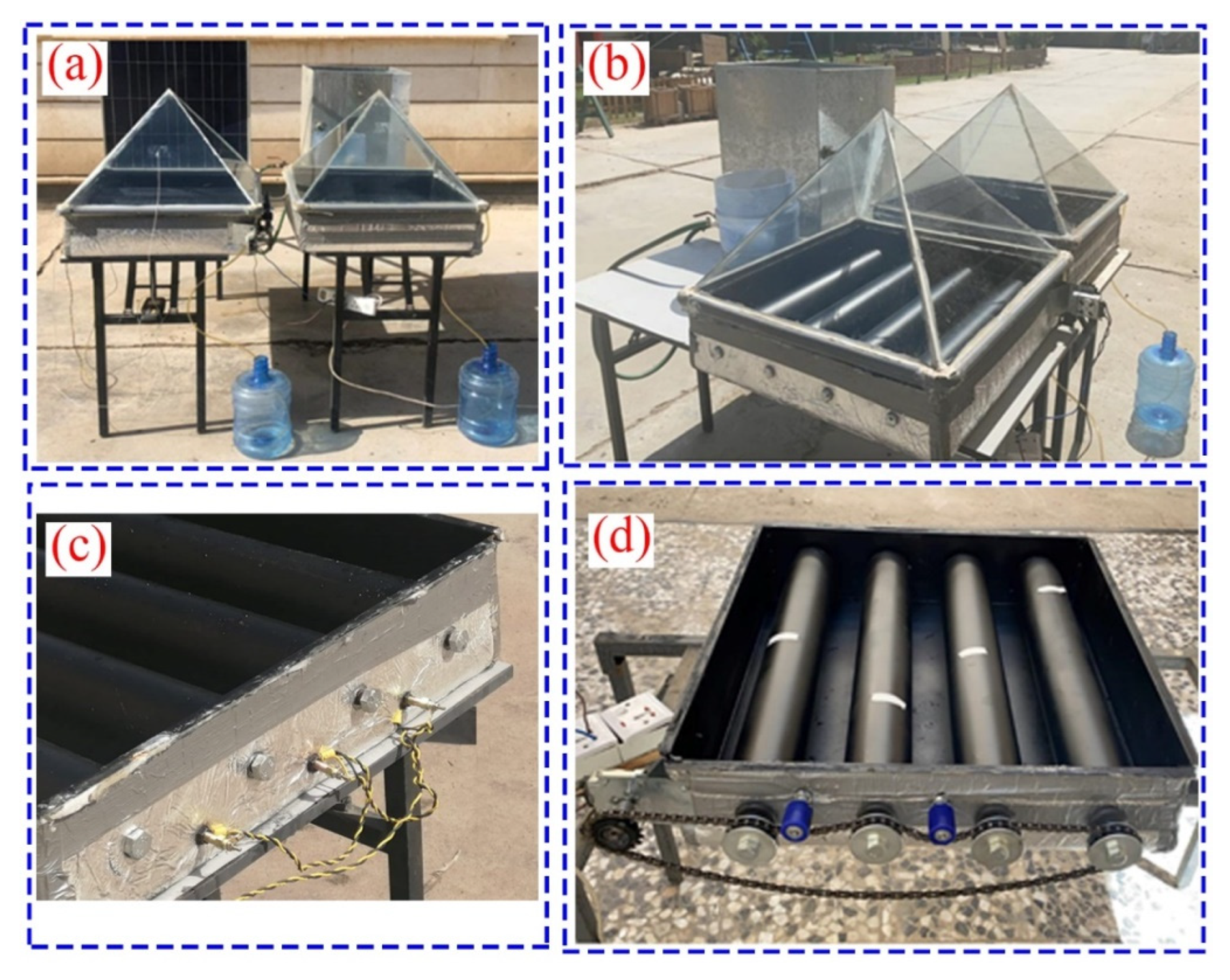
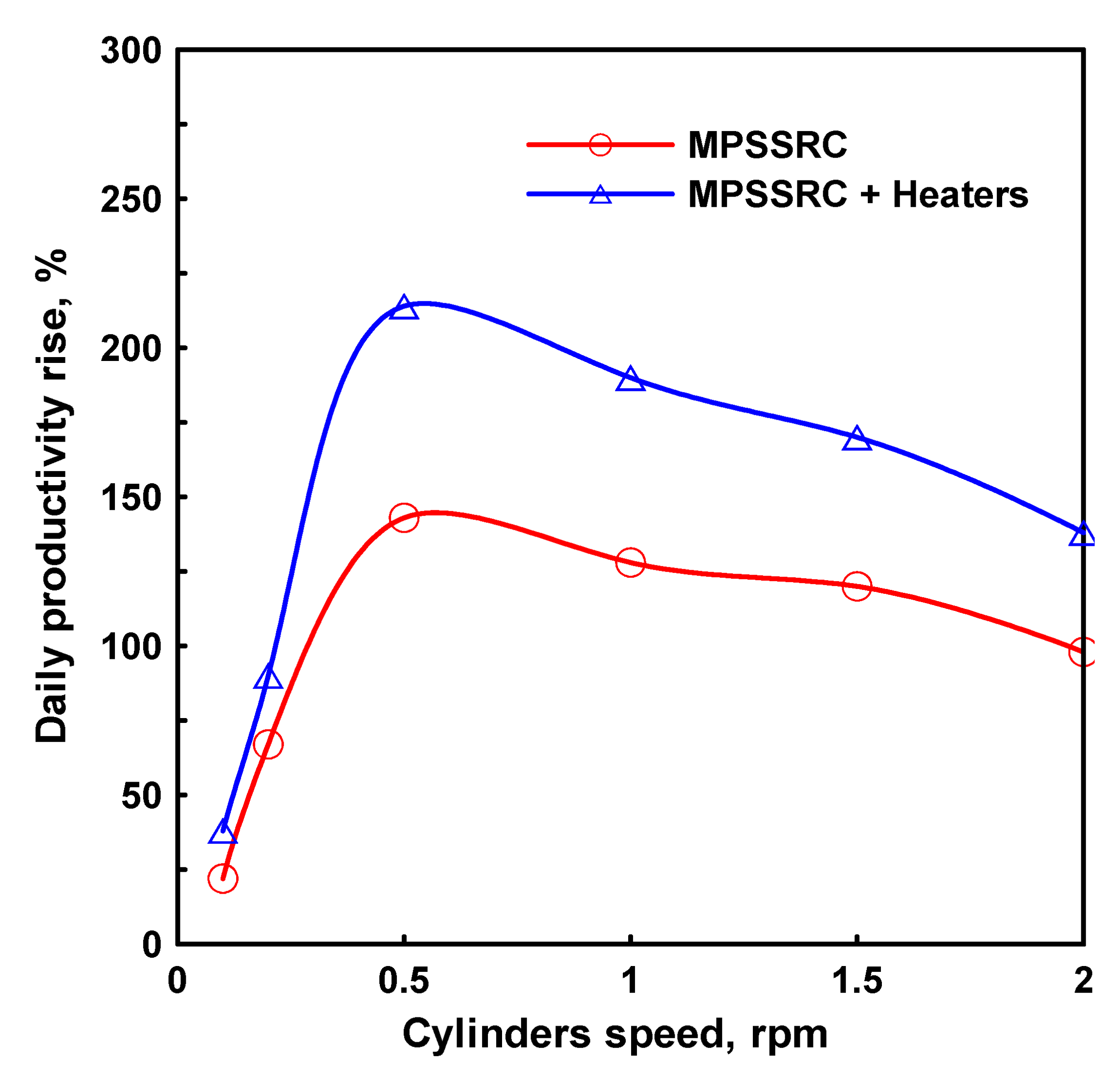
As well, Alawee et al. [62] installed four rotating cylinders and three electric heaters inside the pyramid solar distiller to increase the evaporative surface area and decrease the water depth as possible as shown in Figure 36. Results concluded that the total yields of the modified distiller with heaters and conventional still were 9100 and 2900 mL/m2 a day, respectively. Thus, the yield was heightened by 214%. Additionally, the highest increase in the yield was found at 0.5 rpm, Figure 37.
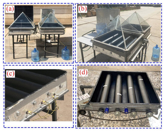
Figure 36.
Photo of the pyramid solar distiller with rotating cylinders: (a) Setup, (b) Setup with rotating cylinders, (c) rotating cylinders, and (d) basin with rotating cylinders and pulleys [62].
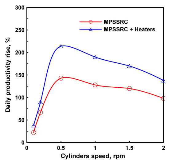
Figure 37.
Daily yield rise of modified still under different speeds [62].
4.2.5. Effect of Insulating Material and Thickness
As is well known, the working principal of the solar distiller depends on the heat transfer between the working mediums inside and outside the basin block. As a result, it is so important to insulate the distiller block from outside to prevent or eliminate the heat loss to the ambient. From this point, the importance of the insulation material type and thickness comes to be of concern. Various publications have stated that the insulation of the distiller improved the productivity by different values from 7% [63] to 180% [64] based on the insulation material type and thickness. Consequently, large variety of types of insulation materials are found in the literature such as wood, sawdust, thermocol, fiberglass, gypsum, and Styrofoam. The basis of choosing an isolation material is that the thermal conductivity of the isolation material should be low as possible. In addition, the insulation material thickness is determined based on the thermal conductivity of the material itself [44,65,66].
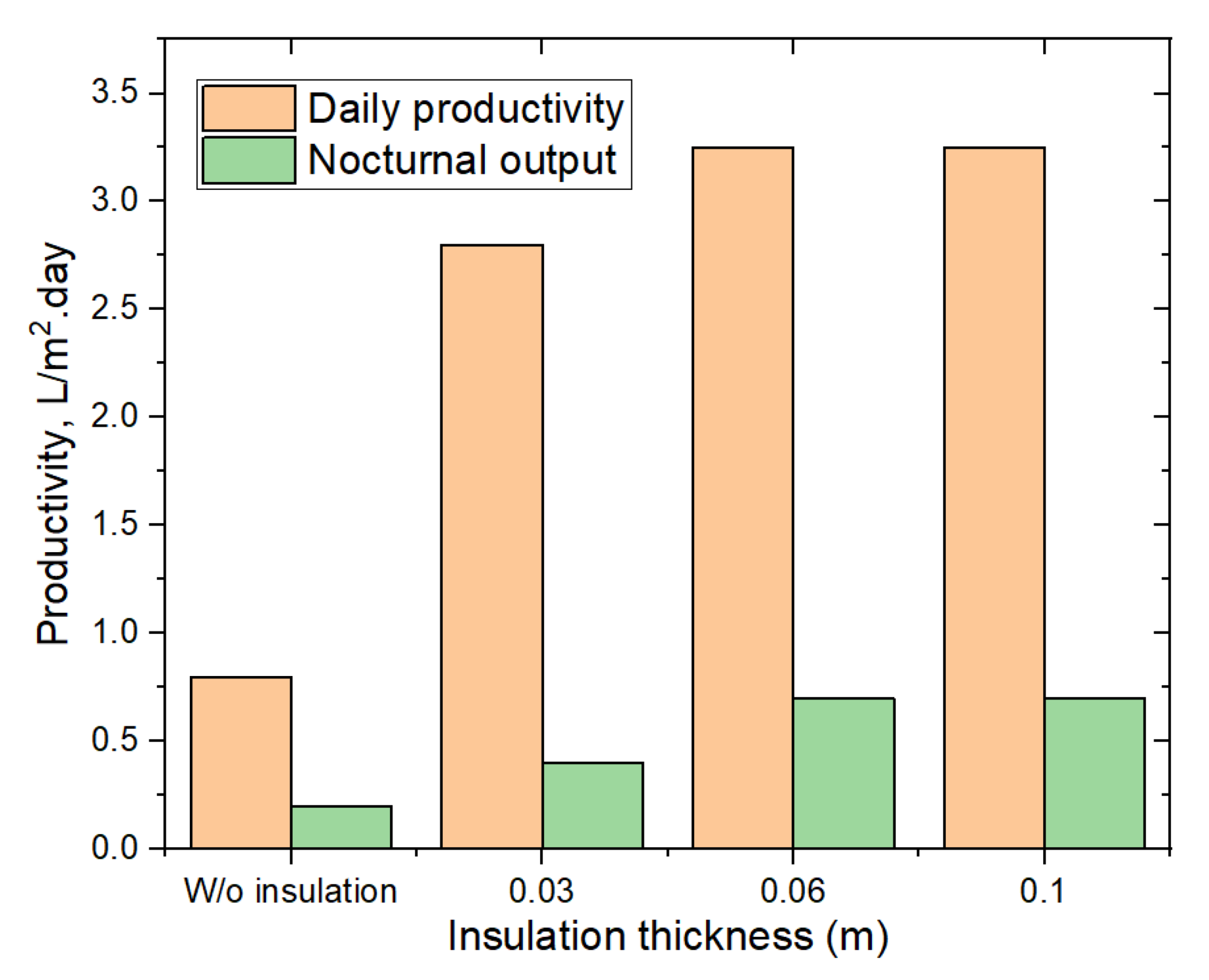
Sahoo et al. [67] enhanced the solar distiller efficiency by 11% when using the thermocol insulation. Ford et al. [68] tested the effect of properties of various insulation materials on the solar distiller performance. The authors found that the composites of cement, gypsum, and expanded polystyrene (EPS) provided good quality for the thermal isolation of the distiller. Khalifa and Hamood [65] tested the influence of insulation thickness (30, 60, and 100 mm) on the performance of the solar distiller. The authors used the Styrofoam (density of 35 kg/m3 and thermal conductivity 0.029 W/m.°C) as an insulation material for their solar distiller. The results revealed that the distiller productivity was improved from 1.81 L/m2.day at no isolation to 3.28 L/m2.day at 60 mm insulation of Styrofoam sheet as illustrated in Figure 38. Additionally, the authors proposed an equation that relates the distiller productivity with the insulation thickness, as follows.
where Y and t are the total distillate productivity (L/m2.day) and isolation thickness (m). In addition, R2 is the R-squared value of the correlations.
Y = 1023 t3 − 408.8 t2 + 1.81 and R2 = 1
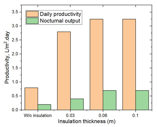
Figure 38.
The changes of distiller productivity at various thicknesses of insulation [65].
4.3. Operating Factors
Operating factors such as the difference between the glass and basin water temperatures, glass temperature, capability of hybrid systems, vacuum technology, heat storage, and basin water temperature have strong effects on the solar still performance up to great extent. Better distillate productivity is to be increased by enlarging the gap difference between the water and glass temperatures. Then, someone can cool the glass cover, and someone else can preheated the basin water to achieve that purpose. In addition, lowering the basin water depth to its minimum can achieve superior productivity of solar still. This could be achieved by using wick materials, sponges, and porous materials. Furthermore, making the basin water as a water film layer is a recent technique to augment the distillate of the distiller. Moreover, the performance of the solar still is to be improved by using a condensation unit (internal or external). Various operating factors will be discussed in the next subsections.
4.3.1. Basin Water Temperature
As is well known, the vaporization of the basin saline/brackish water needs high energy, which means that a high fuel amount will be consumed. Thus, the greenhouse gas emissions would be increased. With increasing the energy costs, fossil fuel reduction, and environmental concerns, the traditional desalination techniques are not sustainable. The renewable energy-driven technologies are more practical solutions due to their sustainability, no injurious emission, and availability at an affordable cost. Solar energy is a promising clean energy, used to produce clean water without any carbon emissions throughout its life in addition to being used directly without the inevitable loss during thermodynamic energy conversion from fossil fuels. Some scientists used the solar energy as a catalyst to raise the temperature of the water inside the basin solar still. This could be achieved by using the solar collector, reflectors, and heat exchangers. The main function of these devices is to focus the solar rays on a specified area, which is always the saline water either before feeding the distiller or in the still basin itself. Moreover, as recognized, the higher the basin water temperature, the better the performance of the solar distiller. This is because raising the water temperature increases the evaporation rate, and hence, the distillate productivity of the solar still is augmented.
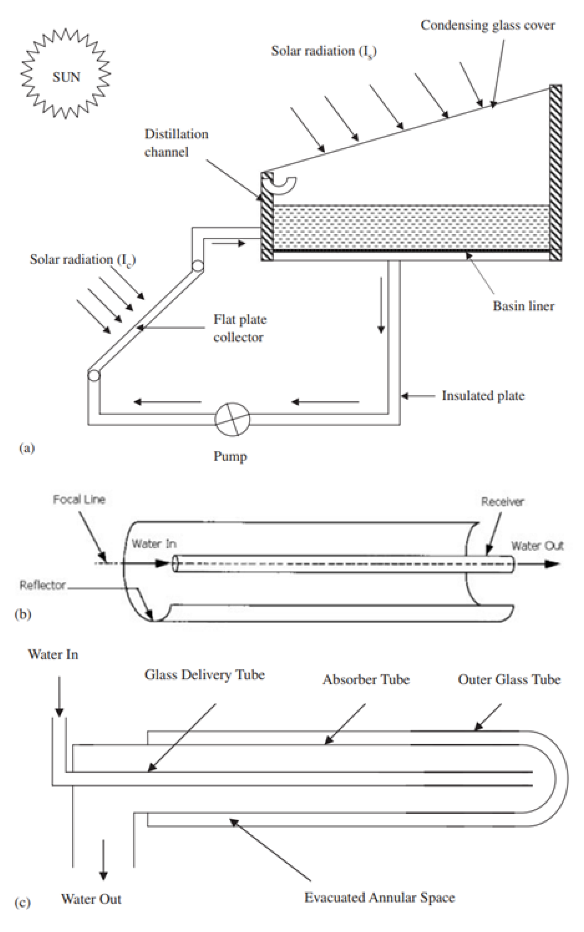
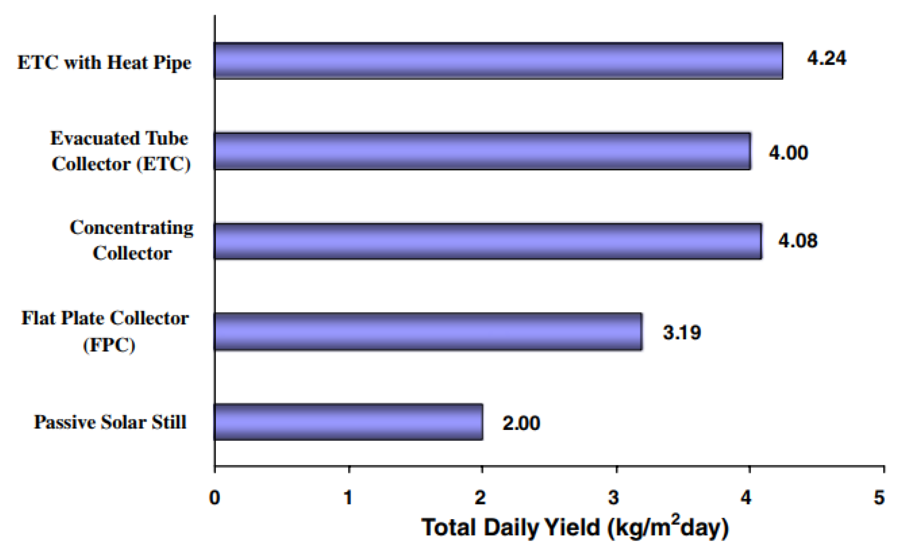
Tiwari et al. [66] studied the effect of integrating all types of solar collectors to the active solar distiller, as illustrated in Figure 39. Their results suggest that the distillate of the active distiller was superior when using the flat plate solar collector as compared to that of the other collectors as shown in Figure 40. In addition, the thermal efficiency and exergy efficiency of the solar distiller with flat plate solar collector were 5.6–19.1% and 0.25–0.85%, respectively.
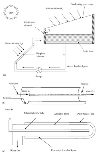
Figure 39.
Schematic of the investigated active distiller with (a) flat plate collector; (b) cylindrical concentrating collector; and (c) Owens Illinois (OI) evacuated tube collector [66].
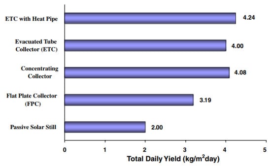
Figure 40.
Comparison of the total daily distillate for active solar stills [66].
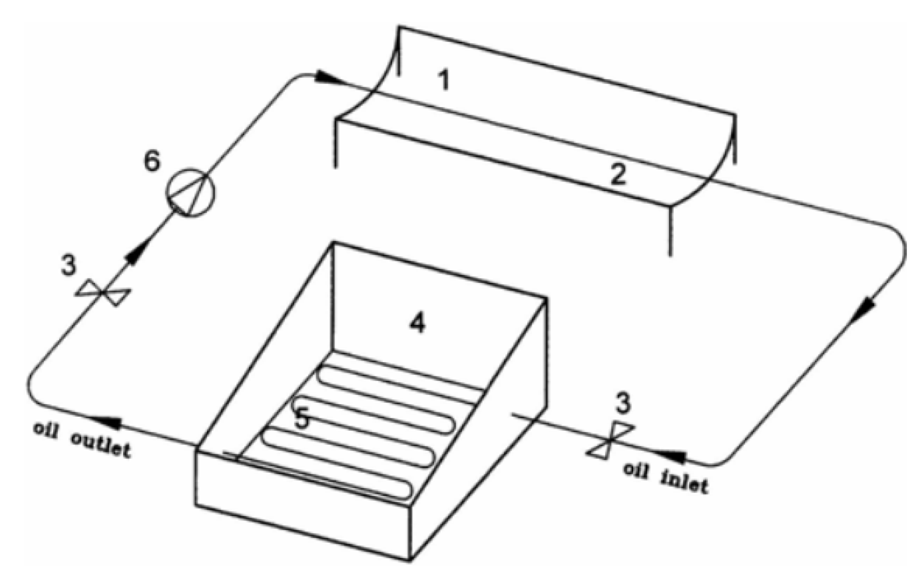
Rai and Tiwari [63] increased the solar distiller productivity by 24% when using a flat plate collector. This is because the flat plate collector raised the basin water temperature, which leads to raise the vaporization rate and distillate productivity. Additionally, incorporating the flat plate solar collector to the solar distiller enhanced the distillate by 2.31 times that of the solar distiller without the collector [69]. Abdel-Rehim and Lasheen [70] integrated the solar parabolic trough concentrator to the solar still with heat exchanger to improve its performance, as shown in Figure 41. The authors improved the distillate of the solar distiller by 18% due to the proposed modification. MohanRai et al. [71] investigated the effect of incorporating single flat plate collector and double flat plate collector to the solar distiller in series. The authors reported that the solar distiller productivity was improved by 309% and 200% when using the double and single flat plate collectors, respectively, where the distillates of the modified distillers were 6.5 and 4.7 L/m2.day, respectively, as compared to 2.1 L/m2.day for the conventional solar still. Consequently, integrating the solar collectors to the solar stills would improve their productivity to a great extent.
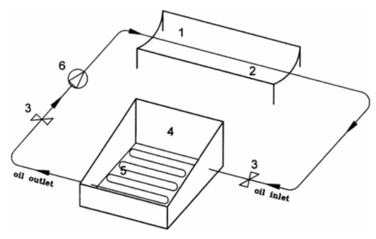
Figure 41.
Scheme of the solar still with the solar parabolic trough concentrator and heat exchanger [70]: (1) Solar parabolic trough concentrator, (2) Oil pipe, (3) Control valve, (4) Solar still, (5) Heat exchanger, and (6) Pump.
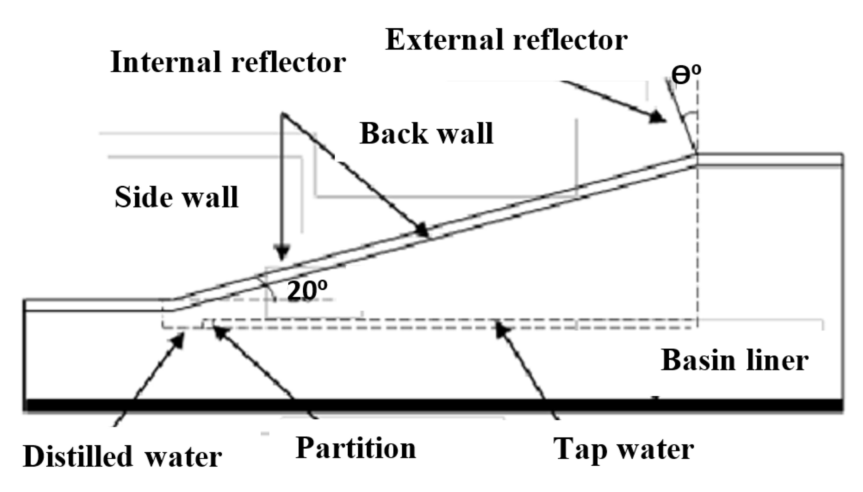
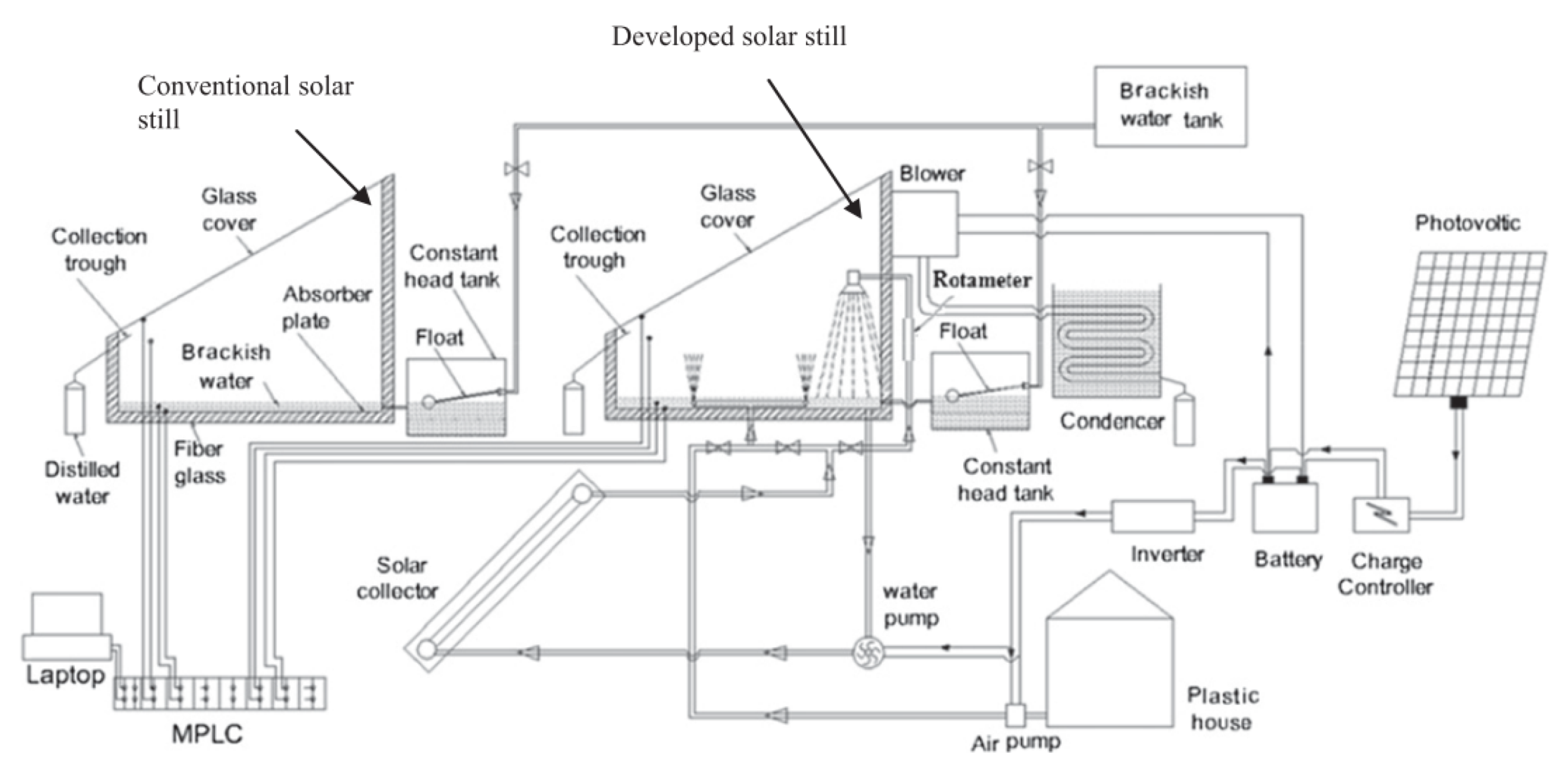
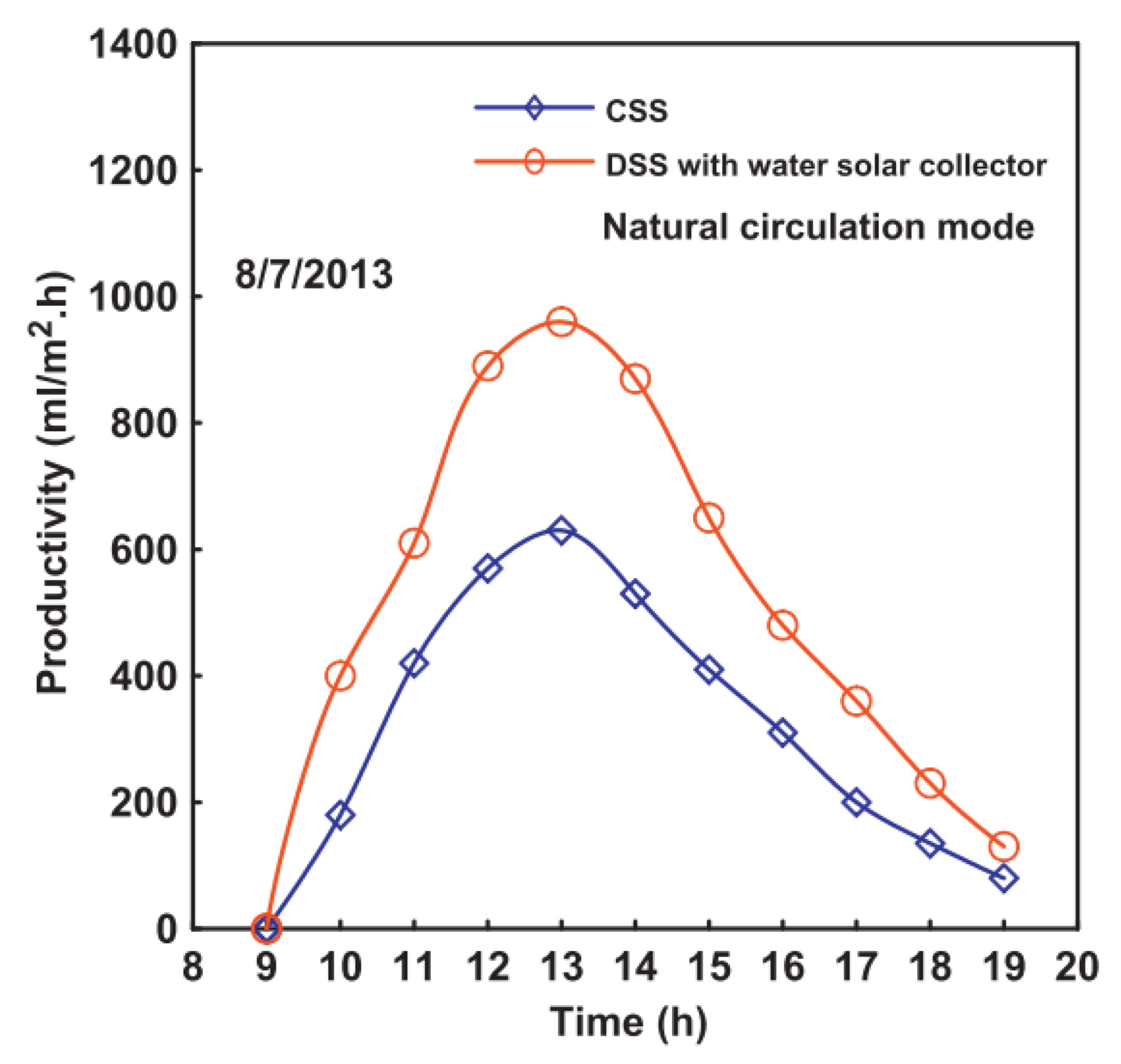
Moreover, Hiroshi [72] fixed internal and external reflectors on the solar still to increase the input solar energy incident on the basin water, as shown in Figure 42. This led to raising the basin water temperature, and hence, increased the evaporation rate of the basin still. He concluded that the freshwater productivity of the solar distiller would be improved when tilting the external mirror backward during summer and tilting forward for the rest of the seasons. In addition, Eltawil and Omara [73] connected the solar distiller to flat plate solar collector, spraying unit, external condenser, and solar air collector to increase the basin water temperature, as pictured in Figure 43. The authors reported that the distillate of the developed solar still (DSS) was better than that of the conventional solar still (CSS) with integrating the solar collector as observed from Figure 44. The solar distiller productivity was enhanced by 51–148% based on the operating conditions.
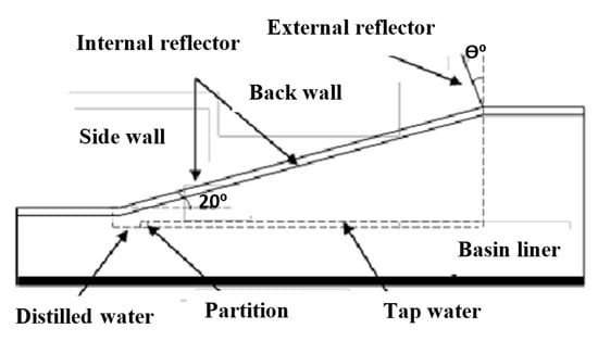
Figure 42.
Single basin solar distiller with internal and external reflectors [72].
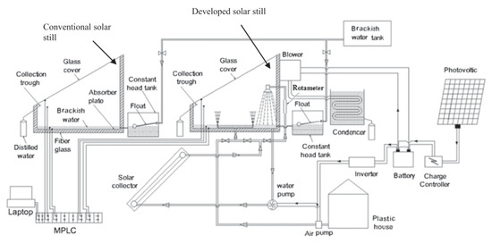
Figure 43.
Scheme of the traditional distiller and improved distiller with the flat plate collector and hot air [73].
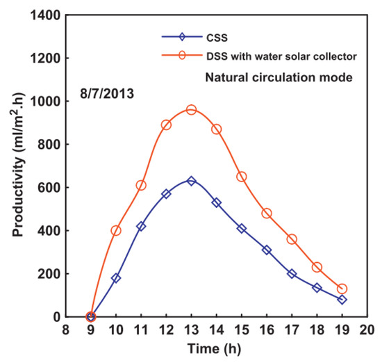
Figure 44.
Hourly changes of the productivity of solar still when using water solar collector [73].
Additionally, using the inner and outer mirrors enhanced the solar still distillate by 72.8%, 40.33%, and 7.54% during the winter, spring, and summer, respectively [74]. Moreover, the most important parameter when using the external reflector is the inclination angle of the reflector. This angle should be below 25° for the external and internal mirrors and that the optimal angle should be 10°–50° according to the running season.
4.3.2. Feed/Supply Water Temperature
As is well known, the solar still productivity and efficiency rely on the basin water temperature. Increasing the basin water temperature means improving the rate of generating vapor, and hence, the distillation production could be enhanced. As a result, there are numerous publications preheated the basin water before feeding to the distiller basin to augment the productivity. Starwin and Lawrence [75] used the a solar pond and collector to preheat the saline water before feeding to the distiller. This raised the inlet water temperature, and hence, the distillate production was enhanced by 40%, as shown in Figure 45.
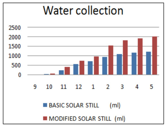
Figure 45.
Total productivity with and without water preheating [75].
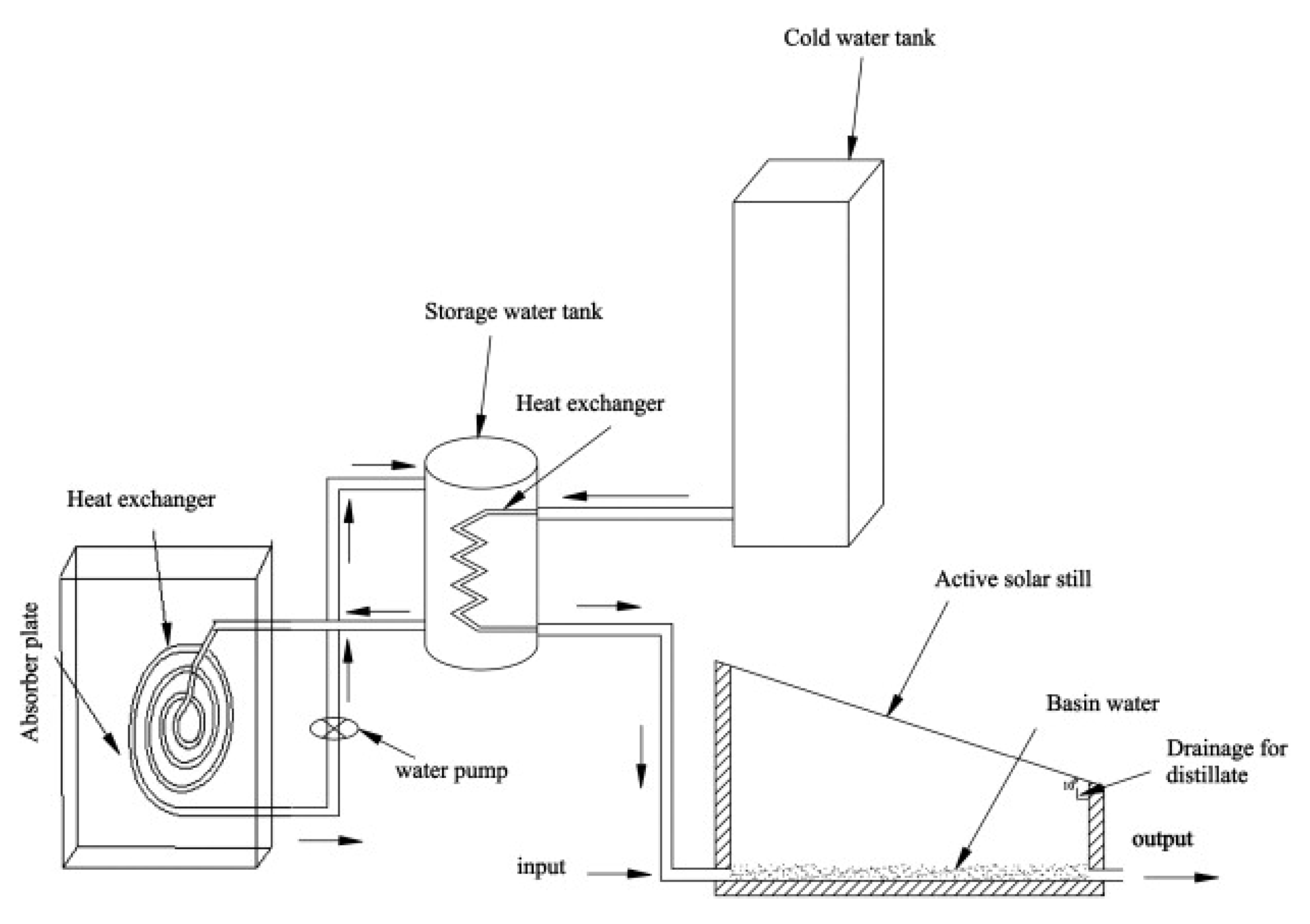
El-Sebaii et al. [76] integrated a shallow solar pond to the solar still, as shown in Figure 46. The system provided a total yield of 5.74 and 1.83 kg/m2/day with and without the ponds, respectively. The authors found that the productivity was improved by about 214%, and the thermal efficiency was enhanced by 54.98%.
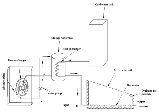
Figure 46.
Tested solar distillation system [76].
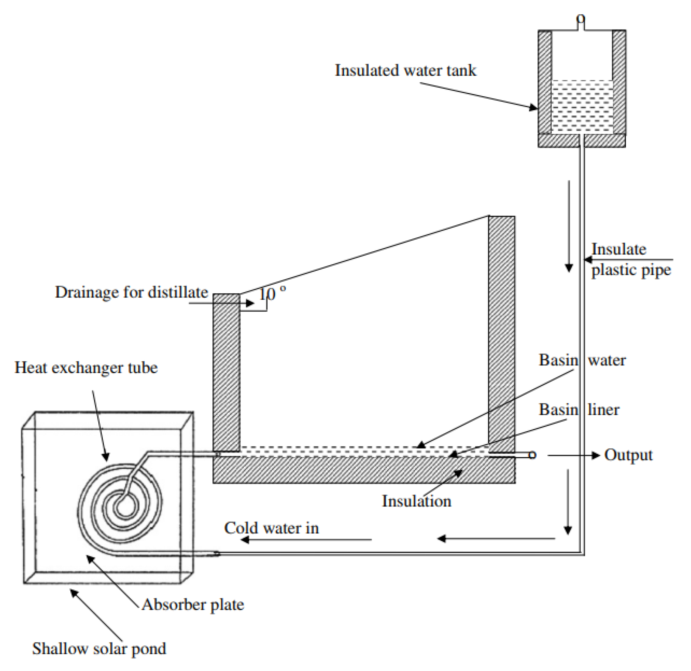
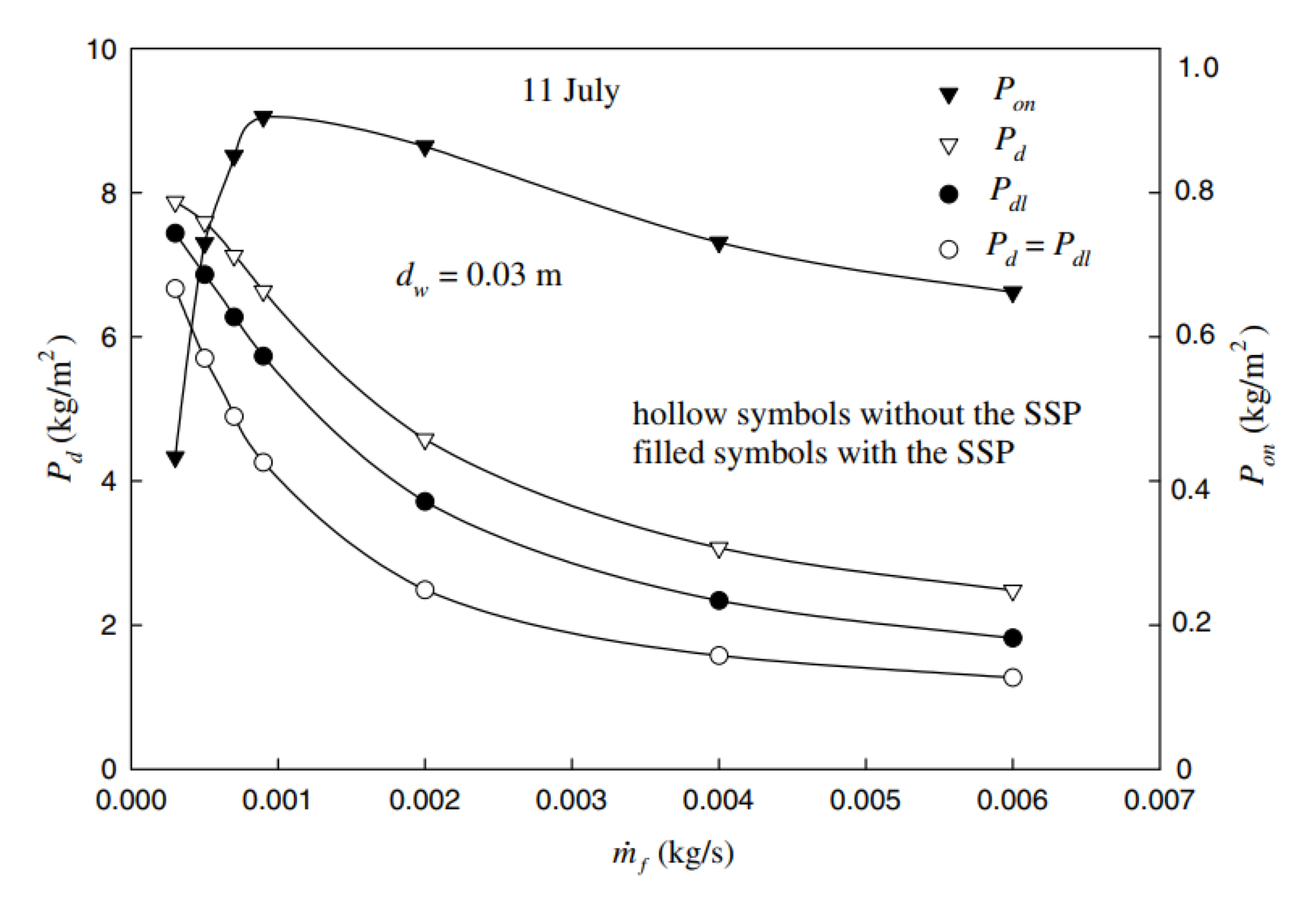
In addition, El-Sebaii et al. [77] experimentally and analytically tried to raise the basin water temperature by integrating the solar distiller with a shallow solar pond (SSP), as shown in Figure 47. Results revealed that the system distillate was better when using the SSP as illustrated in Figure 48. Moreover, the solar distiller freshwater distillate and efficiency were enhanced by 52.36% and 43.80% when using the SSP as compared to that of the system without the SSP.
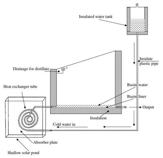
Figure 47.
Scheme of the single-basin distiller with the shallow solar pond [77].
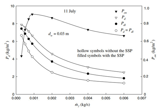
Figure 48.
Daylight and overnight distillates with and without the SSP [77].
4.3.3. Applying Vacuum inside the Solar Distiller
Another important parameter that strongly affects the performance of the solar still is applying vacuum inside the solar distiller. There are numerous publications investigating the solar stills under vacuum. The main function of applying vacuum inside the distiller is to avoid any heat transfer caused by convection in the basin distiller, which leads to making the heat loss from the water in an insulated still be due to the evaporation and radiation only. In addition, in the presence of vacuum, the effect of the non-condensable gas, which reduces the rate of condensation, is also avoided.
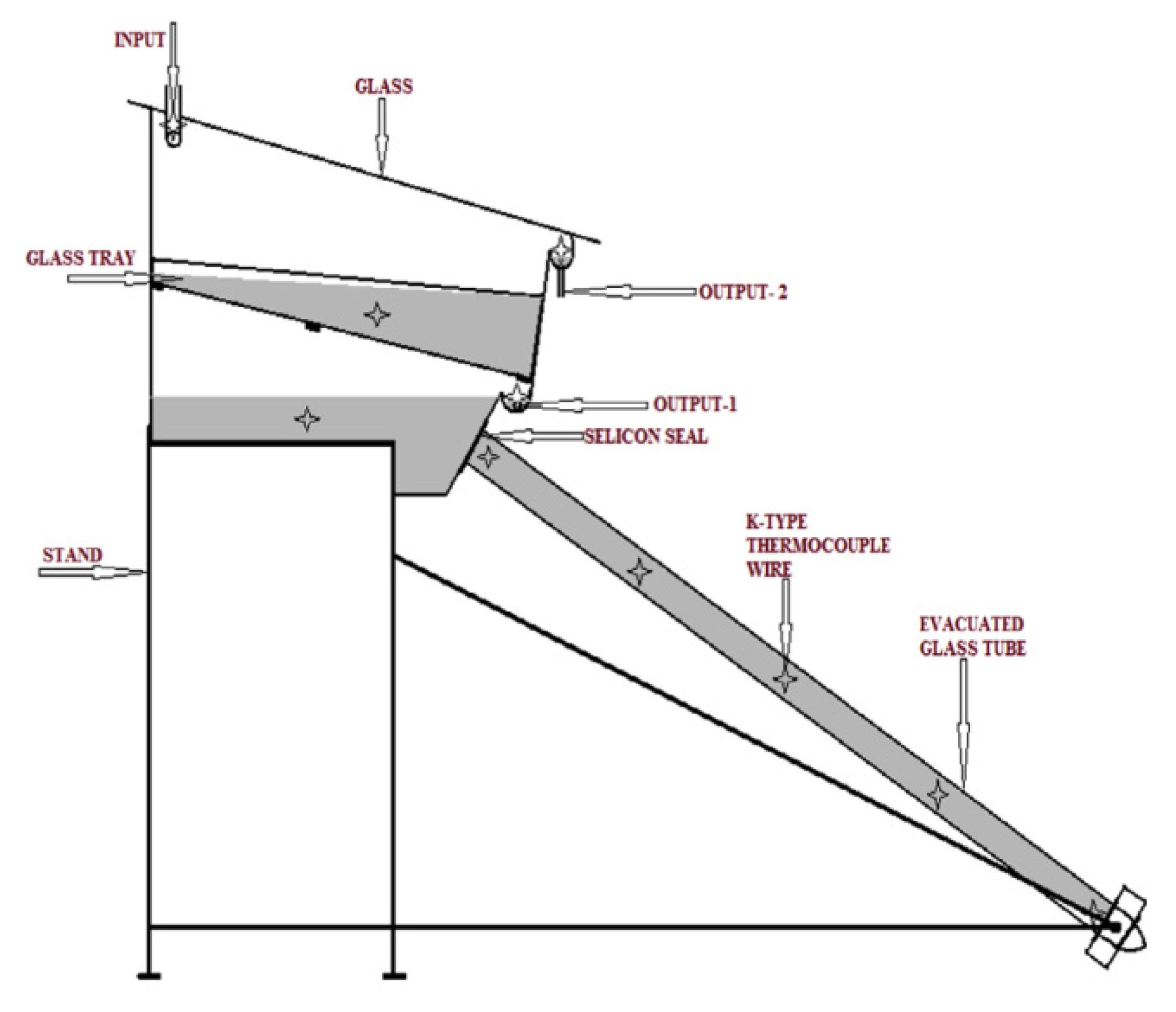
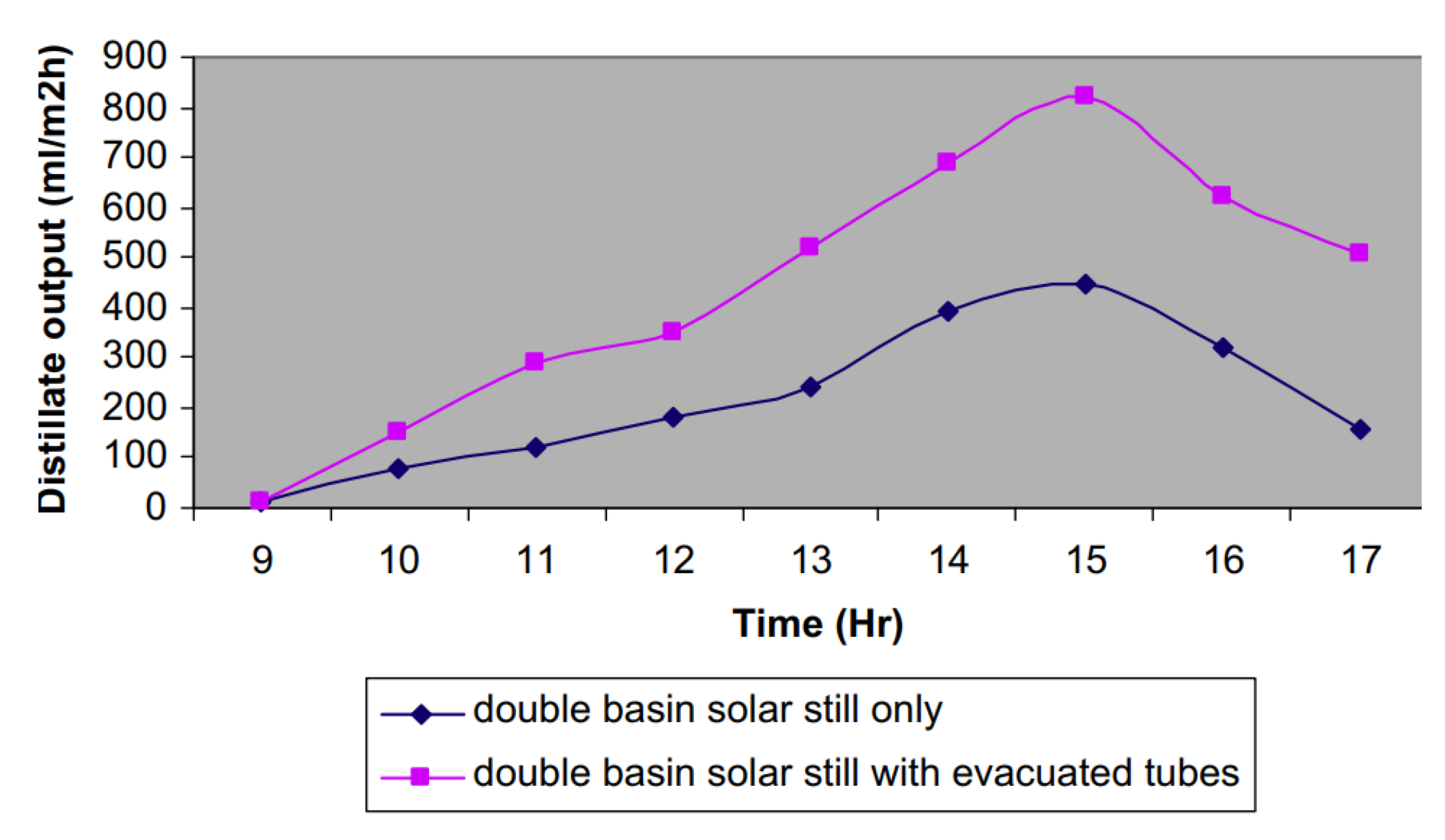
Panchal [78] investigated the effect of integrating a vacuum tube at the distiller lower side, as shown in Figure 49. Results revealed that the freshwater productivity of the double basin solar distiller with vacuum tubes was more than that without vacuum tubes, as shown in Figure 50. The author reported that the total yield of the distiller was improved by 56% due to the proposed modification.
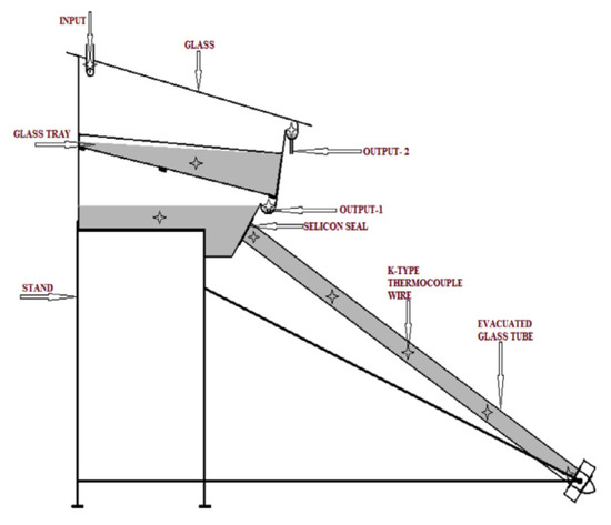
Figure 49.
Schematic of the solar distiller with vacuum tubes [78].
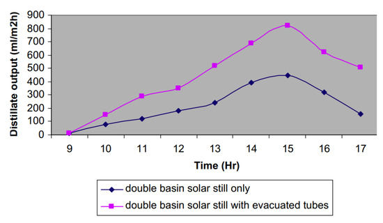
Figure 50.
The hourly distillate of the double basin solar distiller with and without vacuum tubes [78].
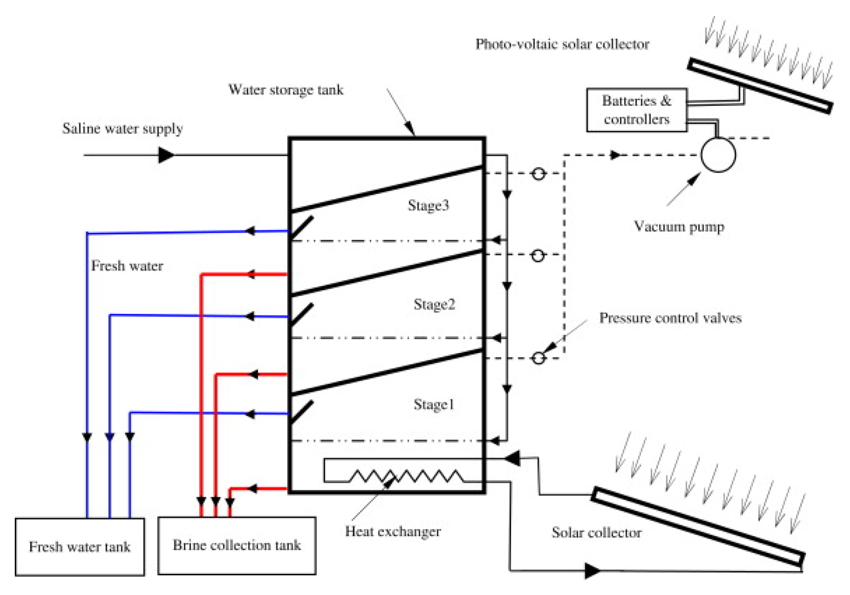
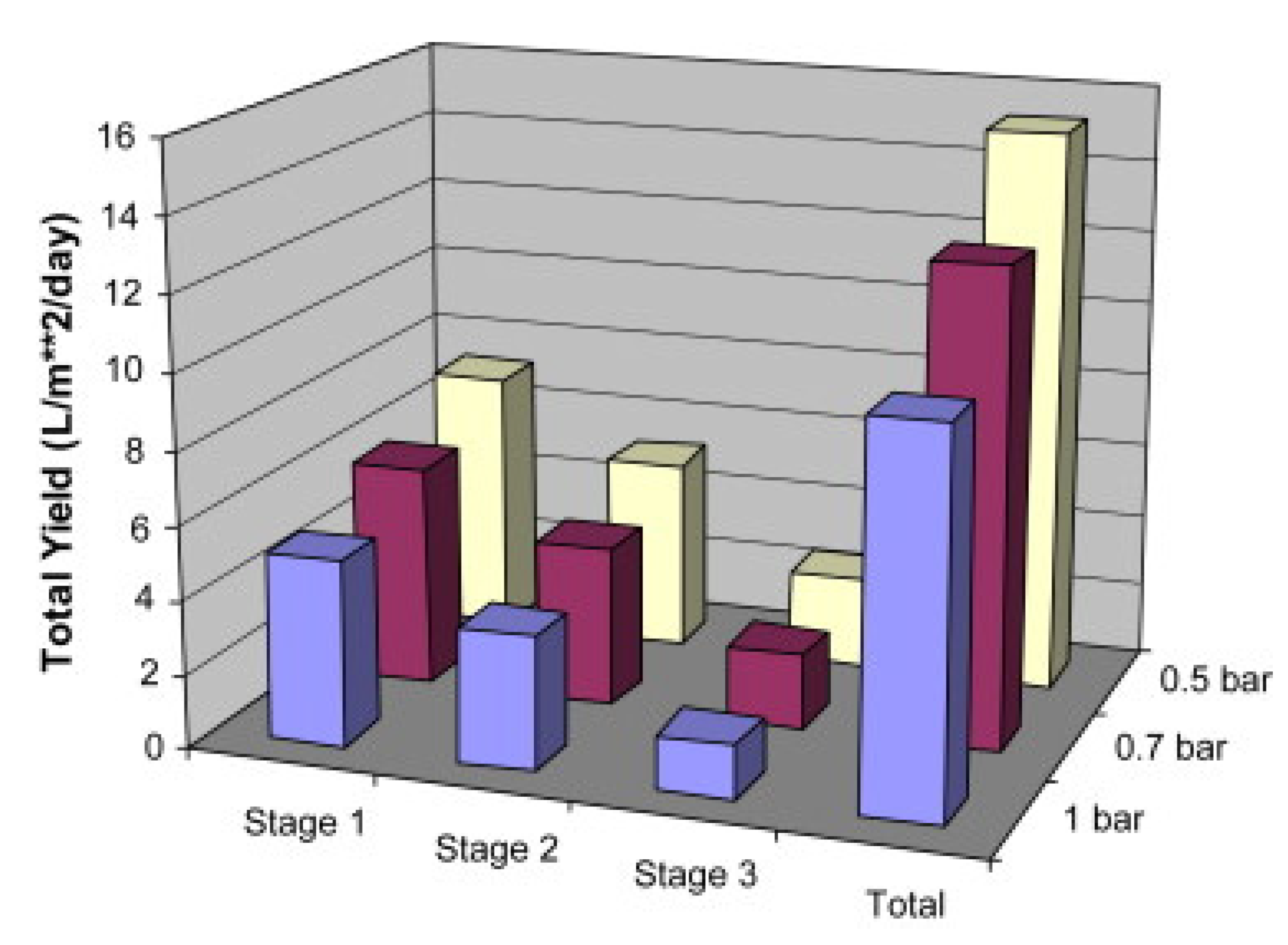
Additionally, Ahmed et al. [79] examined the effect of applying vacuum inside the multistage evacuated solar distiller, as shown in Figure 51. The authors concluded that the total and individual stages daily distillates were better in the case of increasing the vacuum inside the system, as illustrated in Figure 52.
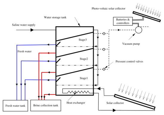
Figure 51.
Schematic of the evacuated multistage solar distiller [79].
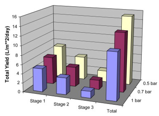
Figure 52.
Total and individual stages daily distillates at vacuum conditions [79].
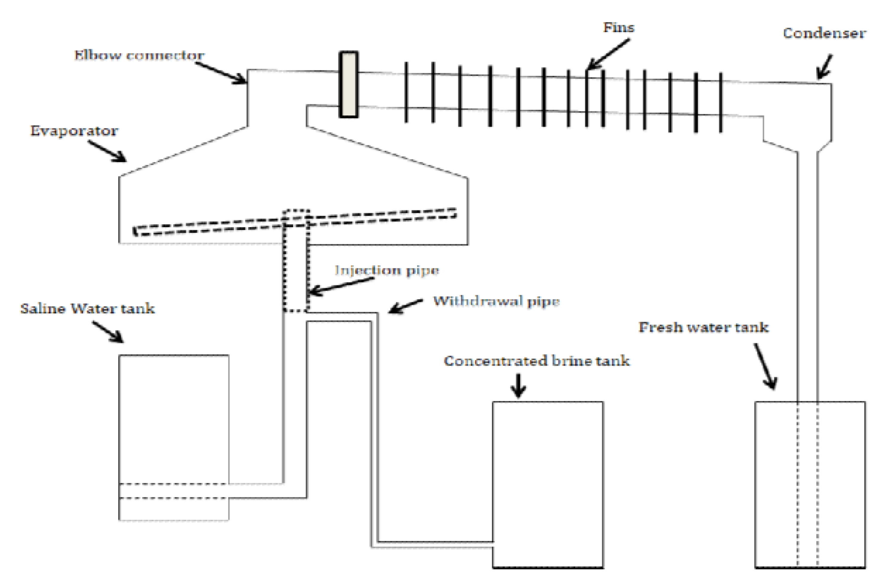
Al-Kharabsheh and Yogi [80] tested experimentally and theoretically the effect of using low-grade solar heat in a solar distillation system, as shown in Figure 53. The authors stated that a vacuum of 4 Pa (abs) or less could be generated as a function of the air temperature at which the condensation process occurs. Under the vacuum conditions, the water is evaporated quickly at low pressure and temperatures. The evaporator was used to generate vapor from the basin water, and this vapor was condensed in the condenser to be accumulated from the condenser outlet. This arrangement enhanced the distillate output from 3–4 L/m2.day for the conventional still to 6.5 L/m2.day for the modified distiller.
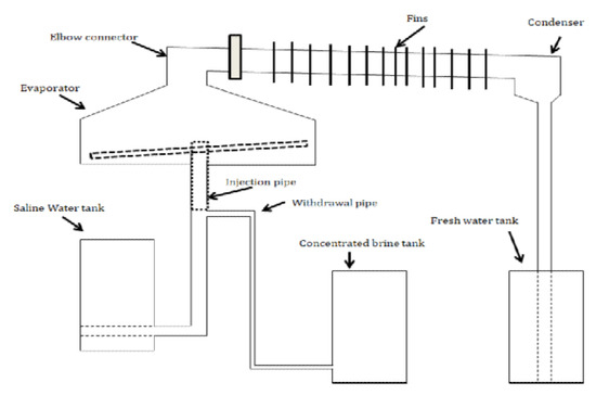
Figure 53.
Distillation using low-grade solar heat [80].
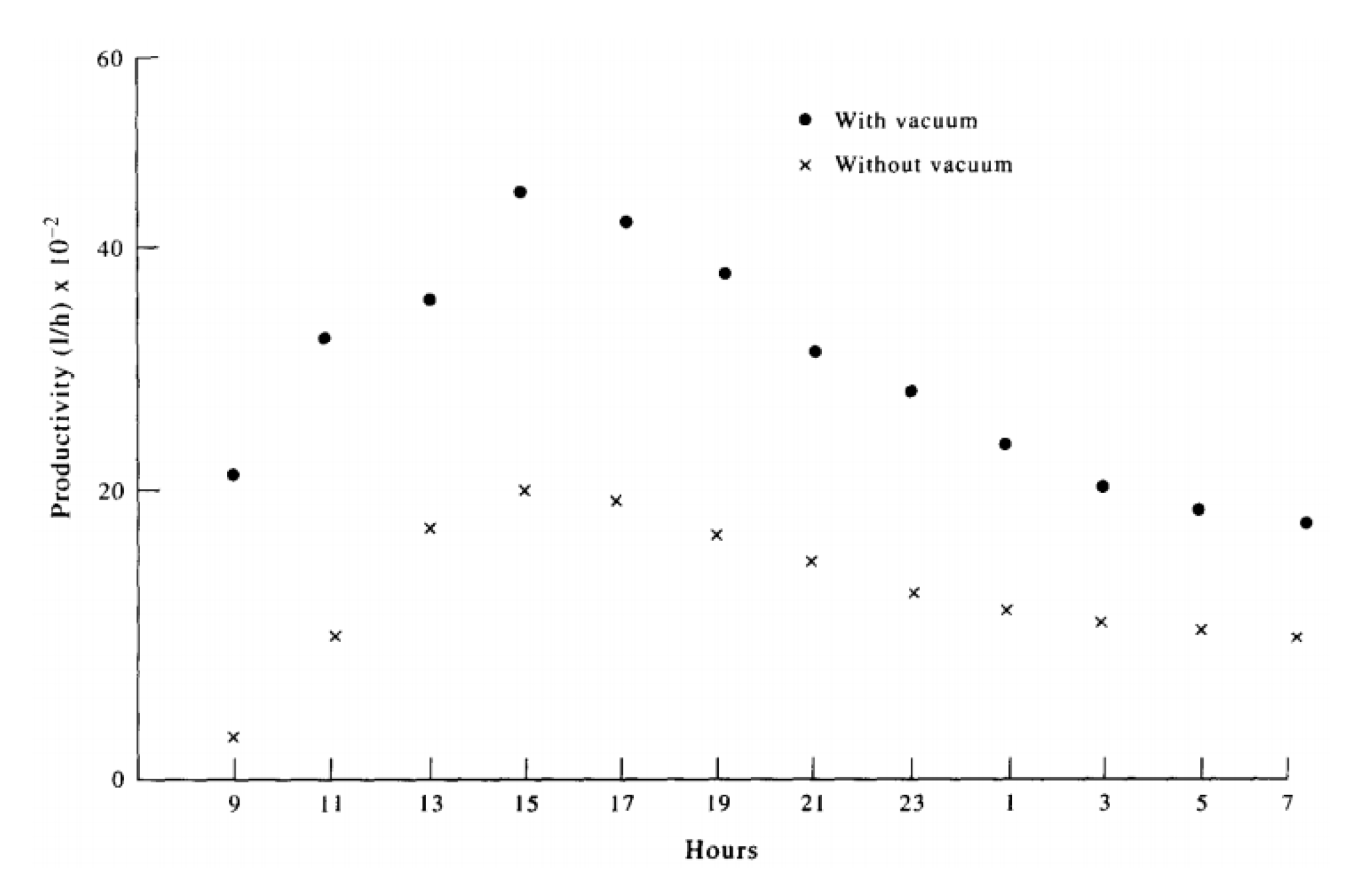
AI-Hussaini and Smith [81] investigated the impact of providing vacuum inside the solar distiller on its performance. The presence of vacuum inside the solar distiller has the merits explained at the beginning of this section. Finally, the vaporization and condensation rates are improved. In addition, the hourly distillate was augmented when applying vacuum within the system as shown in Figure 54. Additionally, the total productivity is improved by 100%, where it was increased from 1.45 L/m2.day to 3.39 L/m2.day in a typical winter day.
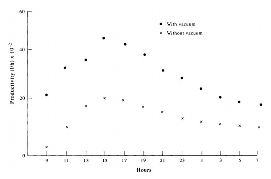
Figure 54.
Solar still productivity during a typical summer day [81].
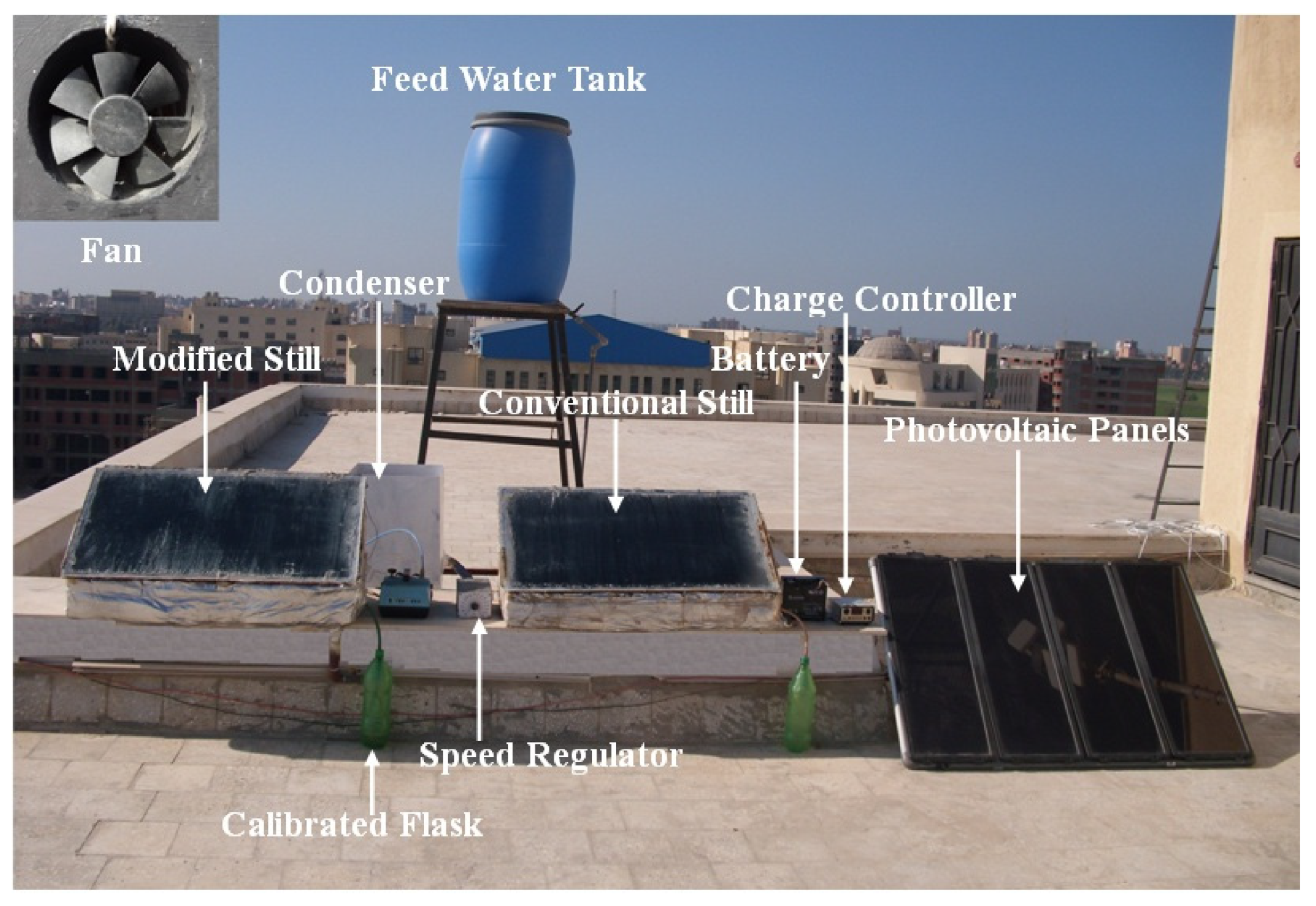
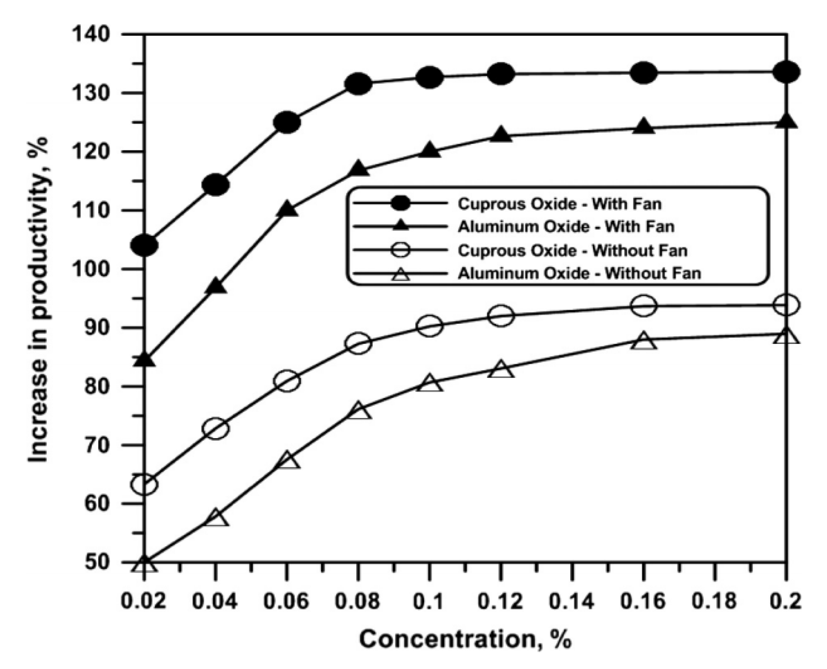
Nassar et al. [82] applied a vacuum inside the solar desalination system integrated with a reflector. The system created a vacuum pressure of 25 kPa absolute, which was enough to decrease the boiling of the basin saline water. Providing the vacuum inside the distiller improved the distillate yield from 5 L/m2.day to 20 L/m2.day with an improvement of 900%. Moreover, Kabeel et al. [83,84,85] integrated a vacuum fan to the conventional solar distiller to withdraw part of the generated vapor from the distiller and make a vacuum inside the distiller as shown in Figure 55. Moreover, the authors tested the effect of using nanomaterials on the performance of solar stills. Their results revealed that the productivity of the distiller was augmented by 133.64% when using the vacuum fan and cuprous nanoparticles, as illustrated in Figure 56.
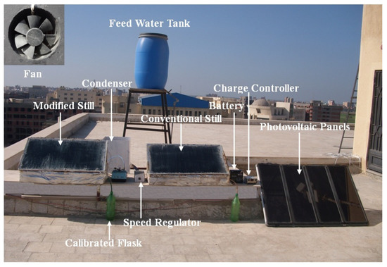
Figure 55.
A photograph of the solar still with fan [83,84].
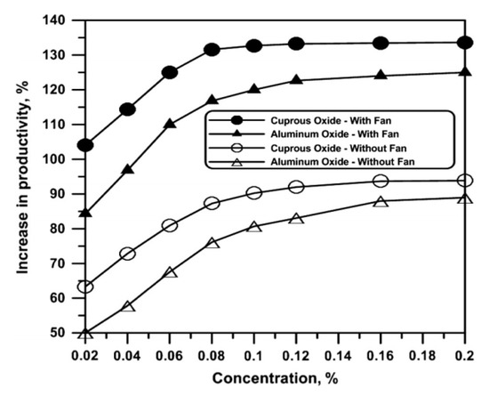
Figure 56.
The increase in productivity of the modified distiller when using vacuum and nanoparticles [83].
4.3.4. Heat Absorbing and Thermal Storage Materials
Introducing the heat absorbing and thermal storage materials to be used in the solar distillers is known modification to enhance the solar still performance. As is well known, improving the absorptivity of the absorber liner will lead to enhance the absorptivity of the solar radiation and heat transfer characteristics of the basin water. As explained above, the greater the difference between the water and glass temperatures, the better the performance of the solar still. Then, the scholars used some additional heat absorbing and thermal storage materials that can be placed with the basin water to raise the water temperature or extend the period of high water temperature. This could be used through the sun times or the cloud or night times. Thus, different heat absorbing materials such as charcoal, mixing of violet and black dyes, gravels, and black wires were used. Additionally, the positive effect of using these dyes and materials increases with increasing the basin water depth [86]. The function of these materials is to sink higher quantities of sun energy and increase the basin heat capacity, which increases the evaporation rate of the solar still. To obtain the importance of using the heat absorbing materials on the productivity of the solar distillers, Ayoub and Malaeb [87] summarized the increase in productivity occurred when using those materials in Table 3. It is obtained from the table that there are a variety in the improvement occurred when using the various heat absorbing materials in the basin distillers.

Table 3.
Increase in productivity of solar stills when using different heat absorbing materials [87].
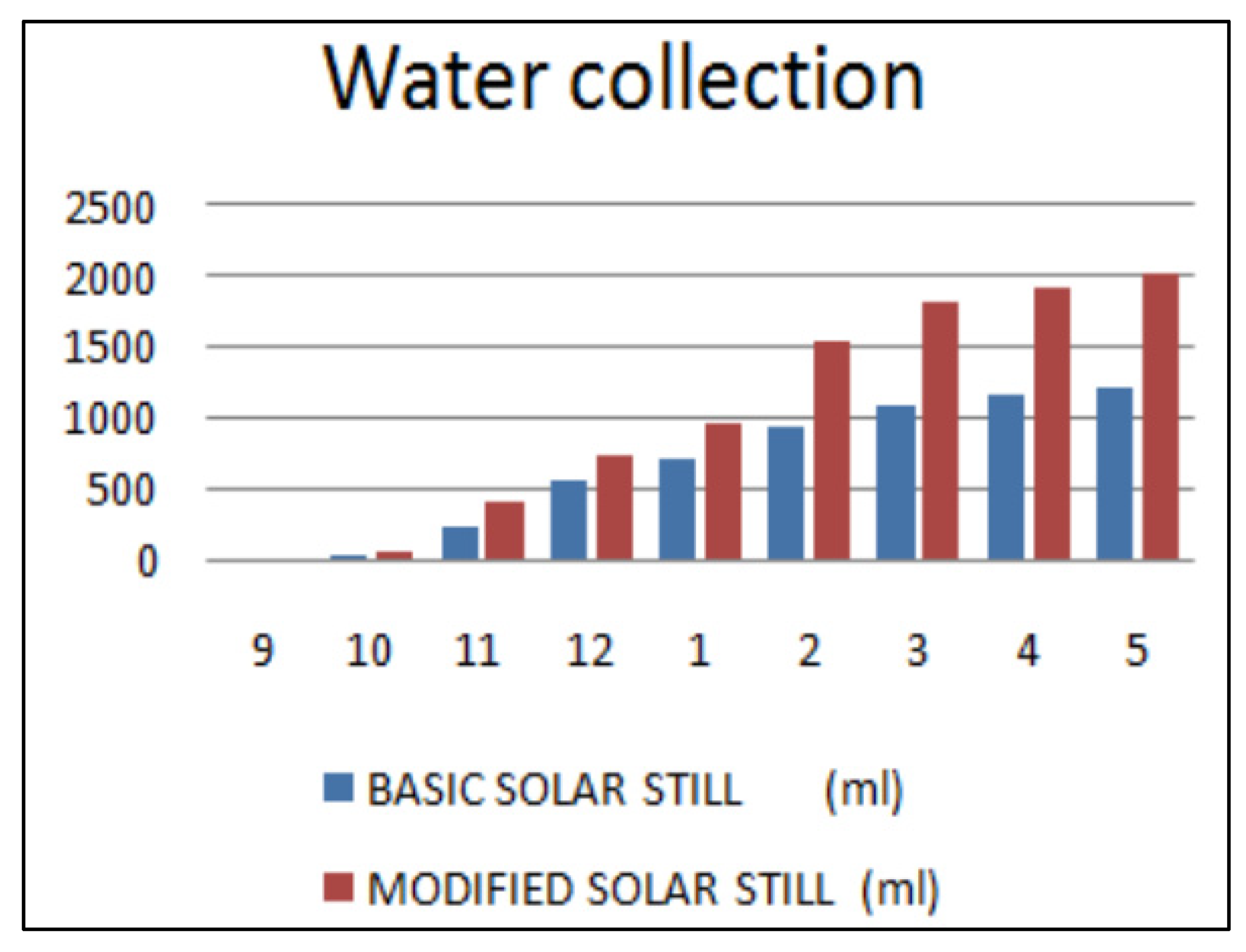
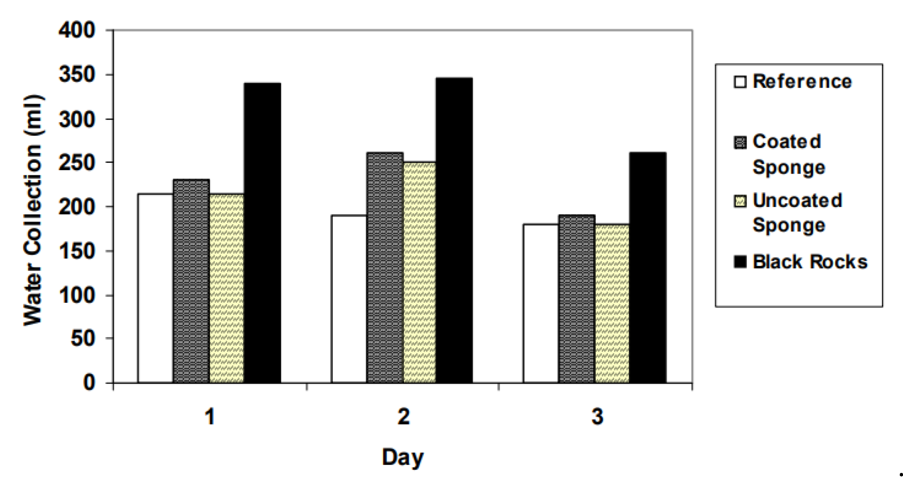
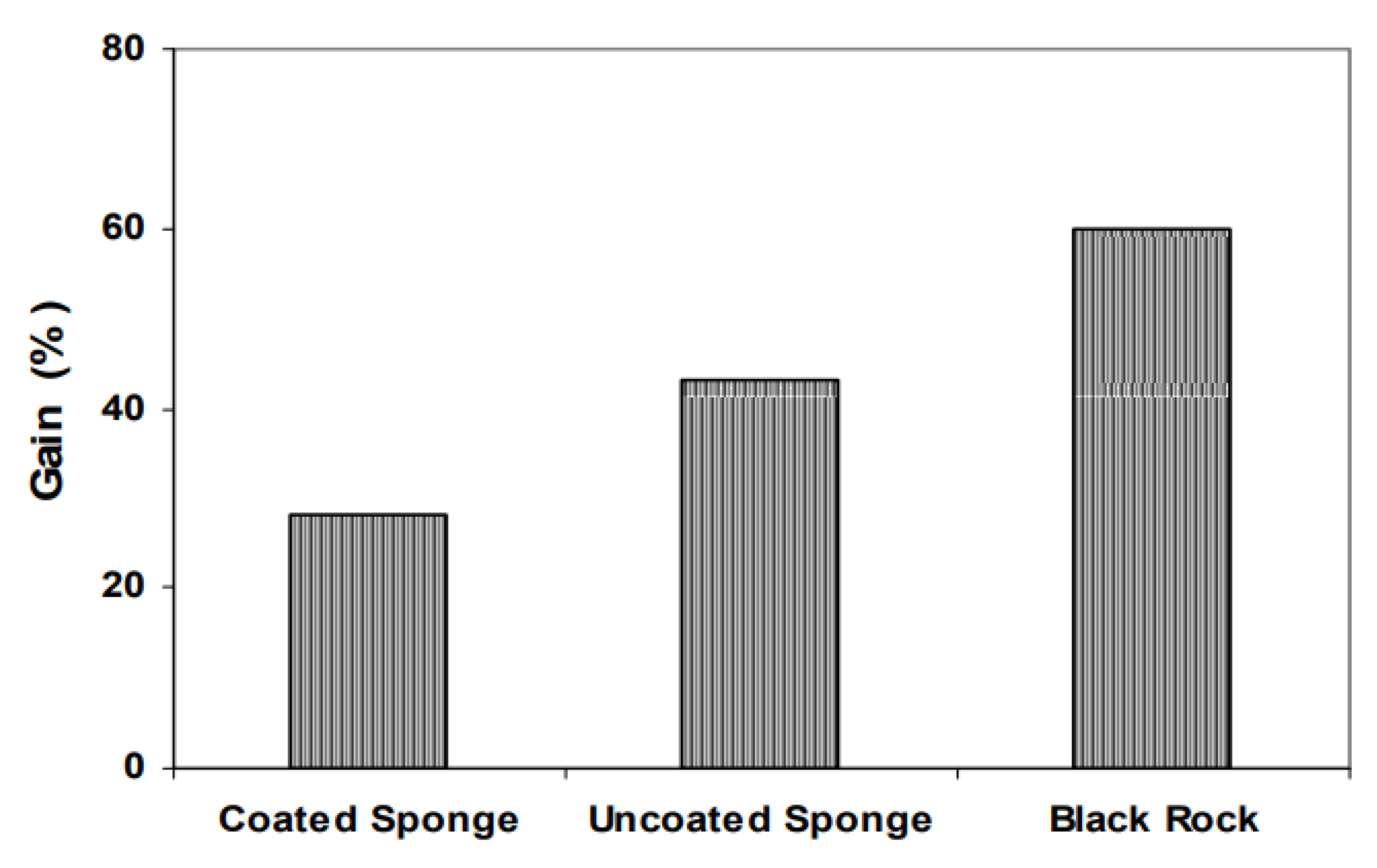
Abdallah et al. [88] tested the effect of using the absorbing materials of coated and uncoated porous media (called metallic wiry sponges) and black volcanic rocks to work as absorber liners on the performance of the solar distiller. All these materials provided better performance of solar still than that of the conventional solar still. The authors obtained that the uncoated sponge provided the best distiller performance compared to the other materials, as shown in Figure 57. In addition, the increase in productivity for the modified solar stills was 60%, 43%, and 28% when using the uncoated black rocks, uncoated metallic wiry sponges, and black rock, respectively, as illustrated in Figure 58.
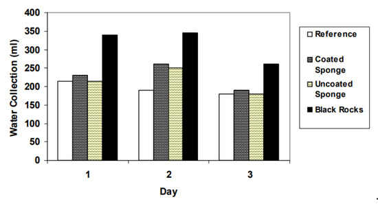
Figure 57.
Total water production for the four solar stills with and without porous materials over three days [88].
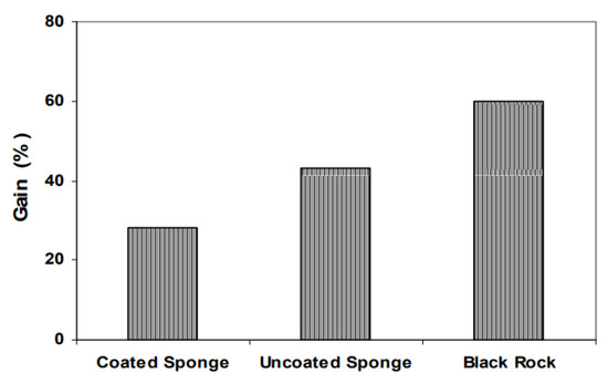
Figure 58.
Increase in productivity due to using the investigated absorbing materials [88].
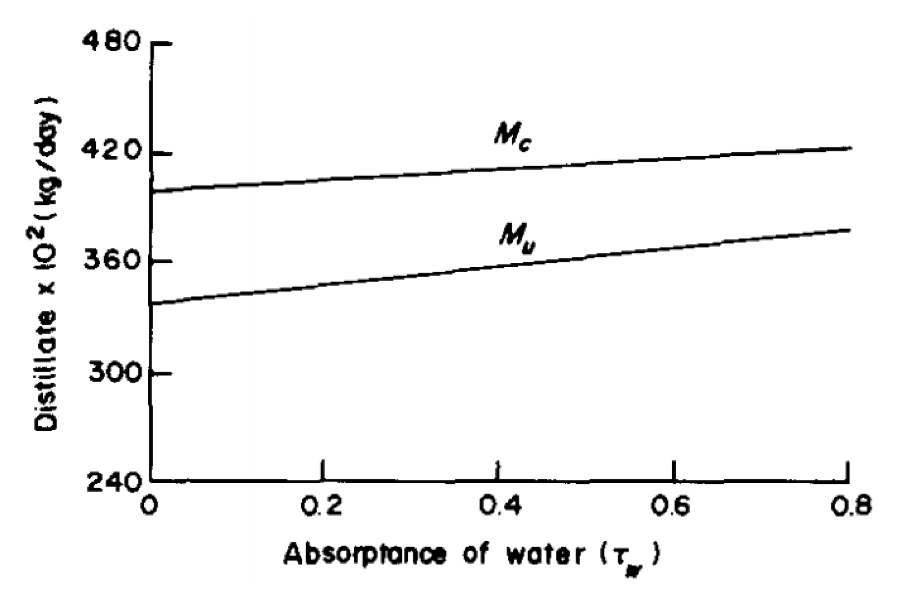
Moreover, introducing the dyes as an absorbing material is an effective technique to enhance the solar still performance. This is because the dyes obtain a higher water temperature due to the better absorption of solar irradiance. Garg and Mann [89] tested the effect of the dye color on the distiller productivity. The authors found that the solar still distillate could be augmented from 2.02 L/m2.day for the conventional distiller (with no color in water) to 2.31 and 2.53 L/m2.day when using the blue and red colors in basin water, respectively. Furthermore, Rai and Tiwari [63] examined the effect of using dye in the basin water on the distiller performance. The authors concluded that the freshwater productivity of the solar still could be increased by increasing the water absorptance, as illustrated in Figure 59, which would be achieved by using dyes.
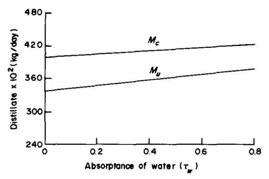
Figure 59.
Changes of the distillate production under different water absorptance [63].
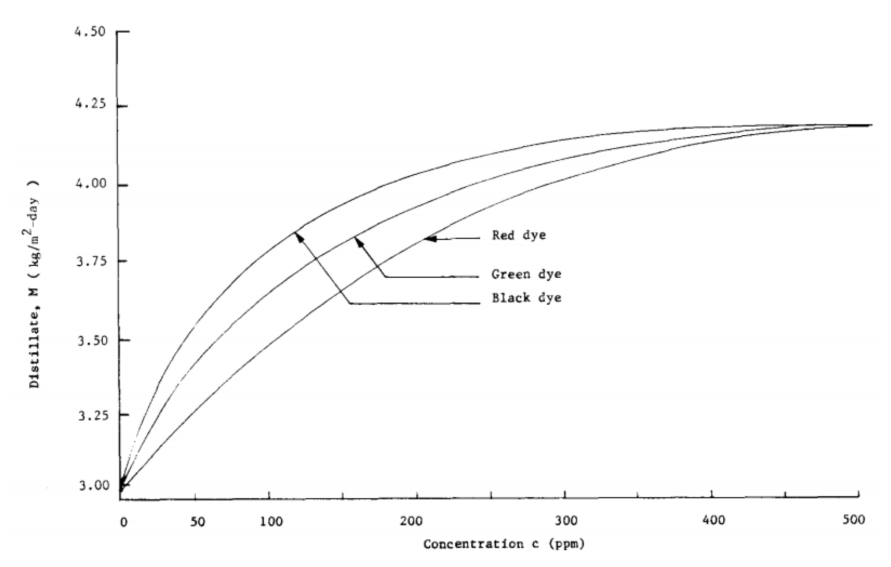
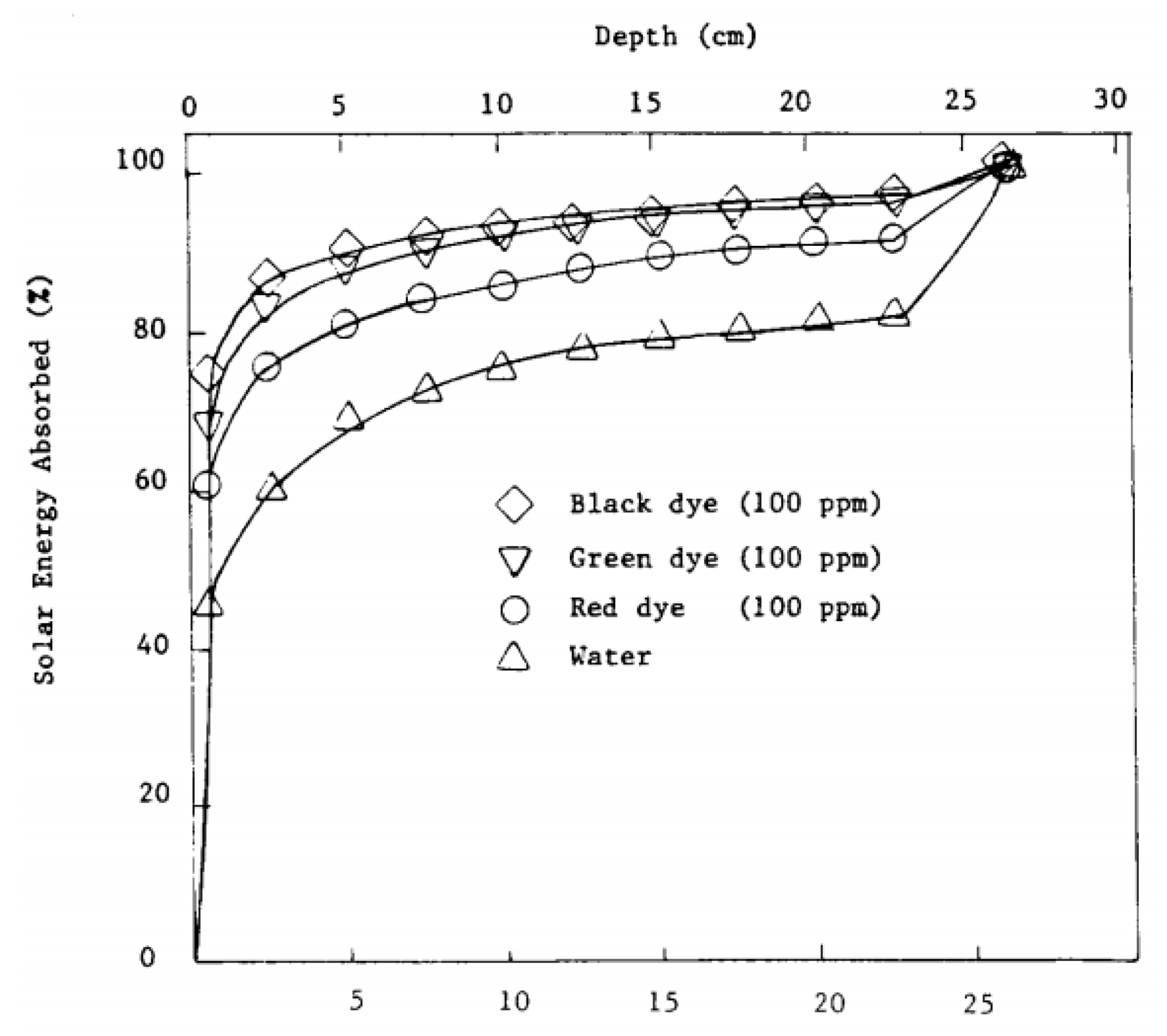
Rajvanshi [90] investigated experimentally and theoretically the effect of adding the dyes of black napthylamine, red carmoisine, and dark green at different concentrations to the basin water. The black napthylamine obtained superior performance of solar still compared to the other dyes and pure water, as shown in Figure 60. This refers to the large amount of the solar energy absorbed by the mixture of basin water and dye (solution) as illustrated in Figure 61. The black dye (at 172.5 ppm concentration) increased the freshwater yield by 29%.
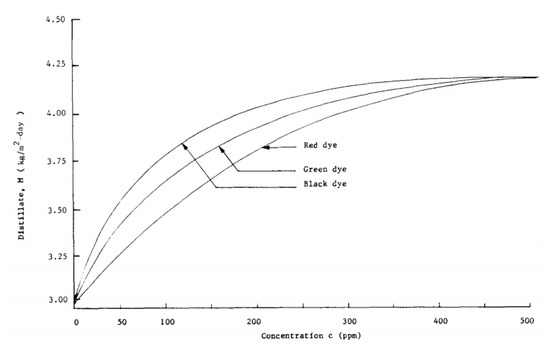
Figure 60.
Impact of dye type and concentration on distillate output [90].
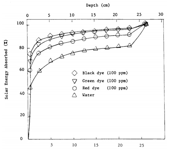
Figure 61.
The absorbed solar energy at various solution depths [90].
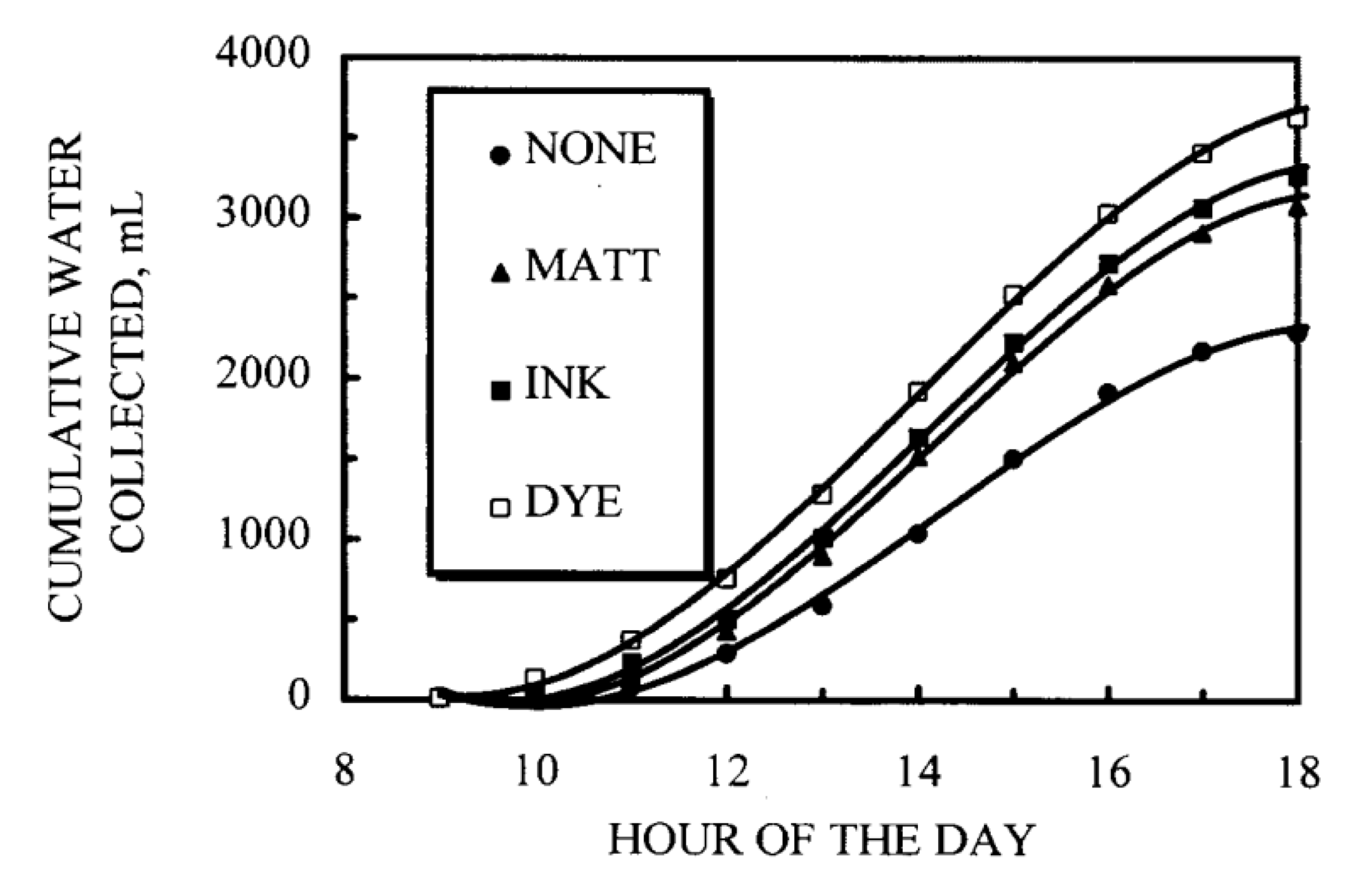
Akash et al. [91] tested the impact of using black rubber mat, black ink, and black dye on the distillate of the solar distiller, and the experimental results revealed that these materials improved the output distillate by 38%, 45%, and 60%, respectively. Thus, the black dye obtained the best enhancement of solar still productivity, as shown in Figure 62.
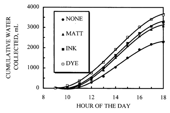
Figure 62.
Total solar still productivity when using various absorbing materials [91].
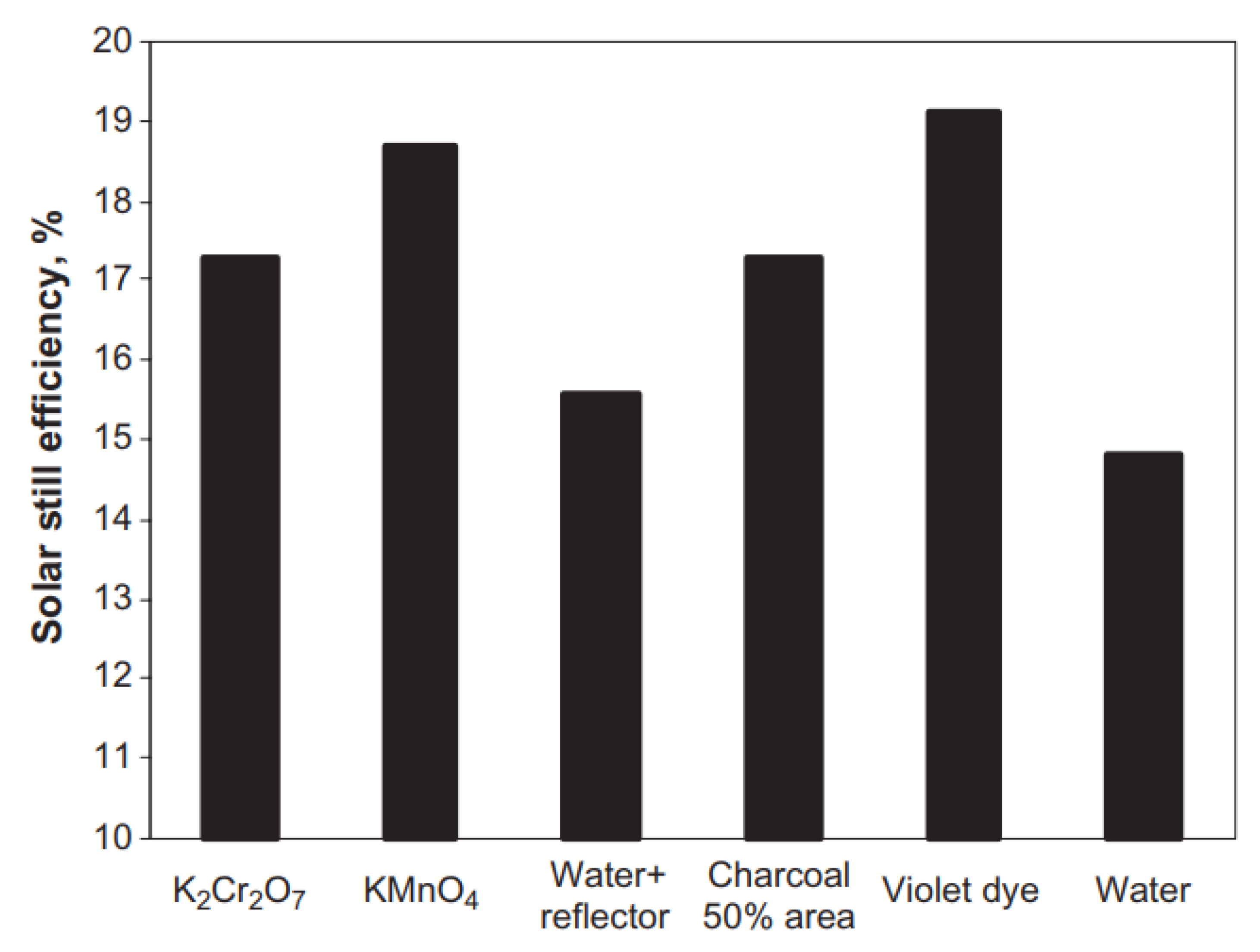
Moreover, Nijmeh et al. [92] studied experimentally and theoretically the effect of using the materials of dissolved salts (potassium permanganate: KMnO4 and potassium dichromate: K2Cr2O7), violet dye, and charcoal on the performance of the solar still. The authors revealed a significant enhancement in the solar distiller efficiency by using these absorbing materials as shown in Figure 63. Additionally, the authors concluded that the best choices of absorbing materials were the violet dye and KMnO4 (50 mg/L), where they increased the distillate by 29% and 2%, respectively.
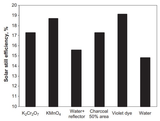
Figure 63.
The solar distiller efficiency at the various studied absorbing materials [92].
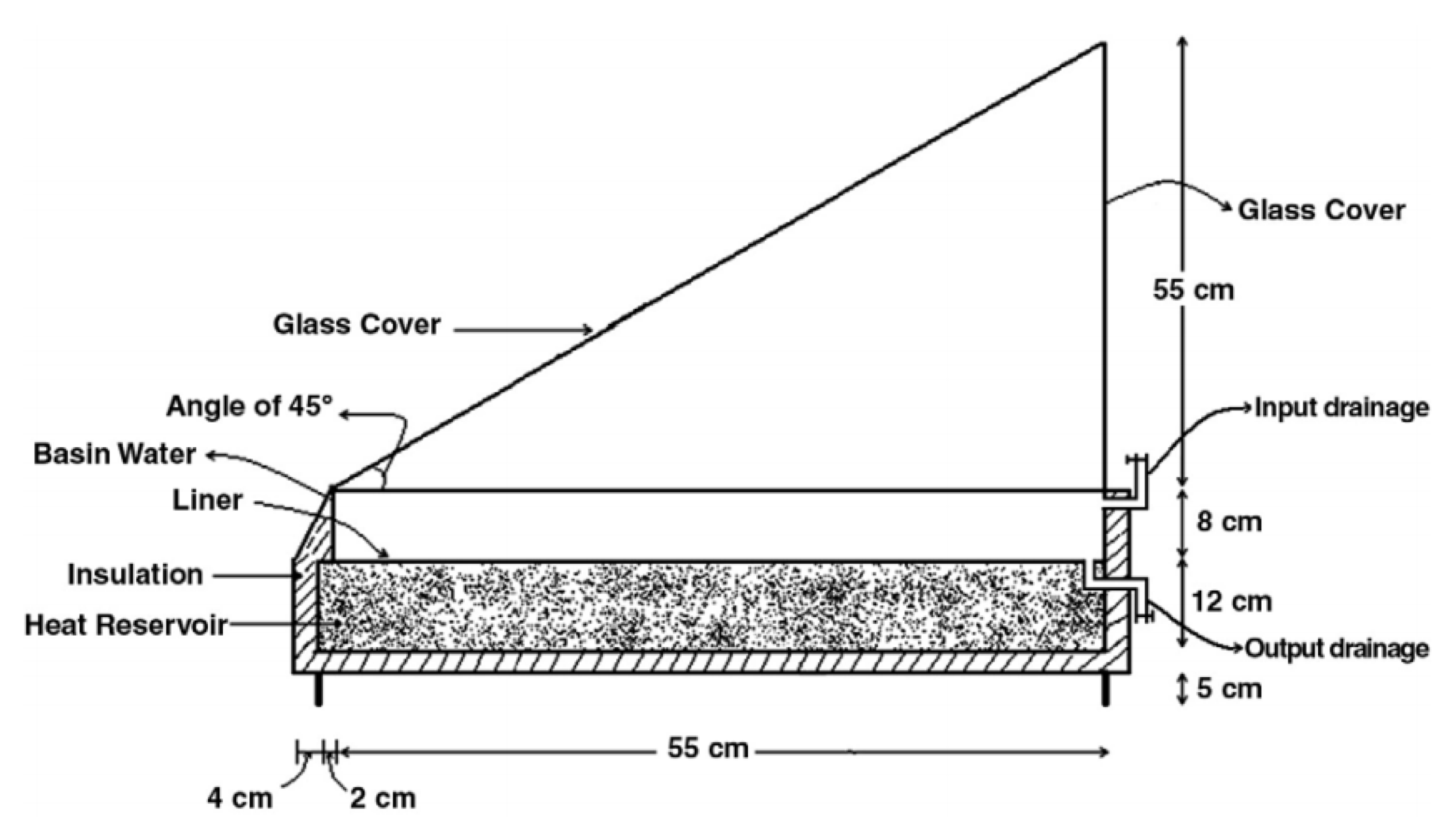
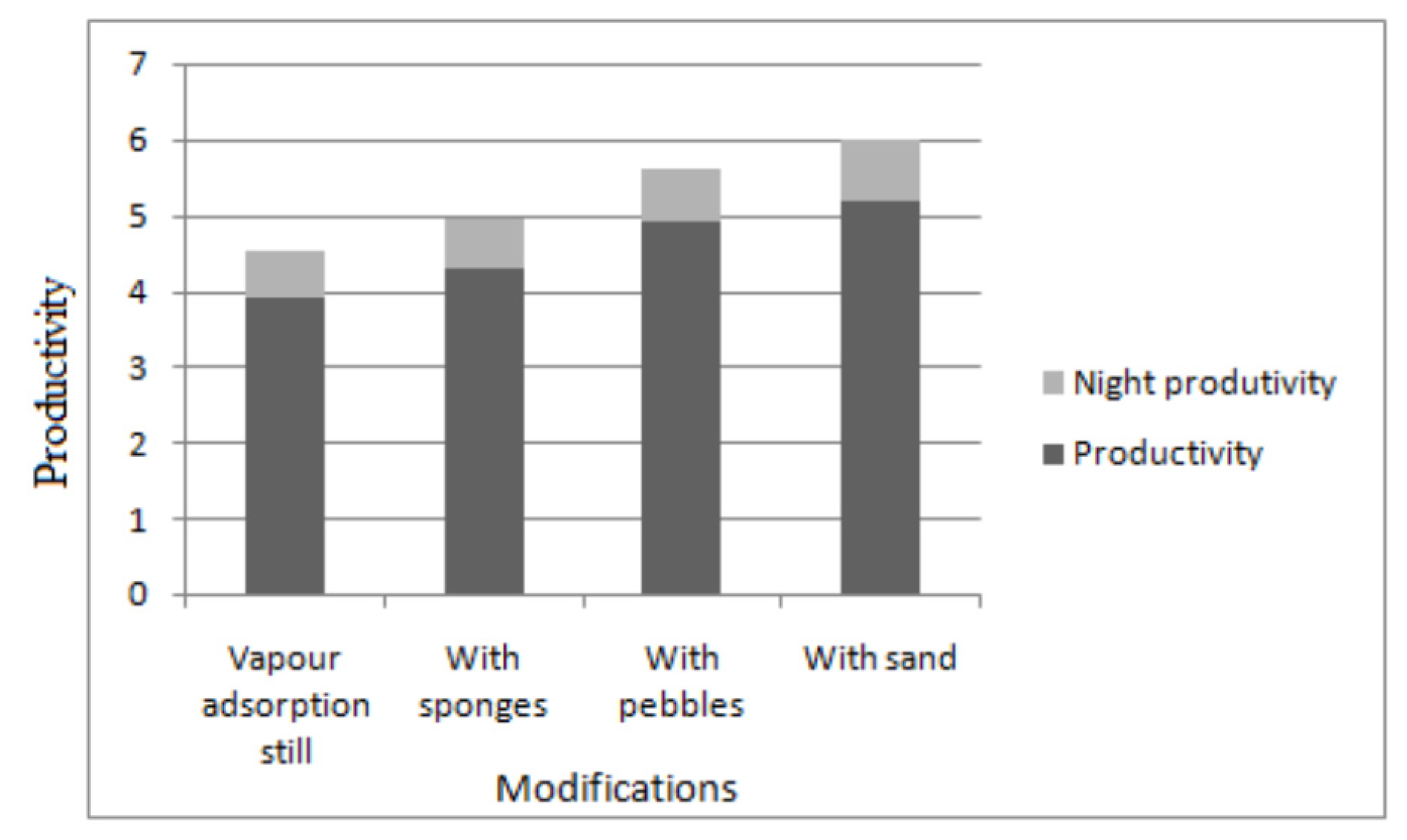
Furthermore, Tabrizi and Sharak [93] tested the effect of providing the sand over the basin liner to work as a heat absorbing and storage material (heat reservoir), as obtained in Figure 64. A gap of 12 cm was filled by the sand (ρ = 2.5 g/cm3) to work as the heat reservoir. The results revealed that the freshwater distillate was improved by 75% as a result of using the sand bed, where the distillate of the conventional and modified solar distillers was 1700 cm3/m2 and 3000 cm3/m2, respectively. In addition, Srithar [94] utilized the absorbing materials of sponge, pebble, and sand to augment the solar distiller productivity. Results revealed that the sand provided the best performance of the solar distiller as drawn in Figure 65. The synergetic effect of using both sand and sponge introduced an enhancement of productivity of 32.32% as compared to that without the absorbing materials.
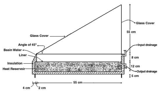
Figure 64.
Schematic of the studied system [93].
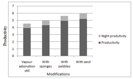
Figure 65.
The productivity of the solar still when using different absorbing materials through the day [94].
The synergetic effect of using both sand and sponge introduced an enhancement of productivity of 32.32% as compared to that without the absorbing materials. This study had a merit of the availability and cheapness of the sand as a heat storing material, which makes it available for anyone to use.
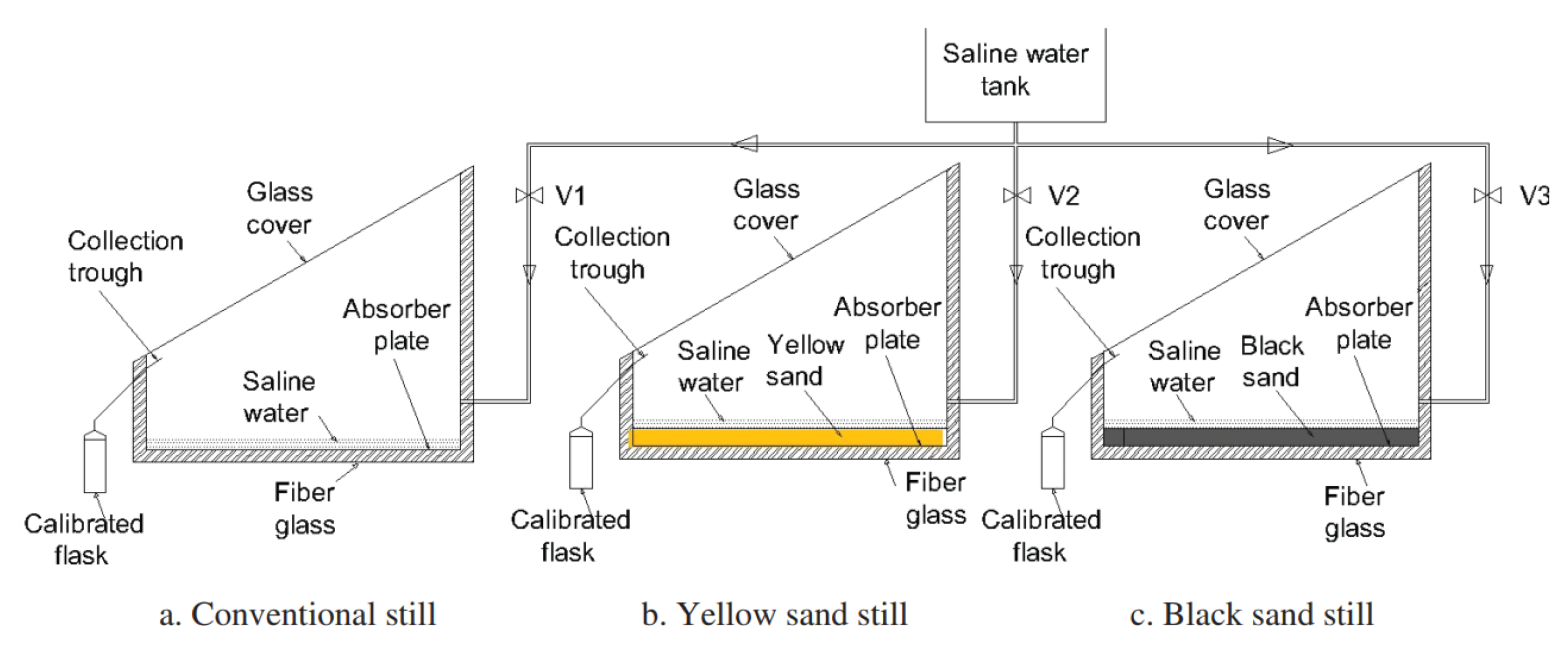
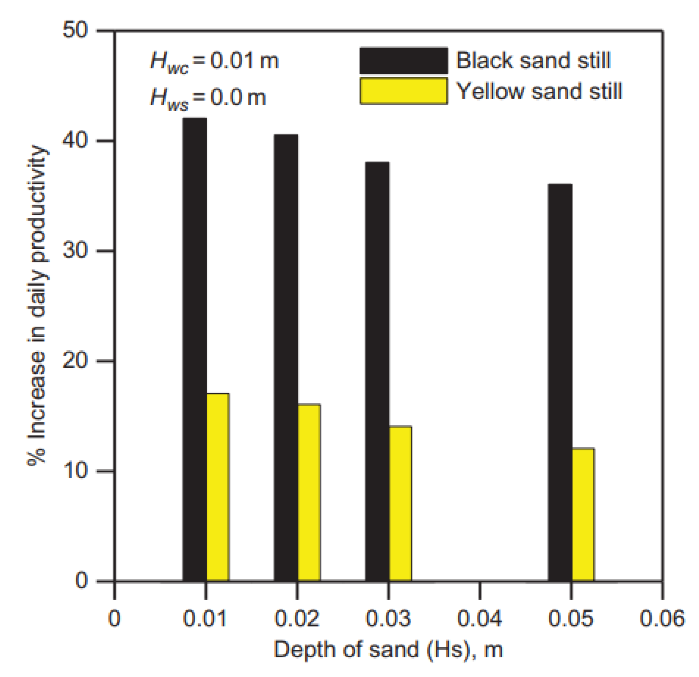
Omara and Kabeel [95] theoretically and experimentally investigated several parameters on a sand beds solar still, Figure 66. These parameters were different types of sand (black and yellow), sandy bed height (1, 2, 3, and 5 cm), and water height above sandy bed level (0, 1, 2, and 3 cm). Their results indicate that the black sand still provided the greatest productivity under all conditions as illustrated in Figure 67. The average daily distillate was improved by 42% and 17% when using the black and yellow sands, respectively.
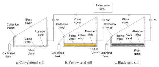
Figure 66.
Schematic of the experimental setup [95].
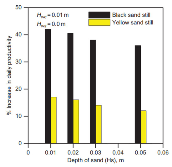
Figure 67.
The daily distillate yield of solar still for black and yellow sands at different sand depths [95].
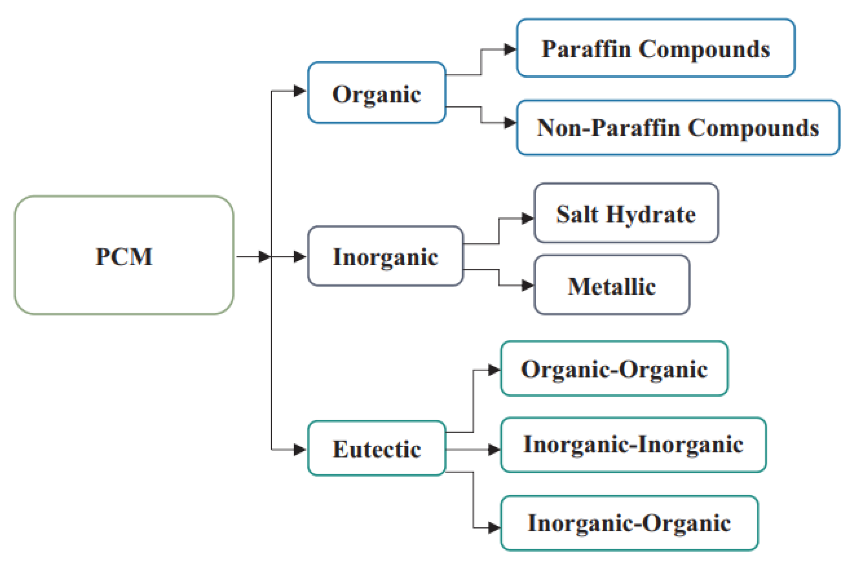
On the other hand, the phase change materials (PCMs) or the latent heat storage materials are melted and solidified at a specific temperature. As a result, these materials are capable of storing and releasing a substantial amount of latent energy. Changing the phase of the material from solid to liquid (melting) makes the PCM stores specific amount of heat energy. Additionally, changing the phase of the material from liquid to solid (solidification) makes the PCM releases the same amount of stored heat energy [96]. PCMs can be categorized as organic, inorganic, and eutectic as illustrated with ore details in Figure 68.
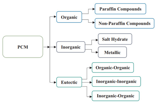
Figure 68.
Characterization of PCMs [96].
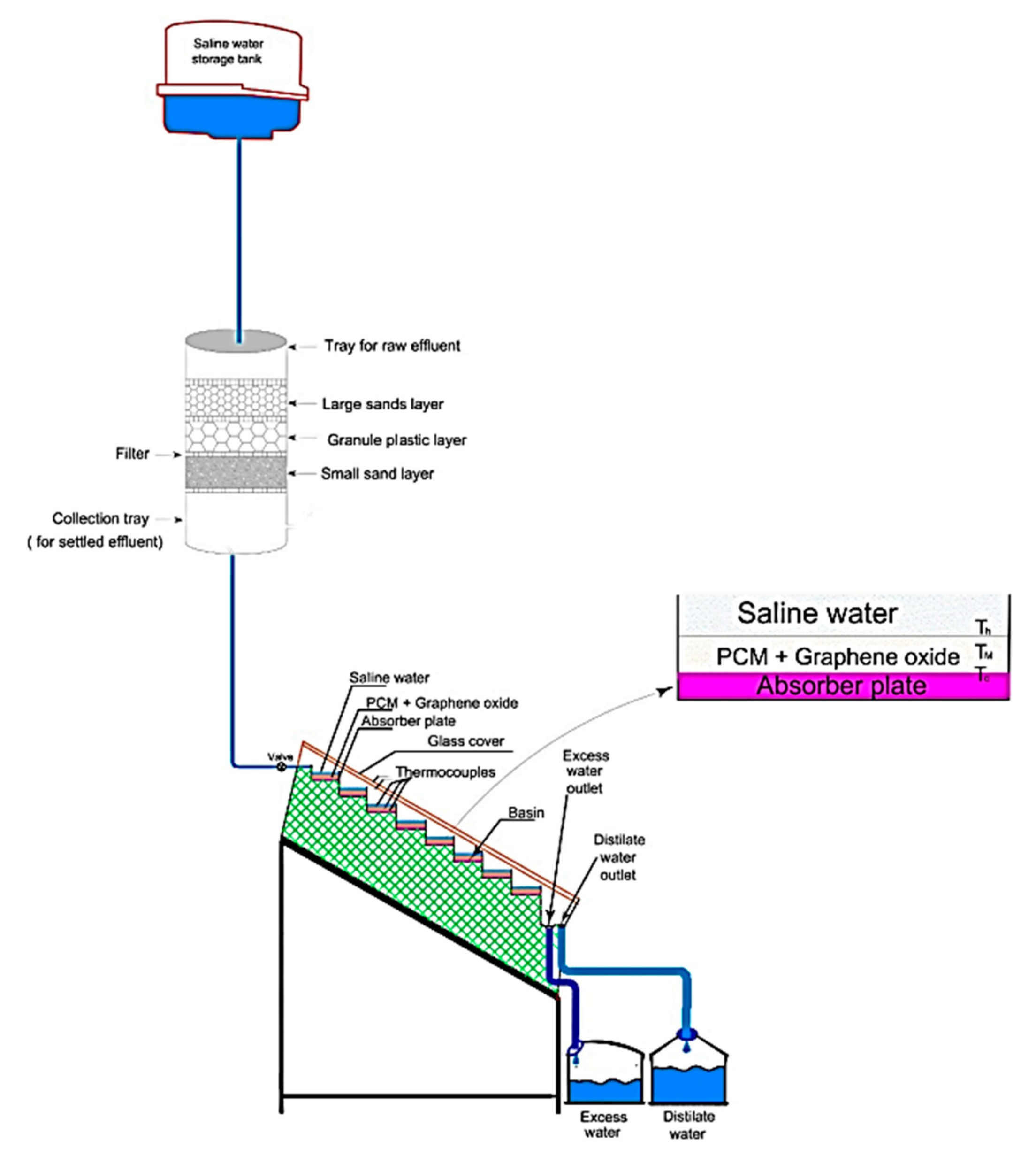
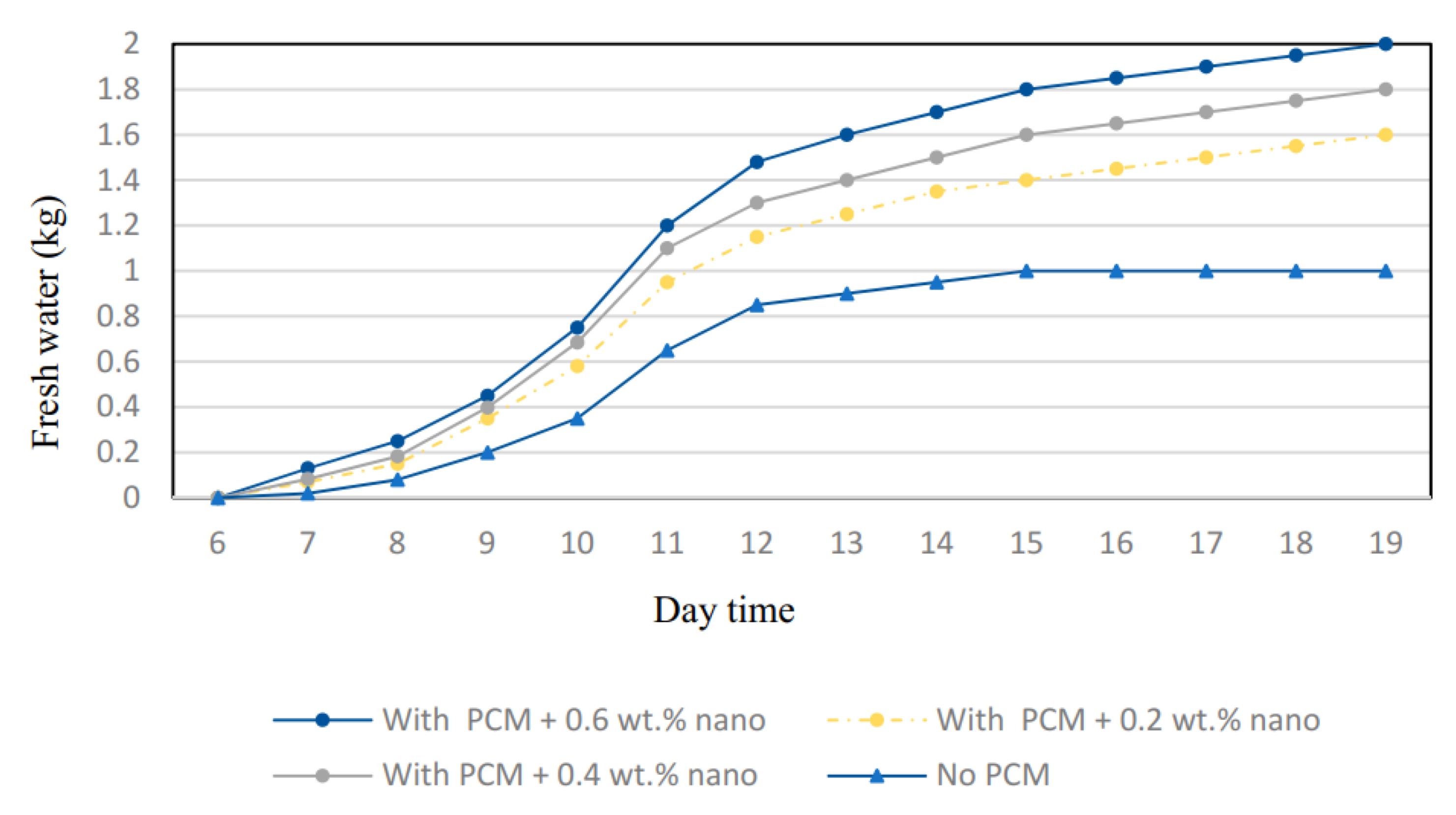
Furthermore, Safaei et al. [97] mixed the graphene oxide with the paraffin wax at various concentrations (0.2, 0.4, and 0.6 wt.%) to augment the solar still productivity, as shown in Figure 69. Their results revealed that the solar distiller productivity was better when using the graphene oxide with the paraffin wax at 0.6 wt.% compared to that of either lower concentrations of graphene oxide or without PCM, as presented in Figure 70. This is due to the synergetic effect of the merits of the PCM material and nanoparticles. The solar distiller performance was enhanced by 25% when using PCM and graphene oxide nanoparticles compared to that with PCM only.
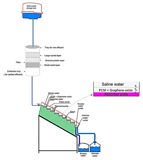
Figure 69.
Schematic of the tested solar distiller [97].
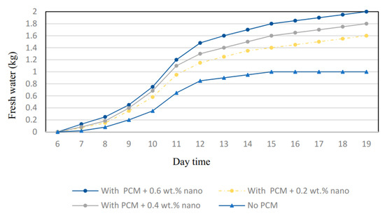
Figure 70.
Solar still distillate with and without PCM and nano-PCMs [97].
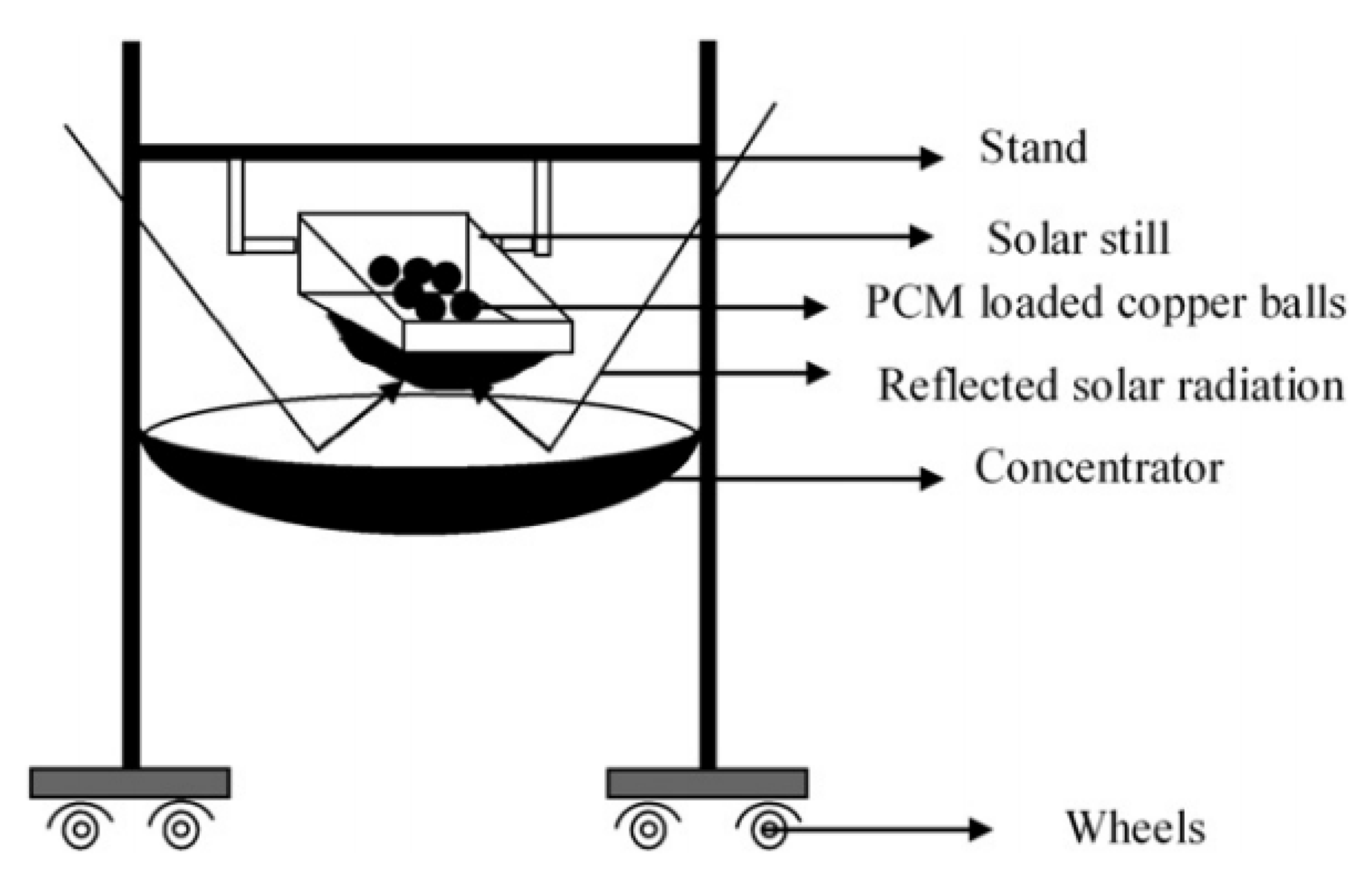
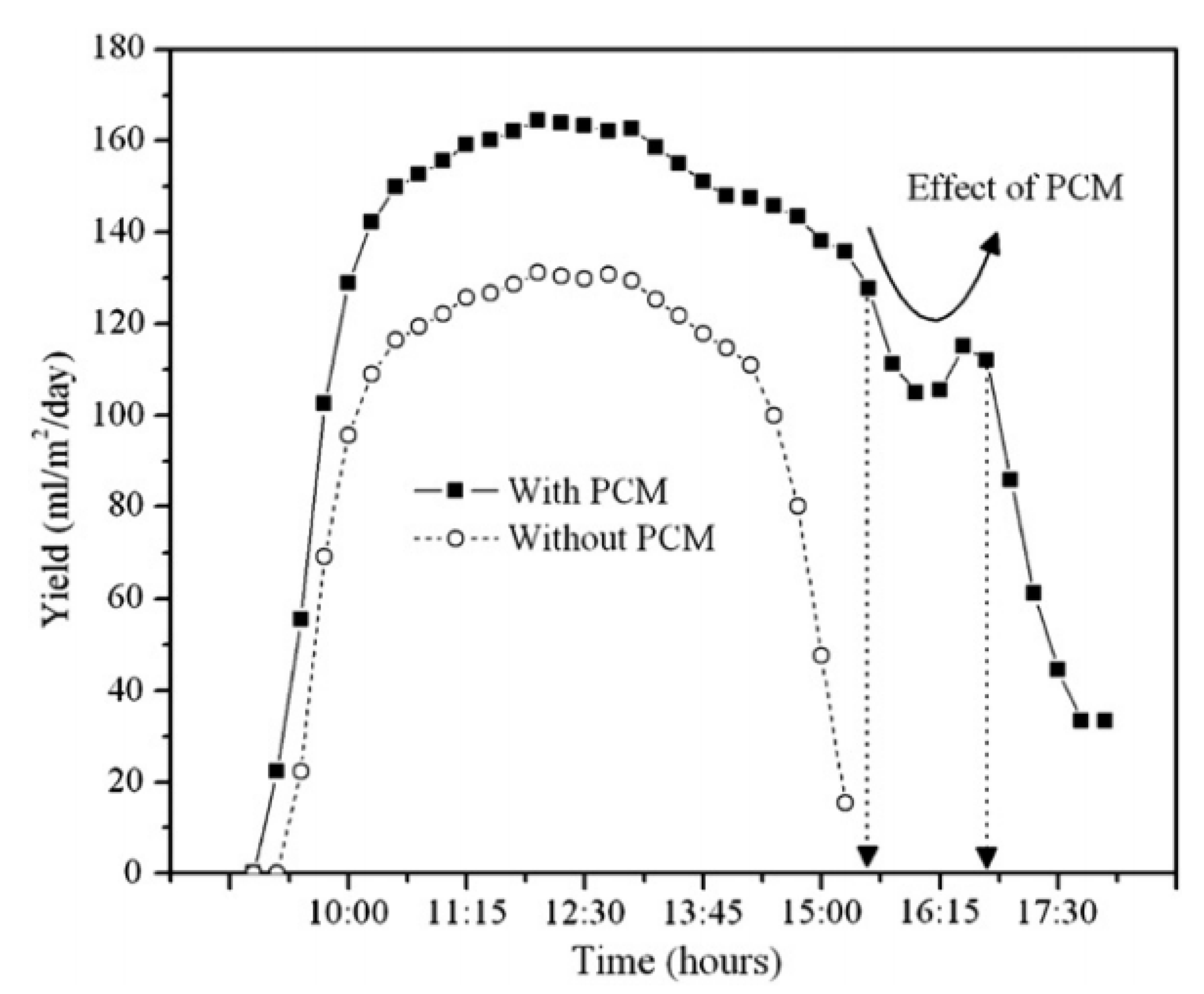
Arunkumar et al. [98] tested the effect of using the PCM with hemispherical solar distiller placed above a concentrator, as shown in Figure 71. The authors obtained that the PCM had a significant role of improving the solar distiller productivity as illustrated in Figure 72. As a result, using the PCM increased the distillate of the concentrator-coupled hemispherical solar distiller from 3520 to 4460 mL/m2.day with an enhancement of 26%.
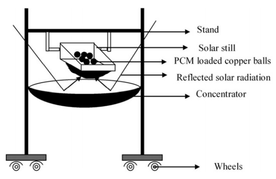
Figure 71.
Schematic of a concentrator with a hemispherical solar distiller [98].
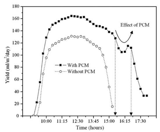
Figure 72.
Effect of PCM on the hourly distillate of the solar distiller [98].
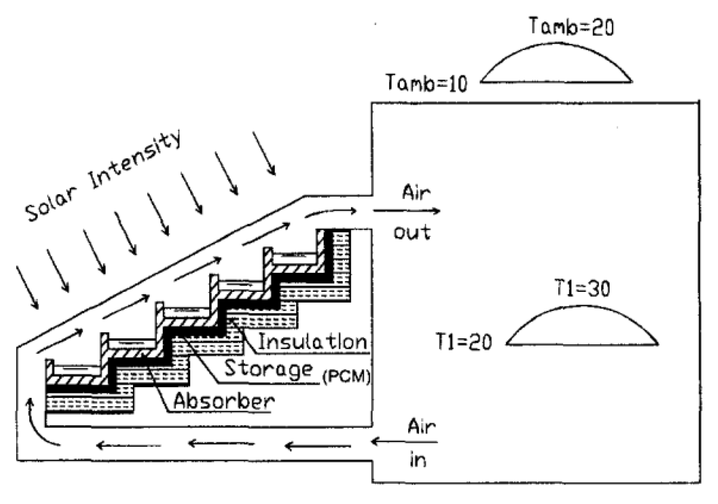
Radhwan [99] performed experiments on the performance of stepped distiller with latent heat thermal energy storage (LHTESS), as shown in Figure 73. Gap slabs were filled by paraffin wax to work as PCM. The experimental results revealed that the thermal efficiency of the system with its proposed configuration was reduced from 61% without LHTESS to 57% with LHTESS.
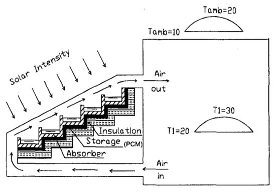
Figure 73.
Scheme of the stepped solar still with built-in latent heat thermal energy storage [99].
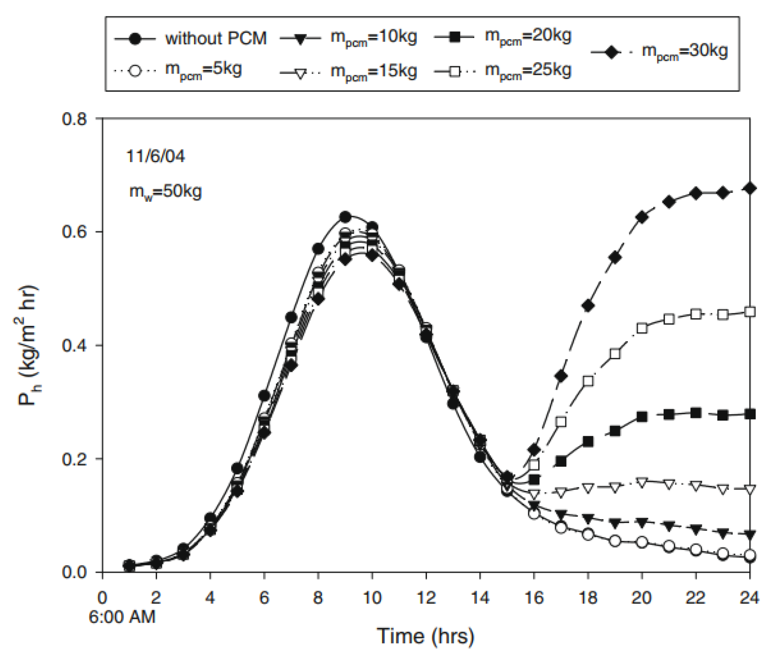
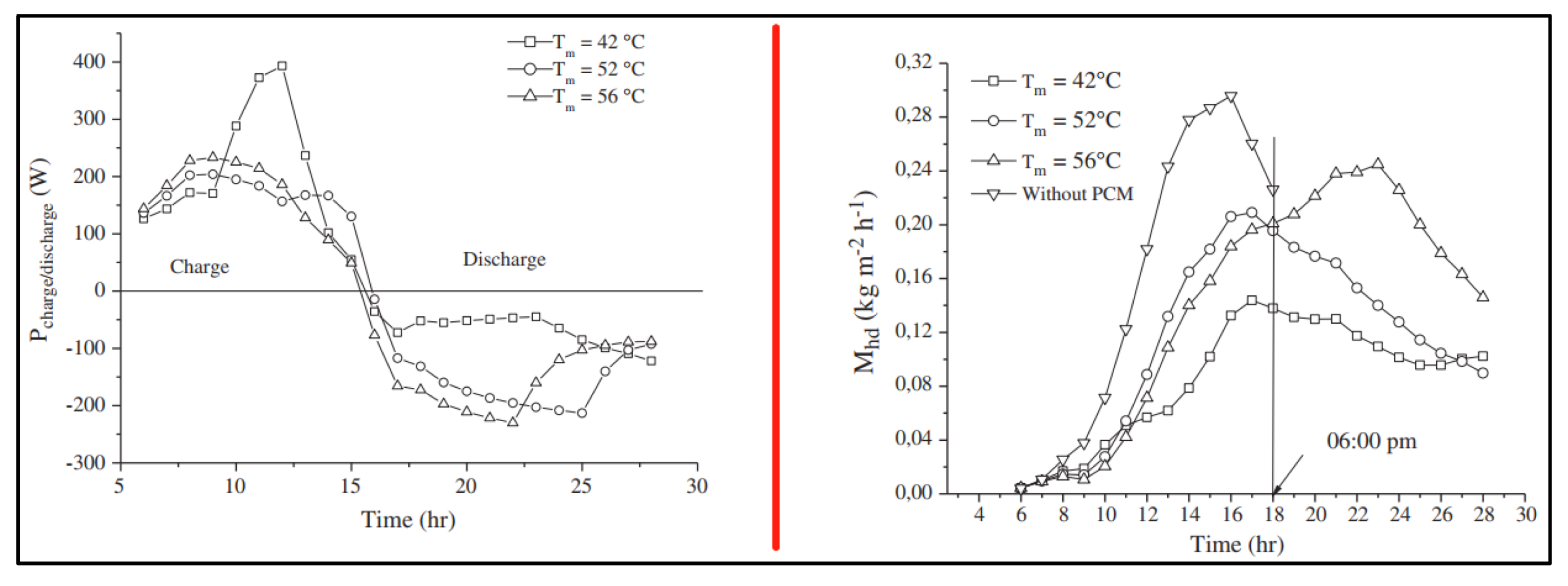
Moreover, El-Sebaii et al. [100] investigated numerically the effect of using a PCM (stearic acid) layer under the basin liner of the solar distiller to improve its performance. The authors found that, as shown in Figure 74, the productivity of the solar distiller was inversely proportional to the mass of the PCM during the daytime. Whereas, during the nighttime, the productivity of the solar distiller was proportional to the mass of the PCM. Consequently, the PCM augmented the solar distiller yield from 4.998 L/m2.day for the distiller without PCM to 9.005 L/m2.day for the distiller with PCM. Ansari et al. [101] concluded that the PCM should be selected for desalination purposes based on the highest temperature that basin water can attain, and it should be close to the melting point of the PCM material, as illustrated in Figure 75.
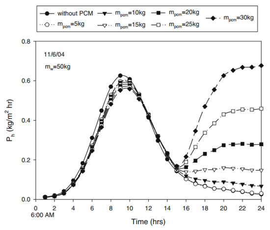
Figure 74.
Hourly distillate of the solar distiller with and without PCM at various PCM masses [100].
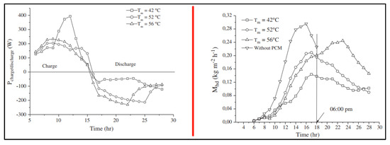
Figure 75.
Effect of PCM type on the hourly variations of charge and the discharge and hourly distillate [101].
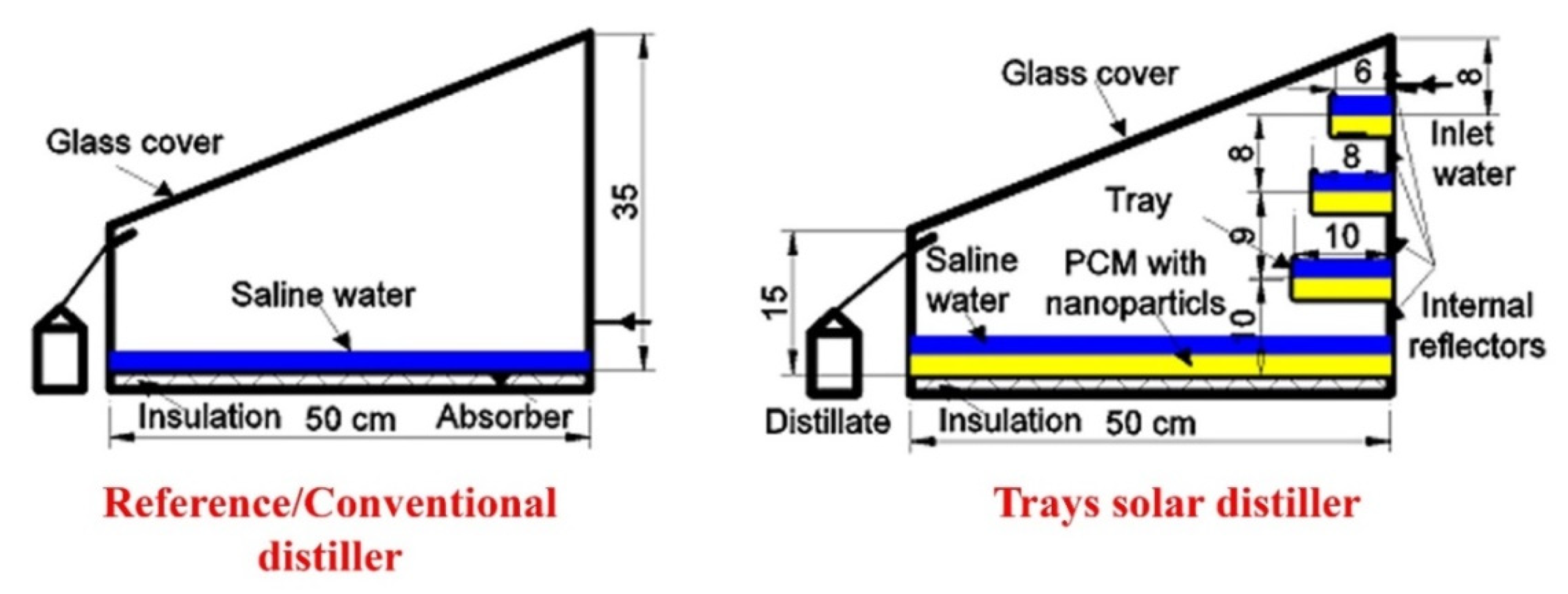
Recently, Abdullah et al. [60] used the mixture of paraffin wax mixed with CuO nanoparticles as a PCM to improve the performance of the solar distiller shown in Figure 76. Their results revealed that the mixture of paraffin wax and CuO nanoparticles improved the distiller productivity significantly as obtained in Figure 77. The authors increased the solar still productivity by 108% when using the reflectors, nano coating, and PCM with CuO nanoparticles.
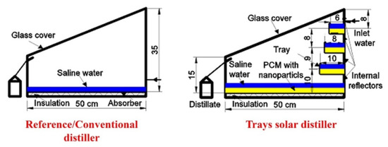
Figure 76.
Scheme of the trays solar distiller with PCM [60].
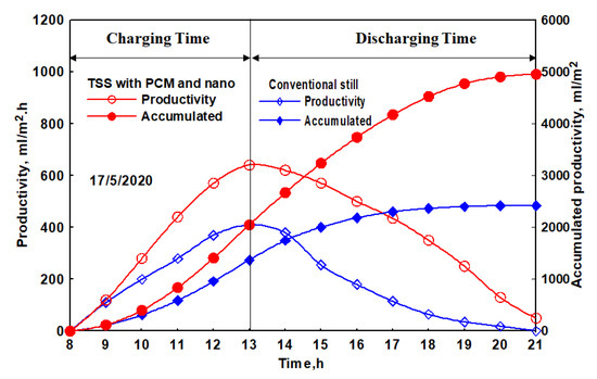
Figure 77.
Distillate water of the trays solar still with and without PCM [60].
4.3.5. Difference between the Glass and Basin Water Temperatures
Murugavel et al. [102] investigated the performance of single-basin double-slope solar still with thin layer of water, as illustrated in Figure 78. The authors also used cotton cloth, jute cloth, sponge sheet, washed natural rock, and quartzite rock as porous and spread materials inside the distiller. The results revealed that the cotton cloth provided the best water yield. Furthermore, the authors reported that the productivity of the solar still is a function of the temperature difference between the water and glass cover. The water yield could be raised with increasing the temperature difference between the water and glass, as shown in Figure 79.
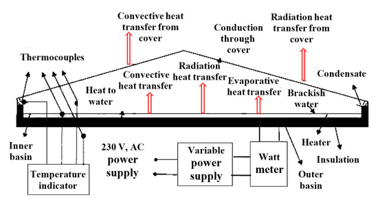
Figure 78.
Double slope single basin solar still [102].
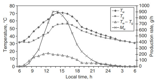
Figure 79.
Temperatures and productivity changes for the still with quartzite rock as basin material [102].
Moreover, Patel and Kumar [103] studied the performance of the double slope solar still under different water depths and air speeds. The authors reported that the distiller yield was improved with increasing the wind speed, cooling the glass covers, and decreasing the water depth. Thus, increasing the difference between the water and glass temperatures is a main reason for increasing the distiller productivity. Abu-Arabi et al. [104] confirmed the same conclusion of improving the productivity of the solar still when decreasing the glass temperature via cooling it. Moreover, Janarthanan et al. [105] used the flowing water over the glass to lower its temperature and increase the temperature difference between the water and glass. This improved the productivity significantly. As a result, increasing the temperature difference between the water and glass increases the freshwater productivity of the solar still, as illustrated in Figure 80.
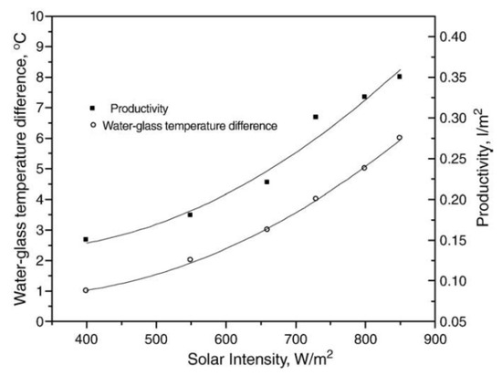
Figure 80.
Impact of solar irradiance and water-glass temperature difference on the solar still productivity [94].
4.3.6. Capability of Hybrid Systems
Abdullah et al. [106] linked the humidification–dehumidification unit with wick six solar distillers and tested the effect of various packing materials and water flow rates on the performance of the hybrid system, Figure 81. The authors utilized the exhaust rejected hot water from the HDH unit to be a supply water for the solar distillers. This arrangement enabled the solar distillers to operate at the daytime as well as the nighttime. It provided high productivity through the day, as illustrated in Figure 82. As a result, the introduced amendments significantly improved the performance of the wick solar distillers, HDH, and hybrid system.
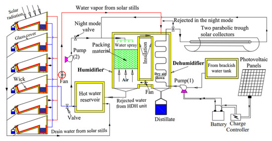
Figure 81.
Schematic of the HDH unit connected to six solar distillers [106].
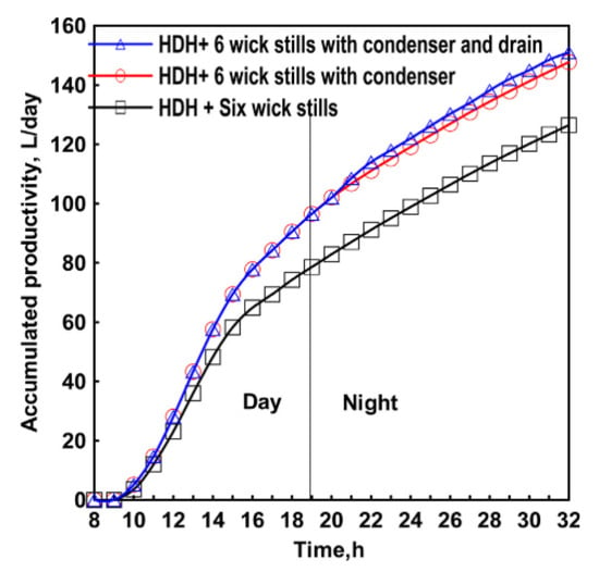
Figure 82.
The total distillate of the wick stills and HDH through the day and night times [106].
5. Conclusions
This current study focuses on comprehensively explaining the variables that affect the performance of solar stills. These factors are categorized into three main and general titles: climatic, design, and operating factors. The climatic factors include solar radiation, ambient temperature, air speed, and dusty and cloudy weather. The design factors include the evaporative and exposure surface areas, glazing cover material, inclination, and thickness, distiller material, and of insulating material and thickness. Whereas, the operating parameters have the water temperature, feed water temperature, applying vacuum, temperature difference between water and glass cover, and hybrid systems. Based on the comprehensive survey on all factors, the following conclusions can be drawn:
- The main strongest affecting parameter on the solar distiller performance is the solar radiation. It has been verified in countless studies and publications that the higher the radiation intensity, the higher the productivity of solar stills. As a result, several amendments were introduced to increase the incident solar radiation on the basin water;
- Lowering the basin water depth improved the freshwater productivity of the solar distiller. It was concluded that the best water depth inside the solar distillers should be around 1–3 cm. In addition, it can be concluded that the daytime productivity of the distiller is inversely proportional to the basin water depth, while the nighttime productivity is proportional to the basin water depth;
- The ambient temperature affects slightly the solar distiller performance. The efficiency of the solar still is marginally improved with increasing the surrounding air temperature;
- Additionally, the surrounding air speed influences on the thermal performance of the solar distiller. Some publications state that the distillate of the solar distiller is augmented with increasing the air speed until a certain value, and it declines after that critical value;
- Raising the feed water temperature improves the solar distiller yield. Numerous techniques such as the solar water heater, mini solar pond, shallow solar pond, and solar collectors were developed to achieve this goal. Moreover, this can be achieved by linking two desalination systems together such as the solar stills and HDH, and the reject water of the HDH is used to warm the feed water of the solar stills;
- The second most significant parameter that affects the performance of solar stills, after solar radiation, is the difference between the water and glass temperatures. The greater this difference is, the higher the solar still productivity is, and the better the distiller performance is. This can be achieved by raising the basin water temperature, decreasing the glass temperature, or both;
- Furthermore, the evaporative and exposure surface areas have a vital role on determining how much the solar distiller performance can be improved. The larger the evaporative and exposure surface areas, the better the distiller performance;
- The glass cover tilt angle is also a significant factor that influences the solar still productivity up to great extent. Many papers have stated that the tilt angle must be ±10° of the latitude of the place of experiments;
- Applying vacuum inside the solar is still able to increase the output distillate and thermal efficiency of the solar still remarkably;
- Using the heat storage materials, dyes, and phase change materials is a good choice to improve the thermal performance of the solar distiller. The literature reported that the paraffin wax and stearic acid have superior matching properties that enhance the soar still performance significantly. The solar distiller can still work during the nighttime and sun absent when using these materials;
- Finally, the shape of the solar still is chosen based on the latitude of the experiments’ place, where the single slope distiller is preferable when the latitude is more than 20°, and the double slope distiller is preferable when the latitude is lower than 20°. This configuration eliminates the energy loss from the glazing of the distiller and increases its productivity.
6. Recommendations
According to the aforementioned results and explanations, the following points can be suggested to be investigated:
- Fabricating an automatic mechanism to clean the dust accrued over the glass cover surface of the solar distiller. This will help increase the incident solar radiation on the solar still liner. The performance of the solar distiller should be tested when installing this cleaning mechanism.
- Similar to the sun tracking systems, a tracking system for the optimum tilt angle of the glass cover shall be proposed and investigated. This will help make the glass cover normal to the direct solar beams, which increases the solar energy input to the solar still basin. Hence, the evaporation and condensation rates will be increased. As a result, the solar still productivity is thought to be improved.
- New materials for the basin solar still shall be introduced, taking into consideration the heat transfer characteristics of these materials. This will lead to improving the heat transfer between the basin water and basin liner, hence the water temperature is thought to be increased. Therefore, the solar distiller distillate would be improved.
- Providing air conditioning to the glass cover with an integrated air conditioning system. This will avoid the loss of the incident solar radiation due to the cooling of glass cover by water because of the film created on the glass surface. Additionally, this mechanism will increase the temperature difference between the basin water and glass cover. As a result, the evaporation and condensation quantities will be augmented. Hence, the solar still productivity will be enhanced.
Author Contributions
Conceptualization, F.A.E. and Z.M.O.; methodology, A.A. and H.S.M.; validation, A.B.; formal analysis, H.A.D.; investigation, S.A.M.; resources, W.H.A.; writing—original draft preparation, F.A.E.; writing—review and editing, F.A.E. and Z.M.O.; visualization, A.A.E.; supervision, F.A.E. and Z.M.O.; funding acquisition, T.Y. All authors have read and agreed to the published version of the manuscript.
Funding
This research received no external funding.
Informed Consent Statement
Not applicable.
Data Availability Statement
Not applicable.
Conflicts of Interest
The authors declare no conflict of interest.
Abbreviations
| Symbol | Description |
| ED | Electrodialysis |
| EDR | Electrodialysis reversal |
| HDH | Humidification-dehumidification |
| HF | Hyperfiltration |
| MED | Multi-effect distillation |
| MF | Microfiltration |
| MSF | Multi-stage flash |
| NF | Nanofiltration |
| PCM | Phase change material |
| ppm | Particle per million |
| RO | Reverse osmosis |
| SS | Solar still |
| SSD | Solar still distillation |
| TDS | Total dissolved solids |
| UF | Ultrafiltration |
| VCD | Vapor-compression distillation |
| VD | Vacuum distillation |
Nomenclatures
| Symbol | Description |
| Ag | Glass area |
| Exoutput | Daily overall exergy gain |
| Pg | Partial pressure of glass |
| Pw | Partial pressure of water |
| Ta | Air temperature |
| Tg | Glass temperature |
| Asun | Sun temperature |
| Tw | Water temperature |
| hc.w−g | Water-glass convective heat transfer coefficient |
| he,w−g | Water-glass evaporative heat transfer coefficient |
| hfg | Vaporization latent heat |
| Hourly distillate | |
| ηex | Exergy efficiency |
| ηd | Daily thermal efficiency |
| A | System area |
| I | Daily average solar radiation |
References
- Tiwari, G.N.; Sahota, L. Advanced Solar-Distillation Systems: Basic Principles, Thermal Modeling, and Its Application; Springer: Berlin/Heidelberg, Germany, 2017. [Google Scholar]
- Essa, F.A. Thermal Desalination Systems: From Traditionality to Modernity and Development; Distillation Processes—From Conventional to Reactive Distillation Modeling, Simulation and Optimization; Steffen, D., Ed.; IntechOpen: London, UK, 2022; p. 23. [Google Scholar]
- Kumar, M.; Puri, A. A review of permissible limits of drinking water. Indian J. Occup. Environ. Med. 2012, 16, 40. [Google Scholar] [PubMed]
- Zhou, J.-Q.; Li, L.; Fu, C.; Wang, J.; Fu, P.; Kong, C.-P.; Bai, F.-Q.; Eglitis, R.I.; Zhang, H.-X.; Jia, R. A novel TC 3 N and seawater desalination. Nanoscale 2020, 12, 5055–5066. [Google Scholar] [CrossRef] [PubMed]
- Abdullah, A.; Essa, F.; Omara, Z.; Rashid, Y.; Hadj-Taieb, L.; Abdelaziz, G.; Kabeel, A. Rotating-drum solar still with enhanced evaporation and condensation techniques: Comprehensive study. Energy Convers. Manag. 2019, 199, 112024. [Google Scholar] [CrossRef]
- Kabeel, A.E.; Omara, Z.M.; Essa, F.A. Numerical investigation of modified solar still using nanofluids and external condenser. J. Taiwan Inst. Chem. Eng. 2017, 75, 77–86. [Google Scholar] [CrossRef]
- Malaeb, L.; Aboughali, K.; Ayoub, G.M. Modeling of a modified solar still system with enhanced productivity. Sol. Energy 2016, 125, 360–372. [Google Scholar] [CrossRef]
- Elango, C.; Gunasekaran, N.; Sampathkumar, K. Thermal models of solar still—A comprehensive review. Renew. Sustain. Energy Rev. 2015, 47, 856–911. [Google Scholar] [CrossRef]
- Tiwari, G.N.; Mishra, A.K.; Meraj, M.; Ahmad, A.; Khan, M.E. Effect of shape of condensing cover on energy and exergy analysis of a PVT-CPC active solar distillation system. Sol. Energy 2020, 205, 113–125. [Google Scholar] [CrossRef]
- Abdelkader, M.; Nafy, A.S.; Abdelmotalip, A.; Mabrouk, A. Experimental evaluation of solar still mathematical models. In Proceedings of the Fourth International Water Technology Conference, Alexandria, Egypt, 23–25 April 1999. [Google Scholar]
- Nafey, A.S.; Abdelkader, M.; Abdelmotalip, A.; Mabrouk, A. Parameters affecting solar still productivity. Energy Convers. Manag. 2000, 41, 1797–1809. [Google Scholar] [CrossRef]
- Almuhanna, E.A. Evaluation of Single Slop Solar Still Integrated with Evaporative Cooling System for Brackish Water Desalination. J. Agric. Sci. 2014, 6, 48. [Google Scholar] [CrossRef]
- Aburideh, H.; Deliou, A.; Abbad, B.; Alaoui, F.; Tassalit, D.; Tigrine, Z. An Experimental Study of a Solar Still: Application on the sea water desalination of Fouka. Procedia Eng. 2012, 33, 475–484. [Google Scholar] [CrossRef]
- Morse, R.; Read, W. A rational basis for the engineering development of a solar still. Sol. Energy 1968, 12, 5–17. [Google Scholar] [CrossRef]
- Rahbar, N.; Esfahani, J.A. Experimental study of a novel portable solar still by utilizing the heatpipe and thermoelectric module. Desalination 2012, 284, 55–61. [Google Scholar] [CrossRef]
- Okeke, C.; Egarievwe, S.; Animalu, A. Effects of coal and charcoal on solar-still performance. Energy 1990, 15, 1071–1073. [Google Scholar] [CrossRef]
- Kamal, W. A theoretical and experimental study of the basin-type solar still under the arabian gulf climatic conditions. Sol. Wind Technol. 1988, 5, 147–157. [Google Scholar] [CrossRef]
- Al-Hinai, H.; Al-Nassri, M.; Jubran, B. Effect of climatic, design and operational parameters on the yield of a simple solar still. Energy Convers. Manag. 2002, 43, 1639–1650. [Google Scholar] [CrossRef]
- Malik, M.A.; Tiwari, G.N.; Kumar, A.; Sodha, M. Solar Distillation: A Practical Study of a Wide Range of Stills and Their Optimum Design, Construction, and Performance; Pergamon Press: Oxford, UK, 1982. [Google Scholar]
- Alheefi, T. Experimental and Analytical Study of Water Production of Solar Still; Brunel University London: Uxbridge, UK, 2019. [Google Scholar]
- Essa, F.A.; Abdullah, A.S.; Omara, Z.M. Rotating discs solar still: New mechanism of desalination. J. Clean. Prod. 2020, 275, 123200. [Google Scholar] [CrossRef]
- Soliman, S. Effect of wind on solar distillation. Sol. Energy 1972, 13, 403–415. [Google Scholar] [CrossRef]
- El-Sebaii, A. Effect of wind speed on active and passive solar stills. Energy Convers. Manag. 2004, 45, 1187–1204. [Google Scholar] [CrossRef]
- El-Sebaii, A. On effect of wind speed on passive solar still performance based on inner/outer surface temperatures of the glass cover. Energy 2011, 36, 4943–4949. [Google Scholar] [CrossRef]
- Reddy, R.; Reddy, K. Upward heat flow analysis in basin type solar still. J. Min. Metall. B Metall. 2009, 45, 121–126. [Google Scholar]
- Muftah, A.F.; Alghoul, M.; Fudholi, A.; Abdul-Majeed, M.; Sopian, K. Factors affecting basin type solar still productivity: A detailed review. Renew. Sustain. Energy Rev. 2014, 32, 430–447. [Google Scholar] [CrossRef]
- Hegazy, A.A. Effect of dust accumulation on solar transmittance through glass covers of plate-type collectors. Renew. Energy 2001, 22, 525–540. [Google Scholar] [CrossRef]
- Hottel, H.; Woertz, B. The Performance of Flat-Plate Solar Heat Collectors; Routledge: London, UK, 2018. [Google Scholar]
- El-Nashar, A.M. The effect of dust accumulation on the performance of evacuated tube collectors. Sol. Energy 1994, 53, 105–115. [Google Scholar] [CrossRef]
- El-Nashar, A.M. Seasonal effect of dust deposition on a field of evacuated tube collectors on the performance of a solar desalination plant. Desalination 2009, 239, 66–81. [Google Scholar] [CrossRef]
- Omara, Z.; Hamed, M.H.; Kabeel, A. Performance of finned and corrugated absorbers solar stills under Egyptian conditions. Desalination 2011, 277, 281–287. [Google Scholar] [CrossRef]
- Abdullah, A.S.; Omara, Z.M.; Alarjani, A.; Essa, F.A. Experimental investigation of a new design of drum solar still with reflectors under different conditions. Case Stud. Therm. Eng. 2021, 24, 100850. [Google Scholar] [CrossRef]
- Velmurugan, V.; Gopalakrishnan, M.; Raghu, R.; Srithar, K. Single basin solar still with fin for enhancing productivity. Energy Convers. Manag. 2008, 49, 2602–2608. [Google Scholar] [CrossRef]
- Sakthivel, M.; Shanmugasundaram, S.; Alwarsamy, T. An experimental study on a regenerative solar still with energy storage medium—Jute cloth. Desalination 2010, 264, 24–31. [Google Scholar] [CrossRef]
- Velmurugan, V.; Kumaran, S.S.; Prabhu, N.V.; Srithar, K. Productivity enhancement of stepped solar still: Performance analysis. Therm. Sci. 2008, 12, 153–163. [Google Scholar] [CrossRef]
- Minasian, A.; Al-Karaghouli, A. An improved solar still: The wick-basin type. Energy Convers. Manag. 1995, 36, 213–217. [Google Scholar] [CrossRef]
- Tiwari, A.K.; Tiwari, G. Effect of water depths on heat and mass transfer in a passive solar still: In summer climatic condition. Desalination 2006, 195, 78–94. [Google Scholar] [CrossRef]
- Elango, T.; Murugavel, K.K. The effect of the water depth on the productivity for single and double basin double slope glass solar stills. Desalination 2015, 359, 82–91. [Google Scholar] [CrossRef]
- Khalifa, A.J.N.; Hamood, A.M. On the verification of the effect of water depth on the performance of basin type solar stills. Sol. Energy 2009, 83, 1312–1321. [Google Scholar] [CrossRef]
- Lindblom, J. Solar Thermal Technologies for Seawater Desalination: State of the Art. 2003. Available online: https://www.researchgate.net/publication/228401141_Solar_thermal_technologies_for_seawater_desalination_state_of_the_art (accessed on 6 April 2022).
- Ghoneyem, A.; Ileri, A. Software to analyze solar stills and an experimental study on the effects of the cover. Desalination 1997, 114, 37–44. [Google Scholar] [CrossRef]
- Akash, B.A.; Mohsen, M.S.; Nayfeh, W. Experimental study of the basin type solar still under local climate conditions. Energy Convers. Manag. 2000, 41, 883–890. [Google Scholar] [CrossRef]
- Singh, H.; Tiwari, G. Monthly performance of passive and active solar stills for different Indian climatic conditions. Desalination 2004, 168, 145–150. [Google Scholar] [CrossRef]
- Panchal, H.; Shah, P.K. Investigation on solar stills having floating plates. Int. J. Energy Environ. Eng. 2012, 3, 8. [Google Scholar] [CrossRef]
- Nassef, E.M.; El-Abd, M.Z.; El-Tawil, Y.A. Study of the performance of solar still. In Proceedings of the 2nd International Conference on Energy Systems and Technologies, Cairo, Egypt, 18–21 February 2013. [Google Scholar]
- Essa, F.A.; Abd Elaziz, M.; Elsheikh, A.H. An enhanced productivity prediction model of active solar still using artificial neural network and Harris Hawks optimizer. Appl. Therm. Eng. 2020, 170, 115020. [Google Scholar] [CrossRef]
- Abdullah, A.S.; Essa, F.A.; Omara, Z.M. Effect of different wick materials on solar still performance—A review. Int. J. Ambient Energy 2019, 42, 1055–1082. [Google Scholar] [CrossRef]
- Al-Hassan, G.A.; Algarni, S.A. Exploring of Water Distillation by Single Solar Still Basins. Am. J. Clim. Chang. 2013, 2, 57–61. [Google Scholar] [CrossRef]
- Fath, H.E.S.; El-Samanoudy, M.; Fahmy, K.; Hassabou, A. Thermal-economic analysis and comparison between pyramid-shaped and single-slope solar still configurations. Desalination 2003, 159, 69–79. [Google Scholar] [CrossRef]
- Murugavel, K.K.; Chockalingam, K.K.; Srithar, K. Progresses in improving the effectiveness of the single basin passive solar still. Desalination 2008, 220, 677–686. [Google Scholar] [CrossRef]
- Tiwari, G.; Dimri, V.; Chel, A. Parametric study of an active and passive solar distillation system: Energy and exergy analysis. Desalination 2009, 242, 1–18. [Google Scholar] [CrossRef]
- Martin, C.L.; Goswami, D.Y. Solar Energy Pocket Reference; Earthscan: London, UK, 2005; ISBN 978-1-84407-306-1. [Google Scholar]
- Manokar, A.M.; Murugavel, K.K.; Esakkimuthu, G. Different parameters affecting the rate of evaporation and condensation on passive solar still—A review. Renew. Sustain. Energy Rev. 2014, 38, 309–322. [Google Scholar] [CrossRef]
- Kabeel, A.; Omara, Z.M.; Essa, F.; Abdullah, A.; Arunkumar, T.; Sathyamurthy, R. Augmentation of a solar still distillate yield via absorber plate coated with black nanoparticles. Alex. Eng. J. 2017, 56, 433–438. [Google Scholar] [CrossRef]
- Kabeel, A.E.; Sathyamurthy, R.; Sharshir, S.W.; Muthumanokar, A.; Panchal, H.; Prakash, N.; Prasad, C.; Nandakumar, S.; El Kady, M. Effect of water depth on a novel absorber plate of pyramid solar still coated with TiO2 nano black paint. J. Clean. Prod. 2019, 213, 185–191. [Google Scholar] [CrossRef]
- Sathyamurthy, R.; Balasubramanian, M.; Devarajan, M.; Sharshir, S.W.; Manokar, A.M. Experimental study on enhancing the yield from stepped solar still coated using fumed silica nanoparticle in black paint. Mater. Lett. 2020, 272, 127873. [Google Scholar] [CrossRef]
- Essa, F.A.; Abdullah, A.S.; Omara, Z.M. Improving the performance of tubular solar still using rotating drum—Experimental and theoretical investigation. Process Saf. Environ. Prot. 2021, 148, 579–589. [Google Scholar] [CrossRef]
- Abdullah, A.; Alarjani, A.; Al-Sood, M.A.; Omara, Z.; Kabeel, A.; Essa, F. Rotating-wick solar still with mended evaporation technics: Experimental approach. Alex. Eng. J. 2019, 58, 1449–1459. [Google Scholar] [CrossRef]
- Abdullah, A.S.; Omara, Z.M.; Essa, F.A.; Alarjani, A.; Mansir, I.B.; Amro, M.I. Enhancing the solar still performance using reflectors and sliding-wick belt. Sol. Energy 2021, 214, 268–279. [Google Scholar] [CrossRef]
- Abdullah, A.S.; Essa, F.A.; Bacha, H.B.; Omara, Z.M. Improving the trays solar still performance using reflectors and phase change material with nanoparticles. J. Energy Storage 2020, 31, 101744. [Google Scholar] [CrossRef]
- Essa, F.; Alawee, W.H.; Mohammed, S.A.; Abdullah, A.; Omara, Z. Enhancement of pyramid solar distiller performance using reflectors, cooling cycle, and dangled cords of wicks. Desalination 2021, 506, 115019. [Google Scholar] [CrossRef]
- Alawee, W.H.; Mohammed, S.A.; Dhahad, H.A.; Abdullah, A.; Omara, Z.; Essa, F. Improving the performance of pyramid solar still using rotating four cylinders and three electric heaters. Process Saf. Environ. Prot. 2021, 148, 950–958. [Google Scholar] [CrossRef]
- Rai, S.; Tiwari, G. Single basin solar still coupled with flat plate collector. Energy Convers. Manag. 1983, 23, 145–149. [Google Scholar] [CrossRef]
- Morad, M.; El-Maghawry, H.A.; Wasfy, K.I. Improving the double slope solar still performance by using flat-plate solar collector and cooling glass cover. Desalination 2015, 373, 1–9. [Google Scholar] [CrossRef]
- Khalifa, A.J.N.; Hamood, A.M. Effect of insulation thickness on the productivity of basin type solar stills: An experimental verification under local climate. Energy Convers. Manag. 2009, 50, 2457–2461. [Google Scholar] [CrossRef]
- Tiwari, G.N.; Dimri, V.; Singh, U.; Chel, A.; Sarkar, B. Comparative thermal performance evaluation of an active solar distillation system. Int. J. Energy Res. 2007, 31, 1465–1482. [Google Scholar] [CrossRef]
- Sahoo, B.; Sahoo, N.; Mahanta, P.; Borbora, L.; Kalita, P.; Saha, U. Performance assessment of a solar still using blackened surface and thermocol insulation. Renew. Energy 2008, 33, 1703–1708. [Google Scholar] [CrossRef]
- Ford, E.C.; Ribeiro, F.; Lima, R.; Souza, E. Solar distiller in a pyramidal covering and isolation with composite material. Rev. Eng. Térmica 2008, 7, 37–40. [Google Scholar] [CrossRef]
- Tiris, C.; Tiris, M.; Erdalli, Y.; Sohmen, M. Experimental studies on a solar still coupled with a flat-plate collector and a single basin still. Energy Convers. Manag. 1998, 39, 853–856. [Google Scholar]
- Abdel-Rehim, Z.S.; Lasheen, A. Experimental and theoretical study of a solar desalination system located in Cairo, Egypt. Desalination 2007, 217, 52–64. [Google Scholar] [CrossRef]
- MohanRai, M.; Kumaresan, S.; Mathiyazhagan, S.; Kirubakaran, Y. Performance Analysis of Passive Solar Still Combined with Flat Plate Collector. In Proceedings of the 2018 4th International Conference on Electrical Energy Systems (ICEES), Chennai, India, 7–9 February 2018; pp. 402–406. [Google Scholar]
- Tanaka, H. Monthly optimum inclination of glass cover and external reflector of a basin type solar still with internal and external reflector. Sol. Energy 2010, 84, 1959–1966. [Google Scholar] [CrossRef]
- Eltawil, M.A.; Omara, Z. Enhancing the solar still performance using solar photovoltaic, flat plate collector and hot air. Desalination 2014, 349, 1–9. [Google Scholar] [CrossRef]
- Boubekri, M.; Chaker, A. Yield of an improved solar still: Numerical approach. Energy Procedia 2011, 6, 610–617. [Google Scholar] [CrossRef][Green Version]
- Jedidiah, S.S.; Lawrence, I.D. Enhance the Productivity of the Solar Still by Improving the Operational Parameters. Int. J. Mod. Eng. Res. 2014, 4, 73–78. [Google Scholar]
- El-Sebaii, A.; Aboul-Enein, S.; Ramadan, M.; Khallaf, A. Thermal performance of an active single basin solar still (ASBS) coupled to shallow solar pond (SSP). Desalination 2011, 280, 183–190. [Google Scholar] [CrossRef]
- El-Sebaii, A.; Ramadan, M.; Aboul-Enein, S.; Salem, N. Thermal performance of a single-basin solar still integrated with a shallow solar pond. Energy Convers. Manag. 2008, 49, 2839–2848. [Google Scholar] [CrossRef]
- Panchal, H.N. Enhancement of distillate output of double basin solar still with vacuum tubes. J. King Saud Univ.-Eng. Sci. 2015, 27, 170–175. [Google Scholar] [CrossRef]
- Ahmed, M.; Hrairi, M.; Ismail, A. On the characteristics of multistage evacuated solar distillation. Renew. Energy 2009, 34, 1471–1478. [Google Scholar] [CrossRef]
- Al-Kharabsheh, S.; Yogi, D. Analysis of an innovative water desalination system using low-grade solar heat. Desalination 2003, 156, 323–332. [Google Scholar] [CrossRef]
- Al-Hussaini, H.; Smith, I. Enhancing of solar still productivity using vacuum technology. Energy Convers. Manag. 1995, 36, 1047–1051. [Google Scholar] [CrossRef]
- Nassar, Y.F.; Yousif, S.A.; Salem, A.A. The second generation of the solar desalination systems. Desalination 2007, 209, 177–181. [Google Scholar] [CrossRef]
- Kabeel, A.E.; Omara, Z.; Essa, F. Improving the performance of solar still by using nanofluids and providing vacuum. Energy Convers. Manag. 2014, 86, 268–274. [Google Scholar] [CrossRef]
- Kabeel, A.E.; Omara, Z.; Essa, F. Enhancement of modified solar still integrated with external condenser using nanofluids: An experimental approach. Energy Convers. Manag. 2014, 78, 493–498. [Google Scholar] [CrossRef]
- Omara, Z.M.; Kabeel, A.E.; Essa, F.A. Effect of using nanofluids and providing vacuum on the yield of corrugated wick solar still. Energy Convers. Manag. 2015, 103, 965–972. [Google Scholar] [CrossRef]
- Naim, M.M.; Abd El Kawi, M.A. Non-conventional solar stills Part 1. Non-conventional solar stills with charcoal particles as absorber medium. Desalination 2003, 153, 55–64. [Google Scholar] [CrossRef]
- Ayoub, G.M.; Malaeb, L. Developments in Solar Still Desalination Systems: A Critical Review. Crit. Rev. Environ. Sci. Technol. 2012, 42, 2078–2112. [Google Scholar] [CrossRef]
- Abdallah, S.; Abu-Khader, M.M.; Badran, O. Effect of various absorbing materials on the thermal performance of solar stills. Desalination 2009, 242, 128–137. [Google Scholar] [CrossRef]
- Garg, H.; Mann, H. Effect of climatic, operational, and design parameters on the year round performance of single-sloped and double-sloped solar still under Indian arid zone conditions. Sol. Energy 1976, 18, 159–163. [Google Scholar] [CrossRef]
- Rajvanshi, A.K. Effect of various dyes on solar distillation. Sol. Energy 1981, 27, 51–65. [Google Scholar] [CrossRef]
- Akash, B.A.; Mohsen, M.S.; Osta, O.; Elayan, Y. Experimental evaluation of a single-basin solar still using different absorbing materials. Renew. Energy 1998, 14, 307–310. [Google Scholar] [CrossRef]
- Nijmeh, S.; Odeh, S.; Akash, B. Experimental and theoretical study of a single-basin solar sill in Jordan. Int. Commun. Heat Mass Transf. 2005, 32, 565–572. [Google Scholar] [CrossRef]
- Tabrizi, F.F.; Sharak, A.Z. Experimental study of an integrated basin solar still with a sandy heat reservoir. Desalination 2010, 253, 195–199. [Google Scholar] [CrossRef]
- Srithar, K. Performance Analysis of Vapour AdsorptionSolar Still Integrated with Mini-solar Pond for Effluent Treatment. Int. J. Chem. Eng. Appl. 2010, 1, 336–341. [Google Scholar] [CrossRef]
- Omara, Z.M.; Kabeel, A. The Performance of Different Sand Beds Solar Stills. Int. J. Green Energy 2013, 11, 240–254. [Google Scholar] [CrossRef]
- Pandey, A.; Hossain, M.; Tyagi, V.; Abd Rahim, N.; Jeyraj, A.; Selvaraj, L.; Sari, A. Novel approaches and recent developments on potential applications of phase change materials in solar energy. Renew. Sustain. Energy Rev. 2018, 82, 281–323. [Google Scholar] [CrossRef]
- Safaei, M.R.; Goshayeshi, H.R.; Chaer, I. Solar Still Efficiency Enhancement by Using Graphene Oxide/Paraffin Nano-PCM. Energies 2019, 12, 2002. [Google Scholar] [CrossRef]
- Arunkumar, T.; Denkenberger, D.; Ahsan, A.; Jayaprakash, R. The augmentation of distillate yield by using concentrator coupled solar still with phase change material. Desalination 2013, 314, 189–192. [Google Scholar] [CrossRef]
- Radhwan, A.M. Transient performance of a stepped solar still withbuilt-in latent heat thermal energy storage. Desalination 2005, 171, 61–76. [Google Scholar] [CrossRef]
- El-Sebaii, A.; Al-Ghamdi, A.; Al-Hazmi, F.; Faidah, A.S. Thermal performance of a single basin solar still with PCM as a storage medium. Appl. Energy 2009, 86, 1187–1195. [Google Scholar] [CrossRef]
- Ansari, O.; Asbik, M.; Bah, A.; Arbaoui, A.; Khmou, A. Desalination of the brackish water using a passive solar still with a heat energy storage system. Desalination 2013, 324, 10–20. [Google Scholar] [CrossRef]
- Murugavel, K.K.; Chockalingam, K.K.; Srithar, K. An experimental study on single basin double slope simulation solar still with thin layer of water in the basin. Desalination 2008, 220, 687–693. [Google Scholar] [CrossRef]
- Patel, R.V.P.; Kumar, A. Experimental Investigation of Double Slope Solar Still for the Climatic Condition of Sultanpur. Int. J. Eng. Technol. 2018, 9, 4019–4033. [Google Scholar] [CrossRef]
- Abu-Arabi, M.; Zurigat, Y.; Al-Hinai, H.; Al-Hiddabi, S. Modeling and performance analysis of a solar desalination unit with double-glass cover cooling. Desalination 2002, 143, 173–182. [Google Scholar] [CrossRef]
- Janarthanan, B.; Chandrasekaran, J.; Kumar, S. Performance of floating cum tilted-wick type solar still with the effect of water flowing over the glass cover. Desalination 2006, 190, 51–62. [Google Scholar] [CrossRef]
- Abdullah, A.S.; Omara, Z.M.; Bek, M.A.; Essa, F.A. An augmented productivity of solar distillers integrated to HDH unit: Experimental implementation. Appl. Therm. Eng. 2020, 167, 114723. [Google Scholar] [CrossRef]
Publisher’s Note: MDPI stays neutral with regard to jurisdictional claims in published maps and institutional affiliations. |
© 2022 by the authors. Licensee MDPI, Basel, Switzerland. This article is an open access article distributed under the terms and conditions of the Creative Commons Attribution (CC BY) license (https://creativecommons.org/licenses/by/4.0/).

