3.1. Characterization of the Ti-30Ta and cp-Ti Substrates after the Surface Treatments
The nature of the film and the substrate surface refers directly to the adhesive strength in the coating process, as well as how it was cured. From the moment that two different materials are arranged in intimate contact, a new interface is formed and the interaction between these materials will determine the bond strength between the surfaces [
48]. The adhesion of thin films on metallic substrates occurs when the surface presents pores, scratches, voids, and cracks, which allows for film penetration and, consequently, a mechanical fixation at the interface of these materials [
49].
A crucial parameter for coated surfaces is the bond strength of the film on the substrate. If an adhesive failure occurs, other film properties, such as biocompatibility and biofunctionality, will be lost due to particle release from the film in the biological environment [
50]. For this reason, the coated surface must resist mechanical forces such as scratches, impacts, tensile/bending forces, and withstand the conditions imposed by the environment. Therefore, the surface characteristics before the coating process were assessed concerning the surface properties, such as topography, surface energy, roughness, and wettability in order to investigate their influence on the adhesion of the film to the substrate.
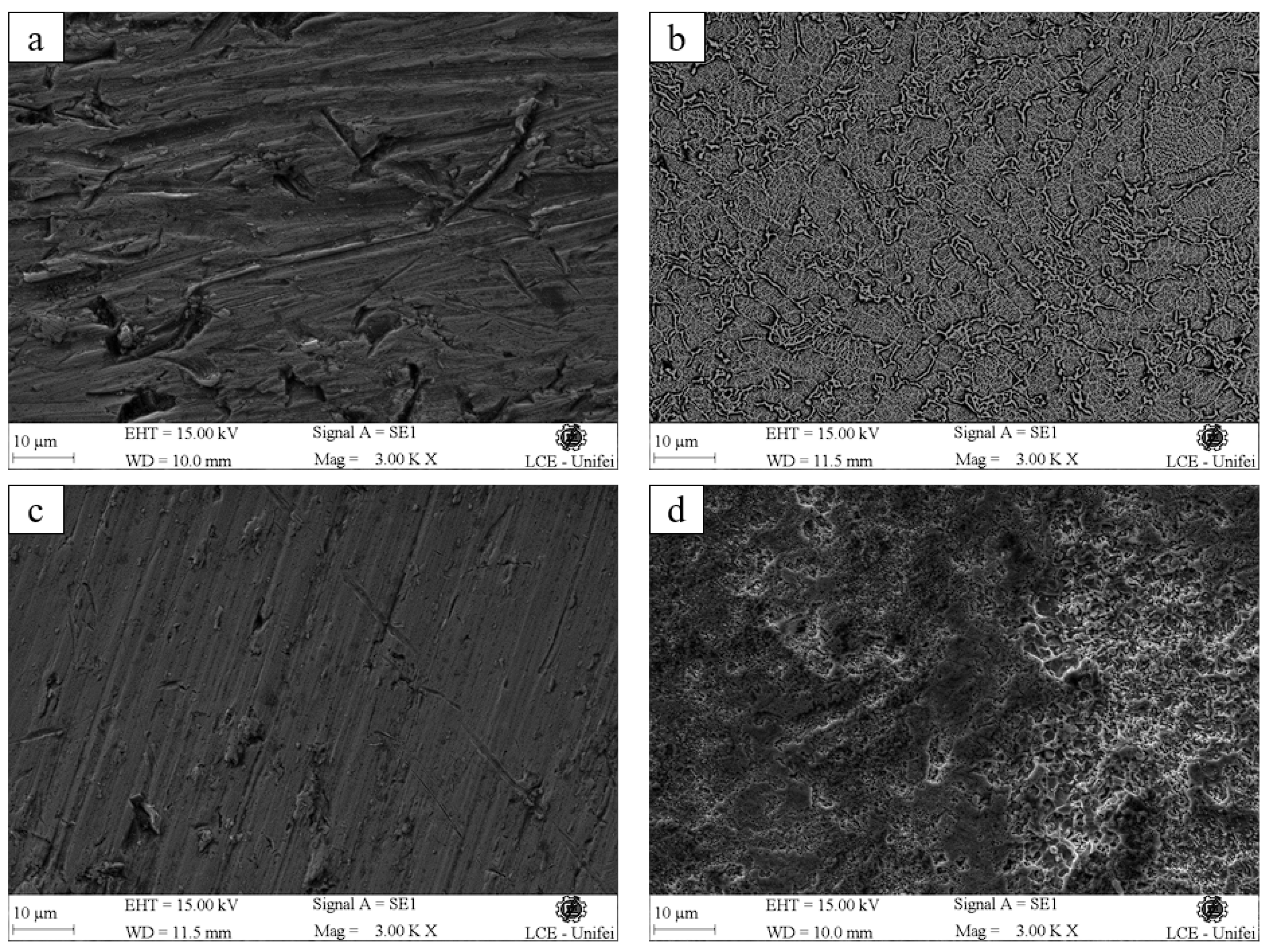
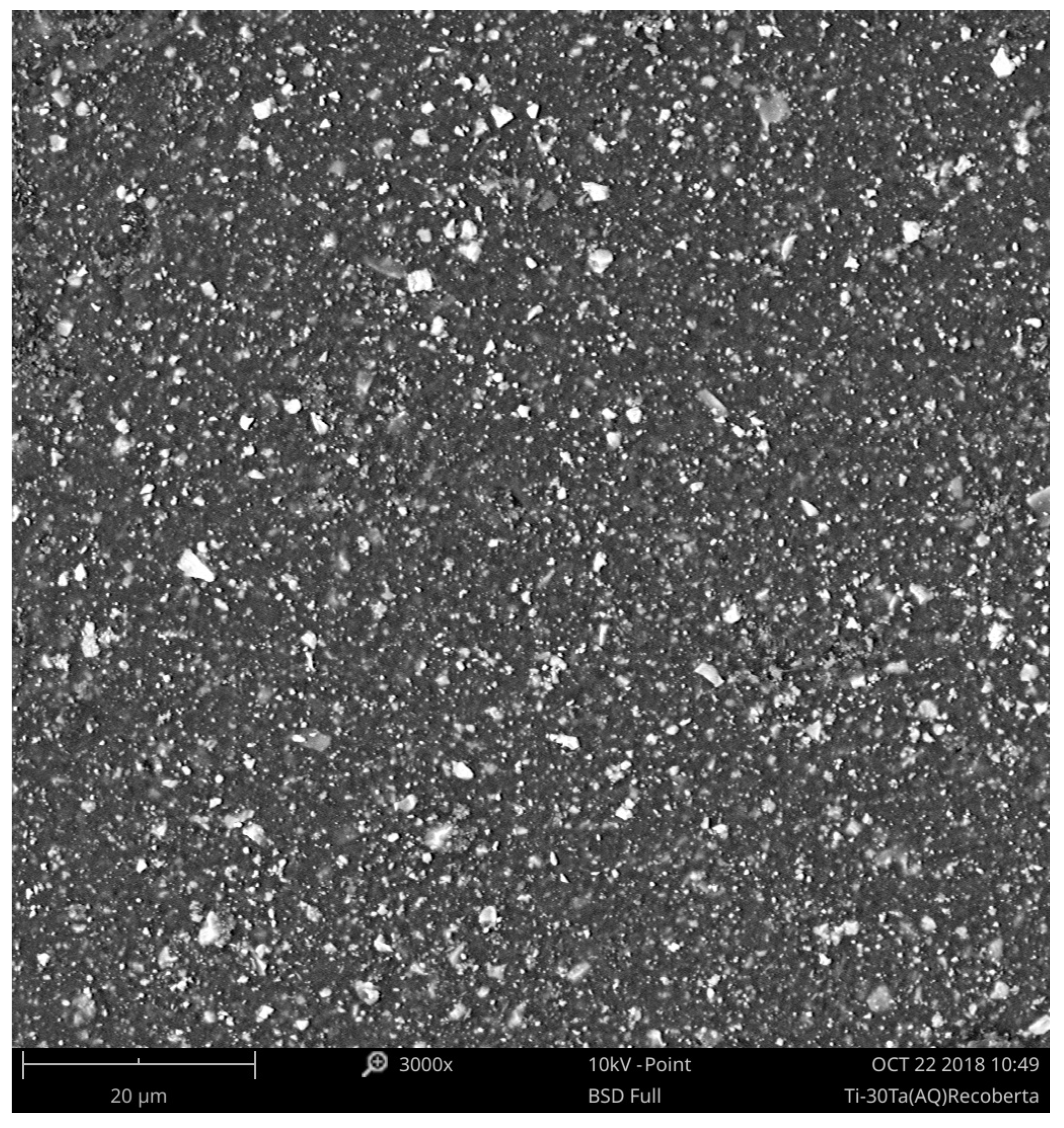
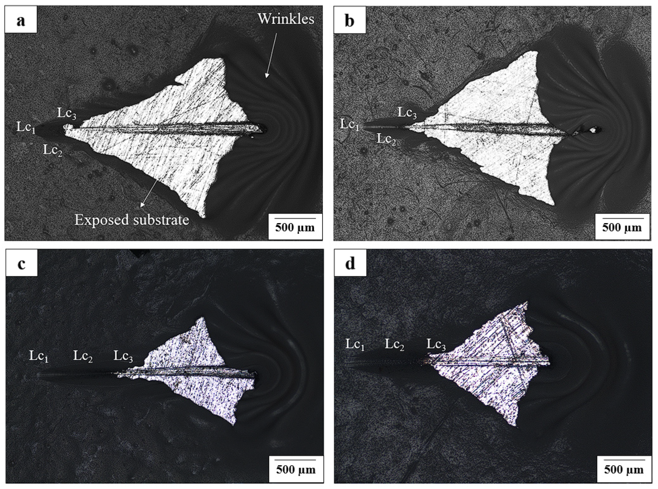
The topography of the treated samples before the coating process can be seen in
Figure 2. In
Figure 2a, the polished surface of the cp-Ti presents grooves throughout the surface. It is also possible to see the formation of valleys and peaks throughout the sample. The sample in
Figure 2b represents the micrograph of the cp-Ti sample with acid etching surface treatment, and grain boundaries can be seen (in light gray) separating regions with different crystallographic orientations (α and β phases of titanium), revealed due to the effect of the Kroll’s reagent. In addition, the presence of wrinkles was observed surrounding the whole surface. The arrangement of the elements that characterize a rough profile on the surface of the sample can be considered homogenous. However, there are some regions with a higher concentration of microcavities. This roughness pattern is responsible for characterizing the surface as isotropic, without preferential orientations of formed wrinkles.
Figure 2c refers to the micrograph of Ti-30Ta alloy with inherent surface irregularities from the polishing process, with thin cracks aligned parallel in the transversal direction, characterizing a preferential orientation. Finally, the Ti-30Ta sample is present in
Figure 2d, which represents the surface treated with acid etching. It is observed that there are grooves and micropores distributed throughout the sample. The difference in morphology of the cp-Ti and Ti-30Ta after the acid etching using Kroll’s reagent can be explained by the dioxide layer on the cp-Ti surface, which is one of the most difficult materials to corrode. Kroll’s reagent is the most efficient etchant employed on titanium alloys and can reveal the microstructure of these materials due to the presence of hydrofluoric acid and nitric acid, considered powerful oxidizing agents. Related to the Ti-30Ta surface, the reagent promoted a more eroded and corroded surface when compared to the cp-Ti due to the tantalum dissolving in hydrofluoric acid, where the passive layer of tantalum oxide is attacked strongly by this acid, leading to an increase in the surface oxidation.
The advantage of abrasive surface treatments is related to the fact that the deposited film penetrates the irregularities formed, increasing the adhesion strength at the interface of the coating material and the substrate [
48]. For this reason, surface treatments performed on the samples standardized the surface roughness to analyze the best surface treatment obtained in this work when associated with the adhesive strength of the P(VDF-TrFE)/BaTiO
3 coating film.
Obtained roughness data before the surface treatment are shown in
Table 4. The study of the rough surface of metallic substrates before the coating process can be found in the works of Biasetto and Elsayed [
51], Geng et al. [
52], Zhou et al. [
53], Guo et al. [
54], and Cordeiro et al. [
55], which possess
Ra (arithmetical mean of surface roughness) values very similar to the values described for cp-Ti substrates presented in this work (
Ra = 0.15 µm). Analyzing the results, there was no significant difference between the roughness for polish or acid etching treatment.
According to ASTM C1624-05 [
56], the roughness value for thin films formed by ceramic materials, with thickness ≤ 30 µm, must present
Ra < 0.5 µm. This range of values maintains the patterns defined by the ASTM standard, which guarantees the film adhesion on the substrate. As seen in
Table 4, the values found for the surface roughness of all samples (0.1–0.25 µm) are in accordance with the standard, since the value for the film thickness of this work was ≈20 µm for all substrates. Choi et al. [
48] have found in their studies that the relation between the surface roughness and the coating adhesion on a substrate refers to the increase in surface area. In other words, the surface roughness influences the interface between the substrate and the deposited film, improving the adhesion strength between both of them. Besides, the adhesion strength on rough surfaces may be adequate due to the high surface energy of atoms present on the scratched surface [
57].
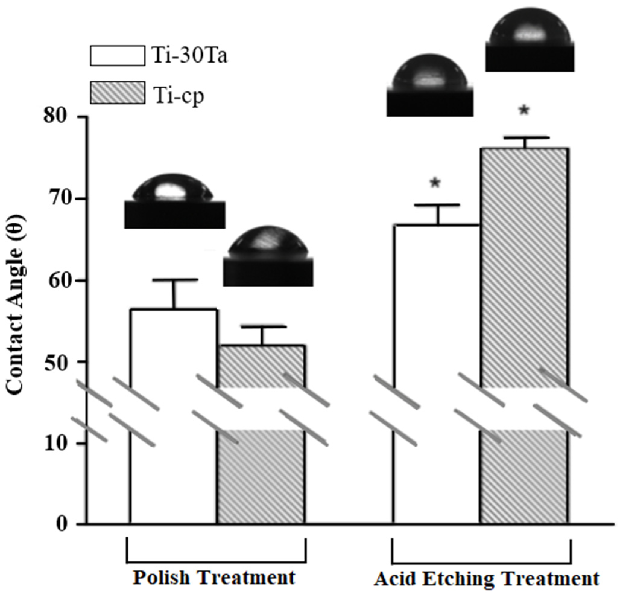
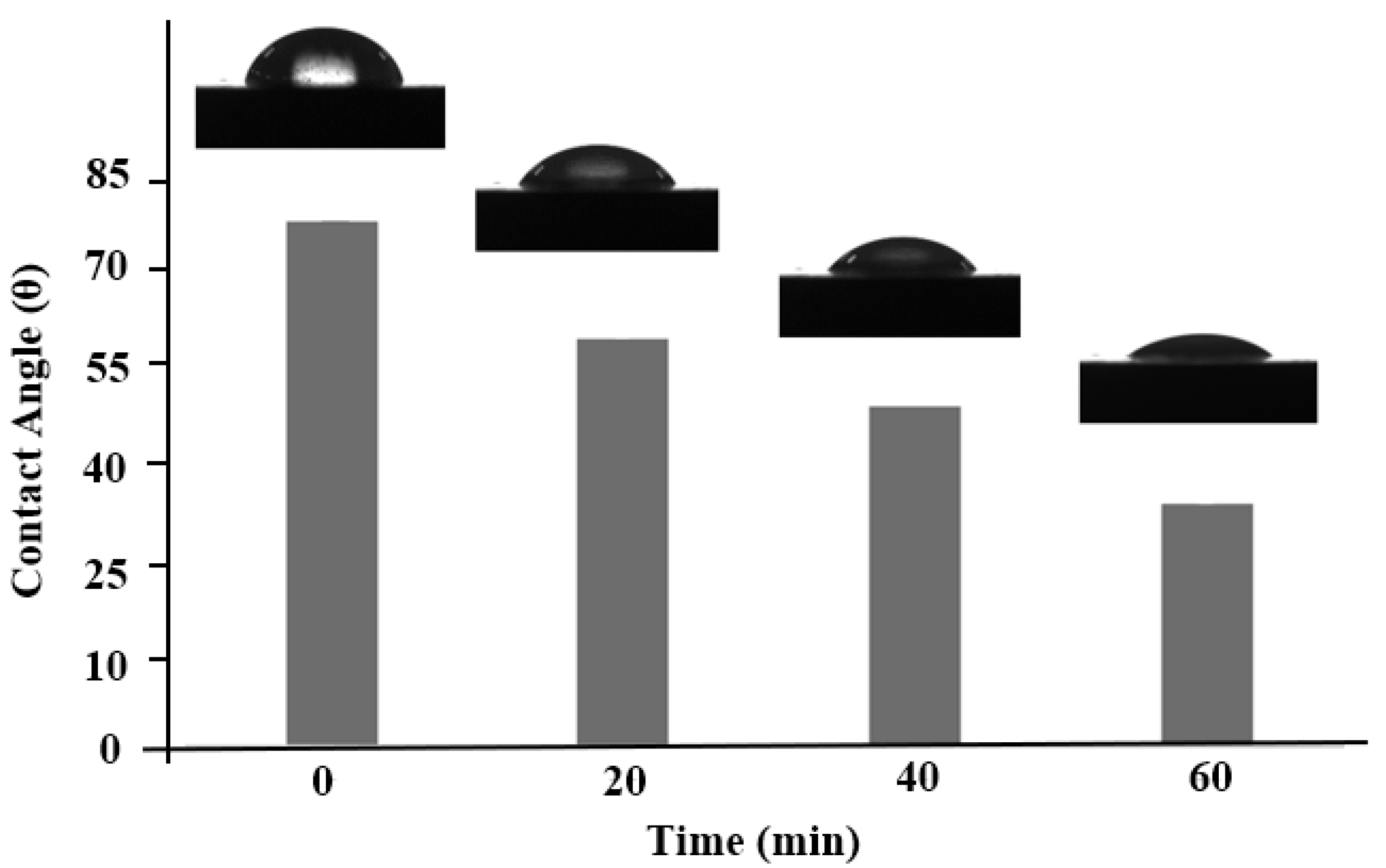
Figure 3 represents the contact angle measurements. According to the results, both substrates have absorptive characteristics, since the contact angle formed on the surface samples remains smaller than 90°, characterizing the surface of the samples as hydrophilic. The hydrophilicity or hydrophobicity is an intrinsic feature of wettability, which is a property associated with the surface energy of a material. Surfaces with high free energy are characterized by their hydrophilic nature, and the higher the surface energy of a material, the greater its ability to interact chemically with the liquid used [
58]. The wettability of a surface can determine the success of the adhesion of the thin film to various substrates on account of the interface tension of the film in the liquid state and the surface energy of the substrate in a solid state. The adhesion strength between the two surfaces is determined by the interactive nature of both materials, which are dependent on wettability. The tension between the film and substrate interface determines the fixation of the coating on a solid surface, which means that hydrophilic surfaces provide better adhesion [
19,
48].
Table 5 shows the surface energy of cp-Ti and Ti-30Ta samples calculated before the coating process. Analyzing the data, there was a statistically significant difference in the surface energy for the polish treatment group when compared to the acid etching treatment group (
p < 0.05). These results indicated that the surface energy suffers changes related to the preparation of the substrate’s surface. The surface energy of polished substrates presented values higher than substrates with acid etching treatment, suggesting that the polished surface is better than acid etching treatment.
The relation between the surface energy and adhesion strength is given through the attraction and repulsion forces, which have polar and dispersive components. When the polar components are higher than the dispersive ones, a greater adhesion strength occurs between the film and substrate. This implies that the surface energy is directionally connected to surface adhesiveness and surfaces with high free energy promote a better interaction with the deposited film [
18].
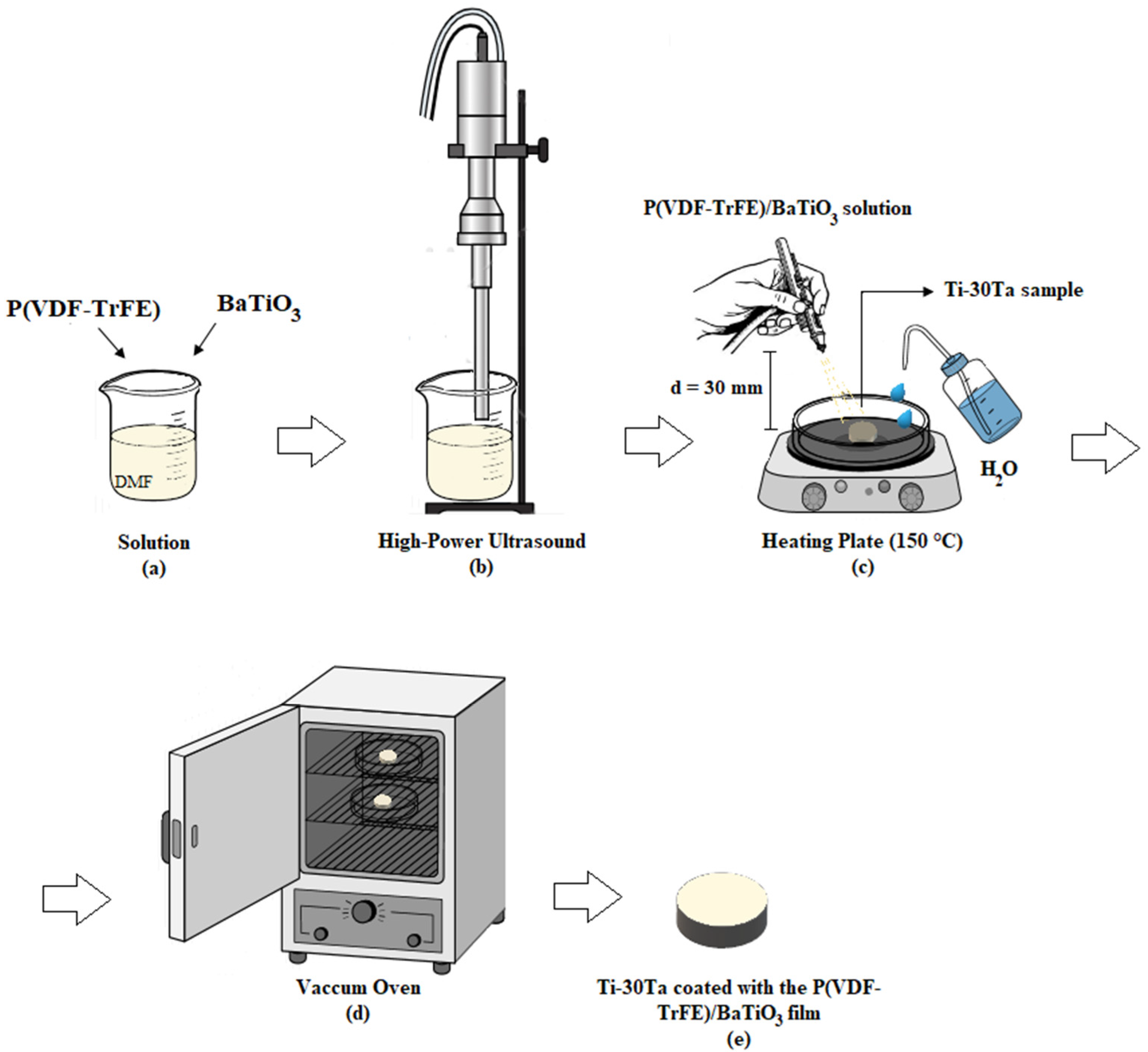
3.2. Evaluation of the P(VDF-TrFE)/BaTiO3 Film
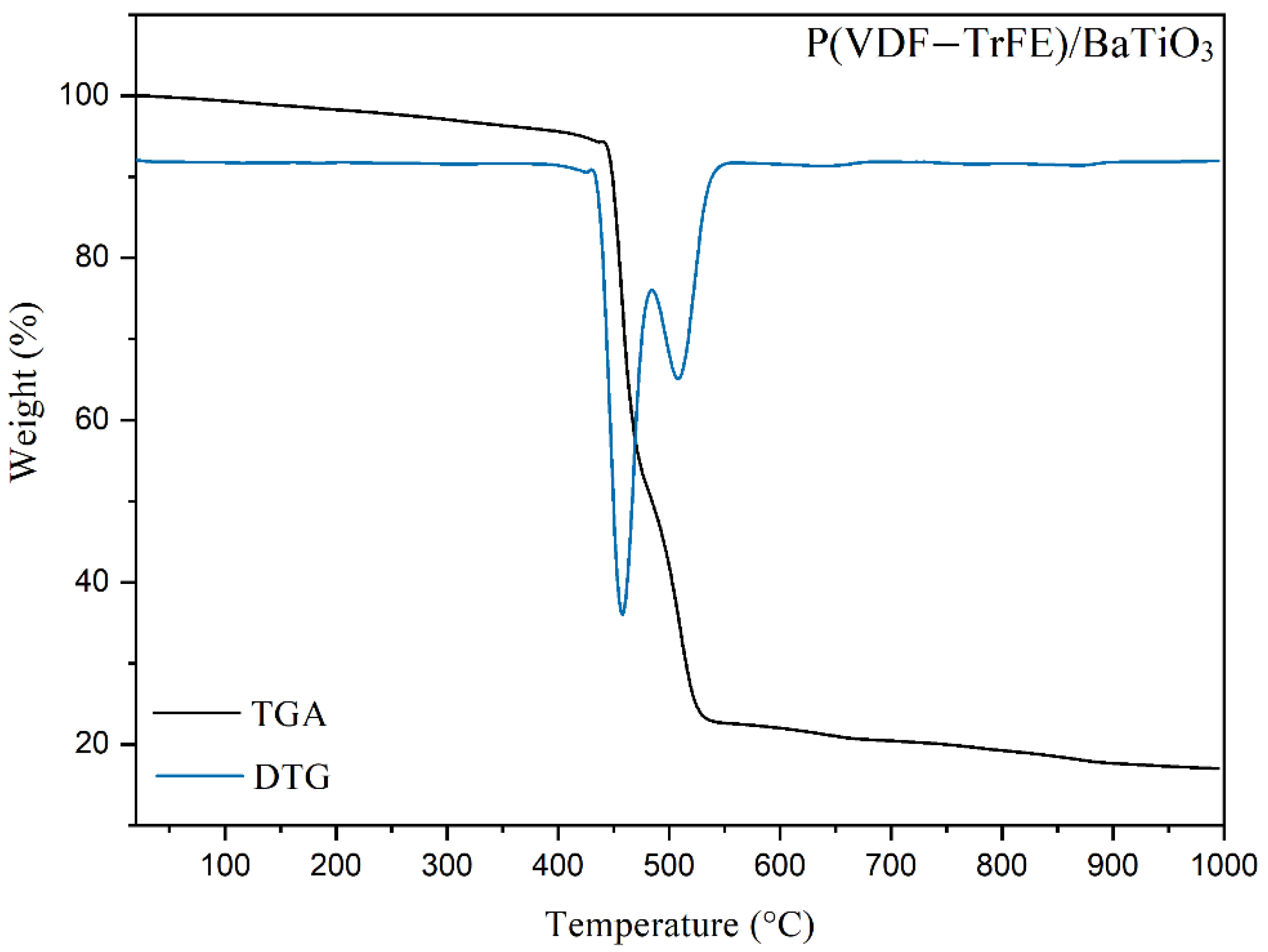
The thermal behavior of the P(VDF-TrFE)/BaTiO
3 films can be seen in
Figure 4. The TGA profile curve obtained in this work is very similar to the P(VDF-TrFE) curve, as seen in previous works [
59,
60]. In the range from 25 °C to 160 °C, the TGA curve showed no significant mass losses. This event indicates that the solvent used in the composite synthesis was dried entirely since there are no peaks on the DTG curve between 140–160 °C, which refers to DMF evaporation. At 450–550 °C there was a weight loss of the composite, where around 67.5% of its mass was decomposed. The remaining weight of the compound is considered residual mass, which can be attributed to the addition of BaTiO
3 and residues from the copolymer process, as seen in Simões et al. (2010) [
61]. Analyzing the derivative thermogravimetric curve (DTG) it is possible to identify events that are not seen by analyzing only the thermogram curve. The reaction reaches its maximum rate at 450 °C, and at 550 °C it is possible to observe a second lower intensity peak, indicating another weight loss process of the composite. The first DTG peak is assigned to the degradation of vinylidene fluoride, while the second peak is related to the degradation of trifluorethylene, since the mass loss (67.5%) at 450 °C is higher than the mass loss (≈33%) at 550 °C, reflecting the molar composition of the copolymer—VDF 80 mol% and TrFE 20% mol.
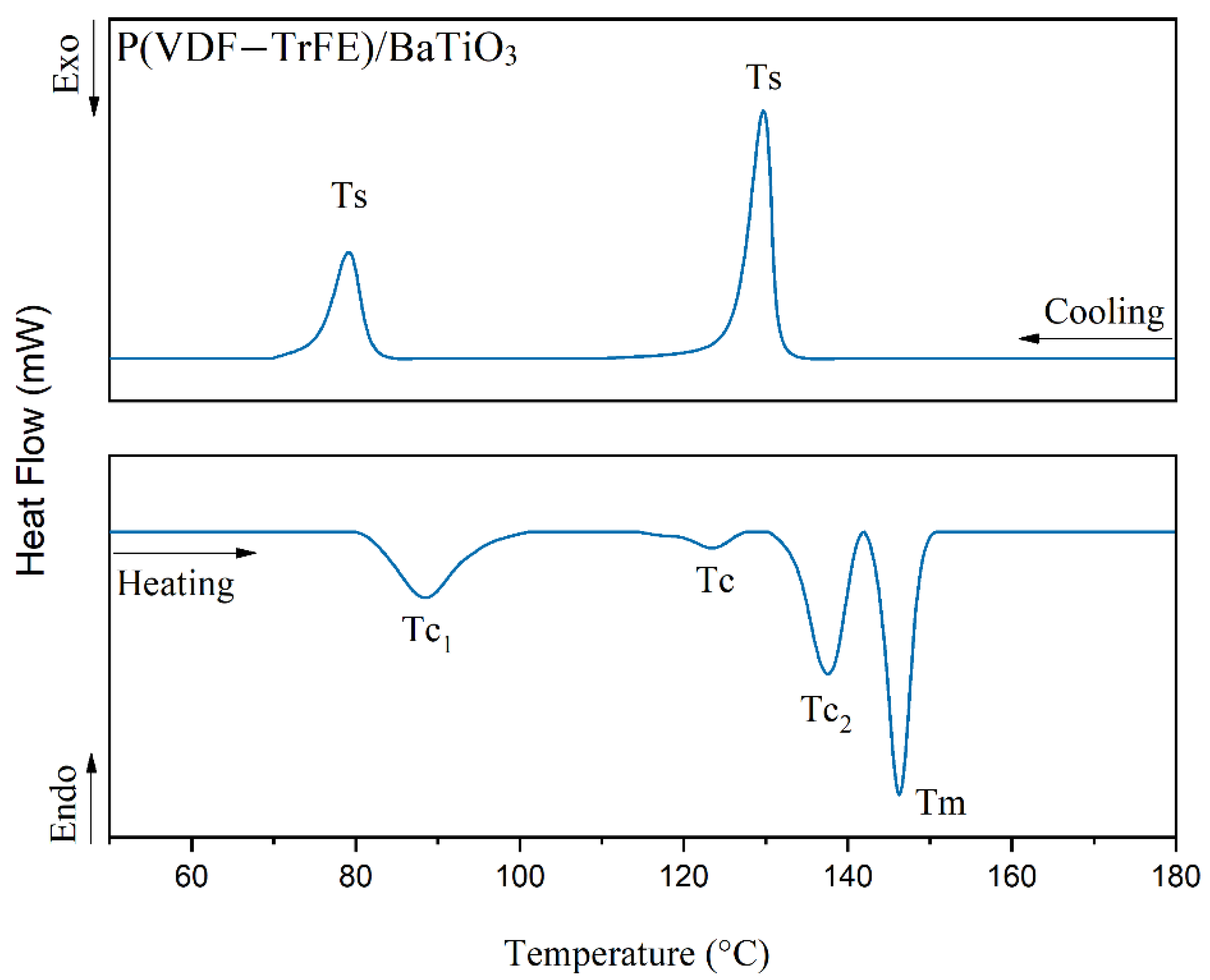
By DSC analysis, the nature of the energy involved in endothermic and exothermic processes that occurred during the controlled temperature rise could be assessed. During the drying of the composite onto the metallic Ti-30Ta substrate the temperature employed will exert an influence on PVDF-TrFE chain orientation; further, the annealing at temperatures above the Curie temperature (
Tc) induces crystalline formation, and it will generate a higher piezoelectric effect on the film. The correct temperature for drying and annealing the film can be better determined after an investigation of the transition temperatures obtained by DSC.
Figure 5 shows an endothermic peak at 88.46 °C, which corresponds to the Curie temperature (
Tc1) of the P(VDF-TrFE) copolymer. At 137.5 °C occurs a second phase transition (
Tc2), being similar to the copolymer catalog. Another two endothermic peaks occur at 125.6 °C, corresponding to the Curie transition of BaTiO
3, and at 146.23 °C, which corresponds to the melting transition (
Tm) of the copolymer. In the cooling stage, two exothermic peaks are observed at 132.4 °C and 78.9 °C. These peaks represent the crystallization temperature of the copolymer, represented by
Ts. The thermal behavior of the P(VDF-TrFE)/BaTiO
3 film can be compared to the literature, as seen in Genchi et al. (2016), Vacche et al. (2014) and Vacche et al. (2012) [
60,
62,
63], where similar transition temperatures were found as in this study.
The crystallinity of the composite was analyzed according to the data obtained by thermal events. In this way, it was possible to study the changes in the crystallinity after BaTiO
3 addition, as seen in
Table 6.
The crystallinity of the copolymer is in agreement with the literature, as observed in Nunes-Pereira et al. [
64]. Genchi et al. [
60] discussed the melting enthalpy of the material, which had an increase from 22 J∙g
−1 to 28 J∙g
−1, thus raising the crystallinity of the copolymer when BaTiO
3 particles were incorporated. However, Vacche et al. [
63], reported in their research that the addition of BaTiO
3 did not change the degree of crystallinity of the polymer after its recrystallization. These authors confirmed that at a certain volume of ceramic particles added to the polymer matrix, the crystallinity of the polymer also does not change significantly. In the present study, it can be observed that the addition of ceramic material particles into the polymer matrix increased the crystallinity of the copolymer by 15%, thus confirming the studies of Genchi et al. [
60]. The enthalpy of fusion increased approximately from 16 to 22%, meaning that the energy absorbed in the fusion of the compound is higher when related to the fusion energy of the copolymer.
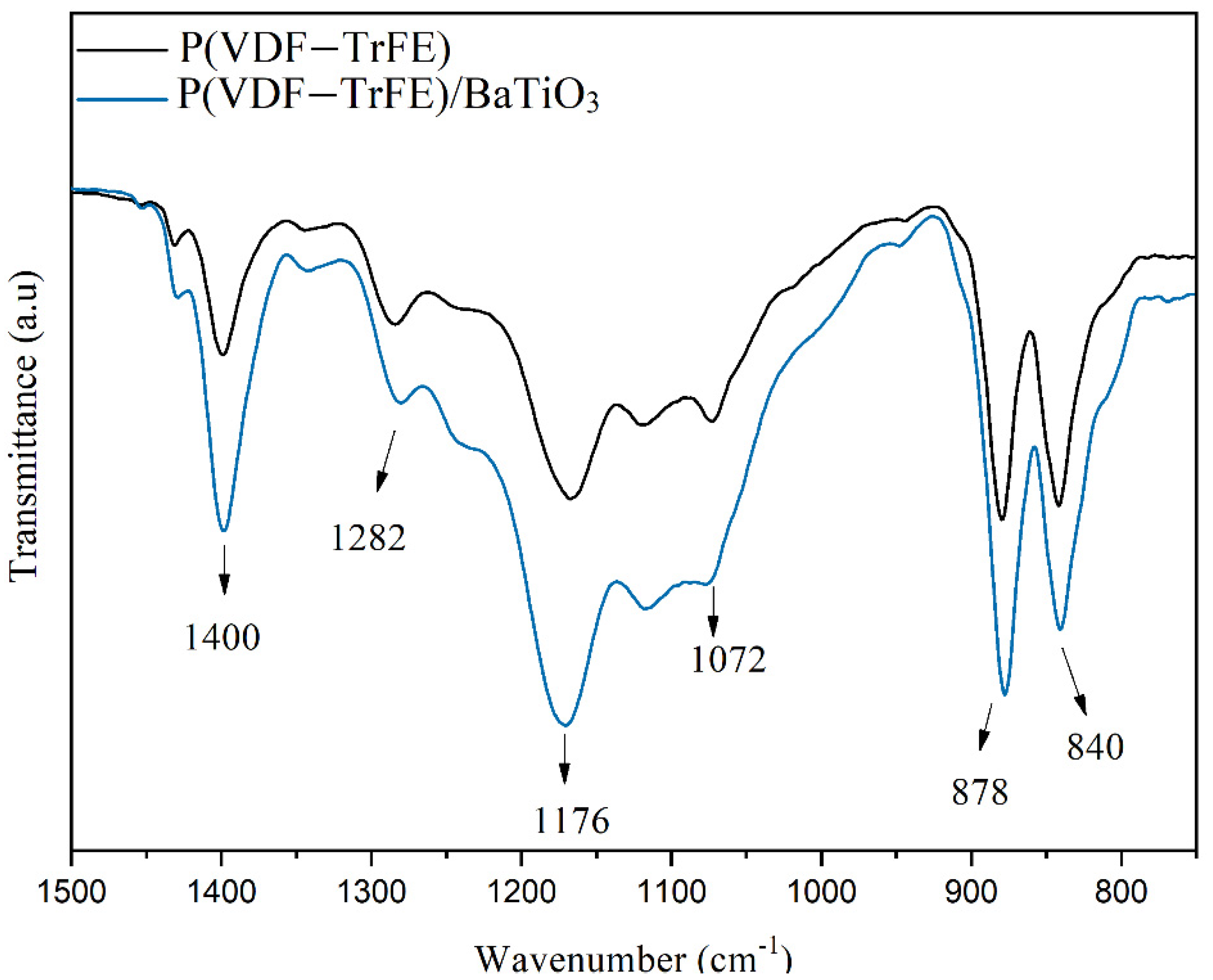
The spectra obtained through the FTIR technique were assigned to the crystalline phases of the P(VDF-TrFE)/BaTiO
3 film. The composite, being a copolymer and ceramic, has a characteristic vibration mode for each phase, which is discriminated through the absorption bands of atomic vibrations. For this reason, the study of the phases of the composite before and after the addition of BaTiO
3 is relevant.
Figure 6 shows the FTIR spectra of P(VDF-TrFE) in powder form compared with the FTIR spectra of P(VDF-TrFE)/BaTiO
3. Intense absorption bands are exhibited at 840 cm
−1, 1282 cm
−1, and 1400 cm
−1, characteristic of the ferroelectric β phase of P(VDF-TrFE). The peaks from 1072 cm
−1–1176 cm
−1 are common to the α, β, and γ phases. The peaks at 840 and 878 cm
−1 are associated with a –C–F symmetric stretch and –CF
2 bond in-plane rocking deformation, respectively. The peak at 1282 cm
−1 represents the –CF
2 asymmetric stretch, C–C bond symmetric stretch and CCC scissoring vibration. Finally, the peak at 1400 cm
−1 is associated with the –CH
2 wagging frequency and –C–C– asymmetric stretch [
27,
65,
66,
67]. These peaks suffered an intense increase after the incorporation of BaTiO
3 in the polymeric matrix, which reflects in the piezoelectricity of the material, as seen in Qi et al. (2013) [
66]. According to these authors, the increase in the crystallinity of the copolymer after BaTiO
3 addition can be explained by the chemical bonding between them. The BaTiO
3 content increases due to the oxygen vacancies in the composite matrix, which have positive charges. The fluorine atoms of the polymer, which have negative charges, fill the oxygen vacancies. Consequently, the interface and the space charges are decreased, allowing the electric dipoles to move and rotate easily, increasing the dielectric constant of the composite.
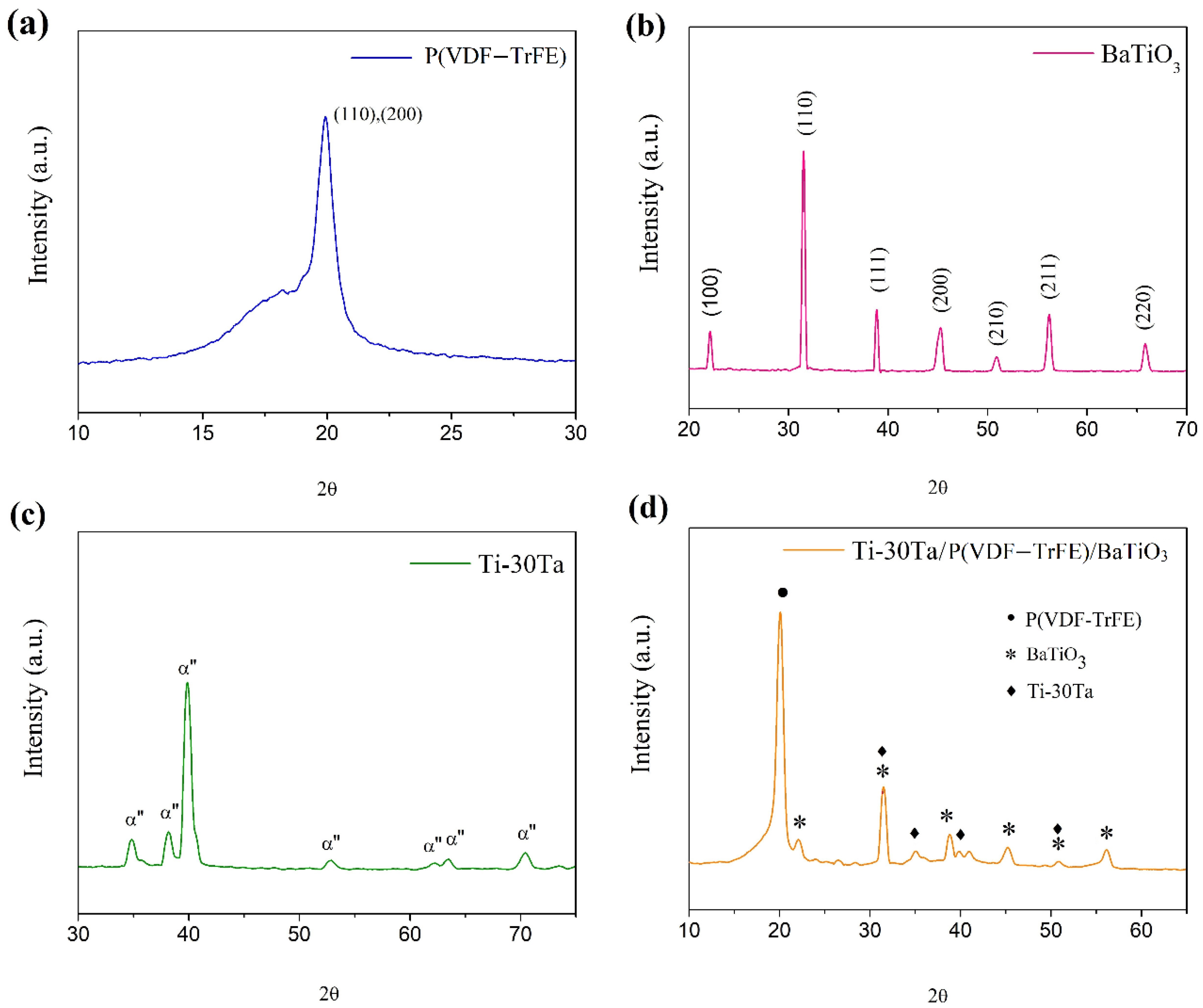
Analyzing the diffractogram in
Figure 7a is possible to verify that P(VDF-TrFE) presents crystalline behavior. The P(VDF-TrFE) spectra show a broad peak at 19.9°, which corresponds to the reflection of crystalline planes (110) and (200) of the orthorhombic phase of the copolymer. This phase has a similar crystalline structure to the β-ferroelectric phase of PVDF, also confirmed by the FTIR analysis [
68]. Furthermore, a small peak is observed at 17.1° corresponding to the α phase of P(VDF-TrFE). The copolymer semi-crystalline phase is noted at 18.7°, which is represented by the inflection point in the diffractogram, as observed in Genchi et al. [
60].
Figure 7b shows the BaTiO
3 diffractogram. The lattice parameter data obtained show that the unit cell of BaTiO
3 is tetragonal of the crystalline system P4 mm, as observed in the crystallographic sheet PDF-2 05-0626. Complementing the analysis, these results confirm that there are no BaCO
3 impurities in the ceramic powder [
68,
69]. Ti-30Ta spectrum can be seen in
Figure 7c, which corresponds to the crystallographic sheet PDF-2 01-089-5009. The spectrum confirms the presence of the characteristic peaks of the hexagonal metastable phase α”. These results can be confirmed in previous studies [
70,
71,
72]. Finally, the spectrum of the composite formed from the Ti-30Ta alloy coated with P(VDF-TrFE)/BaTiO
3 film can be seen in
Figure 7d. Analyzing the diffractogram, seen are associated peaks with the phases of all materials. The diffracted peak in the angular region that corresponds to 20° represents the P(VDF-TrFE) copolymer peak. Peaks viewed at 30–35° correspond to the BaTiO
3 tetragonal phase. The α” phase of the alloy is represented by peaks found at 40°. These peaks suffered a considerable decrease in their relative intensity when compared to the Ti-30Ta alloy diffractogram. This decrease may be related to the P(VDF-TrFE)/BaTiO
3 coating, which interfered in the diffraction of the corresponding plane. Moreover, there were no significant phase changes attributed to the coating process.


 ,
, 


