Article

Design of Cotton Recovery Device and Operation Parameters Optimization

1
College of Mechanical and Electrical Engineering, Shihezi University, Shihezi 832000, China
2
Mechanical Equipment Research Institute, Xinjiang Academy of Land Reclamation Sciences, Shihezi 832000, China
3
Institute of Agricultural Mechanization, Xinjiang Academy of Agricultural Sciences, Urumqi 830091, China
*
Author to whom correspondence should be addressed.
Agriculture 2022, 12(9), 1296; https://doi.org/10.3390/agriculture12091296
Submission received: 31 July 2022 / Revised: 19 August 2022 / Accepted: 20 August 2022 / Published: 24 August 2022
(This article belongs to the Special Issue Design and Application of Agricultural Equipment in Tillage System)

Abstract

:
This research aims to optimize the working parameters of the sawtooth-type recovery device for cotton fallen on the ground to enhance cotton’s recovery effect. Firstly, the cotton-picking mechanism and cotton unloading mechanism of the cotton recovery device were designed. The movement trajectory of the serrated tooth end of the designed device, the cotton non-missing picking condition, and the cotton unloading condition were noted. Secondly, virtual simulation technology developed a model of the interaction process between the picking equipment and the soil. To determine the optimal combination of operating parameters for the recovery device, a three-factor, three-level response surface optimization test was conducted using Box–Behnken’s central combination method with operating machine speed, spacing between serrated discs, and serrated disc speed as the test factors, and the picking and impurity rate as the test indexes. In addition, a response surface regression model was developed to analyze the effects of the selected factors on the recovery unit, and each factor was optimized. When the picking and impurity rates were 79.09% and 35.12%, respectively, the optimal operating speed of the machine was 0.96 m/s, the spacing of the serrated discs was 40 mm, and the speed of the serrated discs was 68 rpm. The relative error between the experimental findings and the theoretical optimized values was less than 5%, and the optimized working parameters were reliable. This study can provide a reference for the device used to recover cotton that has fallen to the ground.

1. Introduction

Cotton is a globally significant crop that can be used as the textile industry’s raw material. In developing countries, cotton production is essential for economic growth and improving living conditions [1,2,3]. There are cotton-growing regions throughout Asia, Africa, the United States, Europe, and Oceania, but they are located primarily in Asia and the Americas [4]. China is the world’s largest consumer and the second-largest cotton producer, and cotton production is vital to its national economy [5,6,7]. China’s leading cotton-producing region is in Xinjiang. In recent years, the rate of cotton harvesting by machine has steadily increased, and mechanical cotton harvesting has grown popular [8,9,10,11]. The quality guideline for cotton picker operations mandates a loss rate of less than 5 percent for mechanical harvesting [12]. In practice, however, cotton falls to the ground due to the effects of defoliation and ripening, cotton-picking machine head contact, weather, and numerous other causes. According to early studies, approximately 3 percent of cotton falls unharvested yearly. According to statistics [13], in 2021, the cultivated cotton area in Xinjiang was around 2.51 × 10⁶ hm2, and the yield reached 5 × 10⁶ tons. Approximately 1.5 × 10⁵ tons of cotton are left in the cotton field after a 3% loss, and the amount of cotton that has fallen is ample. Consequently, one of the challenges of cotton resource exploitation is the effective recovery of cotton distributed over the ground.
Currently, the existing ground recovery technologies for collecting cotton fallen on the ground are primarily pneumatic, mechanical, and mechanical combinations in the research and development stage [14]. Lawrence A. Lehman et al. [15] invented a gripper-type fallen cotton pickup device equipped with a flexible belt with transverse grooves that open and close when the belt runs through the circular surface of the front roller, thereby grasping the fallen cotton in the furrow while wedging in a significant amount of soil and broken branches. The CXC-1.2-type horizontal spindle picker manufactured in the former Soviet Union was fitted with an airflow picker at the rear of the machine. This airflow picker collected cotton that touched the ground through the suction pipe installed on the fan. However, cotton leaves are easier to inhale, increasing the number of impurities in cotton. Jianlong et al. [16,17] invented an air-suction-type picking machine for cotton fallen on the ground based on the principle of negative pressure suction picking; here, the front-end comb teeth scrape the cotton off the stalks as the machine advances, while the blowing ports on both sides of the cotton collection platform blow the cotton fallen on the ground to the center of the platform and then suction the cotton into the collection box using the suction tube. The machine’s structure is simple, but the impurities, such as cotton sticks and leaves, are scraped to the ground’s surface, making subsequent cleaning more difficult. Li-Guang et al. [18] invented a pickup roller with retractable pickup teeth for cotton that has fallen to the ground. When the pickup teeth move to the surface, they extend and hook cotton, and when they hook and cling onto the back of the pickup roller, they retract, releasing the cotton. Its simplistic structure will pick up mulch and drip irrigation tape and wrap it around the drum, causing machine failure.
Regarding existing technologies, a pneumatic cotton recovery method inhales a significant amount of crop waste, cotton stalks, soil, and other impurities during operation. As a result, cotton includes a high rate of impurities and thus reduces the unit’s capacity to run continuously. In addition, the uneven surface of the field makes it impossible to recover the majority of cotton that has fallen to the ground using a mechanical approach.
Aiming at the characteristics of the cotton machine harvesting in Xinjiang (e.g., the enormous volume of cotton fallen on the ground and lack of appropriate recovery equipment) and based on the structure and characteristics of an existing cotton recovery device, a sawtooth-type recovery device was designed. Through theoretical analysis and field testing to determine the machine’s reasonable structure and operating parameters, the influence of different factors on the effect of cotton recovery was explored, and a better combination of parameters was obtained. This study provides a theoretical and technological reference for developing cotton recovery equipment.

2. Materials and Methods

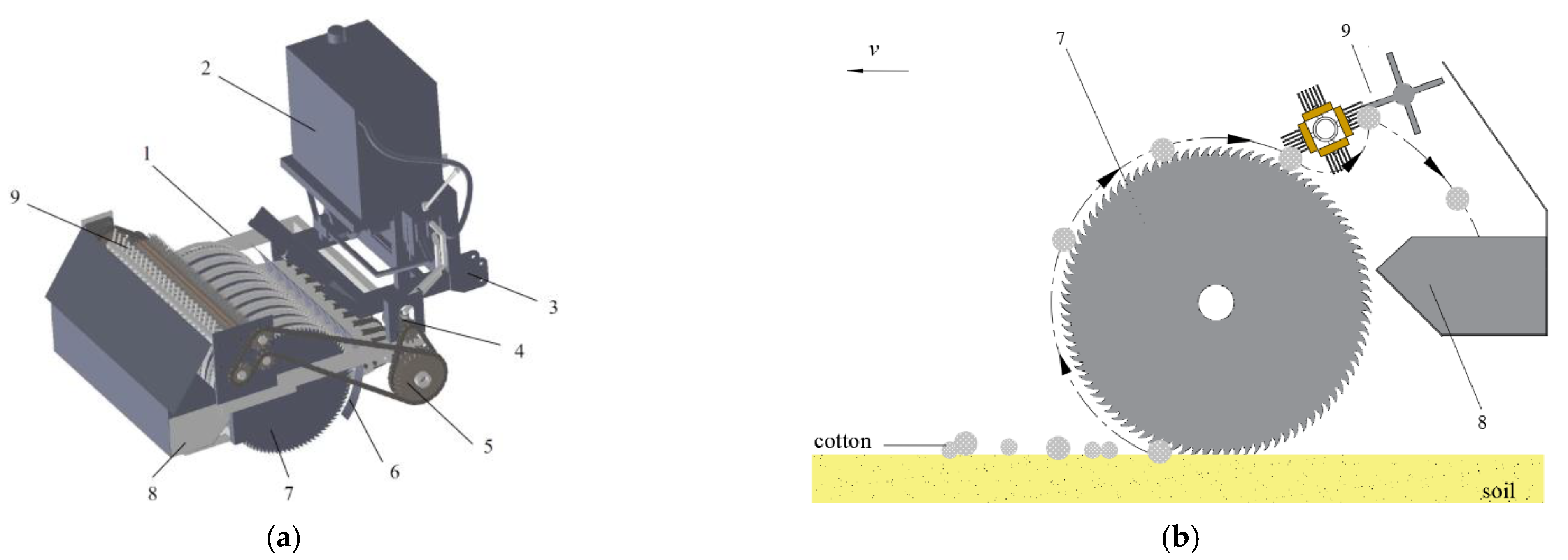
2.1. Structure and Operating Principle of the Cotton Recovery Device

Figure 1 shows the structure of the sawtooth-type recovery device for fallen cotton, which consists mainly of the frame, straw guard, power transmission system, sawtooth roll-tie cotton-picking mechanism, cotton unloading mechanism, cotton collection box, and other components. The tractor places the device on the ground via the suspension, and the ground wheel for each group of cotton-picking parts advances under traction after touching the ground. The forward process achieves topographical adaptation according to the difference in the ground surface undulation. The transmission system includes a hydraulic motor, sprocket, and other components. The device is powered by the tractor’s rear output shaft, and the hydraulic motor drives the sawtooth roll-tie-type cotton-picking mechanism and the unloading mechanism. The main technical parameters of the device are shown in Table 1.
When the device is in operation, the serrated disk rapidly rotates clockwise; the end of the teeth of the serrated disk first contacts the cotton fallen on the ground and gradually deepens as the machine advances; the serrated teeth completely hook the cotton fiber and turn backward; and the cotton boll shell, cotton peach, and large cotton rod are thrown out under the action of the centrifugal force. Since the friction coefficient of the cotton differs between the brush roller and the serrated disc, the cotton on the serrated disc can be brushed off when the hooked cotton continues to rotate backward and comes into contact with the brush roller rotating at reverse high speed [19,20]. In addition, the wind force generated by the brush roller at high-speed rotation blocks part of the impurities from entering the collection box. Subsequently, the stripping roller rolls the cotton wound on the brush roller to the collection box at the frame’s rear to complete the picking up of cotton fallen on the ground.

2.2. Design and Analysis of the Major Components

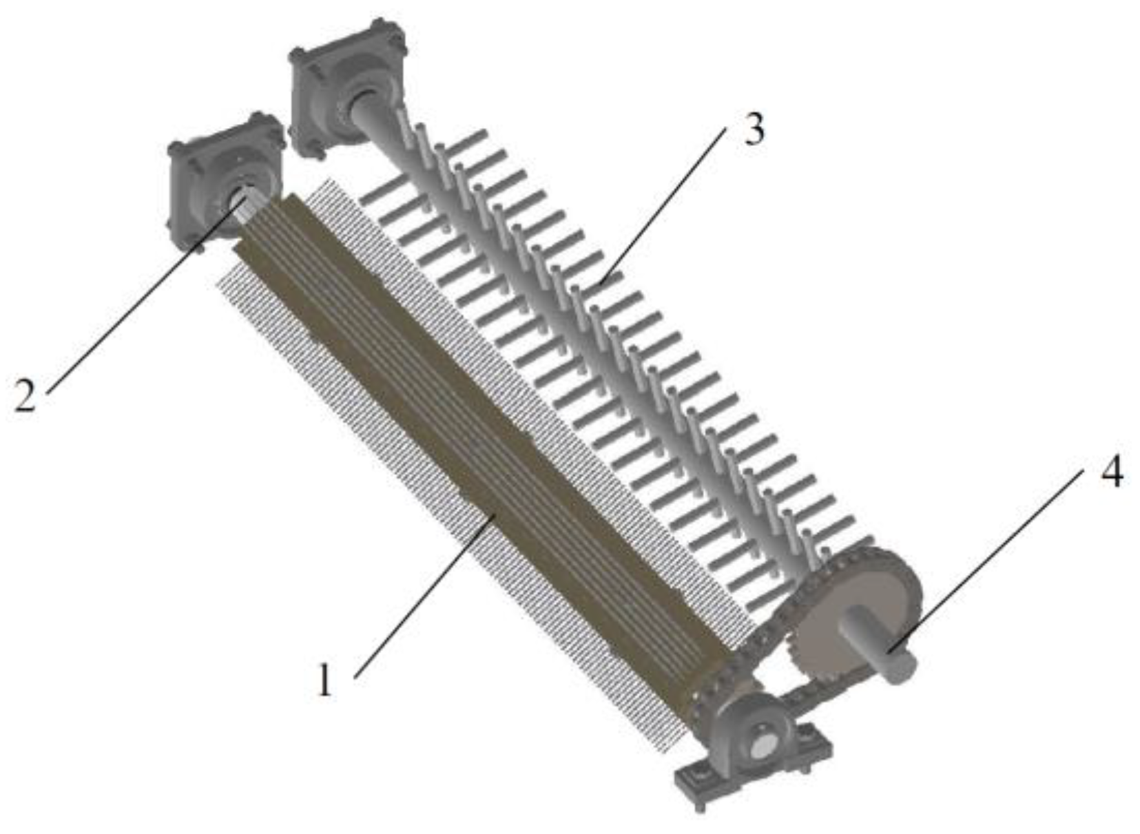
2.2.1. Design of the Sawtooth Roll-Tie-Type Cotton-Picking Mechanism

The principal mechanism of the device is a sawtooth roll-tie-style cotton-picking mechanism. The cotton-picking mechanism comprises ten groups of picking components, including a guard ring, ground wheel, serrated disc, and straw shield (Figure 2). Its primary purpose is picking up, hooking, and transporting dropped cotton to the unloading location. The operational width of the cotton-picking section is 1000 mm, the diameter of the ground wheel is 610 mm, and the sawtooth disc circumference has 90 saw teeth evenly spaced. In addition, the serrated disc’s top circle and tooth root circle diameters are 600 and 560 mm, respectively.

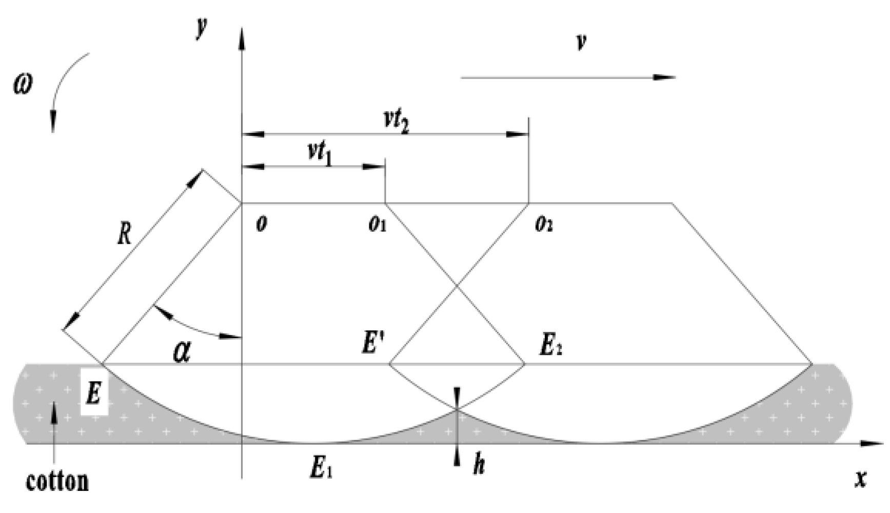
2.2.2. Analysis of the Motion Characteristics of the Serrated Disc

When the device is operating, the circumferential line speed below the serrated disc is the same as the forward direction. The trajectory of the saw tooth end E point is depicted in Figure 3, with the machine moving forward at a constant velocity v, the forward direction for the x-axis being positive and the y-axis being vertically upward, and the saw tooth disk rotating at a constant angular velocity ω.
The serrated disc moves from point F1 to point F after time t, while the sawtooth tooth endpoint E1 rotates to point E. If the angle through which the sawtooth tooth end rotates α(α = ωt), then the sawtooth tooth end E point’s equation of motion is:
{ x = R sin ω t + v 0 t y = R R cos ω t
The first-order derivative of the above system of equations with respect to time t yields the sawtooth end velocity.
{ v x = d x d t = ω R cos ( ω t ) + v v y = d y d t = ω R sin ( ω t )
where R is the radius of rotation of the serrated disc, mm; F and F1 are the center of rotation of the serrated disk at different moments.
According to Equation (2), it can be shown that the backward horizontal component speed of the machine is determined by the magnitude of vx, and the backward horizontal component speed ensures the effect of the saw teeth hooking the cotton. When ωRcos(ωt) + v = 0, we can obtain:
ω R v = 1 sin ( ω t )
v 1 = ω R
Let the ratio of the serrated disc’s circumferential linear velocity v1 to the device’s forward velocity v be:
λ = v 1 v
According to Equation (2), when λ < 1, the serrated tooth end backward velocity is 0, which cannot complete the picking operation; when λ > 1, the serrated disk rotation at the same time relative to the ground in the picking area has backward velocity; in this movement, the landed cotton is hooked up with the serrated upward movement. Therefore, the value of λ can pick up the landing cotton, and thus has an important impact; if the value is too small, it is easy to miss the phenomenon; if the value is too large, the impact of the serrated teeth on the landing cotton increases, resulting in the fracture of cotton fibers, which only hook up a small part, plus the difficulty of picking up. According to the results of the preliminary field test, when the machine operating speed is set at v = 0.6~1.2 m/s, λ = 2.1~2.8, the device operating performance is good and can complete the cotton-picking operation. Bringing v and λ into Equation (3), the sawtooth disc speed can be initially determined as n = 40.11~106.95 rpm.

2.2.3. Analysis of the Conditions of Flooring Cotton without Missing Pickup

To achieve continuity when picking cotton, there should be no gap between the motion trajectories formed by the tooth ends of adjacent serrations; that is, adjacent serrations are required to just tie into the initial point E when the tooth end of the previous serration has not left the end point of picking cotton E2. The serrations arrive at the initial point E of tying into the cotton; at this time, the initial phase angle between LOE and Y-axis is θ. The time elapsed from the movement of the serrated disk axis O to O1 is t1, and the time elapsed from the movement to O2 is t2. According to the analysis presented in Figure 4,
h R ( 1 cos α )
where h is the distance between the intersection of two adjacent serrations in the trajectory of the landing cotton from the deepest point of the serration into the cotton (mm).
When E2 and E1 coincide, the criterion for continual collection of cotton fallen to the ground is satisfied, and the critical condition can be attained as:
L o 1 o 2 = 2 R sin α
where L O 1 O 2 is the previous saw teeth leaving the end of the pick cotton point immediately after the next saw teeth just into the initial point of tying cotton serrated disc axis horizontal movement distance (mm).
Figure 4 illustrates the parameters that must be met to achieve continuity while picking up cotton:
2 R sin α v ( t 2 t 1 )
One must enter the cotton from the tip of the serration to pick up the cotton; the angle of the sawtooth end is rotated for 2α, and the time required is t1 = 2α/ω. When the number of saw teeth on the serrated disc is set to z, the adjacent serrated angle can be obtained as θ = 2π/z. Subsequently, the next saw teeth turn the angle after the serrated tooth end is located at point E; the required time is t3 = 2π/, where t3 = t2t1. Thus, t1, t2 appear in Equation (8), and finishing can be obtained as:
ω π v z R sin α
In Equations (6)–(9), t1 is the time required for the serrated tooth end to move from E to E2 (s); t2 is the required time for adjacent serrated tooth ends to hook the cotton individually (s); t3 is the time required for the latter serrated tooth end to move to point E until the previous serrated tooth leaves point E2 (s); and α is the initial phase angle of the serrated tooth end from immediately hooking the cotton (°).
Using the sine theorem, we can write:
R sin 90 ° = R H cos α
According to the structure and dimensional data of the sawtooth-type picking device, R = 300 mm was selected as the radius of the rotation of the serrated disk. The maximum depth of the serrated teeth H was set to 20 mm, and the initial phase angle α = 21.04° was calculated using Equation (10). Under the condition of continuously picking up cotton, the number of saw teeth on the same serrated disk was z = 90; machine forward speed v was set in the range of 2–5 km/h (0.56–1.39 m/s) according to the field situation; ω was calculated as 0.198 rad/s. In other words, the serrated disc speed of 1.89 rpm is sufficient to meet the demands of continuous cotton plucking.

2.3. Design of the Cotton Unloading Mechanism

To take off cotton that is picked up by the serrated disc and send it to the collection box, a cotton unloading mechanism was designed for the structural characteristics of the sawtooth roll-tie cotton-picking mechanism; its structural schematic is depicted in Figure 5. The unloading mechanism consists of brush and stripping rollers. The brush roller comprises a drive shaft and a brush strip, with the brush strip having dimensions of 930 mm in length and 60 mm in width. At 40 mm in length, the bristle is composed of a nylon substance with good wear resistance and tensile strength. Four brush strips are installed at equal intervals around the perimeter of the drive shaft, and each brush strip is bolted to the drive shaft. A cotton removal shaft and spikes are fitted on the cotton removal shaft of the cotton removal roller. Here, the cotton removal shaft has a 20 mm diameter. In addition, the spikes are circumferentially placed on the drive shaft, and there are four rows with 22 or 23 spikes in each row, with a 30 mm distance between spikes.
A hydraulic motor drives the cotton unloading and cotton-picking mechanisms to rotate in opposing directions via chain drive and reversing gear during operation. When the tooth end of the serrated tooth hooks the cotton to the position of contact with the brush roller, the force of the brush roller is sufficient to overcome the resistance of the serrated tooth and brush the cotton off the serrated tooth; this is because the friction coefficient between the brush and the cotton fiber is more significant than that between the cotton fiber and the serrated tooth [21].
Figure 6 depicts the force sketch of cotton while unloading cotton. The equilibrium force condition of cotton is as follows:
{ F f + G cos θ = F ω 1 F + G sin θ = F N G = m g F ω 1 = 4 π 2 n 1 2 m R
where m is the mass of cotton fallen on the ground on a single serrated type (g); g is the acceleration of gravity (9.8 m/s2); n1 is the rotational speed of the serrated disk (rpm); R is the instantaneous rotation radius of the serrated disk (mm).
The force of the brush roller on the cotton and the combined centrifugal force on the cotton on the serrated disk must be larger than the force of the serrated teeth on the cotton for the brush rollers to brush down the cotton from the cotton-picking mechanism smoothly. According to Equation (11), the condition necessary for the cotton to detach from the serration is:
n 1 = 1 2 π F f + m g cos θ m R
Using the universal testing equipment, the force Ff of the saw teeth on the cotton was measured to be approximately 2.2 times the cotton’s specific gravity, or Ff = 2.2 mg. In addition, R = 300 mm was chosen as the rotational radius of the serrated disk. When cosθ = 0, the minimum rotation speed of the cotton out of the serrated disc was n1 = 80.96 rpm. If the speed is poor, the picking efficiency will be low, and the operating requirements will not be reached. Under centrifugal force, cotton is easily dislodged from the sawtooth disk if the speed is extremely high. Combining theoretical analysis with the actual operation, the initial serrated disk speed was set as 60 rpm. According to [22], the brush roll surface’s linear speed is typically 1.5–2 times that of the serrated tooth end. The spinning radius of the brush roller is 85 mm, and its computed speed range is 317.64~423.53 rpm. In conjunction with the preliminary test, the final brush roller speed determination is 400 rpm. Since the speed of the serrated disc cannot exceed 80.96 rpm, the speed ratio of the serrated disc to the brush roll exceeds 1:5, and the brush roll will brush over the serrated teeth many times without missing the cotton.

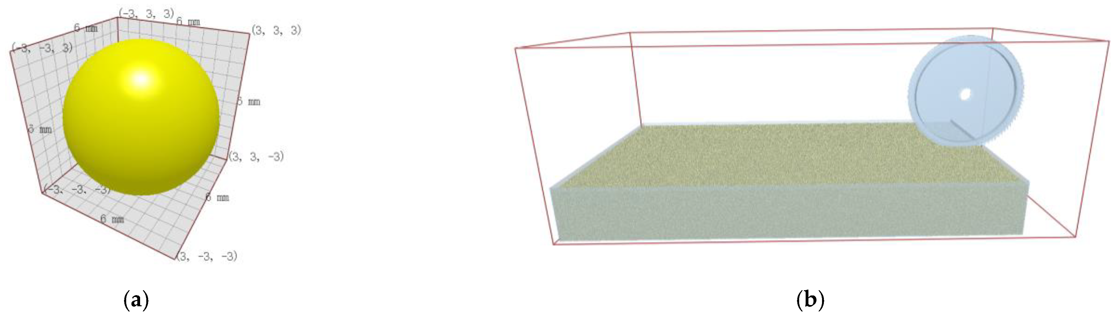
2.4. Discrete Element Modeling of the Motion Process of the Cotton-Picking Mechanism

2.4.1. Modeling and Parameter Setting of the Simulation Model

Due to the loose nature of the soil, the cotton-picking mechanism will unavoidably come into contact with the ground. An EDEM simulation test was performed to further analyze the force on the device’s serrated tooth end during operation. To precisely simulate the interaction between the picking device and the soil throughout the operation, the soil particle radius was set to 3 mm. The Hertz–Mindlin with bonding model was used to build the contact model of the soil particles in EDEM 2018 (DEM Solutions Ltd. Edinburgh, Scotland, UK). In order to accelerate the simulation calculation, we simplified the cotton-picking mechanism while retaining the serrated disc and ground wheel. We then used SolidWorks 2018 software (Dassault Systèmes S.E., Massachusetts, Concord, MA, USA) to build the simplified 3D model structure of the cotton-picking mechanism according to the 1:1 ratio, saved it as an “.x t” format file, and imported it into EDEM 2018 software.
The model of the soil trough was created in EDEM software with the dimension L × W × H = (2500 × 1000 × 250) mm. Figure 7 depicts the beginning state of the EDEM simulation model. The cotton-picking mechanism is placed at the soil trough’s upper right end. In order to imitate the actual motion law of the cotton-picking mechanism, the serrated disk is configured to rotate clockwise at 60 rpm with a constant speed to the left of 0.9 m/s and a sinking amount of 20 mm.
The simulation time step is set to 1.5 × 10⁻⁶, the simulation time is set to 2 s, and the grid cell size is three times the minimum soil particle size. The contact models were selected from soil–soil and soil–cotton-picking mechanisms. The main parameters included contact parameters (soil recovery coefficient, static friction coefficient, and dynamic friction coefficient) and intrinsic parameters (density, Poisson’s ratio, and shear modulus). The data of the main parameters of the discrete element method test model were obtained by the method of calibration and optimization of the discrete element parameters of clay loam soil from the stacking test [23,24,25], and the relevant parameters are shown in Table 2.

2.4.2. Analysis of Simulation Results

Figure 8 depicts the simulation result of the force on the serrated disk in the EDEM software once the simulation is complete. The result indicates that the maximum force exerted on the serrated disk upon entry into the soil is 201.88 N.
The strain and von Mises stress of the serrated tooth end under maximum force are analyzed using ANSYS software (ANSYS, Inc., Canonsburg, PA, USA). The load on the serrated tooth end is set to 201.88 N under the boundary condition of complete constraint at the center of the serrated disk, and the force is set opposite to the advancing direction of the serrated disk to bend it, and the force area is the working area of the serrated tooth end. In order to simplify the computation, the serrated tooth tip is assumed to experience a uniform load. Figure 9 illustrates the results. At the end of the saw tooth, there is a maximum strain of 0.023063 mm. The most significant equivalent force arises at the root of the serrated tooth, and the equivalent force is 64.677 MPa, which is much less than the yield strength of the serrated disk, 345 MPa. Therefore, the serrated disk’s structural strength meets the design’s requirements.

2.5. Test Materials

To test the reliability and operational efficiency of the cotton recovery device and to determine the optimal operating parameters, a field test was conducted at the Shihezi University test site in Shihezi, Xinjiang, on 3 October 2021.
The test was conducted in a cotton field after the cotton picker operation; the cotton variety was Xin Luzao 68. Cotton was planted in wide and narrow rows using a dense planting pattern (660 mm + 100 mm). The test plot was flat and ditchless, and the drip irrigation belt was recovered. The rated power of the employed tractor (KEER KE704B) was 51.5 kW. Test equipment included an electronic balance (HZ-C5033, the maximum weighing = 500 g, the minimum sense = 0.001 g), LJD15 meter ruler (range = 100 m), photoelectric tachometer (AR926, measurement range = 2.5–99,999 rpm), stopwatch, label paper, and encapsulated experimental bag.

2.6. Test Methods

Before machine operation, a test area of 50 m in length and 1.0 m in width was chosen in the test cotton field. Five points were chosen at random as testing points in the test area, with each testing point measuring 5 m in length. As the test result for this test area, the average value of the picking rate of the five testing points was used [26]. Before the test, five cotton field reference points with the same area as the test points were randomly selected, and all the fallen cotton in the reference points was manually recovered, and the average value of their masses was recorded as M1. After the machine operation, the mass of the missed cotton at the test points was manually recovered and cleaned up as M2, and the picking rate was calculated using Equation (13).
At the end of every test, five cotton samples weighing no less than 2000 g were picked randomly from various positions in the cotton collection box, concentrated, and thoroughly mixed. Then, five samples weighing 1000 g each were extracted. Manual removal of stalks, broken leaves, boll shells, and other impurities from the samples was conducted. The lint cotton was separated using the test gin while coarse impurities were collected. Lint cotton was then separated from cotton and impurities using a cotton impurity separator; the impurity rate of cotton was calculated using Equation (14). Finally, the impurity rate of each test was determined by averaging the results of five samples [27].
η 1 = M 1 M 2 M 1
η 2 = M d + M c + M x M y
where η1 is the picking rate of cotton (%); η2 is the impurities rate of cotton (%); M1 is the total mass of cotton in the testing points (g); M2 is the mass of cotton left in each testing point (g); Md is the mass of impurities, such as stalks, broken leaves, and boll shells picked out manually (g); Mc is the mass of impurities separated from the sample using the test gin (g); Mx is the mass of impurities separated from the lint in the sample using the cotton impurity separator (g); My is the mass of the sample (g).
Based on the structure parameters and operating characteristics of the device, the three critical parameters of machine operating speed, sawtooth disc speed, and sawtooth disc spacing were identified as the primary influencing factors of this test. A single-factor test was conducted to determine the effect of different levels of the same factor on the picking rate η1 and the impurity rate η2. Figure 10 illustrates the single-factor test’s results. When the operating speed of the machine increased, the picking rate showed a trend of first increasing and then decreasing, and the overall impurity rate showed an increasing trend; when the spacing of the serrated disc increased, the picking rate showed a continuous decreasing trend, and the impurity rate first decreased and then increased; when the speed of the serrated disc increased, the picking rate first increased and then decreased, and the overall impurity rate showed an increasing trend.
Therefore, 0.6, 0.9, and 1.2 m/s were selected as the factor levels of the operating machine speed, 40, 50, and 60 mm were selected as the factor levels of spacing between the serrated discs, and 40, 60, and 80 rpm were selected as the factor levels of the serrated disc speed, based on the premise of ensuring the picking rate and taking into account the impurity rate. Table 3 details the experiment with considered factors and level coding.

2.7. Test Results

Seventeen groups were administered a three-factor, three-level test based on the Box–Behnken test principle [28]. Table 4 shows the experimental protocol and results.

3. Results and Discussion

As shown in Table 5, we used Design Expert 13.0 software (Stat-Ease Inc., Minneapolis, MN, USA) to analyze the test results and the multiple regression fit. Table 5 shows the results of the picking rate and impurity rate variance analyses. The significance of the regression equations of η1 and η2 on X1, X2, and X3 was tested.
(1)
Establishment of the regression equation and significance analysis of the picking rate
The variance analysis for the picking rate indicated that in this regression model, X1, X3, X12, and X32 had an extremely significant impact on the picking rate model. X2 and X2 × 3 had a more significant impact on the picking rate model. The significance of the influence of each variable on the pickup rate was in the following order, from more to less significant: the serrated disc speed, the machine operation speed, and the spacing between serrated discs. After eliminating the insignificant factors, the quadratic regression equation of each variable on the picking rate was obtained [29], as shown in Equation (15):
η 1 = 80.88 + 1.36 X 1 + 0.8000 X 2 + 1.59 X 3 1.27 X 2 X 3 2.39 X 1 2 3.59 X 3 2
(2)
Establishment of the regression equation and significance analysis of the impurity rate
The variance analysis for the impurity rate indicated that the X2, X1 × 2, and X12 had an extremely significant impact on the impurity rate model. X1 had a significant impact on the impurity rate model. The significance of the influence of each variable on the impurity rate was in the following order, from more to less significant: the spacing between serrated discs, the machine operation speed, and the serrated disc speed. After eliminating the insignificant factors, the quadratic regression equation of each variable on the impurity rate was obtained as shown in Equation (16):
η 2 = 35.66 + 2.94 X 1 + 3.83 X 2 4.98 X 1 X 2 + 16.74 X 1 2

3.1. Response Surface Analysis

Using the 3D-surface response surface plots created by Design Expert 13.0.1.0, we analyzed the interactions between the parameters that affect the pickup and impurity rates of the cotton fallen on the ground (Figure 11).
(1)
Analysis of the influence of the picking rate
Figure 12a demonstrates that when X3 is fixed at 60 rpm and X1 is increased, the picking rate increases, then decreases, and the rate of decline becomes more gradual. When X2 increases, the picking rate increases gradually, with a moderate degree of change. Figure 12b shows that when X2 is fixed at 50 mm, X1 and X3 are increased, and the picking rate of cotton fallen on the ground increases initially and then decreases. Figure 12c indicates that when X1 controls 0.9 m/s, the pickup rate gradually grows as X2 increases, with a relatively flat amplitude of change; when X3 increases, the pickup rate gradually climbs and drops slowly.
Indeed, the faster the machine speed, the greater the weight of cotton hooked by the serrated teeth per unit of time, and the easier it is to fall off from the teeth, resulting in a lower pickup rate. When the distance between serrated discs is too tiny, adjacent saw discs quickly pick up the same piece of cotton, reducing the pickup rate. When the speed of the serrated disk increases, it is easy to tear the cotton when it touches the cotton so that only a tiny part of the serrated end is hooked, increasing the difficulty of picking [30]. Simultaneously, the centrifugal force on the landed cotton hooked by the serrated teeth increases accordingly, and the cotton fallen on the ground that is not hooked tightly is easily thrown away from the serrated disc.
(2)
Analysis of the influence of the impurity rate
Figure 12d indicates that when X3 is held constant at 60 rpm and X1 increases, the impurity rate drops and then increases with a significant trend. In addition, the rate of impurity gradually increases as X2 rises. Figure 12e demonstrates that when X2 is fixed at 50 mm, and X1 and X3 increase, the impurity rate increases and subsequently declines. Figure 12f demonstrates that when X1 is regulated to 0.9 m/s, the impurity rate grows gradually, with only minor variations. In addition, as X3 grows, the impurity rate reduces gradually and then rises gradually, with changes that are likewise relatively slow.
The reason for this is that the operating speed of the machine and the cotton falling to the ground are gradually matched to the optimal levels. In fact, as the speed increases, the amount of cotton picked by the device per unit of time increases, resulting in a high rate of impurities. When the spacing between serrated discs increases, the picking efficiency rises and more cotton enters the unloading mechanism, resulting in a relative increase in the impurity rate. Moreover, the faster the speed of the serrated disc, the greater the impurities on the hooked cotton due to the centrifugal force. Thus, impurities that adhere to the cotton can be easily thrown away. As the rotational speed increases, the conveying capacity of the serrated disc increases, preventing the majority of impurities from being thrown out and gathered directly, resulting in a high rate of impurities.

3.2. Parameter Optimization and Test Validation

In order to maximize the performance of the whole machine, the prototype’s influencing factors were optimized. Using Design Expert 13.0 software, the model was optimized and analyzed based on the operating conditions, performance requirements, and above-mentioned analysis results [31,32]. The software’s optimization conditions are set to dual-objective equal-weight optimization, and the constraints are as follows:
{ η 1 m a x = F ( X 1 , X 2 , X 3 ) η 2 m i n = F ( X 1 , X 2 , X 3 ) s . t { X 1 [ 0.6 , 1.2 ] X 2 [ 40.0 , 60.0 ] X 3 [ 40.0 , 80.0 ]
The objective function was optimized and solved. The optimal parameter combination was as follows: the optimized machine operating speed was 0.958 m/s, the optimized spacing between serrated discs was 40 mm, and the optimized serrated disc speed was 67.603 rpm. The predicted values of the cotton pickup and impurity rates were 81.01 and 33.79%, respectively. To verify the accuracy of the prediction model, a verification test was conducted, as shown in Figure 12. We took the operating machine speed of 0.96 m/s, the spacing between serrated discs of 40 mm, and the speed of the serrated disk at 68 rpm. We conducted five verification tests and took the average value. The results are shown in Table 6.
The difference between the experimental value and the theoretical optimization value of the model was less than 5% after verification. Therefore, the optimization model is reasonable and is capable of meeting operation requirements.

4. Conclusions

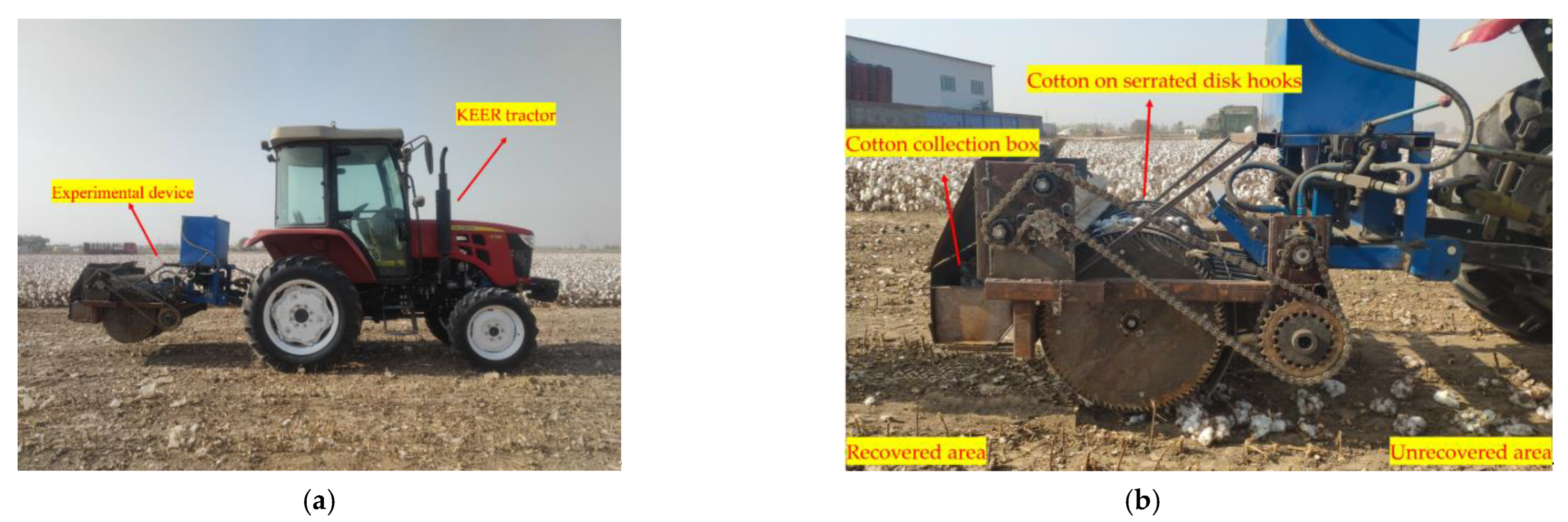
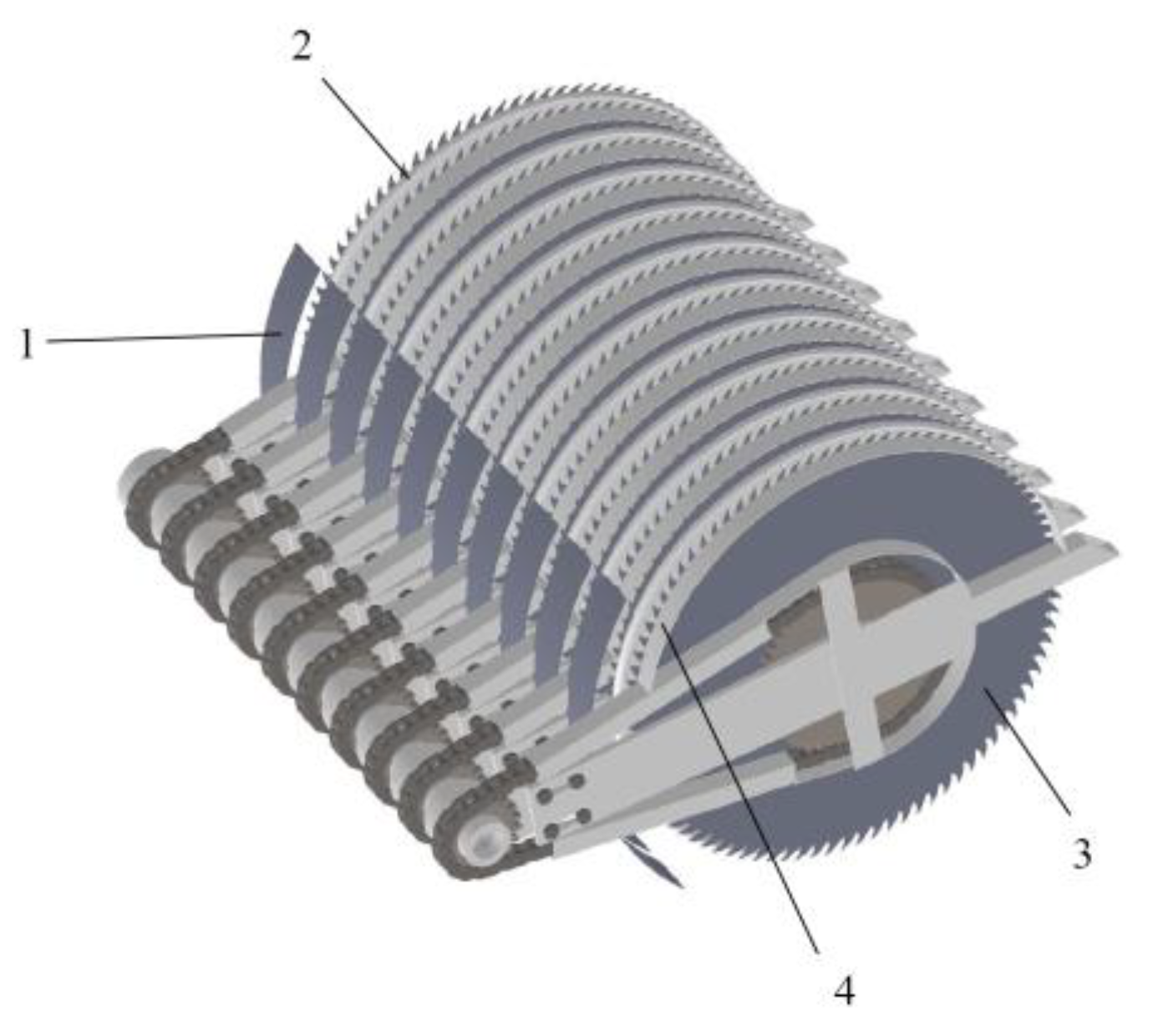
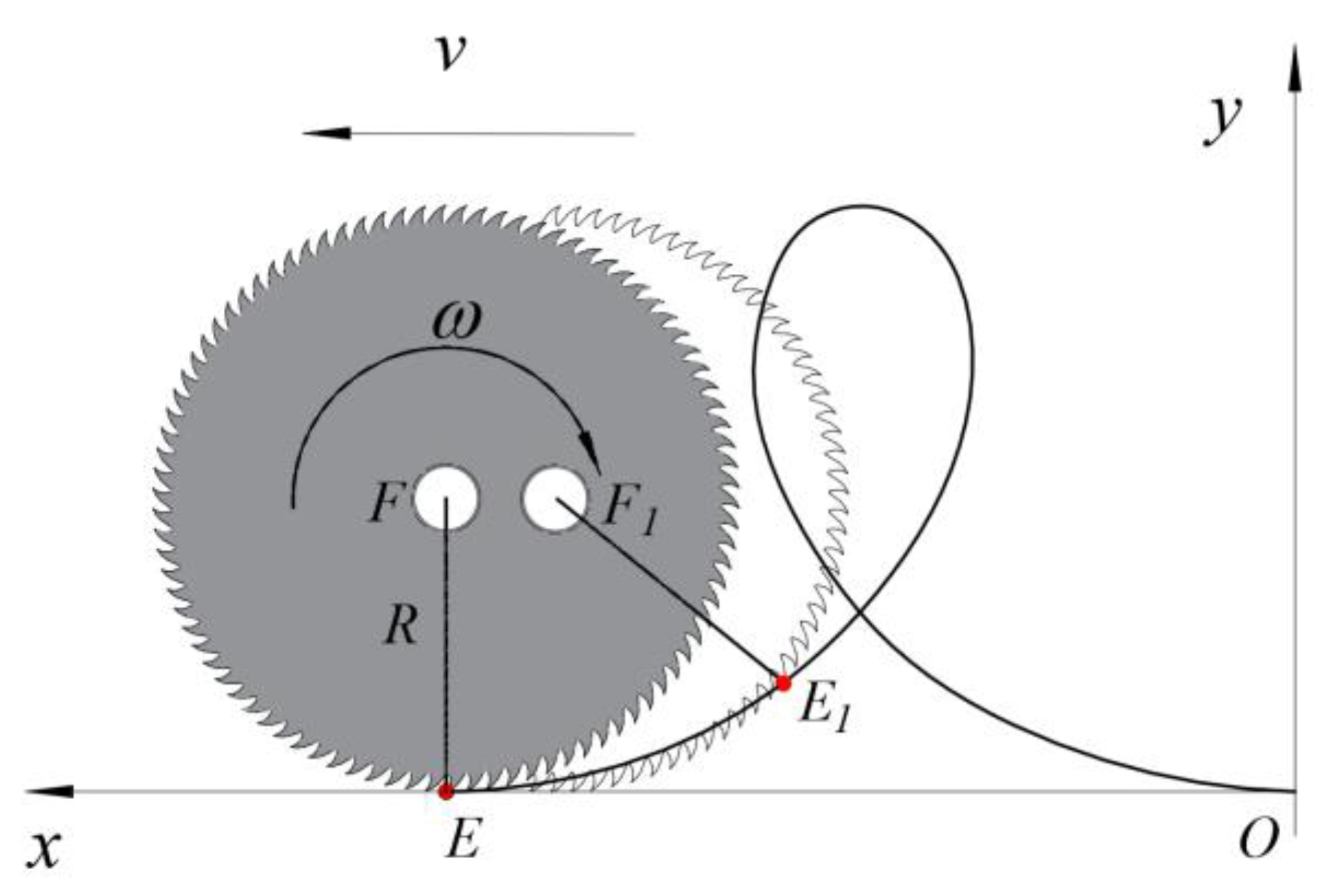
  • For cotton machine harvesting in Xinjiang, there was no suitable mechanism to recover cotton fallen on the ground. In this study, a sawtooth-type recovery device was designed to recover cotton fallen on the ground and efficiently unload it. The device consists of a sawtooth roll-tie-type cotton-picking mechanism, cotton unloading mechanism, cotton collection box, and other parts. The primary design parameters were determined using the analysis of the motion of the serrated discs, the cotton non-missing picking condition, and the cotton unloading condition.
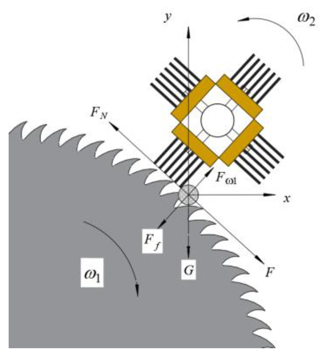
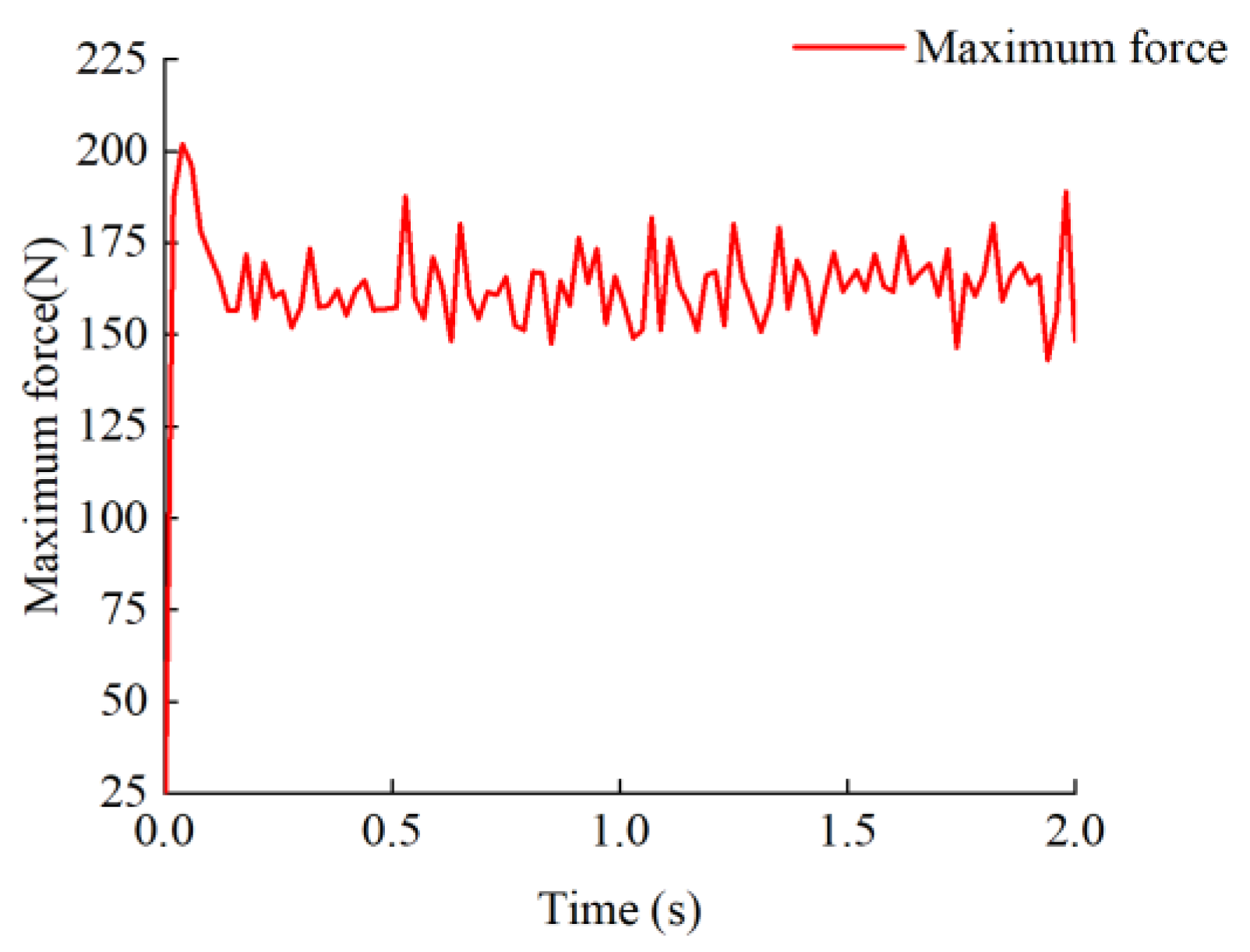
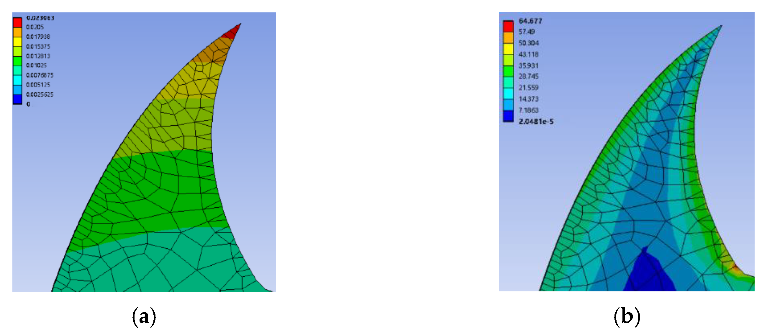
  • EDEM simulated the process of the cotton-picking mechanism movement. The maximum force on the tooth end of the serrated teeth was obtained during the working process. Then, ANSYS analysis of strain and stress on the tooth end of the serrated teeth was carried out to verify that the structural strength of the serrated disc meets the design requirements.
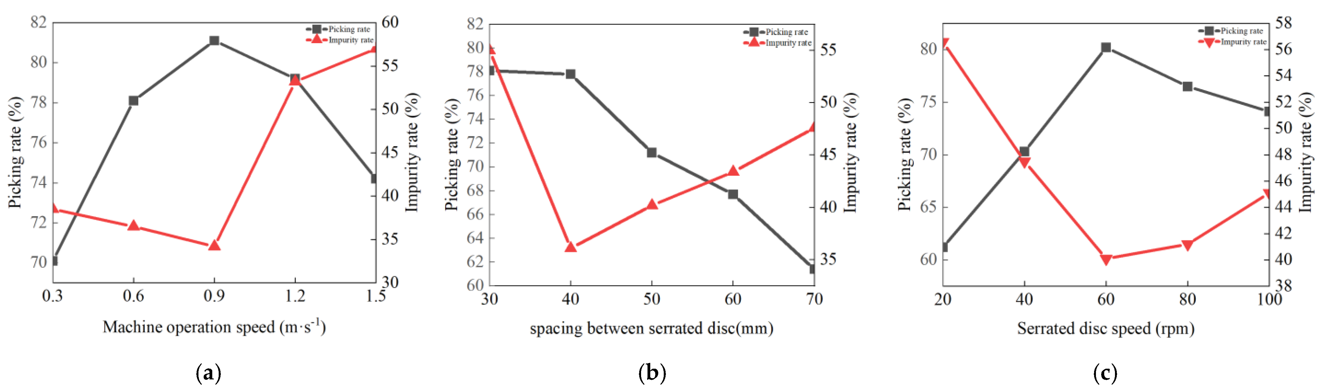
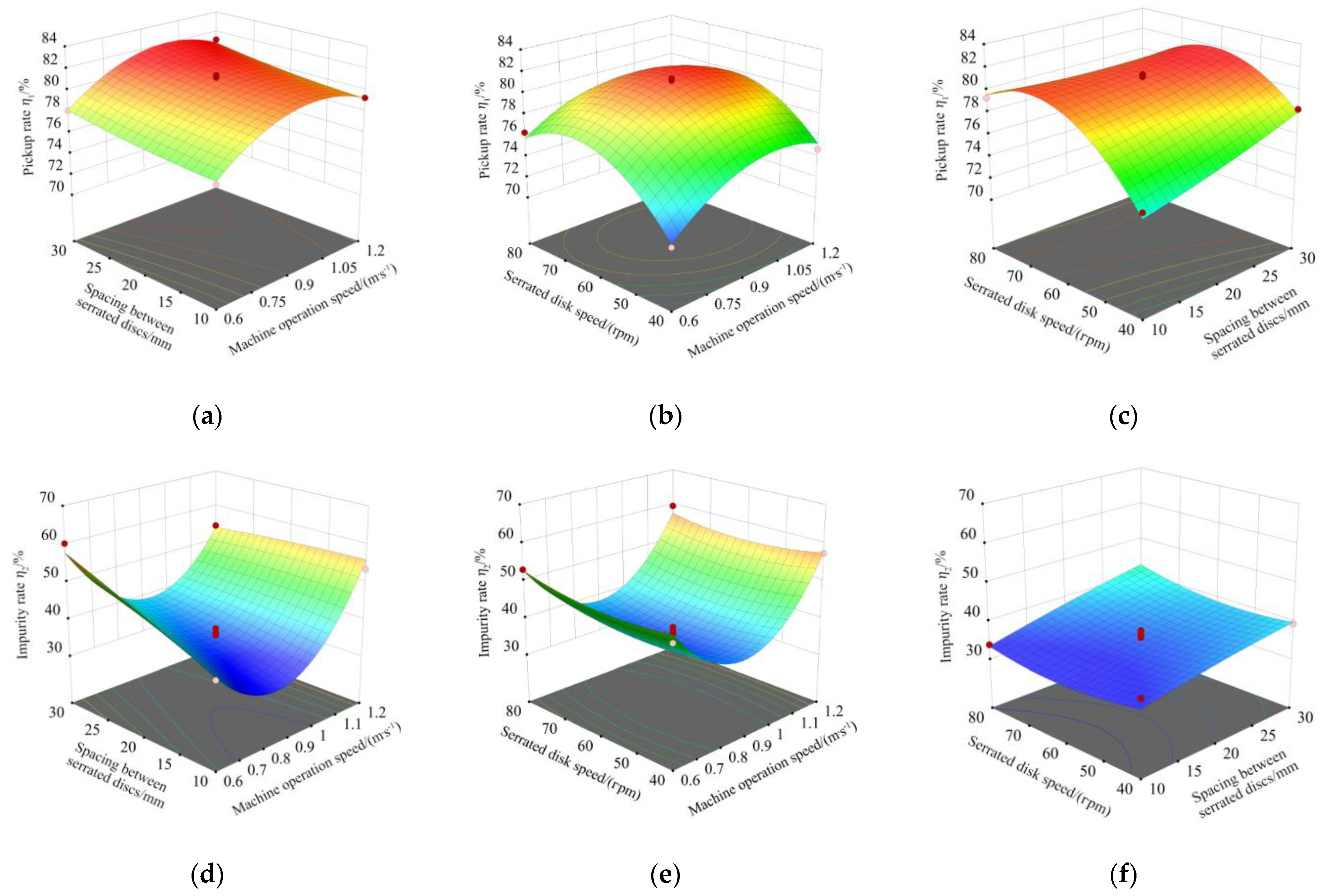
  • Considering the machine operating speed, spacing between serrated discs, and serrated disc speed as the experimental factors, the picking and impurity rates of the cotton fallen on the ground were used as the test indicators. Additionally, the response surface data were analyzed using Design Expert software, and multiple fittings obtained the regression equation of the picking and impurity rates. The influence of the interaction of various factors on the picking and impurity rates was determined.
  • Experimental tests on the device proved that when the optimized machine operating speed was 0.96 m/s, the spacing between serrated discs was 40 mm, and the speed of the serrated disc was 68 rpm. In addition, the picking and impurity rates of the cotton fallen on the ground were 79.09 and 35.12%, respectively. The optimized operating parameters were verified experimentally. Relative errors between the experimental results and optimized theoretical values of the picking and impurity rates were 2.37 and 3.79%, respectively, relatively small. Thus, the model was highly reliable.

Author Contributions

Conceptualization, methodology, writing—original draft, H.W. and S.C.; writing—review and editing, S.C. and Y.Y.; software, H.W. and Y.L.; investigation, H.W. and Y.L.; data curation, X.M. and P.J.; funding acquisition, S.C.; validation, Y.Y. All authors have read and agreed to the published version of the manuscript.

Funding

This research was funded by Corps Young and Middle-aged Leading Talents Program Project (2018CB011).

Institutional Review Board Statement

Not applicable.

Informed Consent Statement

Not applicable.

Data Availability Statement

All relevant data presented in the article are stored according to institutional requirements and, as such, are not available online. However, all data used in this manuscript can be made available upon request to the authors.

Conflicts of Interest

The authors declare no conflict of interest.

References

  1. Jie, Z. The Research On Environment Cost in Cotton Production in Xinjiang. Master’s Thesis, Tarim University, Tarim, China, 2014. [Google Scholar]
  2. Abdelraheem, A.; Esmaeili, N.; O’Connell, M.; Zhang, J. Progress and perspective on drought and salt stress tolerance in cotton. Ind. Crops Prod. 2019, 130, 118–129. [Google Scholar] [CrossRef]
  3. ShuXun, Y.; Shuli, F.; Hantao, W.; Hengling, W.; Chaoyou, P. Progresses in Research on Cotton High Yield Breeding in China. Sci. Agric. Sin. 2016, 49, 3465–3476. [Google Scholar] [CrossRef]
  4. Wang, Y.C.; Peng, S.B.; Huang, J.L.; Zhang, Y.L.; Feng, L.; Zhao, W.Q.; Qi, H.K.; Zhou, G.S.; Deng, N.Y. Prospects for cotton self-sufficiency in China by closing yield gaps. Eur. J. Agron. 2022, 133, 126437. [Google Scholar] [CrossRef]
  5. Khan, N.; Han, Y.; Xing, F.; Feng, L.; Wang, Z.; Wang, G.; Yang, B.; Fan, Z.; Lei, Y.; Xiong, S. Plant Density Influences Reproductive Growth, Lint Yield and Boll Spatial Distribution of Cotton. Agronomy 2020, 10, 14. [Google Scholar] [CrossRef] [Green Version]
  6. Aslam, S.; Khan, S.H.; Ahmed, A.; Dandekar, A.M. The tale of cotton plant: From wild type to domestication, leading to its improvement by genetic transformation. Am. J. Mol. Biol. 2020, 10, 91–127. [Google Scholar] [CrossRef] [Green Version]
  7. Beibei, Z.; Wei, G.; Jianyu, C.; Kangguo, M.; Ying, M.; Lin, H. Assessment of the Biomass Energy Use Potential of Cotton Byproducts in China. Cotton Sci. 2016, 28, 384–391. [Google Scholar] [CrossRef]
  8. Tingguan, C.; Hongwen, Z.; Lei, W.; Longchang, Z.; Jun, W.; Jianxin, L.; Yanqing, G. Optimization and experiments of picking head transmission system of horizontal spindle type cotton picker. Trans. Chin. Soc. Agric. Eng. 2020, 36, 18–26. [Google Scholar] [CrossRef]
  9. Cheng, W.M.; Wang, L. How to reduce the cost of cotton cultivation? A Case Study of Xinjiang, China. Custos E Agronegocio Line 2019, 15, 458–470. [Google Scholar]
  10. Xiuru, L.; Xiaoyue, J.; Jiahui, N. The Present Situation and Prospects of Cotton Industry Development in China. The Present Situation and Prospects of Cotton Industry. Sci. Agric. Sin. 2018, 51, 26–36. [Google Scholar] [CrossRef]
  11. Chengling, Z.; Tianhui, L.; Jianyu, L. Detection of Impurity Rate of Machine-Picked Cotton Based on Improved Canny Operator. Electronics 2022, 11, 974. [Google Scholar] [CrossRef]
  12. GB/T 21397-2008; Cotton Harvester. Agriculture Machinery of Standardization Administration of China. China Standard Press: Beijing, China, 2018.
  13. Statistical Bureau of the People’s Republic of China. China Statistical Yearbook; China Statistics Press: Beijing, China, 2021. [Google Scholar]
  14. Lindsey, M.; Charles, S.C.; Joe, E. Mechanical gleaning and ginning of ground-loss cotton in the Yazoo-Mississippi Delta. 1969. Available online: https://scholarsjunction.msstate.edu/cgi/viewcontent.cgi?article=1074&context=mafes-bulletins (accessed on 20 March 2022).
  15. Lehman, L.A. Ground Cotton Retriever with Dual Cleaning Means. 1985. Available online: https://patents.google.com/patent/US4497088 (accessed on 5 March 2022).
  16. Jianlong, H.; Xiaolong, H. Air Suction Type Picking Machine for Cotton Falling on Ground. 2022. Available online: https://patents.google.com/patent/CN215380014U (accessed on 8 March 2022).
  17. Shi, G.; Li, J.; Kan, Z.; Ding, L.; Ding, H.; Zhou, L.; Wang, L. Design and Parameters Optimization of a Provoke-Suction Type Harvester for Ground Jujube Fruit. Agriculture 2022, 12, 409. [Google Scholar] [CrossRef]
  18. Guangli, S.; Liyong, S.; Kun, L. Machine for Picking Cotton Falling to Ground. 2021. Available online: https://patents.google.com/patent/CN214102380U (accessed on 8 March 2022).
  19. Changlin, C.; Lei, S.; Yutong, Z.; Senlin, M.; Yongfei, S.; Mingsen, H. Design and experiment of the MQZ-4A type site cotton pre-processor. J. Chin. Agric. Mech. 2015, 36, 17–19. [Google Scholar] [CrossRef]
  20. Huang, M.; Shi, L.; Zhang, Y.; Chen, C.; Sun, Y.; Xie, Q.; Kong, F. Optimization experiment of machine-mounted seed cotton pre-treatment apparatus for cotton stripper harvester. Trans. Chin. Soc. Agric. Eng. 2016, 32, 21–29. [Google Scholar] [CrossRef]
  21. Hu, W.; Chen, X.; Wang, J.; Li, Y. Construction and finite element simulation of the saw type gin stand using fractal theory. Text. Res. J. 2020, 90, 2755–2768. [Google Scholar] [CrossRef]
  22. Le, S. Cleaning performance of modified cylinder cleaners. J. Cotton Sci. 2006, 10, 273–283. [Google Scholar]
  23. Zhong, W.Q.; Yu, A.B.; Liu, X.J.; Tong, Z.B.; Zhang, H. DEM/CFD-DEM Modelling of Non-spherical Particulate Systems: Theoretical Developments and Applications. Powder Technol. 2016, 302, 108–152. [Google Scholar] [CrossRef]
  24. Wu, T.; Huang, W.F.; Chen, X.S.; Ma, X.; Han, Z.Q.; Pan, T. Calibration of discrete element model parameters for cohesive soil considering the cohesion between particles. J. South China Agric. Univ. 2017, 38, 93–98. [Google Scholar] [CrossRef]
  25. Xianlinang, W.; Hong, H.; Qingjie, W.; Hongwen, L.; Jin, H.; Wanzhi, C. Calibration method of soil contact characteristic parameters based on DEM theory. Trans. Chin. Soc. Mach. 2017, 48, 78–85. [Google Scholar]
  26. Jianhua, X.; Yuxin, Y.; Silin, C.; Yi, Z.; Yabin, Z.; Weibin, M. Design and experiments of rake type surface residual film recycling machine with guide chain. Trans. Chin. Soc. Agric. Eng. 2020, 36, 76–86. [Google Scholar] [CrossRef]
  27. Mingsen, H.; Lei, S.; Yutong, Z.; Changlin, C.; Yongfei, S.; Qing, X.; Fanting, K.; Chongyou, W. Revised design and experiments on brush-rolling cotton harvester. Trans. Chin. Soc. Agric. Eng. 2017, 33, 41–47. [Google Scholar] [CrossRef]
  28. Sohail, Y.; Parag, B.; Nemeshwaree, B.; Giorgio, R. Optimizing Organophosphorus Fire Resistant Finish for Cotton Fabric Using Box-Behnken Design. Int. J. Environ. Res. 2016, 10, 313–320. [Google Scholar] [CrossRef]
  29. Xuejun, Z.; Jiaqiang, L.; Zenglu, S.; Wei, J.; Jinshan, Y.; Mengjie, Y. Design and parameter optimization of reverse membrane and soil separation device for residual film recovery machine. Trans. Chin. Soc. Agric. Eng. 2019, 35, 46–55. [Google Scholar] [CrossRef]
  30. Wen, H.; Di, W.; Xiaochuan, C.; Jun, W.; Yong, L. Finite element simulation of cotton serrated ginning state based on cottonseed modeling. J. Text. Res. 2020, 41, 27–32. [Google Scholar] [CrossRef]
  31. Wei, Y.; Zhichao, H.; Nu, W.; Hongbo, X.; Zhaoyan, Y.; Xinxing, Z. Parameter optimization and experiment for plastic film transport mechanism of shovel screen type plastic film residue collector. Trans. Chin. Soc. Agric. Eng. 2017, 33, 17–24. [Google Scholar] [CrossRef]
  32. Lili, S.; Zhichao, H.; Fengwei, G.; Feng, W.; Penglai, W. Design and parameter optimization on teeth residue plastic film collector of ridged peanut. Trans. Chin. Soc. Agric. Eng. 2017, 33, 8–15. [Google Scholar] [CrossRef]
Figure 1. Cotton recovery device: 1. frame; 2. hydraulic device; 3. hangers; 4. hydraulic motor; 5. sprockets; 6. straw shield; 7. sawtooth roll-tie cotton-picking mechanism; 8. cotton collection box; and 9. cotton unloading mechanism. (a) Structure diagram of the cotton recovery device. (b) Schematic diagram of the principle of the cotton recovery device.
Agriculture 12 01296 g001
Figure 2. Sawtooth roll-tie-type cotton-picking mechanism: 1. straw shield; 2. ground wheel; 3. serrated disc; 4. guard ring.
Agriculture 12 01296 g002
Figure 3. Motion trajectory of the serrated tooth end.
Agriculture 12 01296 g003
Figure 4. Adjacent serrated tooth end motion trajectory. v is the operating speed of the machine (m/s); ω is the angular speed of the serrated disc, (rad·s−1); O, O1, and O2 are the centers of rotation of the serrated disc at different moments; E is the initial point of the serrated tooth end into the cotton; E1 is the deepest point of the serrated tooth end into the cotton; E2 is the point of the serrated tooth end out of the cotton; E′ is the point of the adjacent serrated tooth end into the cotton; vt1 is the displacement of the rotary center of the previous serrated tooth in time t1 (mm); vt2 is the displacement of the rotary center of the latter saw tooth in time t2 (mm).
Agriculture 12 01296 g004
Figure 5. 1. Brush strip; 2. drive shaft; 3. spikes; and 4. unloading the cotton shaft.
Agriculture 12 01296 g005
Figure 6. Force analysis of cotton. ω1 and ω2 are the rotational angular speed of the serrated disk and brush roller, respectively (rad/s); Ff is the force of the serrated teeth on the cotton (N); F is the force of the brush roller on the cotton (N); θ is the angle between the force of the brush roller on the cotton and its own gravity (°); F1 is the centrifugal force on the cotton (N); FN is the support force of the serrated teeth on the cotton (N); and G is the gravity of the cotton (N).
Agriculture 12 01296 g006
Figure 7. Particle and geometric simulation model. (a) Particle model of the soil; (b) simulation model of the EDEM.
Agriculture 12 01296 g007
Figure 8. Variation of force on serrated disc with time.
Agriculture 12 01296 g008
Figure 9. Analysis results. (a) Serrated disc tooth strain model; (b) Serrated disc tooth stress model.
Agriculture 12 01296 g009
Figure 10. Single factor test. (a) The effect of machine operation speed on the operating effect. (b) The effect of spacing between serrated discs on the operating effect. (c) The effect of the serrated disc speed on the operating effect.
Agriculture 12 01296 g010
Figure 11. Field test of the experimental device. (a) Field test. (b) Device operation effect.
Agriculture 12 01296 g011
Figure 12. Effects of the interaction of various factors on the picking rate and trash content of cotton fallen on the ground. (a). η1 = (X1, X2, 60); (b). η1 = (X1, 50, X3); (c). η1 = (0.9, X2, X3); (d). η2 = (X1, X2, 60); (e). η2 = (X1, 50, X3); (f). η2 = (0.9, X2, X3).
Agriculture 12 01296 g012
Table 1. Main technical parameters of the cotton recovery device.
ParameterValue
Structure formTraction type
Overall dimension (length × width × height)/mm1670 × 1240 × 1550
Engine rated power/kW51.5
Effective working width/mm1000
Picking rate/%≥75
Impurity rate/%40≤
Table 2. Simulation parameter settings of soil particles and geometry.
ItemParameterValue
Soil particlesPoisson’s ratio0.30
Shear modulus/Pa5 × 107
Density/(kg·m−3) 2600.00
Cotton-picking mechanismPoisson’s ratio0.30
Shear modulus/Pa7.90 × 1010
Density/(kg·m−3) 7850.00
Particle−ParticlesRecovery coefficient0.21
Static friction coefficient0.68
Dynamic friction coefficient 0.27
Particle−Cotton-picking mechanismRecovery coefficient0.54
Static friction coefficient0.53
Dynamic friction coefficient 0.13
Table 3. Test factors and levels.
Coded
Value
Machine Operation Speed X1 (m·s−1)Spacing between Serrated Discs X2 (mm)Serrated Disc Speed X3 (rpm)
−10.64040
00.95060
11.26080
Table 4. Test plans and results.
Test X1X2X3η1η2
101178.140.1
200081.436.5
3−11078.160.3
4−10−171.148.3
510−174.757.4
600080.637.6
700079.934.7
81−1079.353.6
900081.333.8
1011081.254.3
11−1−1076.339.7
1201−178.339.4
1310177.559.6
1400081.235.7
150−1−174.436.4
160−1179.333.8
17−10176.353.1
Table 5. Analysis of variance of regression equation.
Source of
Variation
DOFPicking Rate η1/%Impurity Rate η2/%
Sum of SquaresFSignificant Level pSum of SquaresFSignificant Level p
Models9130.4730.89<0.0001 **1514.9526.680.0001 **
X1114.8531.640.0008 **69.0310.940.0130 *
X215.1210.910.0131 *117.0518.550.0035 **
X3120.1642.960.0003 **3.250.51530.4961
X1 × 210.00250.00530.943999.0015.690.0055 **
X1 × 311.443.070.12331.690.26790.6207
X2 × 316.5013.850.0074 *2.720.43150.5322
X12124.0551.240.0002 **1180.61187.12<0.0001 **
X2210.23250.49540.50430.77850.12340.7357
X32154.27115.62<0.0001 **20.293.220.1160
Residual73.29 44.16
Lack of fit31.701.430.395435.315.320.0701
Pure error41.59 8.85
Total16133.75 1559.12
Note: ** means highly significant (p < 0.01), and * means significant (0.01 ≤ p < 0.05).
Table 6. Comparison between the optimum theoretical and test results.
ParameterPicking Rate η1/%Impurity Rate η2/%
Theoretical optimization value81.0133.79
Test average79.0935.12
Relative error2.373.79
Publisher’s Note: MDPI stays neutral with regard to jurisdictional claims in published maps and institutional affiliations.

