Article

Numerical and Experimental Investigations of Humeral Greater Tuberosity Fractures with Plate Fixation under Different Shoulder Rehabilitation Activities

1
Department of Mechanical Engineering, National Taiwan University of Science and Technology, Taipei 106, Taiwan
2
Graduate Institute of Applied Science and Technology, National Taiwan University of Science and Technology, Taipei 106, Taiwan
*
Author to whom correspondence should be addressed.
Appl. Sci. 2022, 12(13), 6802; https://doi.org/10.3390/app12136802
Submission received: 9 June 2022 / Revised: 24 June 2022 / Accepted: 4 July 2022 / Published: 5 July 2022
(This article belongs to the Special Issue Recent Advance in Finite Elements and Biomechanics)

Abstract

:
The incidence of humerus greater tuberosity (GT) fractures is about 20% in patients with proximal humerus fractures. This study aimed to investigate the biomechanical performances of the humerus GT fracture stabilized by a locking plate with rotator cuff function for shoulder rehabilitation activities. A three-dimensional finite element model of the GT-fracture-treated humerus with a single traction force condition was analyzed for abduction, flexion, and horizontal flexion activities and validated by the biomechanical tests. The results showed that the stiffness calculated by the numerical models was closely related to that obtained by the mechanical tests with a correlation coefficient of 0.88. Under realistic rotator cuff muscle loading, the shoulder joint had a larger displacement at the fracture site (1.163 mm), as well as higher bone stress (60.6 MPa), higher plate stress (29.1 MPa), and higher mean screw stress (37.3 MPa) in horizontal flexion rehabilitation activity when compared to that abduction and flexion activities. The horizontal flexion may not be suggested in the early stage of shoulder joint rehabilitation activities. Numerical simulation techniques and experimental designs mimicked clinical treatment plans. These methodologies could be used to evaluate new implant designs and fixation strategies for the shoulder joint.

Graphical Abstract

1. Introduction

The greater tuberosity (GT) fracture is one of the common proximal humerus fractures. Around 20% of patients with proximal humerus fractures have GT fractures [1]. The GT is the attachment site for the supraspinatus, infraspinatus, and teres minor muscles of the rotator cuff. Shoulder functions deteriorate after the GT fracture has occurred. Avulsion-type and split-type GT fractures in which the fractured fragments are separated require orthopedic surgery for fracture reduction and fixation [2]. Locking plates or screw fixation are common treatment methods for the greater tuberosity fracture [3,4,5,6]. However, the risk of the axillary nerve and deltoid muscle damage is increased during the treatment with locking plate fixation [3,5,6,7].
Studies conducted in the past have evaluated and compared various treatment methods for the GT fracture through clinical trials [3,4,5,6], in vitro experiments [8,9,10,11,12,13,14], and computational simulations [15,16,17,18]. There are, however, variations in fracture pattern and individual condition of patients, bone mineral density and geometry, and size of specimens that may affect the evaluation of various fixation strategies [19,20,21]. Furthermore, the shoulder joint has a high degree of mobility. Therefore, it is essential to consider shoulder movements as well when evaluating various fixation strategies for GT fractures. Biomechanical behaviors in the different fields of modern medicine have been extensively investigated by means of computer-aided design and finite element method [22,23,24,25]. With the use of these techniques in the present study, the humerus GT fracture model with plate fixation was analyzed under mechanical testing loading and realistic rotator cuff muscle loading.
The objective of this study was to compare, biomechanically, the effects of shoulder rehabilitation activities on the humerus GT fracture stabilized by a locking plate with rotator cuff function. A three-dimensional finite element model of the GT fractured humerus with a locking plate was modeled and analyzed numerically. To understand the impact of shoulder rehabilitation activities on plate fixation for GT fracture, we considered three types of shoulder rehabilitation activities including abduction, flexion, and horizontal flexion (Figure 1). The numerical model with a single traction force condition was validated by biomechanical tests. The validated numerical model was used to apply rotator cuff muscle forces to calculate displacement at the fracture site, bone stress, plate stress, and mean screw stress. The null hypothesis was that there would be no difference in the biomechanical behavior of the shoulder joint with GT fracture fixation with locking plates for the different rehabilitation activities.

2. Materials and Methods

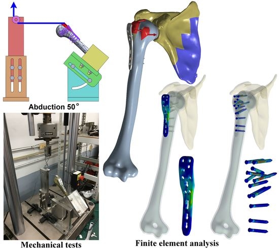
2.1. Numerical Modeling of Humerus GT Fracture with Plate Fixation under Mechanical Testing Loading

Initially, a three-dimensional solid model of the intact humerus used in the present study was originally developed by a commercial company (Zygote Media Group, Inc., American Fork, UT, USA). This commercially available Zygote solid skeleton model was modified using SolidWorks 2019 (SolidWorks Corporation, Concord, MA, USA) and trimmed to separate the cortical and cancellous bones using Geomagic Freeform (3D Systems, Rock Hill, SC, USA). In this study, the GT fracture model of the humerus was based on a split-type fracture proposed by Mutch et al. [2]. Thus, an osteotomy was performed such that the GT bone was completely separated. The PHILOS proximal humeral internal locking plate from DePuy Synthes (Zuchwil, Switzerland) was modeled in SolidWorks 2019, and implanted using locking screws in the aforementioned GT fracture model according to the clinician’s guidance. The humerus bone plate construct was imported into a commercial finite element analysis software ANSYS Workbench 19.2 (ANSYS Inc., Canonsburg, PA, USA) for computational analysis (Figure 2). The materials of cortical bone, cancellous bone, and titanium plate and screws were assumed to be homogeneous, isotropic, and linearly elastic. The elastic moduli of 12, 0.1, and 110 GPa were assigned to the cortical bone, cancellous bone, and implants, respectively. A Poisson’s ratio of 0.3 was also applied to all the materials [15]. The bone and implants were free meshed with higher order 10 node tetrahedral elements due to the complex geometry, and a convergence study was performed to confirm the accuracy of the numerical models. Frictionless contact was assigned to the interfaces between the humerus and GT fractured fragment, and between the locking plate and humerus. The bonding constraint was specified to the interfaces between the screws and surrounding bone, and between the plate and screw heads to simulate tightened locking. The distal humerus was fixed in all degrees of freedom and a quantitative displacement of 5 mm was applied to the proximal humeral head to observe the reaction force. The stiffness of the model was calculated from the observed reaction force and displacement for the humerus positions, defined relative to the vertical plane of 15, 50, and 90° for abduction and flexion motions and 35, 60, and 90° for horizontal flexion motion [26]. All flexion motions are same as for the horizontal flexion at 90°.

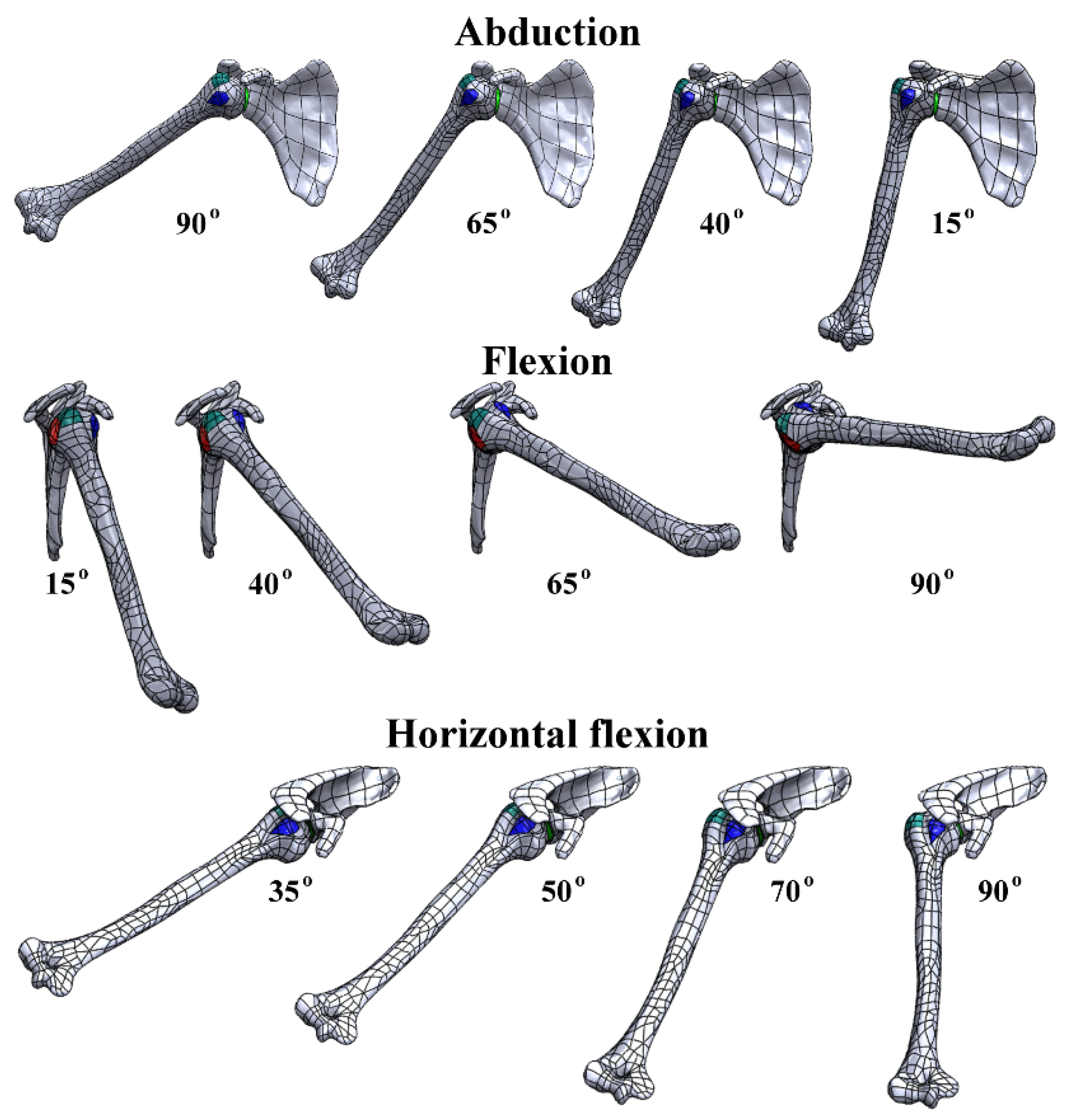
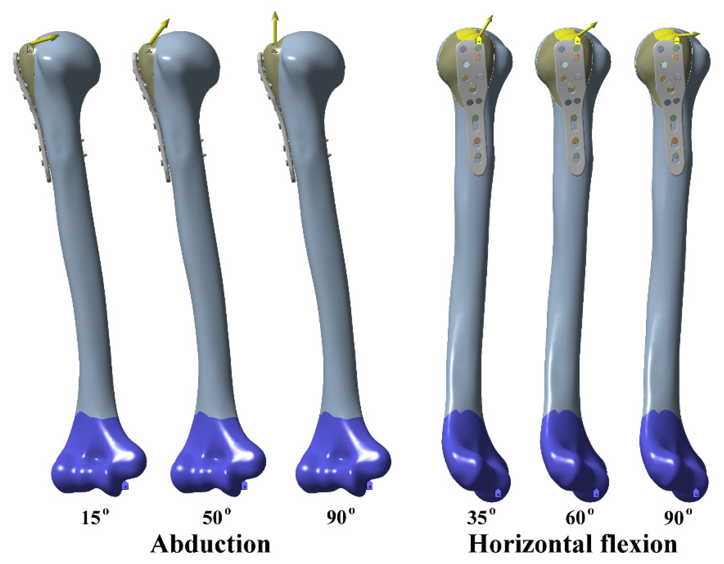
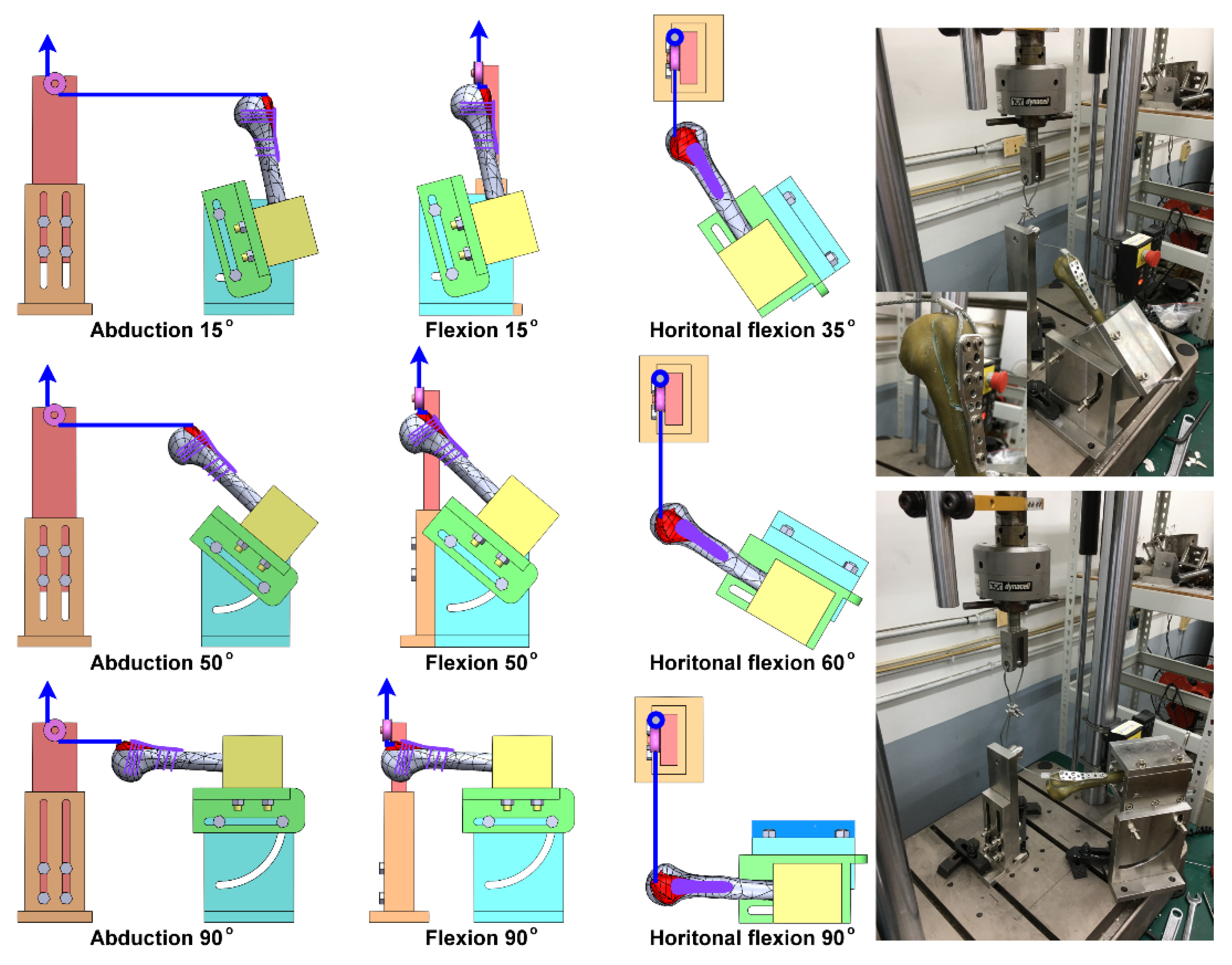
2.2. Mechanical Tests of Shoulder Rehabilitation Activities

Artificial medium-sized fourth-generation composite humeri (Sawbones, Pacific Research Laboratories, Inc., Vashon, WA, USA) were used for the mechanical experiments. Artificial humeral bones enable more accurate comparisons of biomechanical properties because their geometries and material properties are more consistent with human bones. A GT fracture was recreated in the artificial humerus using a reciprocating saw with a thin blade and a fracture was repaired using a titanium locking plate and locking screws. The geometry and size of the fixation implant were similar to those used in our finite element model. The plate bone construct was positioned in the custom-made fixture, specially designed based on previous studies from literature for mechanical testing [21,27]. The tensile force simulating the supraspinatus and infraspinatus muscle tension on the greater tuberosity was applied to the GT fracture fragment by a servo-hydraulic material testing machine (model 8872; Instron Industrial Products Group, Grove City, PA, USA) through a stainless steel cable (Figure 3). This setup was designed to be adjustable, so the traction force direction can be changed for different abduction, flexion, and horizontal flexion positions. The plate bone construct positions of 15, 50, and 90° for abduction and flexion motions and the positions of 35, 60, and 90° for horizontal flexion motion were considered and experimented on. The static loading tests were conducted by applying a tensile ramp-up load with a loading rate of 1 mm/min in displacement control mode and the tests were terminated when the displacement of the actuator reached 5 mm. The test was repeated six times for each condition. The load–displacement curve of different configurations was recorded, and stiffness of each specimen was calculated.

2.3. Statistical Analysis

The mechanical test results were statistically compared in each situation using a one-way analysis of variance (ANOVA), (SPSS v19.0., SPSS Inc., Chicago, IL, USA) with Bonferroni post hoc tests. The level of significance was defined when p < 0.05. Correlation analysis was performed between the stiffness obtained from finite element models and that obtained from the mechanical tests.

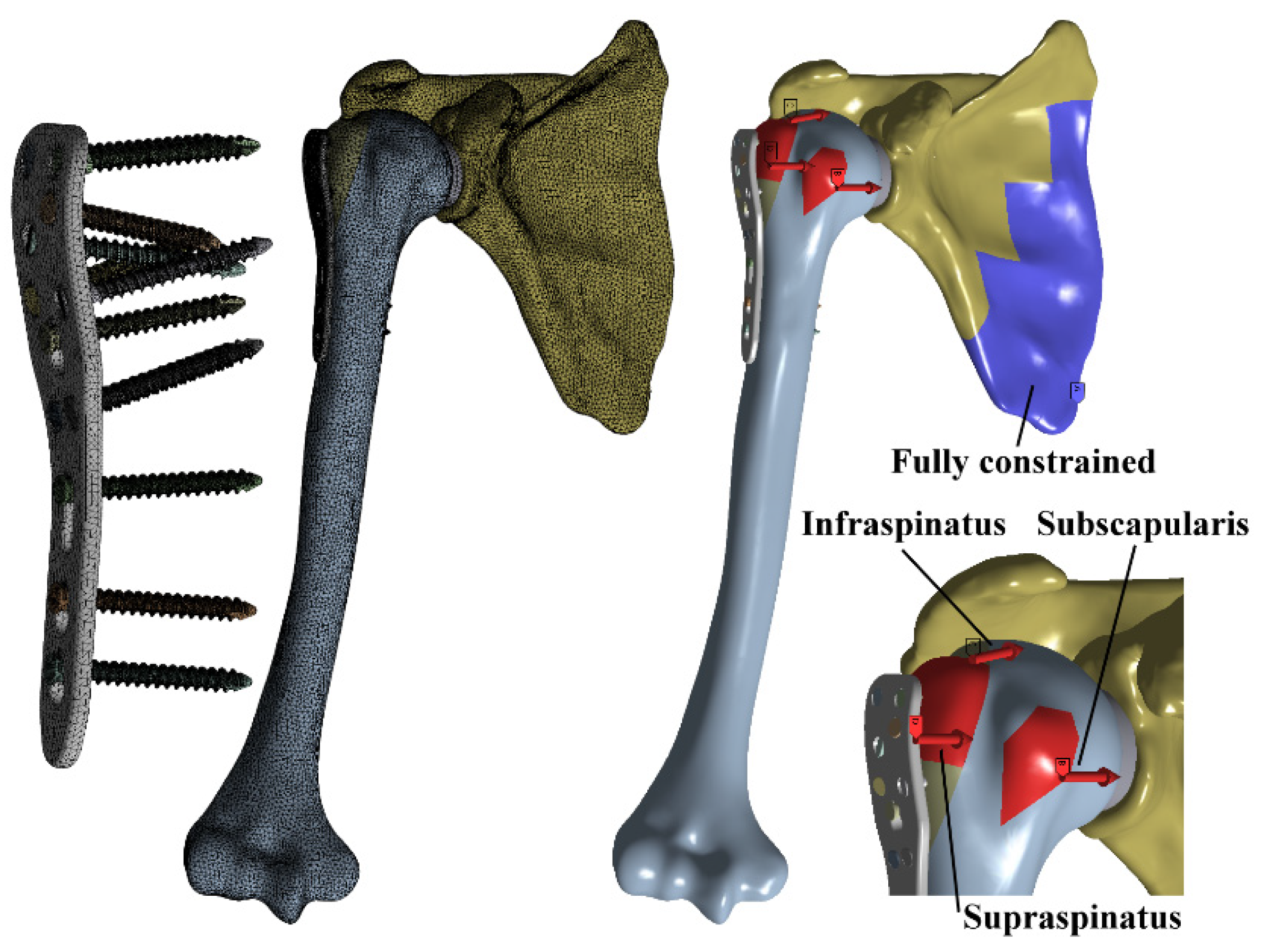
2.4. Numerical Modeling of Injured Shoulder Joint with Plate Fixation under Realistic Rotator Cuff Muscle Loading

A three-dimensional shoulder joint model consisting of the humerus and scapula was generated based on the commercial Zygote solid skeleton model to mimic healthy adult male shoulder joints. SolidWorks 2019 was used to reconstruct the shoulder joint model including three rotator cuff muscles, namely the supraspinatus, infraspinatus, and subscapularis, that connect the humerus to the scapula to simulate the muscle forces to the shoulder based on Curtis et al. study [28]. The GT osteotomy and its treatment with a locking system was done as in the previously analyzed humerus model in this study. The shoulder joint activities positions of 15, 40, 65°, and 90° for abduction and flexion motions and 35, 50, 70, and 90° for horizontal flexion motion were developed based on Wu et al.’s study [26]. The loading orientation of the shoulder joint muscle forces was defined based on their muscle attachment sites, and the orientation was defined using a local coordinate system. The shoulder joint models with the locking plate and screw construct were also computationally analyzed using ANSYS Workbench 19.2. A similar meshing method and materials properties were used as in the humerus model (Figure 4). Frictionless contact was defined between the humerus head and scapula, while for the other components of the model, it was the same as in the previous humerus model analysis. For the loading condition, three types of the rotator cuff muscle forces including the subscapularis, supraspinatus, and infraspinatus were applied, whereas the lower part of the scapula was fixed in all degrees of freedom for the boundary condition. Maximum deformation at the fracture site, maximum bone stress, maximum plate stress, and mean screw stress were recorded to evaluate the fixation stability, risk of secondary bone damage, and risk of bone implant failure after fracture fixation surgery, respectively.

3. Results

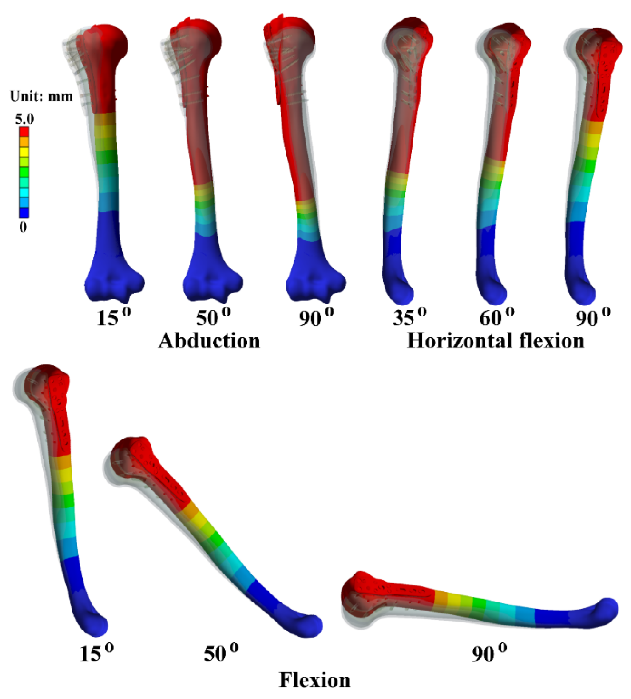
3.1. Finite Element Simulation under Mechanical Testing Loadings

The finite element model of the humerus bone with the locking plate was analyzed successfully and its results were converged properly after the convergence analysis. Under loading, the humerus underwent flexural deformation at 15° abduction motion, and gradually transitioned to axial deformation as the abduction angle increased to 50 and 90°. For all the positions of flexion, the humerus resulted the same deformation because the direction of the traction load to the humerus was kept at 90°. For the horizontal flexion motion, the humerus underwent axial deformation at the 35° position, and gradually transitioned to flexural deformation as the position increased to 50, 70, and 90° (Figure 5). The stiffness of the model was calculated from the reaction force and maximum deformation in the numerical analysis. For the abduction motion, the stiffness of the model was 225 N/mm at the 15° position and increased to 1874 and 2917 N/mm at the 50 and 90° positions, respectively, whereas it was 1165 N/mm at the 35° position and reduced to 771 and 127 N/mm at the 60 and 90° positions, respectively, for horizontal flexion motion. Since the traction load was perpendicular to the humerus in all flexion motions, a stiffness of 127 N/mm was found to be the same in all positions, equal to 90 horizontal flexion positions.

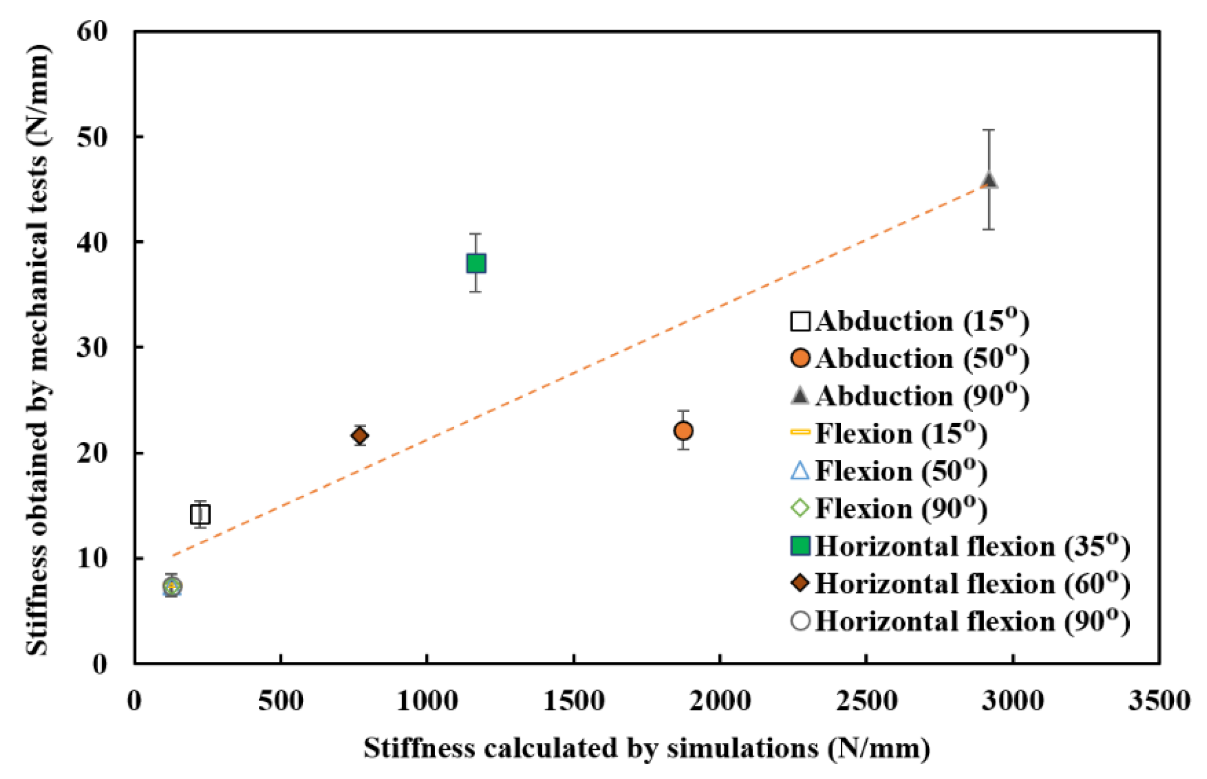
3.2. Mechanical Testing Outcomes

The stiffness results of finite element models were analyzed and validated using biomechanical experiments. The stiffness of plate bone constructs was calculated from the linear portion of the load displacement curve. In the static load case, the stiffness of the plate bone construct was 14.2 N/mm at the 15° position and 22.2 N/mm and 45.9 N/mm at both the 50° and 90° positions for abduction motion, respectively. Stiffness was relatively high when the loading direction was approximately along the humeral axis, but relatively low when it was perpendicular to it significantly (p < 0.05). In horizontal flexion motion, the construct had a stiffness of 38 N/mm at 35° position and reduced to 21.6 N/mm and 7.4 N/mm at 60° and 90° positions respectively. Loading approximately along the humeral axis produced relatively small stiffness, but loading perpendicular to it produced relatively high stiffness significantly (p < 0.05). The stiffness was 7.4 N/mm for all the positions of flexion movements and was lower significantly (p < 0.05) than those of abduction and horizontal flexion motion. The mechanical test results under different motions were closely correlated with computer numerical simulation results with a high correlation coefficient of 0.88 (Figure 6).

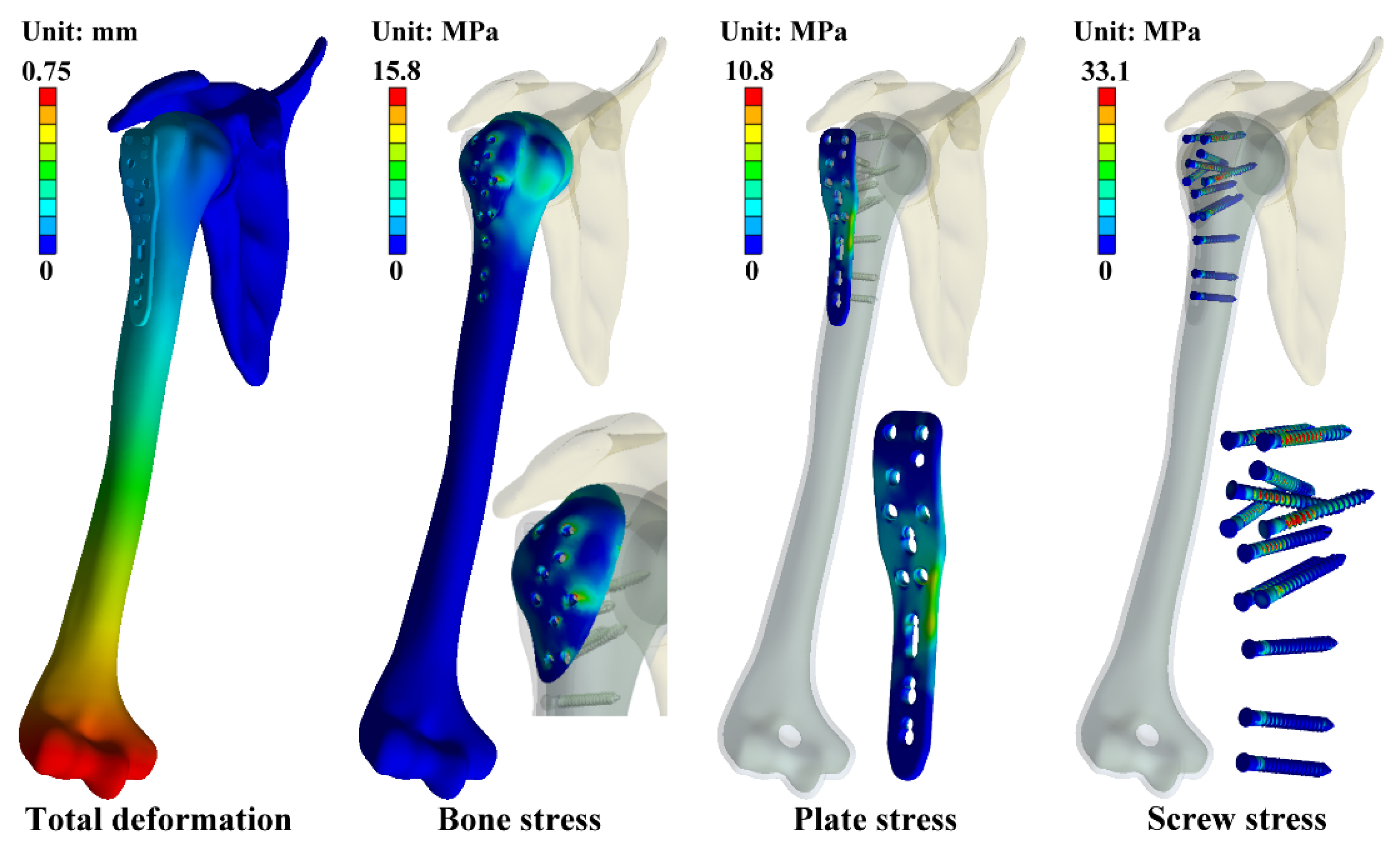
3.3. Finite Element Simulation under the Realistic Rotator Cuff Muscle Loading

The realistic muscle force was applied to the validated finite element shoulder joint model to calculate the displacement at the fracture site, bone stress, plate stress, and mean screw stress for various positions of the three shoulder motions (Table 1, Figure 7). The maximum deformation was found at the humerus distal end. The displacement at the fracture site was maximum at 90° abduction position, 65° flexion position, and 50 and 70° horizontal flexion positions in the corresponding motions. Overall, the horizontal flexion movements had relatively larger displacements than the flexion and abduction movements. The maximum stress in the plate, screw, and bone that appeared at the locking screw holes of the plate, screws around the fracture site, and at the humeral head of the bone around the screw hole were much lower than the yield strength of the implant and bone for all configurations of the models. For all positions of the abduction and flexion motions, the maximum stresses in the plate, screw, and bone for the GT fracture model did not significantly change; however, the maximum stress for the horizontal flexion motion varied significantly. When compared to flexion and abduction movements, horizontal flexion movements had relatively larger maximum stresses in the plate, screw, and bone.

4. Discussion

Displaced GT fractures, considered as being uncommon, have remained less well understood. In a young population, these fractures occur with standard bone quality as a result of high-energy trauma. Also, most of these types of fractures are caused by impaction of the GT onto the anterior surface of the glenoid or traction force generated by the rotator cuff muscle. Various treatment options were used earlier, but no optimal fixation methods are reported in the literature. Surgical techniques to fix displaced GT fractures have been used, including suture fixation, tension band wire, percutaneous screw fixation, and plate fixation. Gillespie et al. studied the GT fracture treatment for 11 treatment cases with locking compression plates and showed the results that the fractures had achieved union in all cases, and the patient’s shoulder range of motion was not affected [4]. The report by Park et al. demonstrated a more accurate restoration of fractured fragments using an arthroscopic-assisted bone plate for the treatment of displaced large-sized comminuted GT fractures in 11 patients [6]. Bogdan et al. reported on 8 months of outcomes of internal fixation using a mesh plate in GT fractures in nine patients in whom the fracture has healed with no problem of malunion and implant damage [3]. Ma et al. evaluated the F3 Biomet plate fixation in GT fractures of 11 patients and found good results in fracture healing in all the cases [5]. The present study resulted in similar findings and supported that the displaced GT fracture could be successfully fixed with locking plates. Despite its common usage, locking plate fixation for GT fracture is associated with some limitations and disadvantages in clinical application [3,5,6,7].
To our knowledge, only a few biomechanical studies has been investigated in GT-fracture-treated shoulders involving rotator cuff muscles that affect rehabilitation activities [11,12,27]. Mihata et al. found greater biomechanical effects at a high shoulder abduction position for the conventional double-row technique and at low abduction angles for the bridging sutures technique in their studies [12]. Lin et al. resulted that the fixation techniques of double row suture anchor and suture bridge had superior initial fixation strengths at a low and high abduction angles, respectively, whereas the screw fixation technique was unaffected in their humeral GT fracture treatment study [27]. However, these studies were limited to only abduction movements for various angles of the humerus in their analyses. After surgery, the biomechanical properties of the repaired GT fragment were influenced by shoulder positions and activities, because the load on the GT fragment varies with shoulder positions and activities. Thus, the present study considered three types of shoulder rehabilitation activities including abduction, flexion, and horizontal flexion for various positions [26].
Optimizing the shoulder rehabilitation exercises is necessary to avoid the failure of GT fracture fixation after surgery. With rehabilitation exercises after a GT fracture treatment using locking plates, the shoulder functions can be regained in the shortest possible time. Therefore, activity must be started at the earliest after fracture fixation. During the early stages after fracture treatment, maintaining the controlled stresses throughout the fracture site will optimize fracture healing without increasing complications. The current research sought to explore the biomechanical results of the bone plate treatment strategy for shoulder joint rehabilitation of a GT fracture. Based on clinical trials, it is difficult to analyze the biomechanical behaviors of the repaired shoulder joint. Also, studying mechanically the behavior of cadaveric specimens for rehabilitation activities can be challenging due to bone anatomy variations, bone density, and bone fracture pattern. These problems could be solved using a numerical approach. The numerical model used in this research for biomechanical analysis, with realistic muscle forces, was well-validated with experimental tests with a single traction force condition. The results showed that the stiffness of the construct was increased significantly at high abduction angles and low horizontal flexion angles, and not changed for any positions of the flexion movements. Of the three shoulder rehabilitation exercises investigated, horizontal flexion displayed the most unfavorable characteristics. The null hypothesis was rejected, since rehabilitation activities showed different biomechanical behavior in the shoulder joint with GT fracture fixation with locking plates. The displacements at the fracture site, as well as bone stress, bone plate stress, and average bone screw stress were higher in horizontal flexion than abduction and flexion movements. These results suggested that GT-fracture-treated shoulders using the locking plate technique should be not or minimally mobilized with horizontal flexion during rehabilitation activities, since it may increase the possibility of implant failure and bone breakage at the early stage. Therefore, horizontal flexion activities may be recommended in the later stage of shoulder joint rehabilitation with high caution.
An artificial humerus with a more consistent geometry and material properties to the human humerus was selected as the testing material. Researchers found more realistic experimental outcomes with cadaveric humerus fracture models in their studies. Cadaveric bone models, however, may not be the best choice as they may show variations in bone anatomy, bone density, or fracture patterns [19,21]. These variations may surpass the biomechanical effects when experimenting the shoulder rehabilitation activities at different positions. Also, availability of cadaveric humeri is sometimes limited and difficult to obtain [20]. In the present study, artificial humeri were used because of the above-noted problems with cadaveric humerus.
There are some limitations in this study. Firstly, linear elastic isotropic material properties were assumed for the GT fractured shoulder joint models in this study. The numerical analysis produced only the relative outcomes for all situations. Secondly, the loading of shoulder joint construct was simplified to mimic only the supraspinatus, infraspinatus, and subscapularis muscle load. The shoulder is generally controlled by a more complex combination of dynamic and static stabilizers that our experimental model does not consider. Thirdly, motion in the current model was limited to along the longitudinal axis of the bone. Although it was sufficient for in vitro results, other motions such as internal and external rotation may result in more accurate biomechanical analysis that warrant further study. Finally, this study considered only two-part greater tuberosity fracture for the biomechanical investigation of locking plate systems for proximal humerus fracture fixations during shoulder rehabilitation activities using rotator cuff muscle forces. Other humerus fracture models also need to be considered in future research, such as the three-part nondisplaced proximal humerus fracture, three-part displaced proximal humerus fracture, and four-part humerus fracture.

5. Conclusions

Both numerical and experimental approaches indicated that the stiffness of the construct increased significantly at high abduction angles and low horizontal flexion angles, and was not changed for any positions of the flexion movements. The shoulder joint had a larger displacement at the fracture site, a higher plate stress, higher mean screw stress, and higher bone stress with a horizontal flexion compared to that with abduction and flexion activities. Under realistic rotator cuff muscle loading, the GT fracture treated with locking plate fixation had higher bone fragment deformation at horizontal flexion motions, especially at 50 and 70°. Therefore, horizontal flexion activities may be suggested in the later stage of shoulder joint rehabilitation with high cautiousness. These methodologies could be used to evaluate new implant designs and fixation strategies for shoulder joints.

Author Contributions

Conceptualization, C.-K.C. and C.-C.H.; Formal analysis, B.M., C.-C.H. and M.-H.L.; Funding acquisition, C.-C.H.; Investigation, B.M., C.-K.C., C.-C.H. and M.-H.L.; Methodology, B.M., C.-K.C., C.-C.H. and M.-H.L.; Resources, C.-K.C. and C.-C.H.; Validation, B.M., C.-K.C. and C.-C.H.; Writing—original draft, B.M., C.-C.H. and M.-H.L.; Writing—review & editing, B.M., C.-K.C. and C.-C.H. All authors have read and agreed to the published version of the manuscript.

Funding

This research was funded by Ministry of Science and Technology, Taiwan, grant number MOST 109-2221-E-011-035.

Institutional Review Board Statement

Not applicable.

Informed Consent Statement

Not applicable. This study did not involve humans or animals.

Data Availability Statement

The data presented in this study are available on request from the corresponding author.

Conflicts of Interest

The authors declare no conflict of interest.

References

  1. Gruson, K.I.; Ruchelsman, D.E.; Tejwani, N. Isolated tuberosity fractures of the proximal humerus: Current concepts. Injury 2008, 39, 284–298. [Google Scholar] [CrossRef] [PubMed]
  2. Mutch, J.; Laflamme, G.Y.; Hagemeister, N.; Cikes, A.; Rouleau, D.M. A new morphological classification for greater tuberosity fractures of the proximal humerus: Validation and clinical implications. Bone Jt. J. 2014, 96-B, 646–651. [Google Scholar] [CrossRef] [PubMed] [Green Version]
  3. Bogdan, Y.; Gausden, E.B.; Zbeda, R.; Helfet, D.L.; Lorich, D.G.; Wellman, D.S. An alternative technique for greater tuberosity fractures: Use of the mesh plate. Arch. Orthop. Trauma. Surg. 2017, 137, 1067–1070. [Google Scholar] [CrossRef] [PubMed]
  4. Gillespie, R.J.; Johnston, P.S.; Gordon, V.A.; Ward, P.J.; Getz, C.L. Using Plate Osteosynthesis to Treat Isolated Greater Tuberosity Fractures. Am. J. Orthop. 2015, 44, E248–E251. [Google Scholar]
  5. Ma, J.; Zhao, L.; Liu, T.; Fu, Q.; Chen, A. A Retrospective Study in the Treatment of a 2-Part Greater Tuberosity Fracture Using the F3 Biomet Plate. Int. Surg. 2016, 101, 465–472. [Google Scholar] [CrossRef] [Green Version]
  6. Park, S.-E.; Jeong, J.-J.; Panchal, K.; Lee, J.-Y.; Min, H.-K.; Ji, J.-H. Arthroscopic-assisted plate fixation for displaced large-sized comminuted greater tuberosity fractures of proximal humerus: A novel surgical technique. Knee Surg. Sports Traumatol. Arthrosc. 2016, 24, 3892–3898. [Google Scholar] [CrossRef]
  7. Ji, J.-H.; Shafi, M.; Song, I.-S.; Kim, Y.-Y.; McFarland, E.G.; Moon, C.-Y. Arthroscopic Fixation Technique for Comminuted, Displaced Greater Tuberosity Fracture. Arthrosc. J. Arthrosc. Relat. Surg. 2010, 26, 600–609. [Google Scholar] [CrossRef]
  8. Brais, G.; Ménard, J.; Mutch, J.; Laflamme, G.-Y.; Petit, Y.; Rouleau, D.M. Transosseous braided-tape and double-row fixations are better than tension band for avulsion-type greater tuberosity fractures. Injury 2015, 46, 1007–1012. [Google Scholar] [CrossRef]
  9. Gaudelli, C.; Ménard, J.; Mutch, J.; Laflamme, G.-Y.; Petit, Y.; Rouleau, D.M. Locking plate fixation provides superior fixation of humerus split type greater tuberosity fractures than tension bands and double row suture bridges. Clin. Biomech. 2014, 29, 1003–1008. [Google Scholar] [CrossRef]
  10. Knierzinger, D.; Heinrichs, C.H.; Hengg, C.; Konschake, M.; Kralinger, F.; Schmoelz, W. Biomechanical evaluation of cable and suture cerclages for tuberosity reattachment in a 4-part proximal humeral fracture model treated with reverse shoulder arthroplasty. J. Shoulder Elb. Surg. 2018, 27, 1816–1823. [Google Scholar] [CrossRef]
  11. Lin, C.-L.; Yeh, M.-L.; Su, F.-C.; Wang, Y.-C.; Chiang, C.H.; Hong, C.-K.; Su, W.-R. Different suture anchor fixation techniques affect contact properties in humeral greater tuberosity fracture: A biomechanical study. BMC Musculoskelet. Disord. 2019, 20, 26. [Google Scholar] [CrossRef]
  12. Mihata, T.; Fukuhara, T.; Jun, B.J.; Watanabe, C.; Kinoshita, M. Effect of Shoulder Abduction Angle on Biomechanical Properties of the Repaired Rotator Cuff Tendons With 3 Types of Double-Row Technique. Am. J. Sports Med. 2010, 39, 551–556. [Google Scholar] [CrossRef] [PubMed]
  13. Palumbo, B.T.; Gutierrez, S.; Santoni, B.; Mighell, M. Biomechanical Investigation of Locked Plate Fixation with Suture Augmentation in a Comminuted Three-Part Proximal Humerus Fracture Model. Open J. Orthop. 2017, 7, 180–191. [Google Scholar] [CrossRef] [Green Version]
  14. St-Jean, B.L.; Ménard, J.; Hinse, S.; Petit, Y.; Rouleau, D.M.; Beauchamp, M. Braided tape suture provides superior bone pull-through strength than wire suture in greater tuberosity of the humerus. J. Orthop. 2015, 12, S14–S17. [Google Scholar] [CrossRef] [PubMed] [Green Version]
  15. Feerick, E.M.; Kennedy, J.; Mullett, H.; FitzPatrick, D.; McGarry, P. Investigation of metallic and carbon fibre PEEK fracture fixation devices for three-part proximal humeral fractures. Med. Eng. Phys. 2013, 35, 712–722. [Google Scholar] [CrossRef]
  16. Fletcher, J.W.A.; Windolf, M.; Richards, R.G.; Gueorguiev, B.; Buschbaum, J.; Varga, P. Importance of locking plate positioning in proximal humeral fractures as predicted by computer simulations. J. Orthop. Res. 2019, 37, 957–964. [Google Scholar] [CrossRef]
  17. Shen, L.; Zhang, W.; Wang, Q.; Chen, Y. Establishment of a three-dimensional finite element model and biomechanical analysis of three different internal fixation methods for humeral greater tuberosity fracture. Int. J. Clin. Exp. Med. 2018, 11, 3245–3254. [Google Scholar]
  18. Varga, P.; Inzana, J.A.; Gueorguiev, B.; Südkamp, N.P.; Windolf, M. Validated computational framework for efficient systematic evaluation of osteoporotic fracture fixation in the proximal humerus. Med. Eng. Phys. 2018, 57, 29–39. [Google Scholar] [CrossRef]
  19. Burke, N.G.; Kennedy, J.; Cousins, G.; FitzPatrick, D.; Mullett, H. Locking Plate Fixation with and without Inferomedial Screws for Proximal Humeral Fractures: A Biomechanical Study. J. Orthop. Surg. 2014, 22, 190–194. [Google Scholar] [CrossRef] [Green Version]
  20. Lee, C.-H.; Hsu, C.-C.; Huang, P.-Y. Biomechanical study of different fixation techniques for the treatment of sacroiliac joint injuries using finite element analyses and biomechanical tests. Comput. Biol. Med. 2017, 87, 250–257. [Google Scholar] [CrossRef]
  21. Osterhoff, G.; Baumgartner, D.; Favre, P.; Wanner, G.A.; Gerber, H.; Simmen, H.-P.; Werner, C.M. Medial support by fibula bone graft in angular stable plate fixation of proximal humeral fractures: An in vitro study with synthetic bone. J. Shoulder Elb. Surg. 2011, 20, 740–746. [Google Scholar] [CrossRef] [PubMed]
  22. Ausiello, P.; Ciaramella, S.; Di Rienzo, A.; Lanzotti, A.; Ventre, M.; Watts, D.C. Adhesive class I restorations in sound molar teeth incorporating combined resin-composite and glass ionomer materials: CAD-FE modeling and analysis. Dent. Mater. 2019, 35, 1514–1522. [Google Scholar] [CrossRef] [PubMed]
  23. Campaner, L.M.; Silveira, M.P.M.; de Andrade, G.S.; Borges, A.L.S.; Bottino, M.A.; de OliveiraDal Piva, A.M.; Lo Giudice, R.; Ausiello, P.; Tribst, J.P.M. Influence of polymeric restorative materials on the stress distribution in posterior fixed partial dentures: 3D finite element analysis. Polymers 2021, 13, 758. [Google Scholar] [CrossRef] [PubMed]
  24. Parizi, F.S.; Mehrabi, R.; Karamooz-Ravari, M.R. Finite element analysis of NiTi self-expandable heart valve stent. Proc. Inst. Mech. Eng. Part H J. Eng. Med. 2019, 233, 1042–1050. [Google Scholar] [CrossRef]
  25. Ye, Y.; You, W.; Zhu, W.; Cui, J.; Chen, K.; Wang, D. The Applications of Finite Element Analysis in Proximal Humeral Fractures. Comput. Math. Methods Med. 2017, 2017, 4879836. [Google Scholar] [CrossRef]
  26. Wu, W.; Lee, P.V.; Bryant, A.L.; Galea, M.; Ackland, D.C. Subject-specific musculoskeletal modeling in the evaluation of shoulder muscle and joint function. J. Biomech. 2016, 49, 3626–3634. [Google Scholar] [CrossRef]
  27. Lin, C.-L.; Su, F.-C.; Chang, C.-H.; Hong, C.-K.; Jou, I.-M.; Lin, C.-J.; Su, W.-R. Effect of shoulder abduction on the fixation of humeral greater tuberosity fractures: A biomechanical study for three types of fixation constructs. J. Shoulder Elb. Surg. 2015, 24, 547–554. [Google Scholar] [CrossRef]
  28. Curtis, A.S.; Burbank, K.M.; Tierney, J.J.; Scheller, A.D.; Curran, A.R. The Insertional Footprint of the Rotator Cuff: An Anatomic Study. Arthrosc. J. Arthrosc. Relat. Surg. 2006, 22, 603–609. [Google Scholar] [CrossRef]
Figure 1. Definition of shoulder joint rehabilitation activities.
Applsci 12 06802 g001
Figure 2. Finite element models under mechanical testing loading.
Applsci 12 06802 g002
Figure 3. Mechanical test setups for different humerus motions.
Applsci 12 06802 g003
Figure 4. Finite element models under realistic rotator cuff muscle loading.
Applsci 12 06802 g004
Figure 5. Total deformation of humerus under mechanical testing loading.
Applsci 12 06802 g005
Figure 6. Correlation study between the mechanical tests and the finite element analysis.
Applsci 12 06802 g006
Figure 7. The deformation and stress distributions of the finite element models under the shoulder joint activity position of 15° for abduction.
Applsci 12 06802 g007
Table 1. The results of the finite element models under realistic muscle loading.
Rehabilitation MovementPosition (°)Displacement at Fracture Site (mm)Max. Bone Stress (MPa)Max. Plate Stress (MPa)Mean Screw Stress (MPa)
Abduction150.14415.810.815.6
400.13323.813.124.4
650.07522.212.122.0
900.20817.17.613.7
Flexion150.15519.612.717.5
400.33825.114.123.5
650.57323.417.821.3
900.45031.518.621.7
Horizontal flexion350.49140.514.812.6
501.02260.629.137.3
701.16356.129.034.0
900.48633.016.421.2
Publisher’s Note: MDPI stays neutral with regard to jurisdictional claims in published maps and institutional affiliations.

