Abstract
This work is focused on the application of a laser-based technique, i.e., matrix-assisted pulsed laser evaporation (MAPLE) for the development of electrochemical sensors aimed at the detection of nitrites in water. Commercial carbon-based screen-printed electrodes were modified by MAPLE via the application of a newly developed composite coating with different concentrations of carbon nanotubes (CNTs), chitosan, and iron (II) phthalocyanine (C32H16FeN8). The performance of the newly fabricated composite coatings was evaluated both by investigating the morphology and surface chemistry of the coating, and by determining the electro-catalytic oxidation properties of nitrite with bare and modified commercial carbon-based screen-printed electrode. It was found that the combined effect of CNTs with chitosan and C32H16FeN8 significantly improves the electrochemical response towards the oxidation of nitrite. In addition, the MAPLE modified screen-printed electrodes have a limit of detection of 0.12 µM, which make them extremely useful for the detection of nitrite traces.
1. Introduction
Nitrites (compounds that contain the nitrite ion NO2−) are widely studied for their applications in food and chemical industries, but also for their potential toxicity. In particular, the detection of nitrites is important due to their potential to affect human health leading to liver damage, methemoglobinemia, and even cancers [1]. In addition, nitrites cause methemoglobinemia by oxidizing the Fe2+ of haemoglobin [2]. Furthermore, according to the World Health Organization, the nitrate concentration in drinkable water should not exceed 65.2 µM (3 ppm) [3].
In order to monitor the presence of nitrites in water, food, and environmental systems, many detection methods are designed. Colorimetry and spectrophotometry are some early detection techniques, but these methods have low accuracy and are easily affected by other substances. A technique with better precision but with high cost and poor portability is gas/liquid chromatography-mass spectrometry [4]
Therefore, in recent years, electrochemical sensors have been intensely used as an alternative for detecting nitrites in water, due to their low cost and high portability. The primary mechanism for detection is based on the electro-oxidation of nitrite ions, which produces a modification in the signal recorded by the sensor. Generally, the oxidation rate depends on the electron transfer kinetics and electro-active ability of the electrode. The most common materials used for the fabrication of electrodes are platinum, gold, copper, silver, carbon, and glassy carbon. The central performances desired from an electrochemical sensor are the linearity of the sensor’s output with the recorded signal, a low limit of detection (LOD), high selectivity for a specific contaminant, and high sensitivity. The modification of the electrode with carbon nanomaterials, such as carbon nanotubes (CNTs), metallic nanoparticles (NPs), macromolecules, and polymers, can improve the detection performances of the electrochemical sensors [4,5,6,7].
Few examples electrochemical sensors based on carbon nanotubes doped or decorated with different nanoparticles are reported in [8,9,10,11]. The authors use the sensors for the detection of nitrites and they report LOD between 0.001 and 0.5 µM.
An interesting organic material studied for biosensors is chitosan, which is generally combined with metal-oxide nanoparticles or carbon nanotubes to increase its electrical properties for sensing applications [12,13]. Bibi et al. [14] presented an MWCNT paste electrode modified with chitosan functionalized Ag-NPs while Li et al. [15] reported a sensor based on chitosan, MWCNTs, and carbon nanoparticles (CNs), and Bai et al. presented a multilayer film sensor based on H7P2Mo17V1O62 (P2Mo17V)-carbon nanotubes and Pt-chitosan [16].
A novel highly sensitive electrochemical sensor is reported by Wang et al. [17]. A Chit/Ti3C3 solution was deposited on glassy carbon electrodes, and the obtained electrode is immersed in a phosphate buffer solution containing HAuCl4 and reduced by cyclic voltammetry in order to deposit gold nanoparticles. The resulted electrode AuNPs/Chit/Ti3C2Tx/GCE showed good performance, two linear ranges, 0.5–335 μM and 335–3355 μM, and LOD of 0.069 μM. In their previous research [18], a AuNPs/Ti3C2Tx/ERGO/GCE sensor was designed exhibiting linear ranges 0.5–80 μM and 80–780 μM with limits of detection 0.15 μM and 0.051 μM for nitrites sensing.
Furthermore, biological compounds are studied for sensor applications. For instance, a high-performance electrochemical sensor based on SWCNTs covalently immobilized with single-strand deoxyribonucleic acid (SWCNTs-ssDNA) for the detection of nitrite is presented by Xian et al. [19], while in Yang et al. [20], DNA functionalized single-wall carbon nanotubes/Cu2+ (DNA–CNTs/Cu2+) are shown. The Cu2+ modified SWCNTs-ssDNA sensor exhibited lower LOD and a more extensive linear range.
Thus, in this work we aim at the application of a laser-based deposition approach, i.e., matrix-assisted pulsed laser evaporation (MAPLE) [21,22,23] for the development of an electrochemical sensor. Briefly, the MAPLE process is similar to the conventional pulsed laser deposition (PLD) method which involves the interaction of a laser beam with a solid target inside of a vacuum chamber and the formation of a plasma plume which condenses onto a substrate to form a thin film. The main difference between the two techniques is the solid target, i.e., in MAPLE, the sensitive material is suspended in a solvent at low concentrations (also called matrix) and flash frozen in liquid nitrogen. The most important advantage of MAPLE is its high flexibility, allowing most of the materials which can be dissolved or suspended in a highly volatile and light-absorbing solvent to be deposited as a thin film [22,23]. Other advantages are related to: (i) a better control of the film thickness and surface morphology, (ii) an enhanced film/substrate adhesion, (iii) the usage of low quantities of material, and (iv) it is compatible with low laser fluences.
In this work, an electrochemical sensor based on a carbon nanotube (CNTs), chitosan, and iron (II) phtalocyanine (C32H16FeN8) (abbreviated CNT-Chit-FePc) composite is reported. The CNT-Chit-FePc composite is applied as a thin film by matrix-assisted pulsed laser evaporation (MAPLE) onto the surface of commercially available carbon-based screen-printed electrodes (C-SPE). The novelty and advantage of this work arises from the possibility to apply a facile one-step strategy, i.e., MAPLE, to obtain hybrid coatings with promising performance in nitrite sensing. In addition, the laser-processed C-SPEs exhibit satisfactory selectivity and stability, demonstrating its capability and promise in trace nitrite determination in water. The carbon-screen printed electrode modified by MAPLE with a CNT-Chit-FePc composite, by virtue of its simplicity, ease of fabrication and use, could be extended for detection of nitrites in the human body. For example, C32H16FeN8 has a similar structure to haemoglobin [24], and thus Fe3+ reduces NO2− ions [25].
2. Materials and Methods
2.1. Laser Processing of the Sensing Materials for the Working Electrode
The electrochemical sensor sensitive layer was based on a composite containing CNT (carbon nanotube, single-walled, solvent-based conductive ink from Merck KGaA, Darmstadt, Germany), chitosan (natural polymer from Merck KGaA, Darmstadt, Germany), and iron (II) phthalocyanine (from Merck KGaA, Darmstadt, Germany) with improved physical and chemical properties, due to their complementary behaviour that is not possible from their single counterparts.
The sensitive layer was applied on the working electrode of a commercial carbon-based screen-printed electrode (C-SPE) (from Dropsense, Asturias, Spain) by means of matrix-assisted pulsed laser evaporation (MAPLE) (commercial system from Neocera LLC, Beltsville, MD, USA). A sketch of the MAPLE experimental setup used in this work is shown in Figure 1.
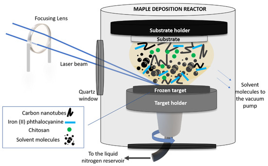
Figure 1.
Sketch of the MAPLE setup used in this work.
In order to carry out the MAPLE experiments, we first fabricated the solid targets which were irradiated by the laser beam. In this work, the CNT-Chit-FePc mixture was suspended in water (at different concentrations, see Table 1) and flash frozen using liquid nitrogen, resulting a solid target. The choice of the different concentrations used in this work was based on our preliminary study reported in [26], where we proved the possibility to process new composites based on (CNT (2%), chitosan (0.5%), and C32H16FeN8 (0.4%) without structural modifications. Chitosan was used as a matrix for the entrapment of the composite based on CNT and C32H16FeN8 and allowed for a uniform and controllable distribution of the compounds in the coating. Moreover, it was also found that the impact of FePc loading becomes saturated for high loadings (i.e., from 50 to 100 mg) [27].

Table 1.
Composition of the targets used for the MAPLE experiments.
The frozen solid target was then inserted into the vacuum chamber (working pressure of 5 × 10⁻⁵ mbar) and irradiated with a pulsed Nd:YAG laser beam (Surelite II from Continuum, Bordeaux, France) (λ = 266 nm, ν = 10 Hz and τ = 5–7 ns). The laser beam was guided and focused through an optical system (mirrors and lens) in the processing chamber, at an angle of incidence of ~45° on the surface of the solid target. The laser fluence was set at 580 mJ/cm2.
Upon irradiation, the solvent evaporated and was pumped out of the deposition chamber, allowing only for the composite material to be collected as a thin film on a substrate placed parallel to the target at a distance of approximately 4 cm. The target was rotated by a motor and at the same time the laser beam was scanned onto the surface of the target to achieve a uniform evaporation. The substrates used to collect the thin film materials were Si(100) (used for post-deposition morphological and chemical investigations) and C110 sensors from Metrohm Dropsens, Asturias, Spain (C-SPE). The thickness of the as-deposited layers was approx. 80 nm (please see Figure S1).
2.2. Characterization of the Sensing Coatings Processed by MAPLE
The morphological features of the laser processed sensing layers were investigated by FEI Inspect-S scanning electron microscope (Thermo Fisher Scientific Inc., Waltham, MA, USA) at an accelerating voltage between 5–20 kV.
Fourier-transform infra-red (FTIR) spectroscopy was used to obtain the infra-red (IR) absorption spectra of the as-deposited coatings. The IR spectra of the coatings were recorded as a mean of 16 spectra with a Nicolet FT-IR iS50 spectrometer (Thermo Fisher Scientific, Waltham, MA, USA) equipped with an attenuated total reflection (ATR) module. The resolution was 4 cm−1 and the spectral range 4000–650 cm−1. FTIR-ATR measurements were carried out using a ZnSe crystal with the following properties: 1.5 mm diameter, one internal reflection at a 42° angle of incidence, and 2.03 µm depth of penetration at 1000 cm−1.
The surface wettability of the sensing layers was measured by using the sessile drop method applied at constant temperature of 20 °C. A droplet (4 μL) was placed on the surface of the as-deposited coatings and the contact angle measurements were performed using a KSVCAM101 microscope (KSV Instruments Ltd., Espoo, Finland) equipped with a video-camera and FireWire interface, which allowed the acquisition of images with a resolution of 640 × 480 pixels. The surface free energy (SFE) was calculated using two wet agents: deionized water as a polar liquid, and for the completely dispersive liquid, di-iodomethane. The final SFE values were extracted from contact angle measurements and conducted using the concept of polar and dispersion components by means of the Owens, Wendt, Rabel, and Kaelble (OWRK) method for estimation [28,29,30].
For the electrochemical investigation of the sensors based on CNT-Chit-FePc, all chemicals were analytical grade and used with no further purification. Sodium nitrite (NaNO2—Merck KGaA, Darmstadt, Germany, purity ≥ 99.0%) was used for the preparation of solutions containing nitrite ions. The standard Briton Robinson (BR) buffer was prepared by using acetic acid (CH3COOH—Sigma-Aldrich, purity ≥ 99%), boric acid (H3BO3—Sigma-Aldrich, purity ≥ 99.5%), and phosphoric acid (H3PO3—Merck KGaA, Darmstadt, Germany). The electrochemical measurements were performed using an AutoLab PGSTAT302N (Utrecht, The Netherlands) controlled by NOVA 1.11 software (Utrecht, The Netherlands). Detection of nitrite was studied using both voltammetric and amperometric techniques. All samples were tested in a 10 mL electrochemical reactor, filled before each measurement with fresh solution of 0.1 M BR electrolyte. During the voltammetric investigation of sensors, the potential was varied from 0.1 V to 1.2 V (vs. Ag/AgCl), and vice versa. The pH value of the supporting electrolyte was adjusted between 3 and 7 and its influence on the electrochemical process was rigorously studied. Nitrite oxidation was amperometrically studied at an applied potential of 0.8 V vs. Ag/AgCl in the same electrochemical cell. Nitrite content was added step-by-step to the electrolyte solution using the standard addition method.
3. Results and Discussions
3.1. Surface Chemistry Investigations: FTIR, Contact Angle, and Surface Free Measurements
The successful laser deposition of the composite coating, i.e., CNT-Chit-FePc, and the investigation of the surface functional groups was evaluated by Fourier transformed infra-red (FTIR) spectroscopy.
First, the IR spectra of the starting materials, i.e., chitosan, C32H16FeN8, and CNTs pre-processed by MAPLE, were investigated. The acquired spectra of the starting materials, shown in Figure S2a–c, are similar to those reported in [31,32,33,34,35,36].
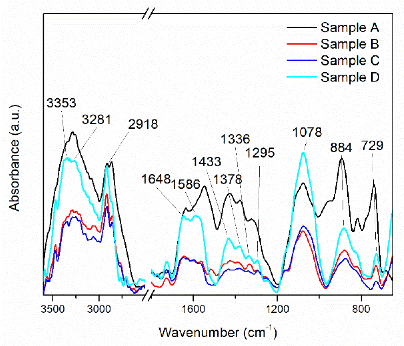
In the FTIR spectra of the MAPLE-deposited CNT-Chit-FePc composites (shown in Figure 2), chitosan is identified by the bands at 1648 cm−1 (C=O stretching vibration of amide I), 1586 cm−1 (N–H bending vibration of amide II), 1378 cm−1 (C–H symmetrical deformation vibrations of CH3), 1078 cm−1 (C–O stretching vibration), and 884 cm−1 (C–H bending out of the plane of the ring of monosaccharides). Some of the bands are shifted when compared with the bands of individual chitosan. C32H16FeN8 is recognized in the thin films at 1336 cm−1 (C–N stretching vibration) and 729 cm−1 (C–N bending vibration), whereas CNT at 1245 cm−1 and 1295 cm−1 (C–H bending vibrations and combinations of OH deformation and of C–O stretching vibrations).
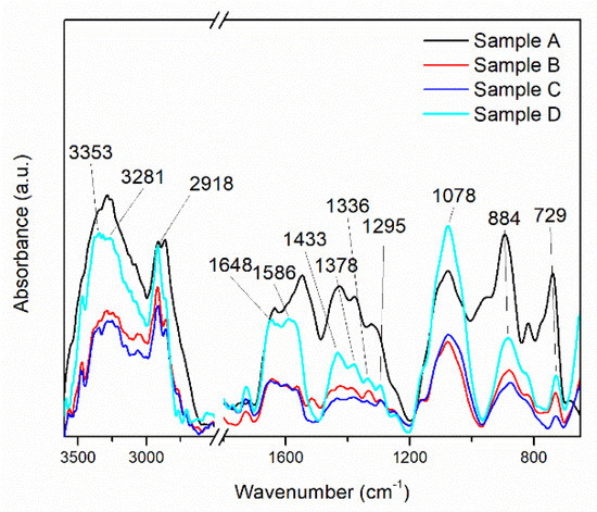
Figure 2.
This FT−IR spectra of the MAPLE deposited CNT-Chit-FePc composite from different targets: Sample A (target containing (15% CNT + 1% Chit + 1% C32H16FeN8) in H2O); Sample B (target containing (15% CNT + 1% Chit + 0.4% C32H16FeN8) in H2O); Sample C (target containing (22% CNT + 1% Chit + 0.4% C32H16FeN8) in H2O); Sample D (target containing (22% CNT + 1% Chit + 1% C32H16FeN8) in H2O).
Despite CNT having the highest ration content of all the materials, the existence of only two bands in the CNT-Chit-FePc composite IR spectrum is due to CNT’s weak dynamic dipole moment when compared with that of chitosan and C32H16FeN8 [35]. The disappearance from the CNT-Chit-FePc composite IR spectrum of the CNT bands at 1609, 1510, 1453, 1362, 1348, 1185, and 1103 cm−1 indicates that the functional groups on the surface of the CNT were consumed or neutralized during the composite formation process. Furthermore, electrostatic interaction between chitosan and CNT could explain the shifted bands observed for chitosan in the CNT-Chit-FePc composite IR spectrum when compared to individual chitosan [35]. The successful deposition of the starting materials as thin films without affecting their structural damage can be confirmed by the presence of their characteristic IR bands without any significant changes in peak positions in the CNT-Chit-FePc composite IR spectrum.
The successful deposition of the starting materials as thin films without affecting their structural damage can be confirmed by the presence of their characteristic IR bands without any significant changes in peak positions in the CNT-Chit-FePc composite IR spectrum. Therefore, MAPLE is eligible for composite transfer from the frozen matrix to the collector as a thin layer without noticeable chemical/structural damages.
Contact-angle measurements were used on a large scale for the characterization of thin film surface wettability, and the results are presented in Figure 3.

Figure 3.
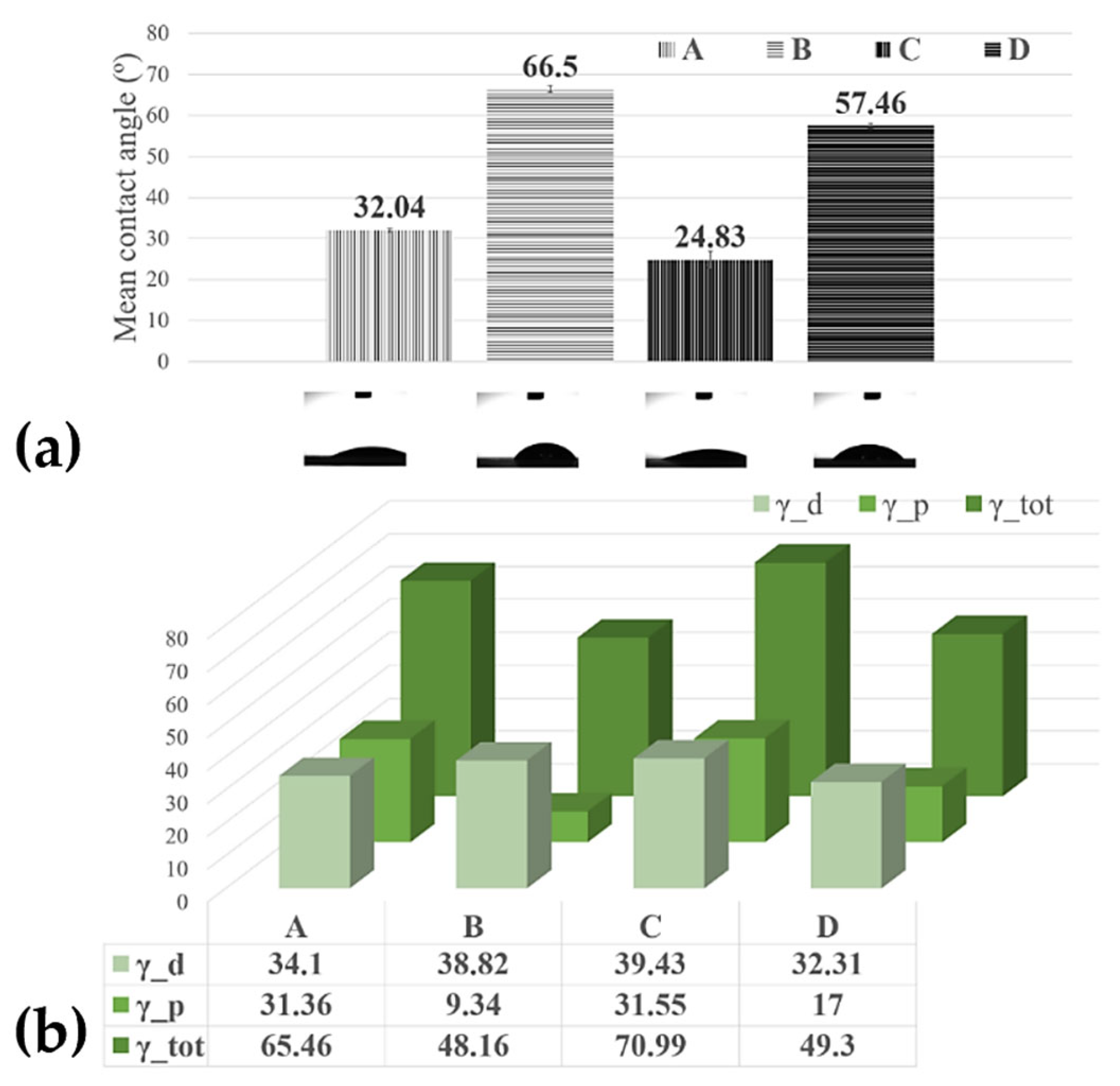
(a) Histograms of the contact angles measured on the MAPLE processed surfaces; (b) surface free energy of the MAPLE processed surfaces from targets with the different compositions: Sample A (target containing (15% CNT + 1% Chit + 1% C32H16FeN8) in H2O); Sample B (target containing (15% CNT + 1% Chit + 0.4% C32H16FeN8) in H2O); Sample C (target containing (22% CNT + 1% Chit + 0.4% C32H16FeN8) in H2O); Sample D (target containing (22% CNT + 1% Chit + 1% C32H16FeN8) in H2O).
The contact angle of water at the surface of the bare C-SPE was measured, and the value was ~73°. However, it decreased after the C-SPE was coated with CNT-Chit-FePc. This increase in the hydrophilicity of the coated electrode indicates that the properties of the CNT-Chit-FePc composite can be tuned using a laser evaporation technique. In the study reported in [37] it was found that the ammonia group in the chitosan molecular chain has a strong affinity to the CNT surface, thus potentially explaining the higher contact angles of the sample D (57.46°) compared with sample A (32.04°), and sample B (66.5°) compared with the sample C (24.83°), respectively. Some theoretical calculations prove the helical wrapping on CNTs is the optimal configuration for polymers of rigid molecular chains [38,39]. The biopolymer chitosan is helically wrapped on the CNT surface, favouring CNT solubilization in water. A recent experiment revealed that the absorption of biopolymer chitosan on the CNT surface is influenced by the deacetylation degree of the chitosan molecular chain [40]. A low deacetylation degree provides more hydrophobic sections that favour the absorption of chitosan on the CNT surface, while a high deacetylation degree provides a higher electrostatic repulsive force. The high contact angle (96.20°) of the pure chitosan film may be attributed to the hydrophobic backbone of chitosan chains [41]; therefore, the coatings where the chitosan wets the CNT and C32H16FeN8 well, i.e., samples D (57.46°) and B (66.5°), a higher contact angle is expected (Figure 3). When the film presents C32H16FeN8 protrusions from the surface, such as in the modified C-SPE with sample A (32.04°) and sample C modified C-SPE (24.83°), the water contact angle decreases, likely due to the hydroxyl groups from the Fe species [42]. This observation confirms that the hydrophilicity and wettability of the composite coating can be improved by incorporating C32H16FeN8 into the polymeric matrix in the fabrication process.
As previously mentioned, allowing the design and development of surfaces that interact in a specific way to promote desired processes and minimize detrimental side effects is the key to a successful electrochemical sensor. When fluids come in contact with artificial materials, water interactions and liquid adsorption are governed by the surface free energy of the material. Polymers are often considered low-energy surfaces due to their covalent and Van der Waals bonding, therefore often leading to the surfaces being non-polar and thus of a hydrophobic nature. In our case, using a laser evaporation technique, we obtained, for the most hydrophilic probe, the C-SPE modified with Sample B, and a surface free energy of 70.99 mN/m with the highest dispersive component of 39.43 mN/m (Figure 3), demonstrating the ability to maintain the viability and functionality of composite’s compounds in aqueous media.
3.2. Morphological Investigations
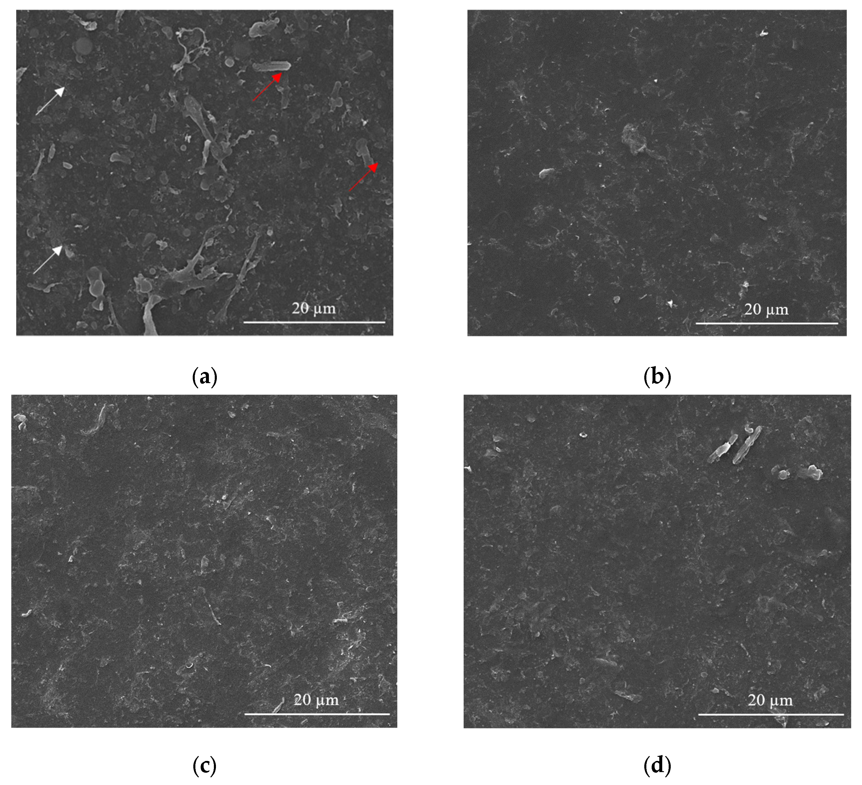
Usually, in the sensing process, as most devices require homogeneous coatings over large surfaces (over 100 µm2), MAPLE is the method of choice among the various laser deposition methods [43]. Therefore, SEM investigations carried out on CNT-Chit-FePc coatings deposited on Si(100) substrates reveal uniform coatings with different features, such as “worm”-like (white arrows in Figure 4a) and rods (red arrows in Figure 4a) that can be potentially assigned to CNT bundles and to iron phthalocyanine, respectively (please see also the Supplementary Materials for atomic force microscopy images of the features observed in SEM, i.e., Figure S3). Generally, the micrometric aggregation of composite is uniformly distributed, leading to a high specific surface area of the layers that is ideal for gas molecules adsorption [44]. For a qualitative analysis of the as-deposited layers (EDX investigation), please see Figure S4 in Supplementary Materials, where it can be seen that all the coatings are uniformly formed on the substrate.
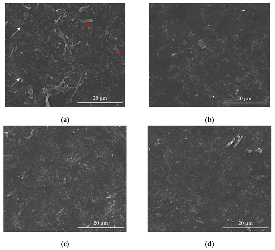
Figure 4.
SEM images for of the CNT-Chit-FePc coatings obtained on Si (100) by MAPLE from targets with different compositions: (a) (15% CNT + 1% Chit + 1% FePc) in H2O (sample A); (b) (15% CNT + 1% Chit + 0.4% FePc) in H2O (sample B); (c) (22% CNT + 1% Chit + 0.4% FePc) in H2O (sample C); and (d) (22% CNT + 1% Chit + 1% FePc) in H2O (sample D).
Samples (A and B) obtained from targets with a lower concentration of CNT (i.e., 15 wt %t) have surfaces with composite material splashes (Figure 4a,b); meanwhile, a higher CNT concentration in the target, i.e., 22 wt %, leads to a better uniformity of the layer (samples C and D) (please see Figure S5 for higher magnification images). The CNTs are uniformly scattered and embedded in the composite matrix (Figure 4c,d). The films appear to be continuous, homogenous, and without voids. This may indicate that when the CNTs, C32H16FeN8, and chitosan arrive at the sample surface, chitosan is still in the liquid state, and fill voids in the film before solidification.
The film is free of CNT protrusions from the surface, as in Figure 4a, indicating that the chitosan wets the CNT and C32H16FeN8 well in this case. The structure of the film shown in Figure 4a indicates that the growth mode is different to the films shown in Figure 4b–d. We hypothesize that the CNTs and C32H16FeN8 are “structurally reinforced” by the chitosan when they arrive at the surface, and act as nucleation and growth sites for the chitosan during the transfer process. When the CNT and C32H16FeN8 arrive on the sample surface, they are coated with chitosan, and they preserve their orientation and shape. Chitosan that is transferred subsequently and that does not encounter CNTs or C32H16FeN8 will be deposited on the substrate forming the observed chitosan film underneath. This influence of the growth mode on the morphology of the film is also explored by Wu et al. [45].
Chitosan is used as a matrix for the entrapment of a composite based on CNT and C32H16FeN8 onto C-SPE platform to fabricate an electrochemical sensor. High concentration of CNTs single dispersion and stabilization could be achieved by varieties of polysaccharides such as chitosan [46].
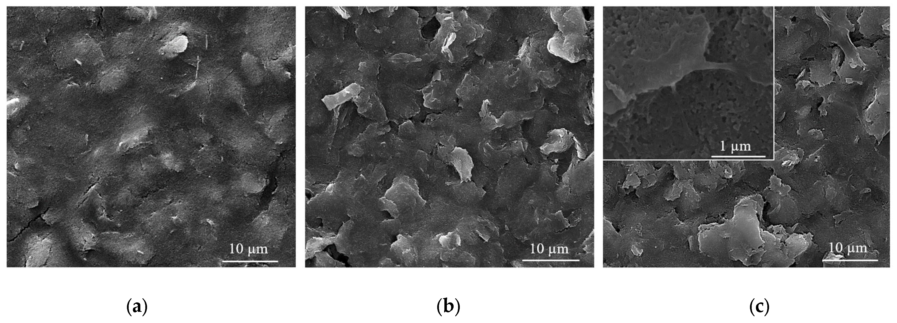
A C-SPE coated by MAPLE with a CNT-Chit-FePc film (sample C) after 200 cyclic voltammograms in the standard BR buffer at pH 4 is shown in Figure 5. The CNTs and C32H16FeN8 largely preserve the orientation and shape they acquired after deposition, while the chitosan matrix presents a non-uniform coating due to the long exposure in the BR buffer. The need to use a polymeric matrix arises from the long-term electrochemical assays and use, as well as from the necessity to have a controllable and uniform distribution of the compounds as a coating on the device, demonstrating the ability of its use to maintain the functionality of the composite compounds.
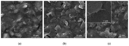
Figure 5.
SEM images of (a) bare C-SPE surface; (b) C-SPE coated with a CNT-Chit-FePc film obtained from a (22% CNT + 1% Chit + 0.4% FePc) in H2O target; (c) the same C-SPE coated with a CNT-Chit-FePc film after 200 cyclic voltammograms.
In 2007, Wang et al. investigated the solution behaviour of chitosan-wrapped CNTs [46]. The comparative characterization indicates that the electrostatic repulsive force of the charged chitosan and its derivate molecular chains could stabilize their wrapped CNTs. The aggregation of chitosan and its derivate-wrapped CNTs happened when they were discharged by changing the pH value of their suspension. When the pH value of suspension for chitosan-wrapped CNTs is higher than 6.59, the -NH3+ group deprotonated into -NH2, and a precipitate could be observed. The CNTs functionalized by chitosan derivates that contain COOH group deprotonate in an acidic environment of pH lower than 4.66 aggregate [47]. This could explain the micrometric aggregation of composite shown in Figure 5 after long exposure in the acid buffer at pH 4.0.
To sum up, we have shown that MAPLE is an efficient method to obtain composite coatings, allowing the design and development of surfaces that interact in a specific way to promote the desired processes and minimize detrimental side effects [43,48].
3.3. Voltammetric Response of Nitrite at CNT-Chit-FePc Modified C-SPE
Literature studies on electrochemical sensors based on MAPLE-deposited coatings lack important data on various important characteristics such as reproducibility, interferences, operational and storage stability, and the influence of experimental parameters such as pH, being thus far from applications in real samples.
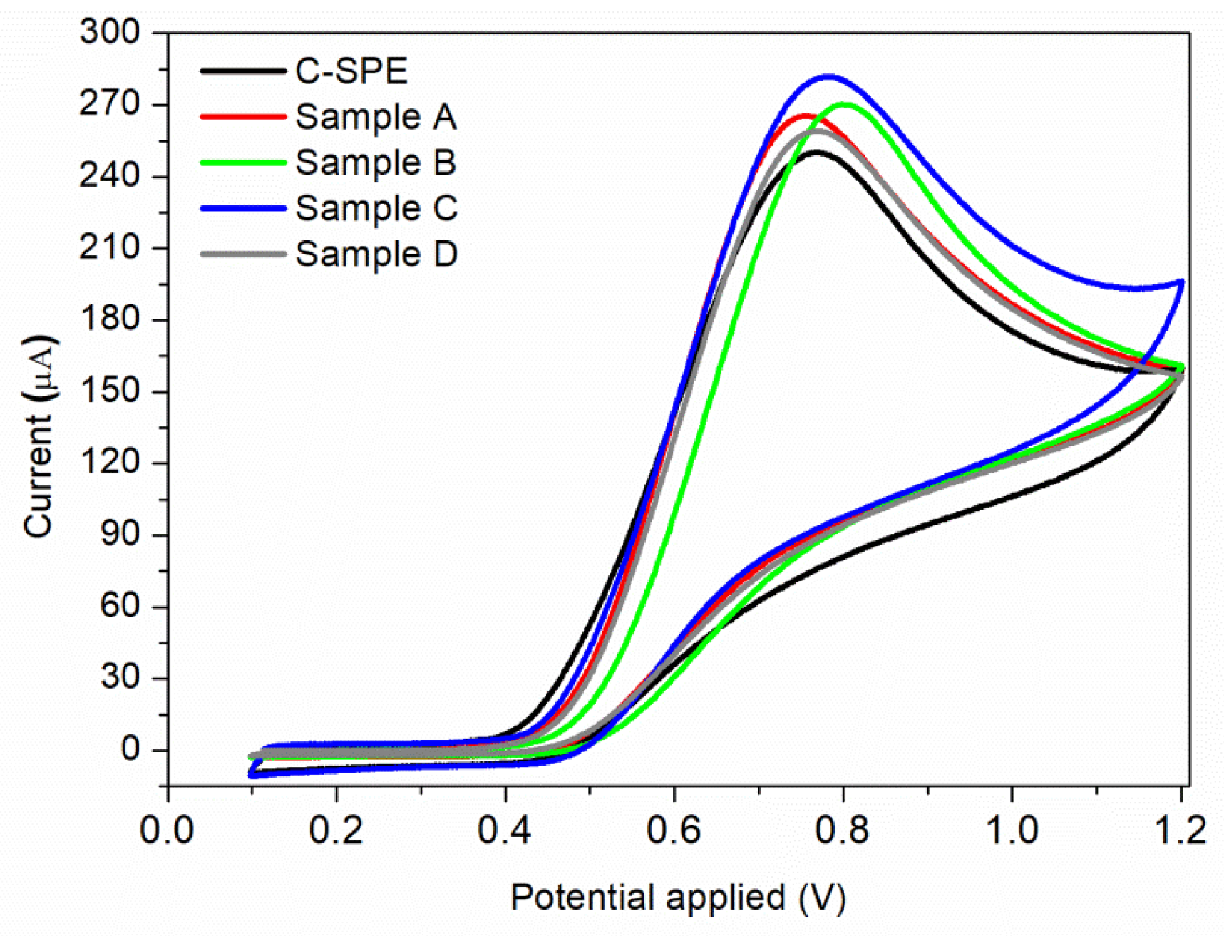
The electrocatalytic oxidation properties of nitrite with bare and MAPLE-modified commercial carbon-based screen-printed electrodes (C-SPE) were investigated. Each sensor was immersed into the electrochemical cell which was filled with the electrolyte solution having the desired nitrite content. The recorded voltammograms in BR buffer (pH = 4.0) containing 7 × 10⁻³ M nitrite, at a scan rate of 0.05 V/s, obtained for the unmodified C-SPE and samples A–D by MAPLE under different conditions, are presented in Figure 6. For all samples, only the anodic peak is present, with no cathodic peak being observed during the reverse scan, meaning that nitrite ions are irreversibly oxidized to nitrate. This effect has been found previously [8,49], where the electrochemical irreversibility behaviour of nitrite was confirmed. Modifying a simple C-SPE via MAPLE by applying a thin nanostructured coating leads to an overall improvement of the measured current, all samples showing higher values than the initial sensor. However, the highest value of the current (281 μA) is obtained for Sample C at an applied potential of 0.78 V vs. Ag/AgCl. This can be correlated to its high CNTs composition, which leads to a complex sensor having high specific surface area. Considering that the highest current was obtained for sample C, further investigations are focused on this sensor.

Figure 6.
Cyclic voltammograms of 7 × 10⁻³ M nitrite solution using a commercial C-SPE sensor, and sensors modified by MAPLE under different conditions: Sample A; Sample B; Sample C; Sample D.
The reproducibility of the modified C-SPE (with Sample C) for the determination of nitrite was evaluated by carrying out 10 voltammetric cycles in a buffer solution containing 7 × 10⁻³ M nitrite. The relative standard deviation (RSD) for the electrode response was 3%, which means that the reproducibility of the sensor is in the acceptable range.
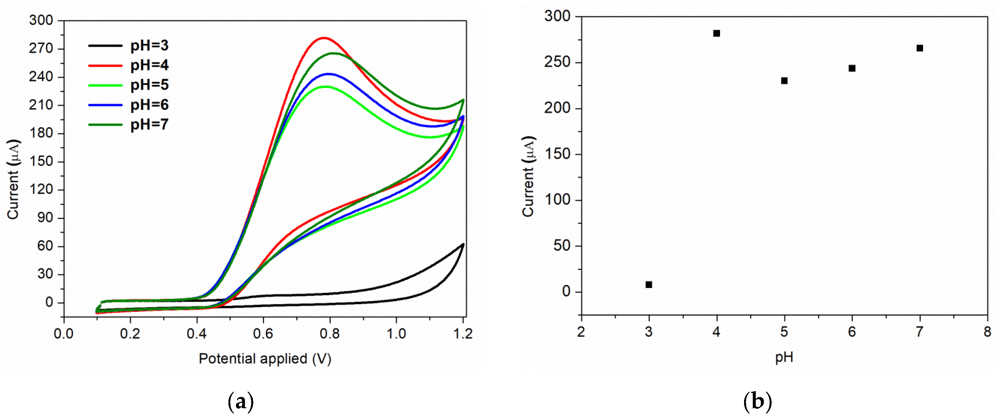
Furthermore, the nature and the pH of the electrolyte solution have a major impact on the electrochemical processes. The supporting electrolyte for this study was Briton Robinson buffer, with a pH range in acidic medium from 3 to 7. This electrolyte was chosen because it has been demonstrated previously that in BR buffer, a more sensitive and sharper anodic peak for nitrite oxidation is obtained, compared to the peak recorded in other supporting electrolytes [49]. The voltammograms recorded for 7 × 10⁻³ M nitrite, as a function of pH values, are shown in Figure 7a. As it can be observed, a very small oxidation peak is obtained when an electrolyte solution of pH = 3 is used. A possible explanation of this behaviour can be correlated to the protonation of nitrite ions or to the conversion of NO2 to NO at small pH values [8]. The highest anodic peak is obtained for pH = 4, which is the pH value used for further studies. The same result is obtained by S. Bibi et al., the authors mentioning that at pH = 4 the nitrite is electrochemically accumulated on the chitosan-CNW sensor’s surface, due to the amino and hydroxyl groups charging [14]. A relative linear increase in the anodic current is observed for pH range of 5–7, as can be seen in Figure 7b.
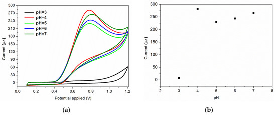
Figure 7.
(a) Effect of pH of electrolyte on the voltammetric response; (b) corresponding plot of peak current vs. pH.
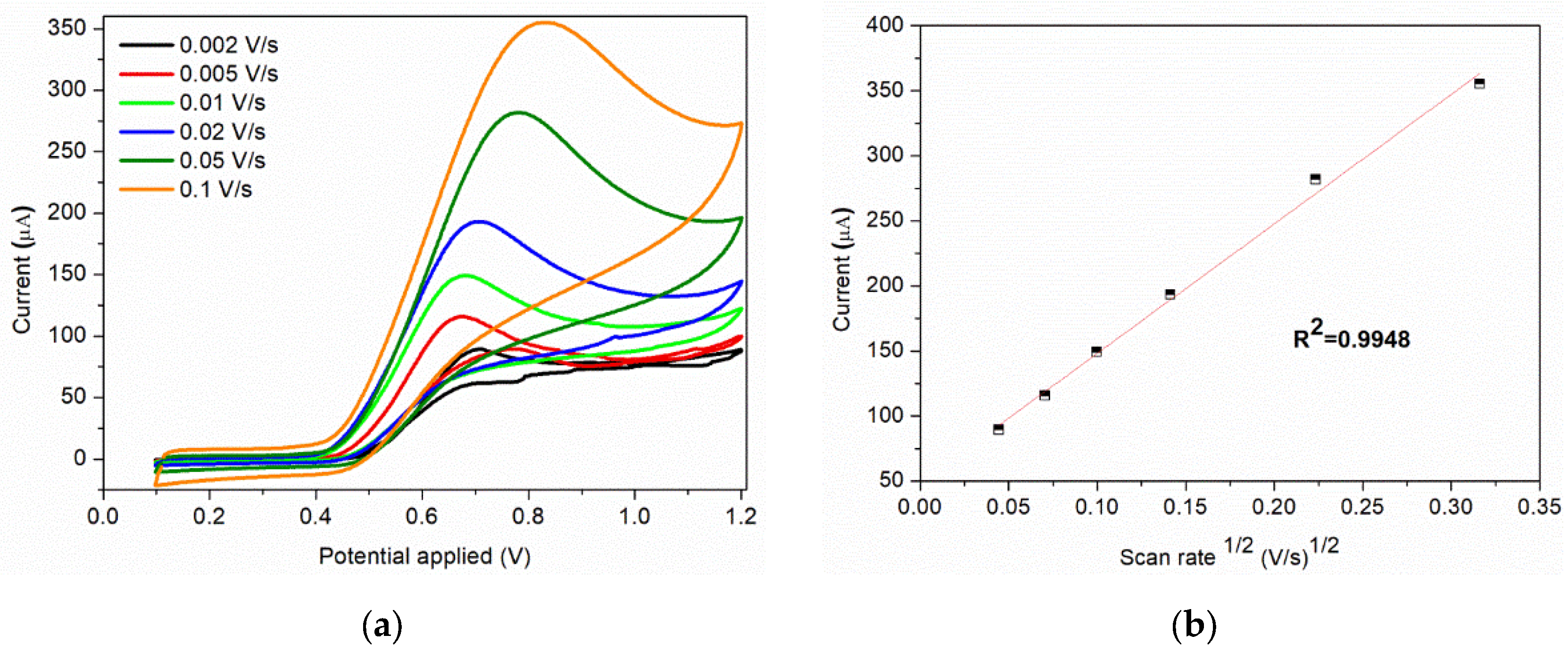
The scan rate is an important parameter that can influence the current response of nitrite. The cyclic voltammograms of sample C at different scan rates obtained in 0.1 M BR buffer (pH = 4) containing 7 × 10⁻³ M nitrite are show in Figure 8a. The anodic peak current increases with the scan rate (0.002–0.1 V/s), this increase being assisted by a shift of the peak toward more positive potentials and broadening of the peak. The peak current obtained for the anodic oxidation of nitrite ions is proportional to the square root of scan rate (Figure 8b), indicating that the process is controlled by diffusion.
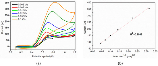
Figure 8.
(a) Cyclic voltammograms of 7 × 10⁻³ M nitrite solution at various scan rates; (b) Corresponding plot of peak current vs. square root of scan rate at 7 × 10⁻³ M nitrite.
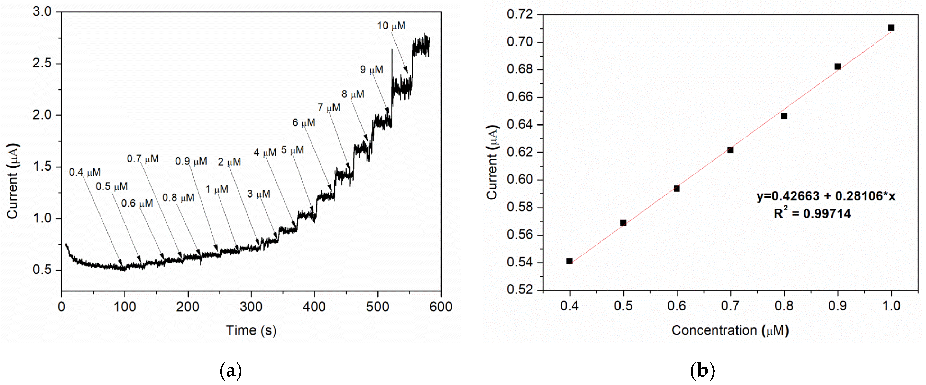
Amperometric studies were used to analyse the current response for each addition of nitrite under hydrodynamic condition. A typically steady-state amperometric response of Sample C with a successive injection of nitrite, under constant stirring, into a 0.1 M BR buffer (pH = 4) solution at an applied potential of 0.8 V vs. Ag/AgCl is presented in Figure 9a. Different volumes of buffer solution containing a specific amount of nitrite are added at 30 s intervals, the final concentration range of nitrite being 0.4–10 μM. As it can be observed, for each addition of nitrite, the current rapidly increases and the steady-state value is reached after ca. 3–4 s. A good linear correlation between the current and the nitrite concentration is obtained for 0.4–1 μM range, with a regression coefficient (R2) = 0.997 (Figure 9b).
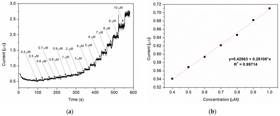
Figure 9.
(a) Amperometric response of various nitrite concentration; (b) corresponding plot of peak current vs. nitrite concentration (linear calibration plot).
The limit of detection (LOD) is found to be 0.12 μM using the formula [50]: LOD = 3Sa/b, where “Sa” is the standard deviation of the response and “b” is the slope of the calibration curve.
A comparison between different sensors tested in buffer solutions with different pH and their limit of detection is shown in Table 2. As it can be seen, in our case, good results are obtain using the modified MAPLE sensors proving that this technique is suitable for processing new functionalized composites as thin layers.
Table 2.
LOD for different sensors in different buffer solutions and pH. All sensors in Table 2 were used for NO2 detection in solutions with either BR or PBS electrolytes. In the Selectivity column are presented the interferent ions.
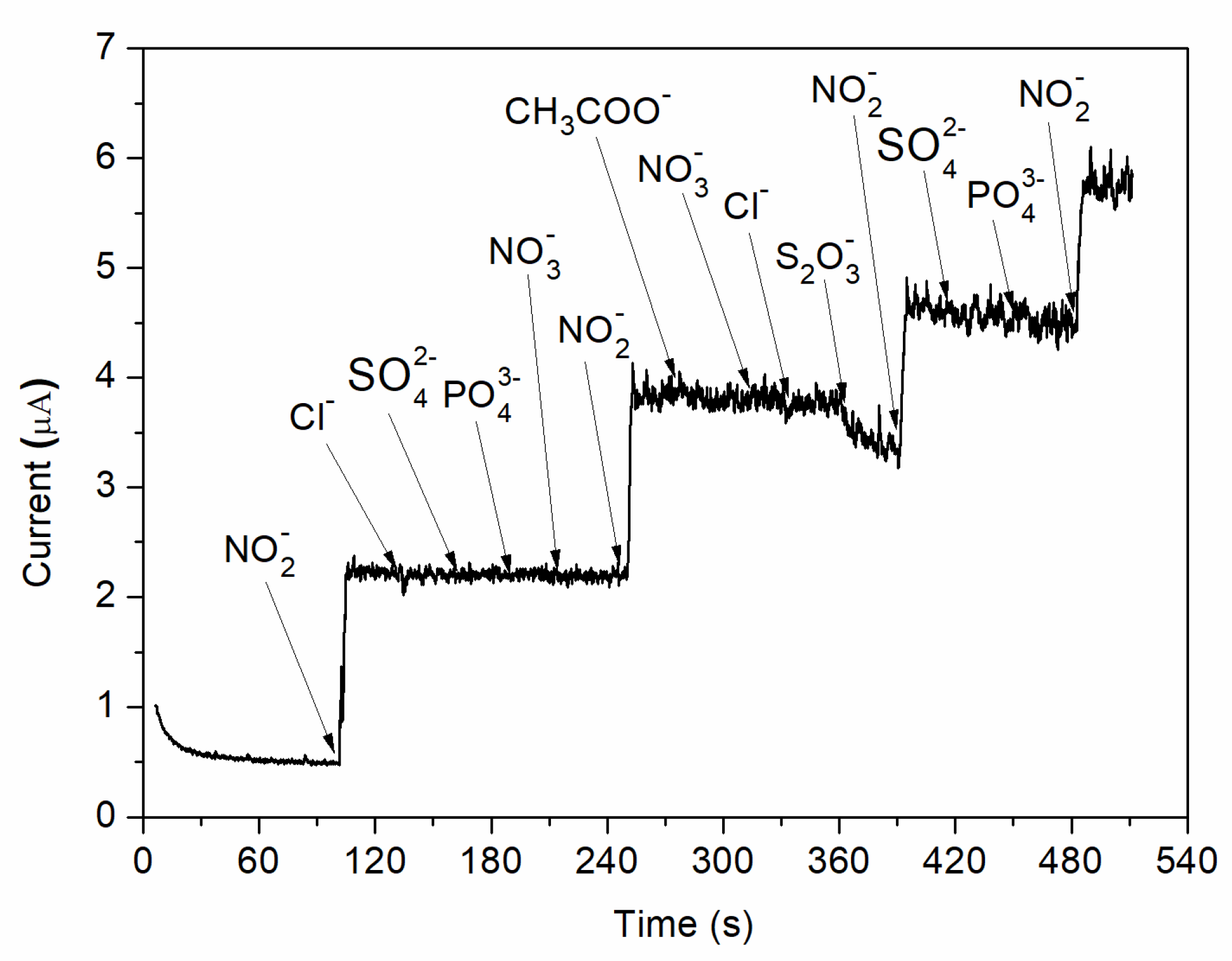
In addition, the effect of interfering species was analysed by adding different possible inferring substances in 0.1 M BR buffer (pH = 4) solution at an applied potential of 0.8 V vs. Ag/AgCl. As can be observed in Figure 10, no visible increase in the measured currents is observed when chosen ions (Cl−, SO42−, PO43−, NO3−, CH3COO−, S2O32−) are added into the electrochemical system. However, a strong increase in the amperometric current is observed when the same concentration of nitrite is injected. Therefore, the C-SPE sensor with the surface modified by MAPLE, i.e., with a carbon nanotubes–chitosan–phthalocyanine composite, shows a good selectivity for nitrite concentration.
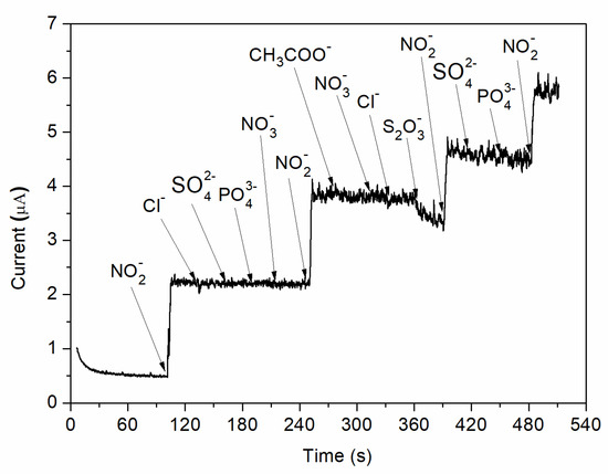
Figure 10.
Amperometric response of nitrite and various possible interfering species.
Finally, practical applications of the MAPLE processed C-SPEs were envisioned and the nitrite level in water from a well was evaluated. The real samples were used without further purification or separation procedures. Nitrite content was amperometrically detected using the same standard addition method described above. The determination results are resumed in Table 3. As can be observed, a relatively high content of nitrite is found in the analysed water. Good percentage recoveries in the range of 98–115% are obtained, meaning that nitrites can be accurately determined in real samples.
Table 3.
Determination of nitrite level in water from a well with a C-SPE coated by MAPLE with CNT-Chit-FePc composite.
4. Conclusions
The main challenge in the field of electrochemical sensors is the development and application of multifunctional materials with specific properties or functions. Matrix-assisted pulsed laser evaporation (MAPLE) offers unique advantages in obtaining composite coatings without noticeable chemical/structural damages on any substrate. In this work, we applied MAPLE for the fabrication of new composite coatings based on carbon nanotubes (CNTs), chitosan (Chit), and iron (II) phthalocyanine (FePc) which were deposited as thin films onto commercial carbon-based screen-printed electrodes (C-SPE). The goal of the work was to demonstrate the potential of the newly developed C-SPE for the detection of low concentrations of nitrites in water.
Following MAPLE, we obtained CNT-Chit-FePC homogeneous composite coatings, with different “worm”- and “rod”-like features that can be assigned to CNT bundles and to iron phthalocyanine (FePc). The MAPLE processed composite was uniformly distributed onto the C-SPEs, leading to a high specific surface area of the layers, making it ideal for gas molecules adsorption.
In addition, the C-SPE’s modified by MAPLE were employed for the voltammetric determination of nitrite. The sensor measurements were carried out in a Briton Robinson buffer solution at different pH values. Different nitrite concentrations were added into the electrolyte solution, and, by applying an external potential, the nitrite ions (NO2−) were oxidized, at the sensor surface, to nitrate ions (NO3−). The oxidation peak appears at 0.8 V vs. Ag/AgCl. This potential was used for further amperometric detection of nitrite ions, where it can be observed that for each addition of nitrite content, the generated current increases. We assume that the combined effect of CNT, chitosan, and iron (II) phthalocyanine improves the electrochemical response towards the oxidation of nitrite. This is emphasized by the ability of CNT-Chit-FePc composite produced by MAPLE to adsorb rapidly the nitrite at the surface leading to the increase in sensitivity towards nitrite.
Moreover, the C-SPE fabricated from the starting target 22% CNT + 1% Chit + 0.4% C32H16FeN8 (Sample C) shows the highest anodic current for nitrite oxidation. The limit of detection for this sensor is 0.12 µM, meaning that the resulting sensor can be successfully used even for the detection of nitrite traces. The same electrode has an excellent selectivity, toward nitrite ions in comparison to other common anions, none of them showing an amperometric response. In addition, the C-SPE can be successfully used for real sample analysis.
To sum up, this work shows an important direction for the development of nitrite detection sensors based on novel hybrid composites (i.e., carbon nanotubes, chitosan, and iron (II) phthalocyanine) fabricated by MAPLE. Practical application aspects of the proposed sensor include detection of nitrites in the food industry or in medical applications. There are additional questions for future research, such as whether we can detect nitrites in other environments (i.e., blood) or how the sensor performances would depend on the topography and surface chemistry/wettability of the MAPLE processed composite coatings.
Supplementary Materials
The following supporting information can be downloaded at: https://www.mdpi.com/article/10.3390/nano12071138/s1, Figure S1. AFM image of Sample C taken at the edge of the thin layer. Figure S2. (a) FTIR spectra of powder chitosan (as-received from Sigma Aldrich) [31,32,51,52]; Figure S2. (b) FTIR spectra of C32H16FeN8 (as-received from Sigma Aldrich) [33]; Figure S2. (c) FTIR spectra of CNTs (as-received from Sigma Aldrich) [34,35,36,53,54,55]; Figure S3. AFM images of the samples A, B, C and D. Figure S4. EDS spectrum of the MAPLE processed coatings. Figure S5. SEM images of the CNT-Chit-FePc coatings obtained on Si(100) by MAPLE from targets with different compositions: (a) 15% CNT + 1% Chit + 1% FePc in H2O (sample A); (b) 15% CNT + 1% Chit + 0.4% FePc in H2O (sample B); (c) 22% CNT + 1% Chit + 0.4% FePc) in H2O (sample C) and (d) 22% CNT + 1% Chit + 1% FePc in H2O (sample D).
Author Contributions
Conceptualization, M.F. and A.P.-P.; Investigation, C.C., F.A., A.B., S.B. and T.T.; Writing—original draft, C.C., F.A. and A.B.; Writing—review and editing, A.P.-P. and M.D. All authors have read and agreed to the published version of the manuscript.
Funding
This work was supported by a grant of the Romanian Ministry of Research, Innovation and Digitization, CNCS/CCCDI—UEFISCDI, project number PN-III-P2-2.1-PED-2019-1480 (AWISEM) within PNCDI III and the Romanian National Nucleus Program.
Institutional Review Board Statement
Not applicable.
Informed Consent Statement
Not applicable.
Data Availability Statement
Not applicable.
Conflicts of Interest
The authors declare no conflict of interest.
References
- Ge, L.; Han, Z.; Gao, Y.-Q.; Zhou, C.-J.; Wang, D.-H.; Ma, Y.-Z.; Liang, C.-G. Sodium nitrite negatively affects reproductive ability and offspring survival in female mice. Toxicology 2019, 427, 152284. [Google Scholar] [CrossRef] [PubMed]
- Huang, C.-P.; Wang, H.-W.; Chiu, P.-C. Nitrate reduction by metallic iron. Water Res. 1998, 32, 2257–2264. [Google Scholar] [CrossRef]
- World Health Organization. Guidelines for Drinking-Water Quality: Recommendations; World Health Organization: Geneva, Switzerland, 2004. [Google Scholar]
- Li, X.; Ping, J.; Ying, Y. Recent developments in carbon nanomaterial-enabled electrochemical sensors for nitrite detection. TrAC Trends Anal. Chem. 2019, 113, 1–12. [Google Scholar] [CrossRef]
- Xu, X.; Li, C.-H.; Zhang, H.; Guo, X.-M. Construction of Electrochemical and Photoelectrochemical Sensing Platform Based on Porphyrinic Metal-Organic Frameworks for Determination of Ascorbic Acid. Nanomaterials 2022, 12, 482. [Google Scholar] [CrossRef]
- Soulis, D.; Trigazi, M.; Tsekenis, G.; Chandrinou, C.; Klinakis, A.; Zergioti, I. Facile and Low-Cost SPE Modification Towards Ultra-Sensitive Organophosphorus and Carbamate Pesticide Detection in Olive Oil. Molecules 2020, 25, 4988. [Google Scholar] [CrossRef]
- Bonciu, A.F.; Filipescu, M.; Voicu, S.I.; Lippert, T.; Palla-Papavlu, A. Facile Fabrication of Hybrid Carbon Nanotube Sensors by Laser Direct Transfer. Nanomaterials 2021, 11, 2604. [Google Scholar] [CrossRef]
- Afkhami, A.; Soltani-Felehgari, F.; Madrakian, T.; Ghaedi, H. Surface decoration of multi-walled carbon nanotubes modified carbon paste electrode with gold nanoparticles for electro-oxidation and sensitive determination of nitrite. Biosens. Bioelectron. 2013, 51, 379–385. [Google Scholar] [CrossRef]
- Thirumalraj, B.; Palanisamy, S.; Chen, S.-M.; Zhao, D.-H. Amperometric detection of nitrite in water samples by use of electrodes consisting of palladium-nanoparticle-functionalized multi-walled carbon nanotubes. J. Colloid Interface Sci. 2016, 478, 413–420. [Google Scholar] [CrossRef]
- Zhang, Y.; Nie, J.; Wei, H.; Xu, H.; Wang, Q.; Cong, Y.; Tao, J.; Chu, L.; Zhou, Y.; Wu, X. Electrochemical detection of nitrite ions using Ag/Cu/MWNT nanoclusters electrodeposited on a glassy carbon electrode. Sens. Actuators B Chem. 2018, 258, 1107–1116. [Google Scholar] [CrossRef]
- Wang, C.; Yuan, R.; Chai, Y.; Chen, S.; Zhang, Y.; Hu, F.; Zhang, M. Non-covalent iron(III)-porphyrin functionalized multi-walled carbon nanotubes for the simultaneous determination of ascorbic acid, dopamine, uric acid and nitrite. Electrochim. Acta 2011, 62, 109–115. [Google Scholar] [CrossRef]
- Karrat, A.; Amine, A. Recent Advances in Chitosan-Based Electrochemical Sensors and Biosensors. Arab. J. Chem. Environ. Res. 2020, 7, 66–93. [Google Scholar]
- Ryu, H.; Thompson, D.; Huang, Y.; Li, B.; Lei, Y. Electrochemical sensors for nitrogen species: A review. Sens. Actuators Rep. 2020, 2, 100022. [Google Scholar] [CrossRef]
- Bibi, S.; Zaman, M.I.; Niaz, A.; Rahim, A.; Nawaz, M.; Arian, M.B. Voltammetric determination of nitrite by using a multiwalled carbon nanotube paste electrode modified with chitosan-functionalized silver nanoparticles. Mikrochim. Acta 2019, 186, 595. [Google Scholar] [CrossRef] [PubMed]
- Li, S.; Qu, J.; Wang, Y.; Qu, J.; Wang, H. A novel electrochemical sensor based on carbon nanoparticle composite films for the determination of nitrite and hydrogen peroxide. Anal. Methods 2016, 8, 4204–4210. [Google Scholar] [CrossRef]
- Bai, Z.; Zhou, C.; Gao, N.; Pang, H.; Ma, H. A chitosan–Pt nanoparticles/carbon nanotubes-doped phosphomolybdate nanocomposite as a platform for the sensitive detection of nitrite in tap water. RSC Adv. 2015, 6, 937–946. [Google Scholar] [CrossRef]
- Wang, T.; Xu, X.; Wang, C.; Li, Z.; Li, D. A Novel Highly Sensitive Electrochemical Nitrite Sensor Based on a AuNPs/CS/Ti3C2 Nanocomposite. Nanomaterials 2022, 12, 397. [Google Scholar] [CrossRef]
- Wang, T.; Wang, C.; Xu, X.; Li, Z.; Li, D. One-Step Electrodeposition Synthesized Aunps/Mxene/ERGO for Selectivity Nitrite Sensing. Nanomaterials 2021, 11, 1892. [Google Scholar] [CrossRef]
- Xian, H.; Wang, P.; Zhou, Y.; Lu, Q.; Wu, S.; Li, Y.; Wang, L. Electrochemical determination of nitrite via covalent immobilization of a single-walled carbon nanotubes and single stranded deoxyribonucleic acid nanocomposite on a glassy carbon electrode. Mikrochim. Acta 2010, 171, 63–69. [Google Scholar] [CrossRef]
- Yang, S.; Xia, B.; Zeng, X.; Luo, S.; Wei, W.; Liu, X. Fabrication of DNA functionalized carbon nanotubes/Cu2+ complex by one-step electrodeposition and its sensitive determination of nitrite. Anal. Chim. Acta 2010, 667, 57–62. [Google Scholar] [CrossRef]
- Dumitrescu, L.N.; Ionita, E.-R.; Birjega, R.; Lazea-Stoyanova, A.; Ionita, M.-D.; Epurescu, G.; Banici, A.-M.; Brajnicov, S.; Andrei, F.; Matei, A. Kaolinite Thin Films Grown by Pulsed Laser Deposition and Matrix Assisted Pulsed Laser Evaporation. Nanomaterials 2022, 12, 546. [Google Scholar] [CrossRef]
- Yang, S.; Zhang, J. Matrix-Assisted Pulsed Laser Evaporation (MAPLE) technique for deposition of hybrid nanostructures. Front. Nanosci. Nanotechnol. 2017, 3, 1–9. [Google Scholar] [CrossRef] [Green Version]
- Palla-Papavlu, A.; Dinca, V.; Filipescu, M.; Dinescu, M. Matrix-Assisted Pulsed Laser Evaporation of Organic Thin Films: Applications in Biology and Chemical Sensors. In Laser Ablation–From Fundamentals to Applications; Itina, T.E., Ed.; IntechOpen: London, UK, 2017; ISBN 978-953-51-3699-6. [Google Scholar]
- Ferreira Calvete, M.J.; Hanack, M. Symmetrically and Unsymmetrically Substituted Phthalocyanines. In Materials Syntheses: A Practical Guide; Schubert, U., Hüsing, N., Laine, R.M., Eds.; Springer: Vienna, Austria, 2008; pp. 217–225. ISBN 978-3-211-75125-1. [Google Scholar]
- DiChristina, T.J. Effects of nitrate and nitrite on dissimilatory iron reduction by Shewanella putrefaciens 200. J. Bacteriol. 1992, 174, 1891–1896. [Google Scholar] [CrossRef] [PubMed] [Green Version]
- Craciun, C.; Filipescu, M.; Palla-Papavlu, A.; Brajnicov, S.; Tozar, T.; Scheaua, F.; Bonciu, A.; Nedelcut, F.; Dinescu, M. Sensing Membranes based on CNT Nanocomposites Processing for Air and Water Monitoring. In Proceedings of the 2021 International Workshop on Metrology for the Sea; Learning to Measure Sea Health Parameters (MetroSea), Reggio Calabria, Italy, 4–6 October 2021; pp. 183–188. [Google Scholar] [CrossRef]
- Zeng, Z.; Fang, X.; Miao, W.; Liu, Y.; Maiyalagan, T.; Mao, S. Electrochemically Sensing of Trichloroacetic Acid with Iron(II) Phthalocyanine and Zn-Based Metal Organic Framework Nanocomposites. ACS Sens. 2019, 4, 1934–1941. [Google Scholar] [CrossRef] [PubMed]
- Kaelble, D.H. Dispersion-polar surface tension properties of organic solids. J. Adhes. 1970, 2, 66–81. [Google Scholar] [CrossRef]
- Owens, D.K.; Wendt, R.C. Estimation of the surface free energy of polymers. J. Appl. Polym. Sci. 1969, 13, 1741–1747. [Google Scholar] [CrossRef]
- Habenicht, G. Kleben der Kunststoffe und weiterer nichtmetallischer Werkstoffe. In Kleben: Grundlagen, Technologie, Anwendungen; Habenicht, G., Ed.; Springer: Berlin/Heidelberg, Germany, 1997; pp. 583–648. ISBN 978-3-662-08087-0. [Google Scholar]
- Fernandes Queiroz, M.; Melo, K.R.T.; Sabry, D.A.; Sassaki, G.L.; Rocha, H.A.O. Does the Use of Chitosan Contribute to Oxalate Kidney Stone Formation? Mar. Drugs 2014, 13, 141–158. [Google Scholar] [CrossRef]
- Shanmugam, A.; Kathiresan, K.; Nayak, L. Preparation, characterization and antibacterial activity of chitosan and phosphorylated chitosan from cuttlebone of Sepia kobiensis (Hoyle, 1885). Biotechnol. Rep. 2015, 9, 25–30. [Google Scholar] [CrossRef] [Green Version]
- Neamtu, M.; Nadejde, C.; Brinza, L.; Dragos, O.; Gherghel, D.; Paul, A. Iron phthalocyanine-sensitized magnetic catalysts for BPA photodegradation. Sci. Rep. 2020, 10, 5376. [Google Scholar] [CrossRef]
- Kim, U.J.; Furtado, C.A.; Liu, X.; Chen, G.; Eklund, P.C. Raman and IR Spectroscopy of Chemically Processed Single-Walled Carbon Nanotubes. J. Am. Chem. Soc. 2005, 127, 15437–15445. [Google Scholar] [CrossRef]
- Bantignies, J.-L.; Sauvajol, J.-L.; Rahmani, A.; Flahaut, E. Infrared-active phonons in carbon nanotubes. Phys. Rev. B 2006, 74, 195425. [Google Scholar] [CrossRef] [Green Version]
- Ţucureanu, V.; Matei, A.; Avram, A.M. FTIR Spectroscopy for Carbon Family Study. Crit. Rev. Anal. Chem. 2016, 46, 502–520. [Google Scholar] [CrossRef] [PubMed]
- Long, D.; Wu, G.; Zhu, G. Noncovalently Modified Carbon Nanotubes with Carboxymethylated Chitosan: A Controllable Donor-Acceptor Nanohybrid. Int. J. Mol. Sci. 2008, 9, 120–130. [Google Scholar] [CrossRef] [PubMed] [Green Version]
- Xie, Y.; Soh, A. Investigation of non-covalent association of single-walled carbon nanotube with amylose by molecular dynamics simulation. Mater. Lett. 2005, 59, 971–975. [Google Scholar] [CrossRef]
- Gurevitch, I.; Srebnik, S. Monte Carlo simulation of polymer wrapping of nanotubes. Chem. Phys. Lett. 2007, 444, 96–100. [Google Scholar] [CrossRef]
- Iamsamai, C.; Hannongbua, S.; Ruktanonchai, U.; Soottitantawat, A.; Dubas, S. The effect of the degree of deacetylation of chitosan on its dispersion of carbon nanotubes. Carbon 2010, 48, 25–30. [Google Scholar] [CrossRef]
- Almeida, E.V.R.; Frollini, E.; Castellan, A.; Coma, V. Chitosan, sisal cellulose, and biocomposite chitosan/sisal cellulose films prepared from thiourea/NaOH aqueous solution. Carbohydr. Polym. 2010, 80, 655–664. [Google Scholar] [CrossRef]
- Chen, F.; Shi, X.; Chen, X.; Chen, W. An iron (II) phthalocyanine/poly(vinylidene fluoride) composite membrane with antifouling property and catalytic self-cleaning function for high-efficiency oil/water separation. J. Membr. Sci. 2018, 552, 295–304. [Google Scholar] [CrossRef]
- Bonciu, A.; Vasilescu, A.; Dinca, V.; Peteu, S.F. Interfaces obtained by MAPLE for chemical and biosensors applications. Sens. Actuators Rep. 2021, 3, 100040. [Google Scholar] [CrossRef]
- Wang, Y.; Yeow, J.T.W. A Review of Carbon Nanotubes-Based Gas Sensors. J. Sens. 2009, 2009, 493904. [Google Scholar] [CrossRef]
- Wu, P.K.; Fitz-Gerald, J.; Pique, A.; Chrisey, D.; McGill, R. Deposition of Nanotubes and Nanotube Composites Using Matrix-Assisted Pulsed Laser Evaporation. MRS Proc. 2000, 617, 23. [Google Scholar] [CrossRef] [Green Version]
- Zhang, J.; Wang, Q.; Wang, L.; Wang, A. Manipulated dispersion of carbon nanotubes with derivatives of chitosan. Carbon 2007, 45, 1917–1920. [Google Scholar] [CrossRef]
- Lu, L.; Hu, Y.; Chang, C.; Chen, W. Carbon Nanotubes Engineering Assisted by Natural Biopolymers; IntechOpen: London, UK, 2011; ISBN 978-953-307-498-6. [Google Scholar]
- Rose, O.; Bonciu, A.; Marascu, V.; Matei, A.; Liu, Q.; Rusen, L.; Dinca, V.; Dinu, C. Thin Films of Metal-Organic Framework Interfaces Obtained by Laser Evaporation. Nanomaterials 2021, 11, 1367. [Google Scholar] [CrossRef] [PubMed]
- Jiang, L.; Wang, R.; Li, X.; Jiang, L.; Lu, G. Electrochemical oxidation behavior of nitrite on a chitosan-carboxylated multiwall carbon nanotube modified electrode. Electrochem. Commun. 2005, 7, 597–601. [Google Scholar] [CrossRef]
- Shrivastava, A.; Gupta, V.B. Methods for the determination of limit of detection and limit of quantitation of the analytical methods. Chron. Young Sci. 2011, 2, 21–25. [Google Scholar] [CrossRef]
- Lim, S.-H.; Hudson, S.M. Synthesis and Antimicrobial Activity of a Water-Soluble Chitosan Derivative with a Fiber-Reactive Group. Carbohydr. Res. 2004, 339, 313–319. [Google Scholar] [CrossRef]
- Song, C.; Yu, H.; Zhang, M.; Yang, Y.; Zhang, G. Physicochemical Properties and Antioxidant Activity of Chitosan from the Blowfly Chrysomya megacephala Larvae. Int. J. Biol. Macromol. 2013, 60, 347–354. [Google Scholar] [CrossRef]
- Branca, C.; Frusteri, F.; Magazù, V.; Mangione, A. Characterization of Carbon Nanotubes by TEM and Infrared Spectroscopy. J. Phys. Chem. B 2004, 108, 3469–3473. [Google Scholar] [CrossRef]
- Hussain, S.; Jha, P.; Chouksey, A.; Raman, R.; Islam, S.S.; Islam, T.; Choudhary, P.K. Spectroscopic Investigation of Modified Single Wall Carbon Nanotube (SWCNT). J. Modern Phys. 2011, 2, 538–543. [Google Scholar] [CrossRef] [Green Version]
- Jain, S.M.; Cesano, F.; Scarano, D.; Edvinsson, T. Resonance Raman and IR Spectroscopy of Aligned Carbon Nanotube Arrays with Extremely Narrow Diameters Prepared with Molecular Catalysts on Steel Substrates. Phys. Chem. Chem. Phys. 2017, 19, 30667–30674. [Google Scholar] [CrossRef] [Green Version]

Publisher’s Note: MDPI stays neutral with regard to jurisdictional claims in published maps and institutional affiliations. |
© 2022 by the authors. Licensee MDPI, Basel, Switzerland. This article is an open access article distributed under the terms and conditions of the Creative Commons Attribution (CC BY) license (https://creativecommons.org/licenses/by/4.0/).