
Kaolinite Thin Films Grown by Pulsed Laser Deposition and Matrix Assisted Pulsed Laser Evaporation

 , , ,
, , ,
Abstract
:1. Introduction
2. Materials and Methods
2.1. Materials
2.2. Lamellar Thin Films Deposition
2.3. Characterization
3. Results and Discussion
4. Conclusions
Author Contributions
Funding
Data Availability Statement
Acknowledgments
Conflicts of Interest
References
- Ismadji, S.; Soetaredjo, F.E.; Ayucitra, A. Natural clay minerals as environmental cleaning agents. In Clay Materials for Environmental Remediation; Ismadji, S., Soetaredjo, F.E., Ayucitra, A., Eds.; Springer Briefs in Molecular Science; Springer International Publishing: Cham, Switzerland, 2015; pp. 5–37. ISBN 978-3-319-16712-1. [Google Scholar]
- Bø Hunvik, K.W.; Loch, P.; Wallacher, D.; Kirch, A.; Cavalcanti, L.P.; Rieß, M.; Daab, M.; Josvanger, V.; Grätz, S.; Yokaichiya, F.; et al. CO2 adsorption enhanced by tuning the layer charge in a clay mineral. Langmuir 2021, 37, 14491–14499. [Google Scholar] [CrossRef] [PubMed]
- Leiviskä, T.; Gehör, S.; Eijärvi, E.; Sarpola, A.; Tanskanen, J. Characteristics and potential applications of coarse clay fractions from puolanka, Finland. Open Eng. 2012, 2, 239–247. [Google Scholar] [CrossRef]
- Ghadiri, M.; Chrzanowski, W.; Rohanizadeh, R. Biomedical applications of cationic clay minerals. RSC Adv. 2015, 5, 29467–29481. [Google Scholar] [CrossRef]
- Letaief, S.; Tonle, I.K.; Diaco, T.; Detellier, C. Nanohybrid materials from interlayer functionalization of kaolinite. Application to the electrochemical preconcentration of cyanide. Appl. Clay Sci. 2008, 42, 95–101. [Google Scholar] [CrossRef]
- Dim, P.E.; Mustapha, L.S.; Termtanun, M.; Okafor, J.O. Adsorption of chromium (VI) and iron (III) ions onto acid-modified kaolinite: Isotherm, kinetics and thermodynamics studies. Arab. J. Chem. 2021, 14, 103064. [Google Scholar] [CrossRef]
- Selvan, B.K.; Thiyagarajan, K.; Das, S.; Jaya, N.; Jabasingh, S.A.; Saravanan, P.; Rajasimman, M.; Vasseghian, Y. Synthesis and characterization of nano zerovalent iron-kaolin clay (NZVI-Kaol) composite polyethersulfone (PES) membrane for the efficacious As2O3 removal from potable water samples. Chemosphere 2022, 288, 132405. [Google Scholar] [CrossRef]
- Nguelo, B.B.; Fomat, M.F.; Dedzo, G.K.; Ngameni, E. Catalytic detection of iodide at cationic kaolinite modified gold electrode in presence of thiosulfate. Electroanalysis 2020, 32, 1417–1425. [Google Scholar] [CrossRef]
- Al-Yaseri, A.; Wolff-Boenisch, D.; Fauziah, C.A.; Iglauer, S. Hydrogen wettability of clays: Implications for underground hydrogen storage. Int. J. Hydrog. Energy 2021, 46, 34356–34361. [Google Scholar] [CrossRef]
- Dedzo, G.K.; Letaief, S.; Detellier, C. Kaolinite–ionic liquid nanohybrid materials as electrochemical sensors for size-selective detection of anions. J. Mater. Chem. 2012, 22, 20593–20601. [Google Scholar] [CrossRef]
- Abdullah, O. Effect of kaolin light concentration on optical characteristic of PVA films. Asian Trans. Sci. Amp. Technol. 2011, 1, 12–15. [Google Scholar]
- Brooksby, P.A.; Downard, A.J. Electrochemical and atomic force microscopy study of carbon surface modification via diazonium reduction in aqueous and acetonitrile solutions. Langmuir 2004, 20, 5038–5045. [Google Scholar] [CrossRef] [PubMed]
- Lackner, J.M.; Waldhauser, W.; Ebner, R.; Major, B.; Schöberl, T. pulsed laser deposition of titanium oxide coatings at room temperature—Structural, mechanical and tribological properties. Surf. Coat. Technol. 2004, 180–181, 585–590. [Google Scholar] [CrossRef]
- Filipescu, M.; Papavlu, A.P.; Dinescu, M. Functional Metal Oxide Thin Films Grown by Pulsed Laser Deposition; IntechOpen: London, UK, 2016; ISBN 978-953-51-2446-7. [Google Scholar]
- Cichetto, L.; Sergeenkov, S.; Diaz, J.C.C.A.; Longo, E.; Araújo-Moreira, F.M. Influence of substrate on structural and transport properties of LaNiO3 thin films prepared by pulsed laser deposition. AIP Adv. 2017, 7, 025005. [Google Scholar] [CrossRef] [Green Version]
- Masood, K.B.; Kumar, P.; Malik, M.A.; Singh, J. A comprehensive tutorial on the pulsed laser deposition technique and developments in the fabrication of low dimensional systems and nanostructures. Emergent Mater. 2021, 4, 737–754. [Google Scholar] [CrossRef]
- Liu, Z. 4.09—Laser applied coatings. In Shreir’s Corrosion; Cottis, B., Graham, M., Lindsay, R., Lyon, S., Richardson, T., Scantlebury, D., Stott, H., Eds.; Elsevier: Oxford, UK, 2010; pp. 2622–2635. ISBN 978-0-444-52787-5. [Google Scholar]
- Orava, J.; Kohoutek, T.; Wagner, T. 9—Deposition techniques for chalcogenide thin films. In Chalcogenide Glasses; Adam, J.-L., Zhang, X., Eds.; Woodhead Publishing: Cambridge, UK, 2014; pp. 265–309. ISBN 978-0-85709-345-5. [Google Scholar]
- Birjega, R.; Matei, A.; Filipescu, M.; Stokker-Cheregi, F.; Luculescu, C.; Colceag, D.; Zavoianu, R.; Pavel, O.D.; Dinescu, M. The investigation of Ni–Al and Co–Al based layered double hydroxides and their derived mixed oxides thin films deposited by pulsed laser deposition. Appl. Surf. Sci. 2013, 278, 122–126. [Google Scholar] [CrossRef]
- Birjega, R.; Matei, A.; Mitu, B.; Ionita, M.D.; Filipescu, M.; Stokker-Cheregi, F.; Luculescu, C.; Dinescu, M.; Zavoianu, R.; Pavel, O.D.; et al. Layered double hydroxides/polymer thin films grown by matrix assisted pulsed laser evaporation. Thin Solid Film. 2013, 543, 63–68. [Google Scholar] [CrossRef]
- Vlad, A.; Birjega, R.; Matei, A.; Luculescu, C.; Mitu, B.; Dinescu, M.; Zavoianu, R.; Pavel, O.D. Retention of heavy metals on layered double hydroxides thin films deposited by pulsed laser deposition. Appl. Surf. Sci. 2014, 302, 99–104. [Google Scholar] [CrossRef]
- Matei, A.; Birjega, R.; Nedelcea, A.; Vlad, A.; Colceag, D.; Ionita, M.D.; Luculescu, C.; Dinescu, M.; Zavoianu, R.; Pavel, O.D. Mg–Al layered double hydroxides (LDHs) and their derived mixed oxides grown by laser techniques. Appl. Surf. Sci. 2011, 257, 5308–5311. [Google Scholar] [CrossRef]
- Matei, A.; Birjega, R.; Vlad, A.; Filipescu, M.; Nedelcea, A.; Luculescu, C.; Zavoianu, R.; Pavel, O.D.; Dinescu, M. Adsorption properties of Mg–Al layered double hydroxides thin films grown by laser based techniques. Appl. Surf. Sci. 2012, 258, 9466–9470. [Google Scholar] [CrossRef]
- Matei, A.; Birjega, R.; Vlad, A.; Luculescu, C.; Epurescu, G.; Stokker-Cheregi, F.; Dinescu, M.; Zavoianu, R.; Pavel, O.D. Pulsed laser deposition of Mg–Al layered double hydroxide with ag nanoparticles. Appl. Phys. A 2013, 110, 841–846. [Google Scholar] [CrossRef]
- Birjega, R.; Matei, A.; Marascu, V.; Vlad, A.; Ionita, M.D.; Dinescu, M.; Zăvoianu, R.; Corobea, M.C. Stearic acid/layered double hydroxides composite thin films deposited by combined laser techniques. Molecules 2020, 25, 4097. [Google Scholar] [CrossRef] [PubMed]
- Baciu, D.D.; Matei, A.; Visan, T. Extraction procedure and cyclic voltammetry assay for detection of monosodium glutamate from different processed food sources. Rev. Chim. 2020, 71, 63–71. [Google Scholar] [CrossRef]
- Owens, D.K.; Wendt, R.C. Estimation of the surface free energy of polymers. J. Appl. Polym. Sci. 1969, 13, 1741–1747. [Google Scholar] [CrossRef]
- Kaelble, D.H. Dispersion-polar surface tension properties of organic solids. J. Adhes. 1970, 2, 66–81. [Google Scholar] [CrossRef]
- Aparicio, P.; Galán, E. Mineralogical interference on kaolinite crystallinity index measurements. Clays Clay Miner. 1999, 47, 12–27. [Google Scholar] [CrossRef]
- Guggenheim, S.; Adams, J.M.; Bain, D.C.; Bergaya, F.; Brigatti, M.F.; Drits, V.A.; Formoso, M.L.L.; Galán, E.; Kogure, T.; Stanjek, H. Summary of recommendations of nomenclature committees relevant to clay mineralogy: Report of the association internationale pour l’etude des argiles (AIPEA) nomenclature committee for 2006. Clays Clay Miner. 2006, 54, 761–772. [Google Scholar] [CrossRef]
- Hinckley, D.N. Mineralogical and chemical variations in the kaolin deposits of the coastal plain of georgia and south carolina. Am. Mineral. 1965, 50, 1865–1883. [Google Scholar]
- Aparicio, P.; Galán, E.; Ferrell, R.E. A new kaolinite order index based on XRD profile fitting. Clay Miner. 2006, 41, 811–817. [Google Scholar] [CrossRef]
- Awad, M.E.; López-Galindo, A.; Sánchez-Espejo, R.; Sainz-Díaz, C.I.; El-Rahmany, M.M.; Viseras, C. Crystallite size as a function of kaolinite structural order-disorder and kaolin chemical variability: Sedimentological implication. Appl. Clay Sci. 2018, 162, 261–267. [Google Scholar] [CrossRef]
- Iglesia, A.L. Pressure induced disorder in kaolinite. Clay Miner. 1993, 28, 311–319. [Google Scholar] [CrossRef]
- La Iglesia, A.; Aznar, A.J. Crystallinity variations in kaolinite induced by grinding and pressure treatments. J. Mater. Sci. 1996, 31, 4671–4677. [Google Scholar] [CrossRef]
- Yin, X.; Gupta, V.; Du, H.; Wang, X.; Miller, J.D. Surface charge and wetting characteristics of layered silicate minerals. Adv. Colloid Interface Sci. 2012, 179–182, 43–50. [Google Scholar] [CrossRef] [PubMed]
- Jańczuk, B.; Chibowski, E.; Hajnos, M.; Białopiotrowicz, T.; Stawiński, J. Influence of exchangeable cations on the surface free energy of kaolinite as determined from contact angles. Clays Clay Miner. 1989, 37, 269–272. [Google Scholar] [CrossRef]
- Shang, J.; Flury, M.; Harsh, J.B.; Zollars, R.L. Contact angles of aluminosilicate clays as affected by relative humidity and exchangeable cations. Colloids Surf. Physicochem. Eng. Asp. 2010, 353, 1–9. [Google Scholar] [CrossRef]
- Günay, M.; Erdoğan, M.K.; Karakışla, M.; Saçak, M. Hydrophobic modification of kaolinite by coating with the conductive polythiophene and investigation of the usability as the environmental-based sensors. Chem. Pap. 2021, 75, 123–137. [Google Scholar] [CrossRef]
- Wu, W. Baseline studies of the clay minerals society source clays: Colloid and surface phenomena. Clays Clay Miner. 2001, 49, 446–452. [Google Scholar] [CrossRef]
- Liu, J.; Wang, X.; Lin, C.-L.; Miller, J.D. Significance of particle aggregation in the reverse flotation of kaolinite from bauxite ore. Miner. Eng. 2015, 78, 58–65. [Google Scholar] [CrossRef] [Green Version]
- Drits, V.A.; Derkowski, A.; Sakharov, B.A.; Zviagina, B.B. Experimental evidence of the formation of intermediate phases during transition of kaolinite into metakaolinite. Am. Mineral. 2016, 101, 2331–2346. [Google Scholar] [CrossRef]
- Farmer, V.C. Differing effects of particle size and shape in the infrared and raman spectra of kaolinite. Clay Miner. 1998, 33, 601–604. [Google Scholar] [CrossRef]
- Frost, R.L.; Horváth, E.; Makó, É.; Kristóf, J.; Rédey, Á. Slow Transformation of mechanically dehydroxylated kaolinite to kaolinite—An aged mechanochemically activated formamide-intercalated kaolinite study. Thermochim. Acta 2003, 408, 103–113. [Google Scholar] [CrossRef] [Green Version]
- Ledoux, R.L.; White, J.L. Infrared study of the OH groups in expanded kaolinite. Science 1964, 143, 244–246. [Google Scholar] [CrossRef] [PubMed]
- Johansson, U.; Holmgren, A.; Forsling, W.; Frost, R. Isotopic exchange of kaolinite hydroxyl protons: A diffuse reflectance infrared fourier transform spectroscopy study. Analyst 1998, 123, 641–645. [Google Scholar] [CrossRef]
- Han, Y.; Yan, Z.; Jin, L.; Liao, J.; Feng, G. In situ study on interactions between hydroxyl groups in kaolinite and re-adsorption water. RSC Adv. 2020, 10, 16949–16958. [Google Scholar] [CrossRef]
- Frost, R.L.; Horváth, E.; Makó, É.; Kristóf, J. Modification of low- and high-defect kaolinite surfaces: Implications for kaolinite mineral processing. J. Colloid Interface Sci. 2004, 270, 337–346. [Google Scholar] [CrossRef] [PubMed] [Green Version]
- Makó, É.; Frost, R.L.; Kristóf, J.; Horváth, E. The effect of quartz content on the mechanochemical activation of kaolinite. J. Colloid Interface Sci. 2001, 244, 359–364. [Google Scholar] [CrossRef]
- Breen, C.; Illés, J.; Yarwood, J.; Skuse, D.R. Variable temperature diffuse reflectance infrared fourier transform spectroscopic investigation of the effect of ball milling on the water sorbed to kaolin. Vib. Spectrosc. 2007, 43, 366–379. [Google Scholar] [CrossRef]
- Frost, R.L.; Kristof, J.; Paroz, G.N.; Kloprogge, J.T. Role of water in the intercalation of kaolinite with hydrazine. J. Colloid Interface Sci. 1998, 208, 216–225. [Google Scholar] [CrossRef]


| Solvent | Total Surface Energy [mN/m] | Dispersive Component [mN/m] | Polar Component [mN/m] |
|---|---|---|---|
| Bidistilled water | 72.80 | 21.80 | 51.00 |
| Methylene iodide | 50.80 | 50.80 | 0.00 |
| Sample | Reduced Unit Cell Parameters | d001 (Å) | HI | AGFI | F1 (deg) | F2 (deg) | D001 (nm) | ||||||
|---|---|---|---|---|---|---|---|---|---|---|---|---|---|
| a (Å) | b (Å) | c (Å) | α (°) | β (°) | γ (°) | Vol(Å3) | |||||||
| ICDD card 00-058-2028 | 5.156 | 7.409 | 8.950 | 88.18 | 89.81 | 75.34 | 330.59 | 7.1697 | |||||
| powder | 5.14(8) | 7.40(9) | 8.95(8) | 88.0514(3) | 89.91(2) | 74.94(2) | 328.67 | 7.214 | 1.14 | 1.53 | 0.27 | 0.23 | 33.7 |
| PLD target | 5.15(7) | 7.38(6) | 8.94(9) | 88.0055(3) | 89.62(2) | 74.91(2) | 328.14 | 7.102 | 1.68 | 1.63 | 0.24 | 0.21 | 37.4 |
| MAPLE (10%) target | 5.16(8) | 7.36(7) | 8.9(1) | 88.9991(3) | 89.61(2) | 75.09(1) | 327.80 | 7.081 | 1.25 | 1.04 | 0.30 | 0.27 | 31.0 |
| Element | Atomic Ratio % |
|---|---|
| O1s | 59.88 |
| Si2p | 19.15 |
| Al2p | 15.72 |
| C1s | 5.25 |
| Films | d001 (Å) | F1(deg) | F2(deg) | D001 (nm) |
|---|---|---|---|---|
| MAPLE 5% | 7.014 | 0.274 | 0.247 | 33.8 |
| MAPLE 10% | 7.126 | 0.213 | 0.210 | 39.2 |
| PLD 1064 nm | 7.172 | 0.217 | 0.212 | 38.6 |
| PLD 532 nm | 7.005 | 0.197 | 0.184 | 42.4 |
| PLD355 nm | 7.127 | 0.243 | 0.172 | 34.4 |
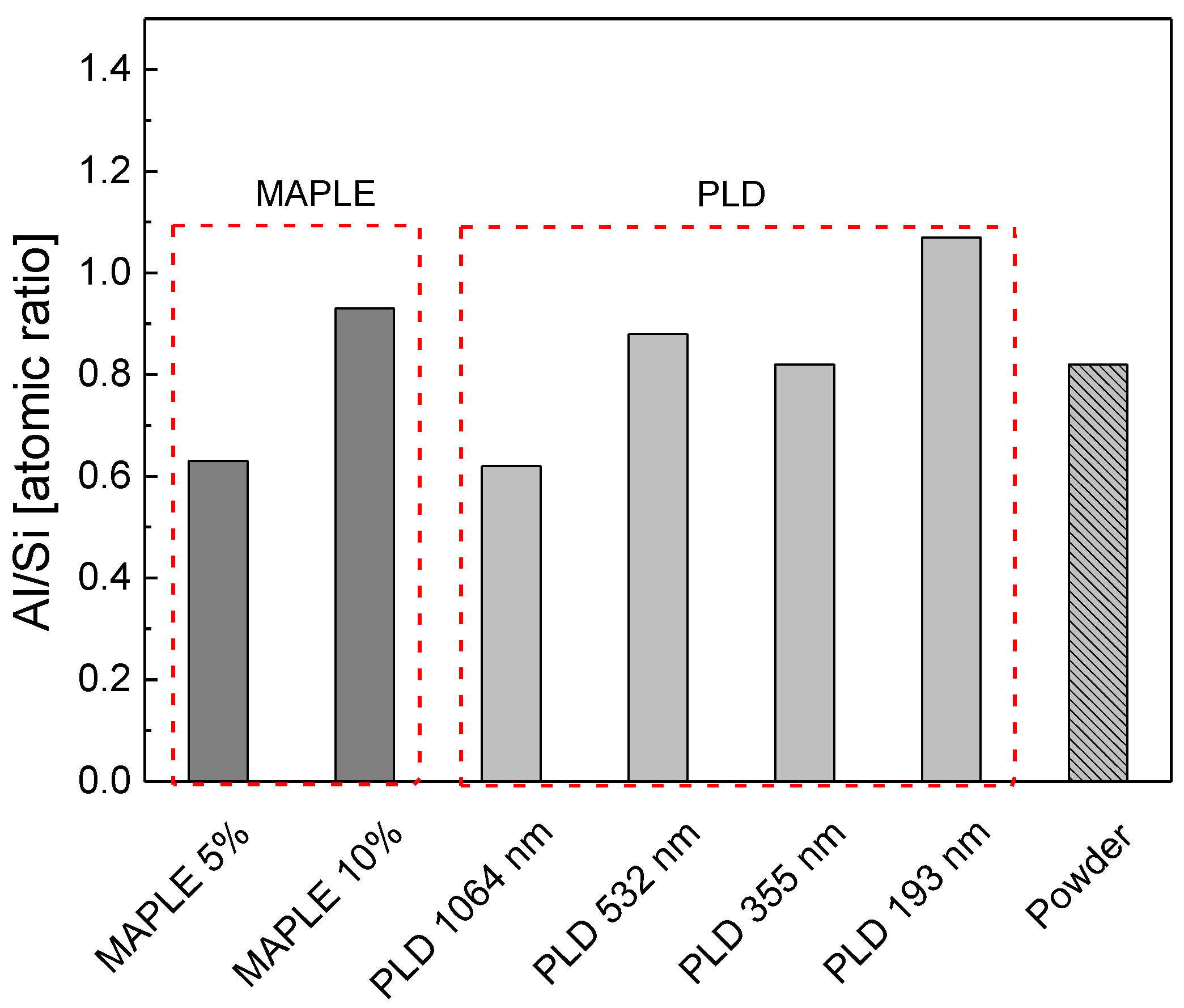
| Atomic % | MAPLE 5% | MAPLE 10% | PLD 1064 nm | PLD 532 nm | PLD 335 nm | PLD 193 nm |
|---|---|---|---|---|---|---|
| O1s | 66.22 | 65.33 | 62.79 | 60.92 | 62.63 | 63.06 |
| Si2p | 20.73 | 17.95 | 22.97 | 20.69 | 20.51 | 17.80 |
| Al2p | 13.05 | 16.71 | 14.24 | 18.39 | 16.85 | 19.13 |
| Al/Si | 0.63 | 0.93 | 0.62 | 0.88 | 0.82 | 1.07 |
Publisher’s Note: MDPI stays neutral with regard to jurisdictional claims in published maps and institutional affiliations. |
© 2022 by the authors. Licensee MDPI, Basel, Switzerland. This article is an open access article distributed under the terms and conditions of the Creative Commons Attribution (CC BY) license (https://creativecommons.org/licenses/by/4.0/).
Share and Cite
Dumitrescu, L.N.; Ionita, E.-R.; Birjega, R.; Lazea-Stoyanova, A.; Ionita, M.-D.; Epurescu, G.; Banici, A.-M.; Brajnicov, S.; Andrei, F.; Matei, A. Kaolinite Thin Films Grown by Pulsed Laser Deposition and Matrix Assisted Pulsed Laser Evaporation. Nanomaterials 2022, 12, 546. https://doi.org/10.3390/nano12030546
Dumitrescu LN, Ionita E-R, Birjega R, Lazea-Stoyanova A, Ionita M-D, Epurescu G, Banici A-M, Brajnicov S, Andrei F, Matei A. Kaolinite Thin Films Grown by Pulsed Laser Deposition and Matrix Assisted Pulsed Laser Evaporation. Nanomaterials. 2022; 12(3):546. https://doi.org/10.3390/nano12030546
Chicago/Turabian StyleDumitrescu, Luminita Nicoleta, Eusebiu-Rosini Ionita, Ruxandra Birjega, Andrada Lazea-Stoyanova, Maria-Daniela Ionita, George Epurescu, Ana-Maria Banici, Simona Brajnicov, Florin Andrei, and Andreea Matei. 2022. "Kaolinite Thin Films Grown by Pulsed Laser Deposition and Matrix Assisted Pulsed Laser Evaporation" Nanomaterials 12, no. 3: 546. https://doi.org/10.3390/nano12030546
APA StyleDumitrescu, L. N., Ionita, E.-R., Birjega, R., Lazea-Stoyanova, A., Ionita, M.-D., Epurescu, G., Banici, A.-M., Brajnicov, S., Andrei, F., & Matei, A. (2022). Kaolinite Thin Films Grown by Pulsed Laser Deposition and Matrix Assisted Pulsed Laser Evaporation. Nanomaterials, 12(3), 546. https://doi.org/10.3390/nano12030546