1. Introduction
Since the end of the 2008 financial crisis, competitiveness, industry and innovation promotion have taken centre stage in the transformation of all socioeconomic activities and, more specifically, those related to the engineering and public works sector [
1,
2]. In 2019, the European Commission implemented the Green Deal, a major agreement whose aim is to make the continent climate-neutral by 2050 [
3]. This ambitious goal can only be reached using a real economic transformation, based on the innovation, digitalization and reindustrialization of the entire continent, as a catalyst [
4]. Moreover, after a devastating pandemic year, in December 2020 the European Union defined a new multiannual financial framework, with a long-term budget of 1.8 billion Euros, including a temporary recovery instrument called Next Generation EU. This agreement aims at reinforcing specific programmes to mitigate the economic and social impact of the COVID-19 pandemic and make European economies and societies more sustainable, resilient and better prepared for the challenges and opportunities of the green and digital transitions [
5].
The underground work industry is aware of all these policies aimed at promoting innovation and sustainability and has been moving in this direction for years [
6]. The tunnel boring industry blossomed during the 19th century, with the development of the railway. During the 20th century, there were major advances in the understanding of ground response mechanisms as well as support design methods [
7]. In the 70s, tunnelling technology experienced a qualitative leap, with the introduction of the tunnel boring machines (TBMs), which could install one type of support automatically by means of precast concrete segments as the boring was taking place. Nowadays, both tunnel boring machines and the machinery that is necessary to bore tunnels under the New Austrian Tunnelling Method (NATM) include a large number of sensors and technology that enable carrying out underground work under safe conditions and with performances that were unthinkable just a few years ago [
8].
At present, there are different technological innovation lines in the world of underground work, the most noteworthy of which are the following: implementation of specific tunnel information systems, sophistication of the numerical methods used in the design of underground structures and ability to feed them with real data, use of virtual reality to view aspects of the design of underground works, use of sensors and machine learning to optimize the collection of data associated to the construction process, consideration of the environmental impact of tunnelling as well as the materials used, increase in the efficiency of road headers and machinery associated with the construction process or development of robotic inspection at all stages of the project [
8,
9,
10].
This article shows various innovation initiatives related to those indicated above, within a specific underground work, the construction of the Arnotegi tunnels, as part of the extension of the south bypass of the city of Bilbao, in the north of Spain. These innovation activities have been combined in a single underground work, of which no previous references in road tunnels have been found, and have led to time and therefore economic savings compared to the initial forecast.
2. Case Study: The Arnotegi Tunnel in Bilbao South Metropolitan Bypass
The construction of the Arnotegi tunnel (
Figure 1) is part of the works of the so-called 9a Section of the infrastructure of Bilbao South Metropolitan Bypass (VSM, for its acronym in Spanish). This bypass was devised within the Special Accessibility Plan Bizkaia 2003. The aim is to give continuity to the bypass that supplements the A8 highway, which is now reaching the limit of its capacity.
The site is situated in the municipality of Bilbao, just south of the city centre. To be precise, Section 9a starts at Peñascal Junction, inside the cut-and-cover tunnel which has already been constructed under the area where the vehicles that leave the South Metropolitan Bypass towards the A-8 highway through the Larraskitu tunnels have to pay the toll. From this cut-and-cover tunnel, it continues along the Arnotegi tunnel, the main feature within this section, as far as the Bolintxu valley. The Arnotegi tunnel is a twin tunnel, with a tube in each direction. The tunnel corresponding to the lane in the direction of Cantabria (Axis 1) is 1727 m long, whereas the tunnel excavated for the lane in the direction of Donostia (Axis 2) is 1722 m long.
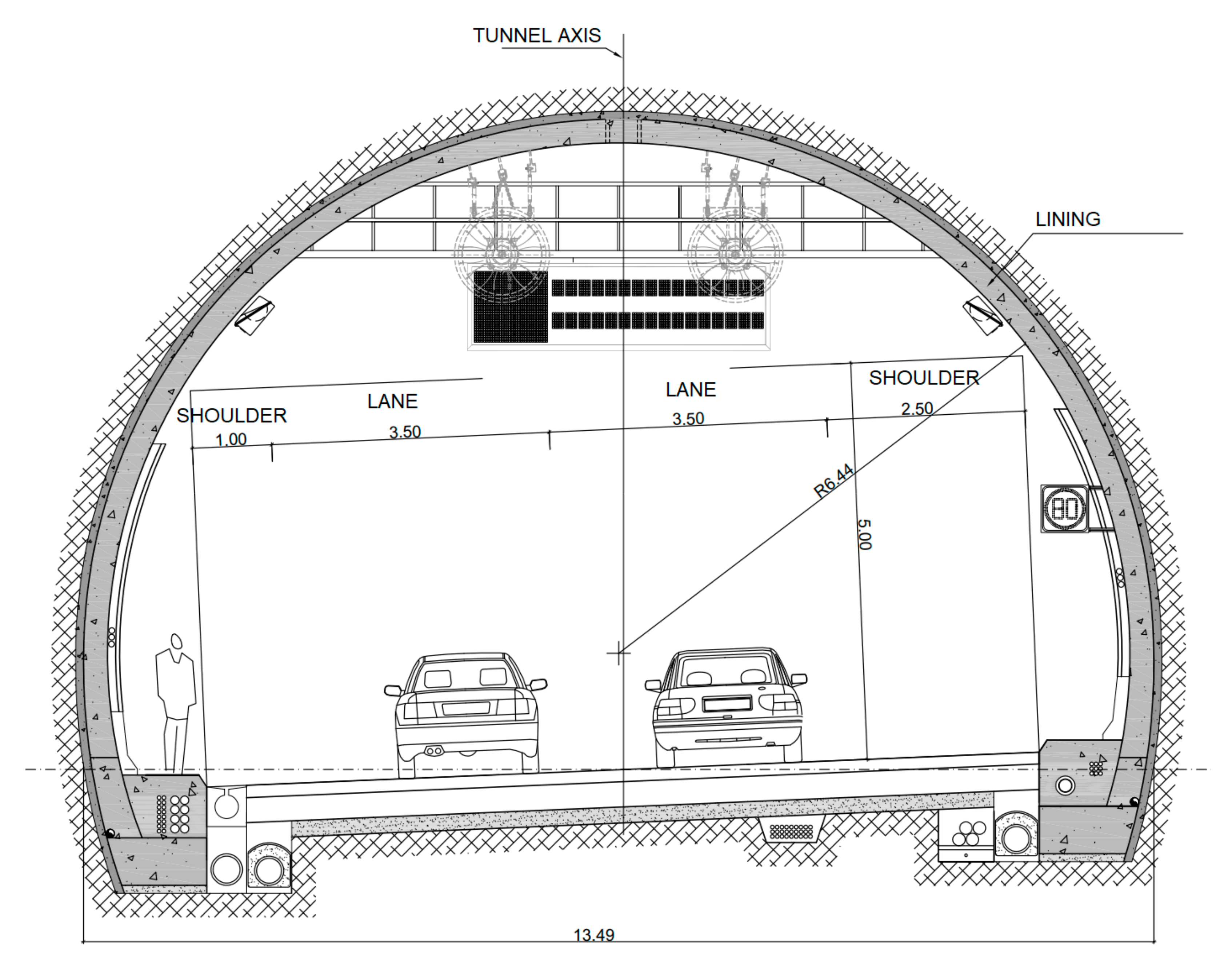
The tunnel has a truncated circular cross-section, and an inner section of 85 m
2 (
Figure 2). Its main characteristics are shown in
Table 1.
From the geological point of view, the Arnotegi tunnel runs through rocky terrain dating from the Cretaceous Period, made up of siltstone with sandstone levels. The average values of the parameters of this lithotype are shown in
Table 2.
The tunnel was excavated from the entrance portal at Peñascal Junction, using the New Austrian Method (with drilling and systematic blasting, except in particular cases, such as gallery intersections, where mechanical excavation was used). According to the geotechnical characteristics of the excavated materials, the project involves five types of support, estimated using Barton’s abacus or Q-system [
11]. Moreover, each type of support (
Table 3) is applied to specific conditions as defined by Bieniawski’s geomechanics classification or RMR system [
12].
The frequency of appearance of each type of support in the Arnotegi tunnel is shown in
Figure 3. All the support types have been verified by performing fracture and block stability calculations and up to 9 stress-strain calculations using the finite element method, both in two and three dimensions.
Eight vehicle interconnection galleries were constructed along the Arnotegi tunnel. They all have a vaulted ceiling and straight side walls, an inner section of 17 m2, vertical clearance of 3.50 m and platform width of 3.95 m.
The tunnel has collectors and drains for seepage as well as run-off water, fire protection, communications and power ducts, sidewalks, barriers, roadbed and singular elements, such as flow control and pressure control boxes as well as auscultation systems (
Figure 4). A complete ventilation and lighting system is also included, in accordance with national reference standards. The main lighting system of the tunnel consists of a longitudinal line of LED luminaires. Additionally, the tunnel complies with the standards of the provincial decree on road tunnel safety [
13,
14].
A series of instrumentation elements were installed along the tunnel, both to control its execution and also to monitor its evolution during the operation and maintenance phase. A total of 102 extensometers, 102 radial cells and 102 tangential cells were installed inside the tunnel. In addition, 20 load cells for anchor monitoring were installed in the external tunnel.
Safety and efficiency in the construction of the tunnel have been increased by means of the following combined strategies:
Implementation of BIM methodology, understood as the preparation and development of coordinated and collaborative databases and information models, during the project execution stage as well as subsequent stages of the life cycle of the asset.
Environmental parameter control by means of specific sensors.
Optimization of shotcrete placement using laser scanning.
Development of a system for positioning machinery inside de tunnel.
These innovation strategies will be described in the sections below.
3. Innovation Strategies
3.1. Implementation of BIM Methodology in Underground Work
Underground work usually involves structures with complex geometries, often of great length. The use of digital design methods has great advantages as compared to 2D design, both for projects to be better understood by all the parties involved as well as for collision detection. BIM methodology has a specific application in this field and some international organizations have even published the first recommendations to deal with this methodology in underground construction [
15].
The aim is to obtain a BIM model of the Arnotegi tunnel that comprises all relevant tunnel construction elements, including both graphic as well as non-graphic information, and facilitates coordination with subsequent works and with the exploitation and maintenance of the infrastructure.
Three main models are developed: an initial model, an updated model and a follow-up model, which is updated throughout the work after each pass. The main uses of the initial model, based on the first 2D project, are the 3D design and the detection of interferences. The main uses of the updated model (
Figure 5) are the coordination of the 3D design, the resolution of discrepancies and acting as the basis for the subsequent facilities project.
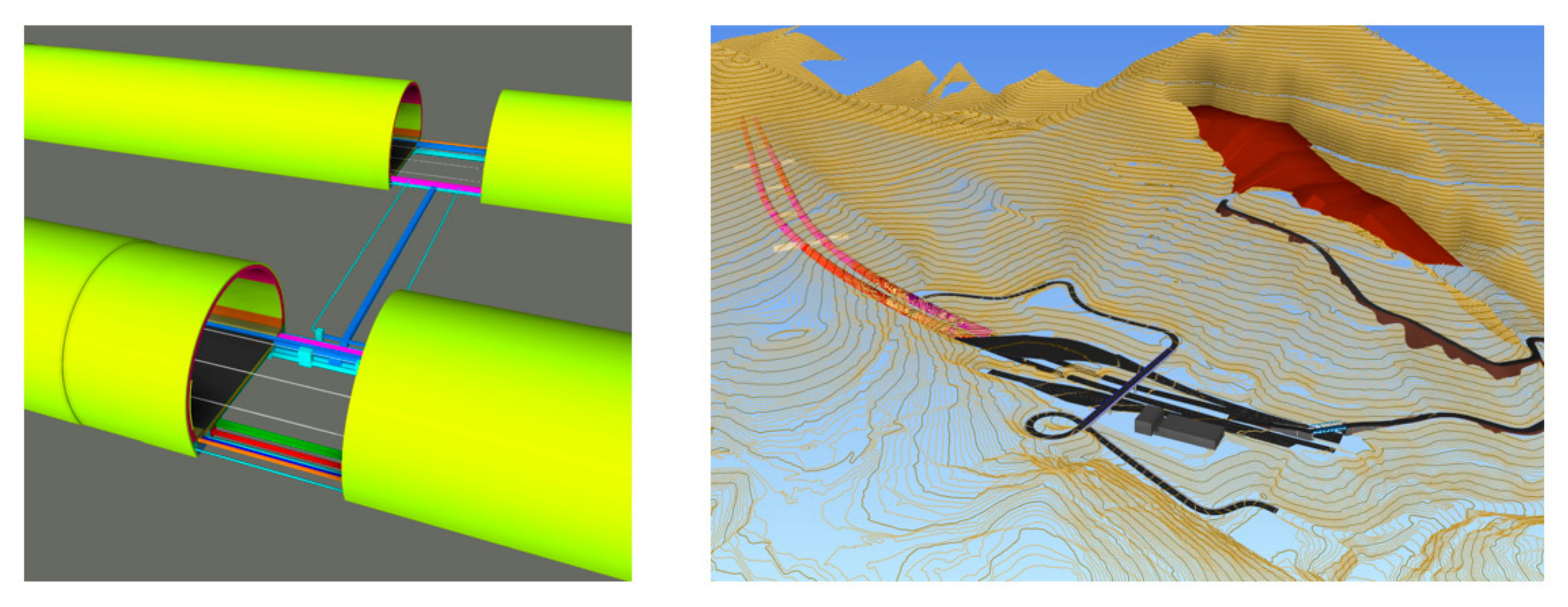
The main uses of the follow-up model (
Figure 6) are the execution of the project as-built as the work progresses, its geometric control (tolerance in each pass, section entry…), the integration of the information generated during the construction process (front surveys, material quality certificates, photographs) and the integration of new control geometries (special treatments or sensors, in the case of sections with V-type support). The main novelty in the project with respect to the use of BIM methodology has been the generation of an updated model after each pass, with an average of one model per day during the whole execution of the tunnel.
Once the file structure of the common data environment has been defined, it is time to define the elements that make it up. On the one hand, there are a number of digital models from the different disciplines that are associated in a coordination model for revision and modification, where appropriate, and, on the other hand, all the non-modelled information that is generated at the different stages of the construction project and can be linked to the various modelled elements and stored within the common data environment. All this centralized information (modelled as well as non-modelled) enables monitoring the work in an integrated and efficient manner.
The work chart proposed to define the collaborative work flow in the application of the BIM methodology in the Arnotegi tunnel is shown in
Figure 7. This figure shows how the BIM model, the non-modelled information and the monitoring work are centralized in a common database to be interacted with through the common data environment.
The global management of the project is carried out using Vircore software [
16], developed by Ingecid S.L. A hierarchical role system is defined to enable the collaboration of the various agents involved in the project. This way, it is possible to control users’ access to the tasks they have been assigned by means of a simple authorization system (for example, the project manager can access all the information from the common environment, but the quality, environment or prevention managers can only access the files corresponding to their areas of responsibility).
3.2. Increasingly Important Role of the Environmental Variable: Use of Environmental Sensors
Specific environmental monitoring of the work is carried out using an environmental sensor system, able to measure the main water, air and noise emission parameters and send the data to a cloud, which can be accessed by any authorized mobile device previously defined in the role system (
Figure 8).
Water quality control focuses on temperature, pH, dissolved oxygen, redox (or oxidation-reduction chemical reactions), conductivity and turbidity. There are two points with time control situated near the discharge points previously defined in the specifications of the construction project.
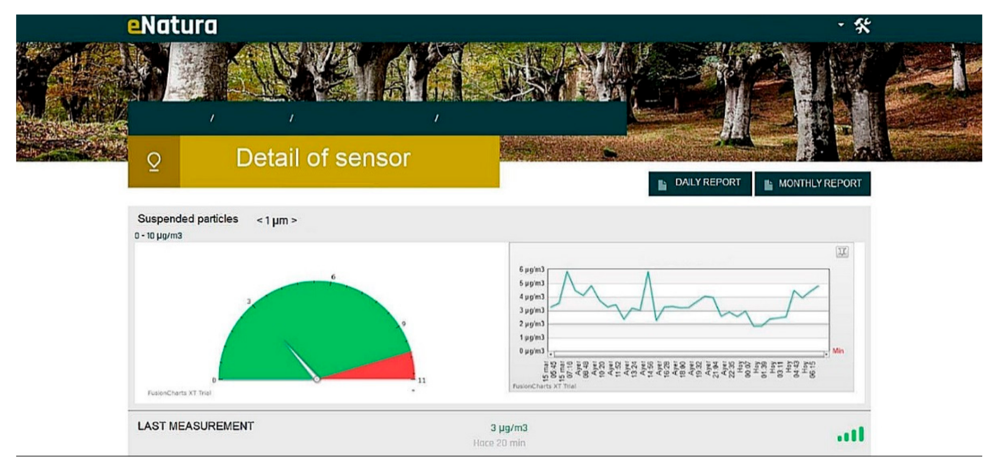
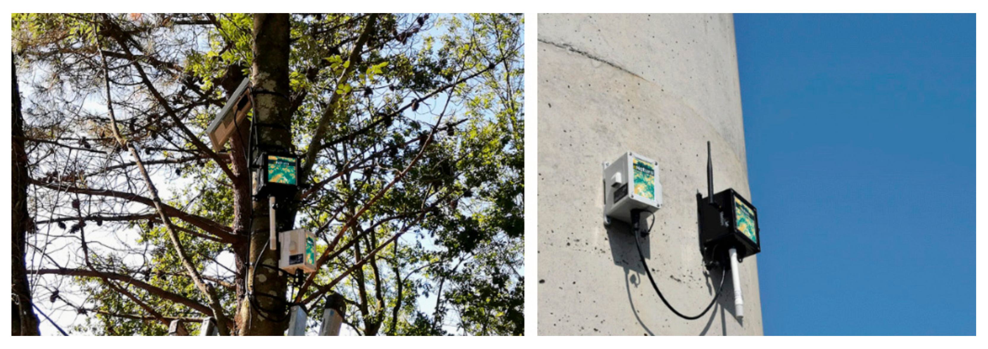
Air quality control measures 4 parameters every 45 min: suspended particles, temperature, pressure and humidity. There are two control points, one next to the working face and another one situated on the access road to the Bolintxu portal (
Figure 9). The air and water measuring results are entered into the eNatura platform [
17], developed by Fulcrum S.A.
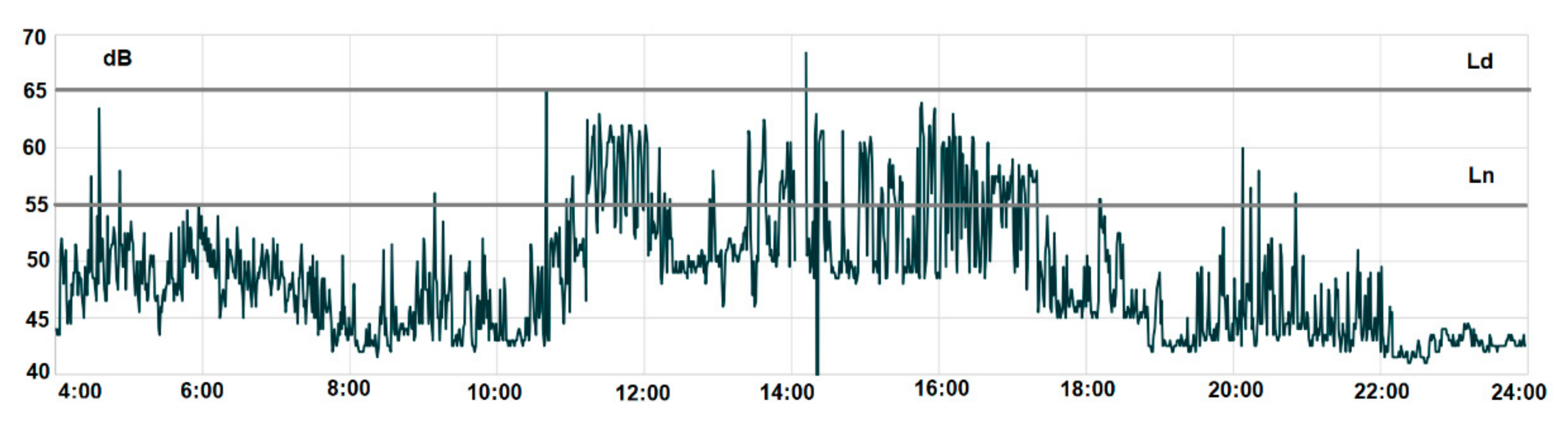
As for noise control, there is an integrating sound level meter that assesses environmental noise quality. This continuous assessment is necessary due to the noise variability that is going to take place during the works, either as a result of the drilling work or the traffic of heavy vehicles as well as the closeness of some homes to the front of the tunnel.
Noise maps were prepared during the initial stage using CadnaA software [
18], which complies with the requirements provided in Directive 2020/49/EC [
19] as well as Act 13/2003 on Noise [
20]. The methodology used is based on the French method for road noise prediction NMPB Routes-96 [
21], in such a way it is possible to obtain noise scenes before the start of the works (
Figure 10).
Once these analyses have been performed, it is time to identify the sensitive zones in the affected area and implement corrective measures, such as the installation of a closing door at the entrance of the tunnels to reduce the airwave. The so-called acoustic quality objectives (AQO) for the residential areas are then established, with thresholds of 65 dBA during the day at the facade (Ld) and 55 dBA at night (Ln). The continuous recording with the sound meter along the construction work enabled checking these acoustic quality objectives (
Figure 11).
The reports from these environmental sensors have been linked to the aforementioned common data environment. This data recording enabled compliance with the environmental quality levels established in the specifications and, occasionally, in case the sensors were alarmed, the deployment of specific corrective measures (in the case of noise levels, for example, the readjustment of some earthmoving activities at the entrances during the night due to the fact that they could have exceeded the threshold established in the acoustic quality objective). The common data environment also allowed access to the real-time databases of the load and displacement sensors installed along the tunnel.
3.3. Optimization of the Shotcrete Placement Process
Nowadays, success when placing the shotcrete depends to a large extent on the workers who operate the gunning robots, who must have extensive experience in this type of task, so as to achieve the thickness prescribed in the project specifications and avoid or minimize bouncing and rejection, which are the most critical aspects of the process (
Figure 12).
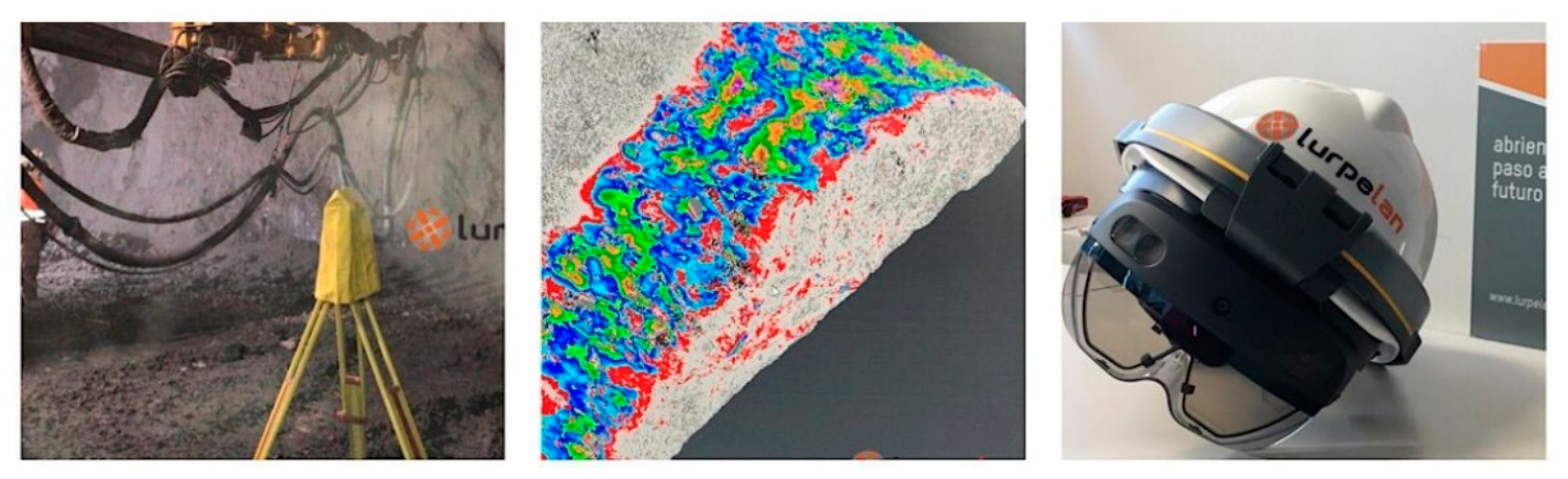
At the Arnotegi tunnel, the aim was to optimise the concrete shooting process by means of a combination of different advanced technologies whose technological core lies in the implementation of 3D digital scanning techniques during the shooting process, fed with process enhancement algorithms, which are connected with the BIM model of the tunnel. These activities were carried out within the “SHOTCRETE” research project, which consists in generating a data platform so as to automate the gunning process in underground works.
The initial information of the theoretical model (geometries, spatial relations, geographical information, properties of the components) is the basis used by the platform to carry out decision-making and inform the gunning machine operator about the progress of the activity, indicating the areas where the prescribed thickness has been reached and those where it is necessary to shoot more concrete. The gunning process is carried out in three different stages, between which intermediate scanning is carried out in order to generate process status information. This information can be transferred to the machine operator by means of a tablet or virtual reality glasses.
Finally, once the gunning has been completed, the integrated laser-scanner technology collects information from the gunned surface using a point cloud and the information is updated in both the data platform of the SHOTCRETE project as well as the BIM model of the tunnel (
Figure 13).
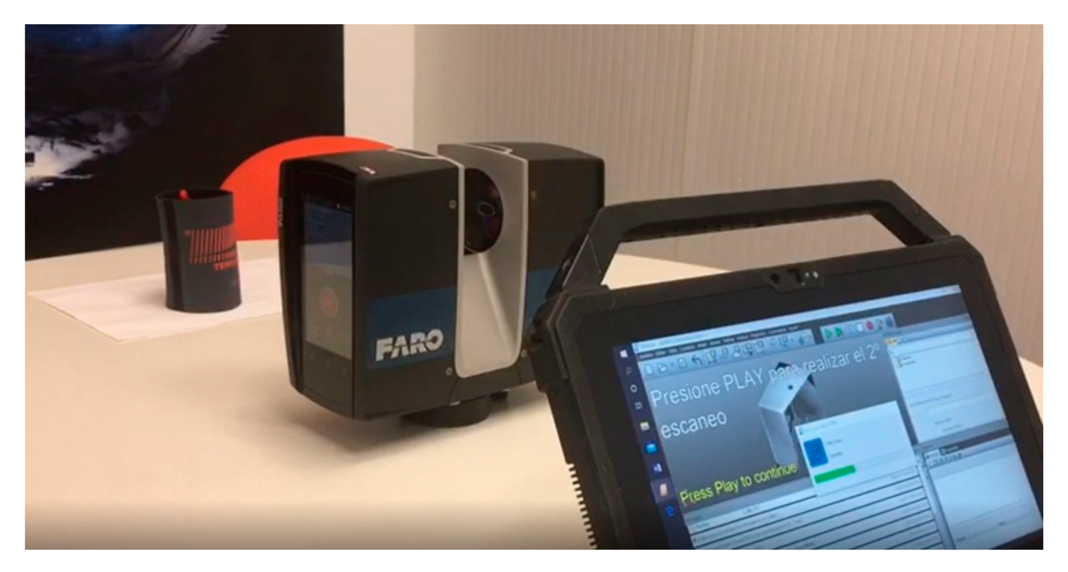
The laser-scanner used is a high-speed 3D laser-scanner. It uses infrared laser technology to produce extremely detailed 3D images of the surrounding environment and complex geometries in few seconds. To measure distances, it uses phase shift technology, in which constant waves of infrared light of varying lengths are projected outward from the scanner. In the environment where it was used, it has an accuracy of 1 mm (
Figure 14).
The main challenge during the execution of the tunnel is the difficulty to scan in dusty environments, which prevents the non-stop performance of the process. Despite the stops to carry out interim verification scanning, which lasts between 2 and 3 min, the global efficacy of the process improves considerably, since the error rate in the target shotcrete placement almost disappears and the ensuing rectification or reinforcement operations which usually slow down and hinder the subsequent tunnel lining activities are no longer necessary.
3.4. New System for Positioning Machinery Inside the Tunnel
In addition to the optimization of the shotcrete placement process, a system for positioning machinery inside the tunnel was developed to help backhoe operators in the reprofiling limits of each section.
The geometry of the section is verified after each blast. If there is an area where the blast has not removed sufficient material, it is necessary to go over it again with a hydraulic breaker, interrupting the normal tunnel construction cycle. This rectification must be exactly as required, since excavating more than necessary will involve additional costs in both shotcrete as well as facing concrete. This is the reason why it is essential to place the hydraulic breaker in the exact point and know exactly the depth to which it must reprofile.
The 3D machinery positioning technology is already quite advanced as far as external works are concerned and has synergies with the usual grading software. However, the usual use inside the tunnel is not possible; therefore, it has been necessary to locate the backhoes with robotic stations able to determine their position inside the tunnel in real time. Once the machine has been located, it is possible to locate the top of the hammer with the movement sensors in its mechanical parts and display the information on the screen of the machine operator, in order to optimize the times and the profiling accuracy (
Figure 15).
4. Conclusions
This article describes the innovative practices that have been implemented in a pioneering manner in the context of a specific underground work, the construction of the Arnotegi tunnel within Bilbao South Metropolitan Bypass, as an example of the change of paradigm in the world of underground work.
The implementation of the BIM methodology enables monitoring the work in an integrated and efficient manner.
The control of the environmental parameters enables knowing the sensitive areas or the areas affected by the work and implementing corrective measures, thus decreasing or eliminating the environmental impact of the work.
The optimization of shotcrete placement using laser enables making decisions on site, by providing the gunning machine operator with an activity progress report, thus preventing subsequent rectification and reinforcement operations.
The development of a system for positioning machinery inside the tunnel enables optimizing hammering times.
Finally, it is necessary to mention that the implementation of these innovative practices has improved communication among all agents. Moreover, it has enabled the optimization of performance rates, due to which it has been possible to construct the tunnel 2 months before the initially planned deadline (6.60% improvement with respect to the total time). This saving factor is consistent with the values reported in the peer-reviewed literature [
22,
23].
All these innovative practices described in the article can be incorporated into most underground works. A successful implementation depends on the establishment of an appropriate contractual model so that all stakeholders can share information in a confident and transparent manner.

 ,
, 


