1. Introduction
Aeroelastic analysis of a modern wing with high flexibility is crucial. The ability to control the aeroelastic instability due to high flexibility is very important to achieve the desired aerodynamic performance in a wing design [
1,
2]. One important aeroelastic analysis is flutter resulting from the merging of two or more vibration modes during flight. The flutter phenomenon can reduce the flight envelope or require a redesign of the wing. Appearing flutter can compromise the long-term durability of the wing structure and the flight performance, operational safety, and energy efficiency of the aircraft. Hence, preventing flutter is crucial for the modern airplane [
3,
4,
5,
6,
7].
Smart materials have been used in wing structures for many years. Although there are different smart materials, piezoelectric materials have received the most attention. Considering the direct and inverse effects of piezoelectric materials, they can perform as sensors and/or actuators on a wing. In fact, they can be used as actuators and dampers to manage the aeroelastic behaviour of the wing. One effective way to avoid redesign the wing is to use piezoelectric materials to significantly delay the flutter [
8]. Piezoelectric actuators have been used in active aeroelastic control of an adaptive wing [
9]. They have also been implemented in honeycomb material for a flapping wing [
10]. In addition, optimal piezoelectric material has been used to control a plate subjected to time-dependent boundary moments and forcing function by vibration damping [
11]. Moreover, piezoelectric patches have been studied on passive flutter control of damaged composite laminates by employing the finite element method [
12]. Recently, piezoelectric layers have been used on thick porous plates to study the aeroelastic flutter [
13]. Furthermore, aeroelastic optimization has been investigated for materials with piezoelectric actuators and sensors [
14]. Adding a shunt circuit to a piezoelectric material can create a piezopatch to effectively modify the wing’s aeroelastic behaviour. Previously, there were practical limits in the low frequency range like the one typically existing in aeroelastic phenomena due to the large required inductance in passive aeroelastic control. However, it is now possible to have a small inductor integrated into a piezopatch dedicated to aeroelastic control [
15]. Since standard inductors usually have too much internal resistance for resonant shunt application, they are not a practical component to integrate into a piezopatch. Implementing closed magnetic circuits with high-permeability materials allows the design of large-inductance inductors with high quality factors.
The use of shunted piezopatch permits damping augmentation in the wing structure without causing any instability. In addition, they need little to no power and are simple to apply. Their necessary hardware includes the piezoelectrics and a simple electric circuit including a capacitor, inductor, and resistor. The shunted piezopatch can control aeroelastic vibration of the wing by consuming the energy created from wing vibrations. In fact, it can reduce the vibrations of specific modes and frequencies.
In this paper, the effect of piezoelectric material on increasing the flutter speed is investigated in detail by considering a simple aeroelastic system. The system is a 2D wing with a piezoelectric patch which has plunge, pitch, and control rotation degrees of freedom (DOF) as well as unsteady aerodynamic forces. The objective of this work is to represent the role of piezoelectric patches, which can substantially influence a simple aeropizoelastic system.
In
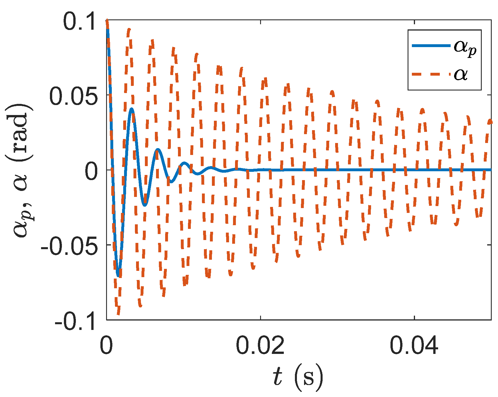
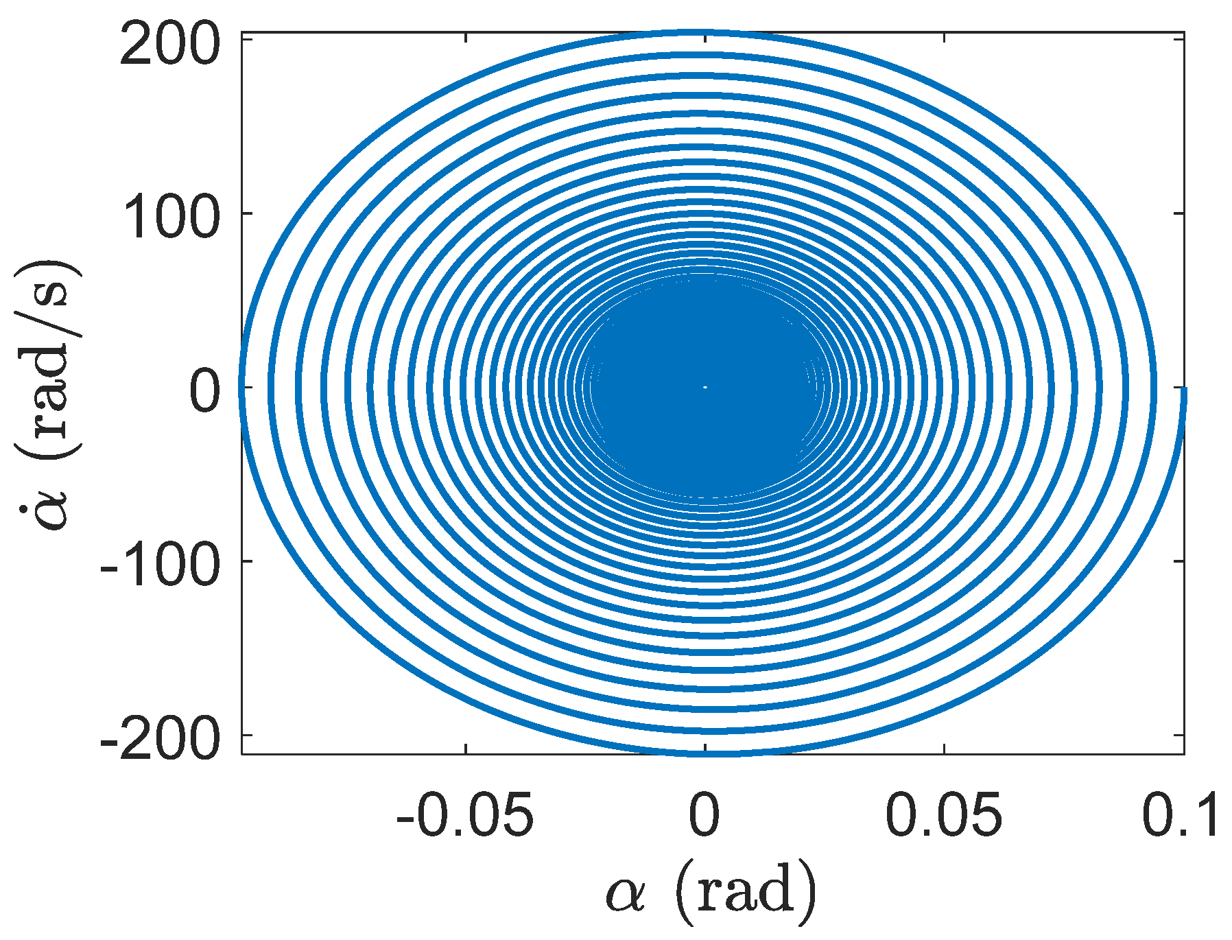
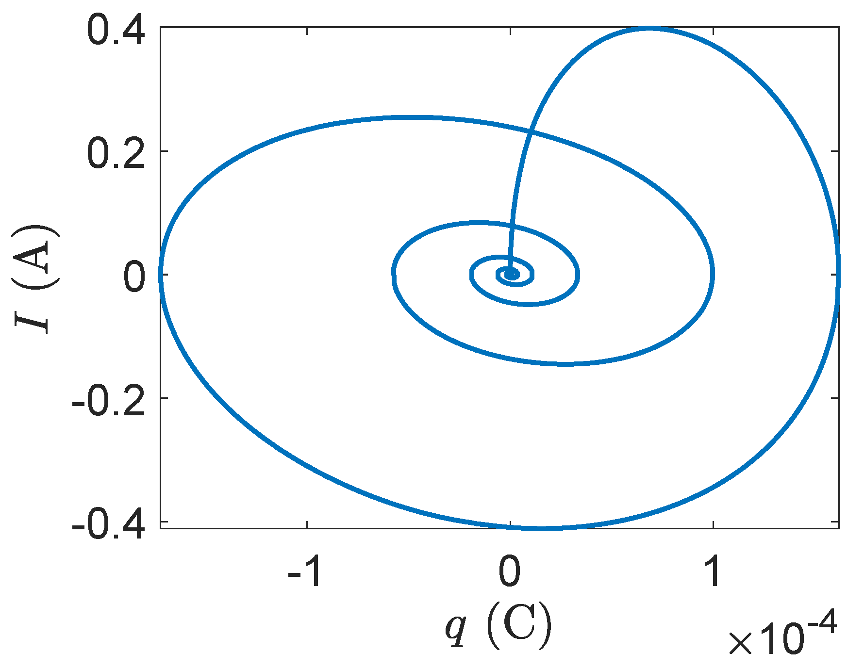
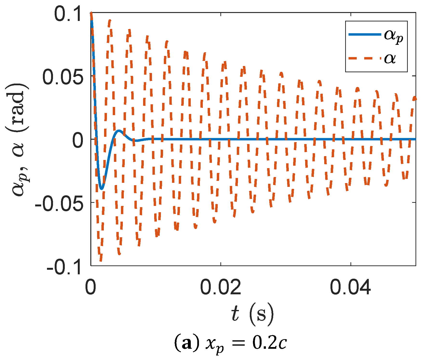
Section 2, the equations of motion of a smart wing with only plunge DOF are represented, and we explain how to solve those equations to obtain the plunge velocity, displacement, electrical current, and electric charge. Then, the fixed points of the system and its stability around those points are investigated to show the system response. Example 1 indicates the effective decay in the oscillation of a smart wing in comparison to a regular wing. In addition, a smart wing with only pitch DOF is presented to obtain its equations of motion in free vibrations. By solving the system of equations, the angular velocity, pitch angle, electrical current, and electric charge can be obtained. The stability of the system is then investigated around the fixed point. Example 2 indicates the system response of a smart wing with only pitch DOF and how effectively the oscillation can be decayed in a smart wing in comparison to that of a regular wing.
In
Section 3, a two-dimensional smart wing with the plunge, pitch, and control DOF and a piezopatch in the plunge DOF is represented to obtain the equations of motion under unsteady aerodynamic loads. Solving the system of equations produces the plunge velocity, displacement, electrical current, and electric charge as well as the pitching velocity, rotation, electrical current, and electric charge. Later, by finding the flutter speed, we show how adding one piezopatch can effectively postpone the flutter.
Section 4 represents a smart wing with the plunge, pitch, and control DOF and piezopatches in the plunge and pitch DOF. We show that the flutter speed can be further increased by having two piezopatches. Finally, in
Section 5, a smart wing with three DOF and three piezopatches in the plunge, pitch, and control DOF is presented to indicate how it can remove the flutter.
3. Two-Dimensional Unsteady Plunge–Pitch–Control Smart Wing
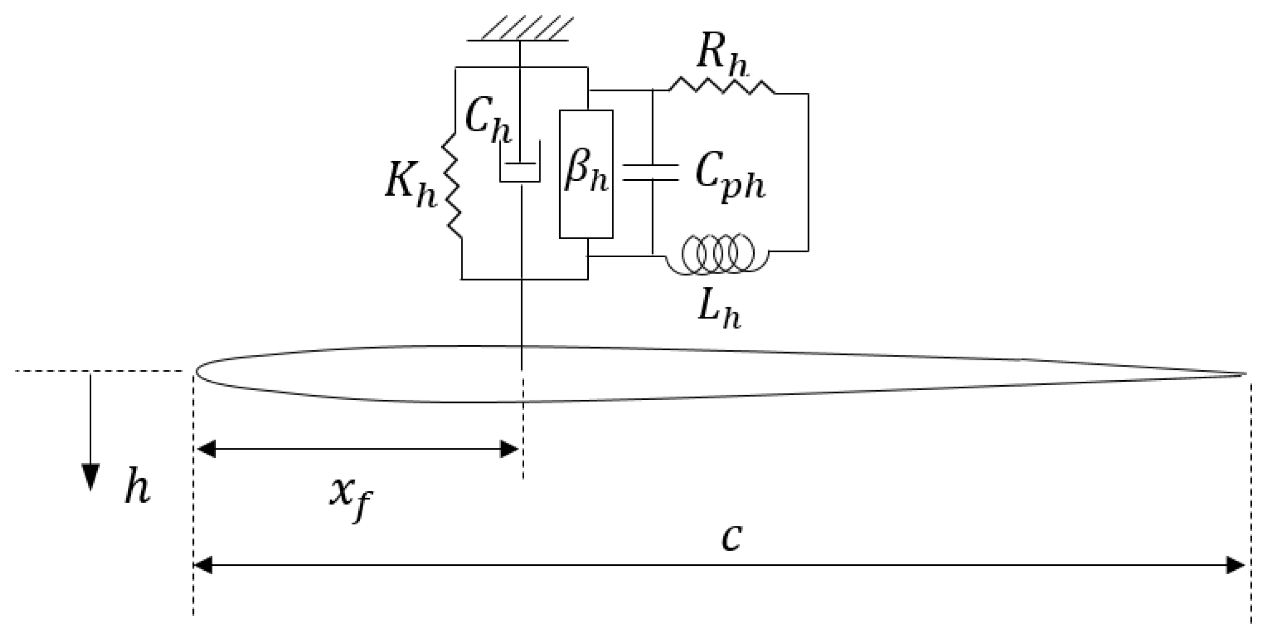
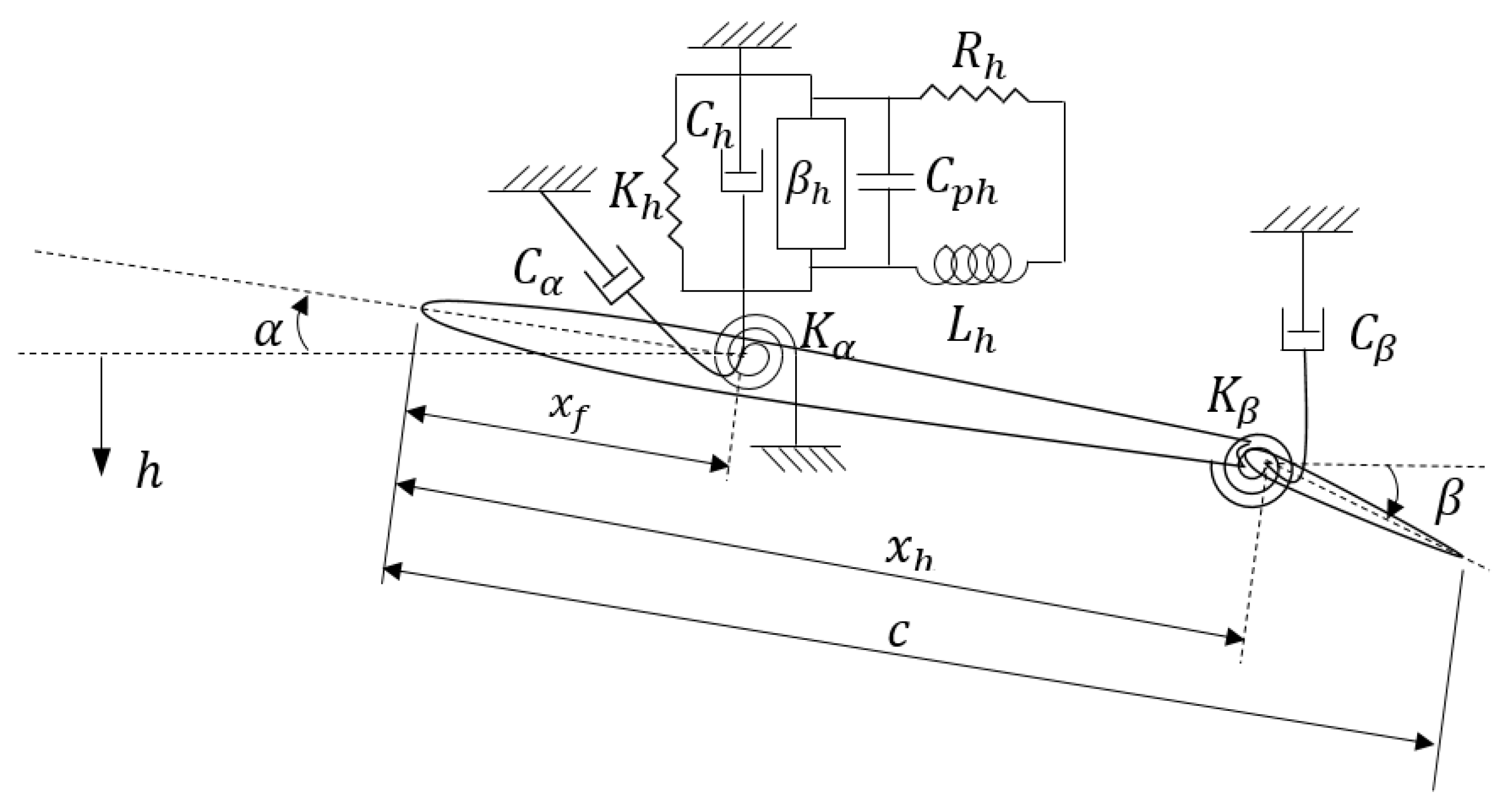
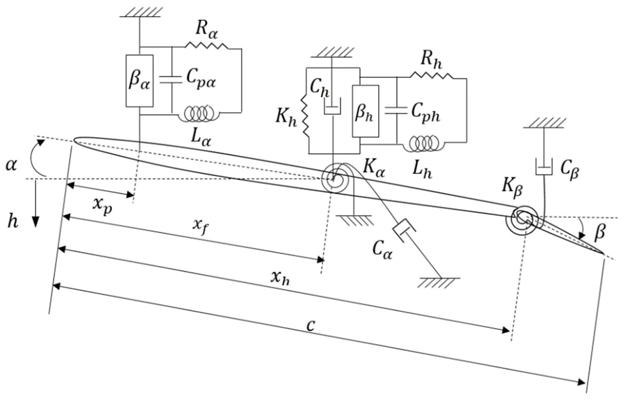
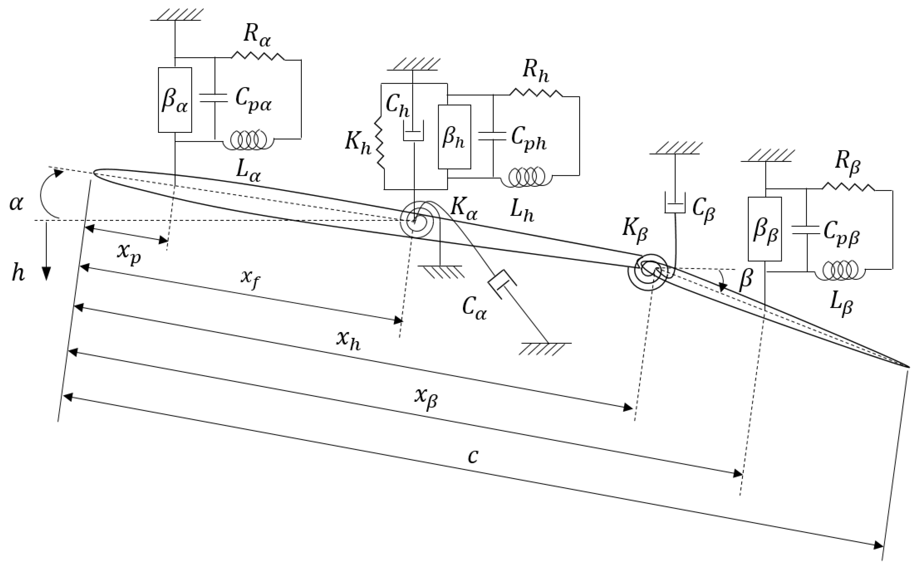
A linear 2D smart wing which has plunge, pitch, and control degrees of freedom is shown in
Figure 10. The model contains an airfoil with a piezoelectric patch in the plunge DOF, called piezo-plunge-wing. The system has the plunge, pitch, and control DOF indicated by
,
, and
, respectively. The DOF
represents the angle of the control surface around its hinge, located at distance
from the leading edge, and
denotes the stiffness of the control surface.
The equations of motion can be obtained by using the Lagrange’s equations and the Kirchhoff’s law as [
16,
17]
where
is the mass per unit length of the wing,
is the static mass moment of the wing around the pitch axis
,
is the mass moment of inertia around the pitch axis
,
is the static mass moment of the control surface around the hinge axis
,
is the control surface moment of inertia around the hinge axis,
is the product of inertia of the wing and control surface,
is the lift,
is the pitching moment of the wing around the pitch axis
,
is the pitching moment of the control surface around the hinge axis
,
is the plunge electromechanical coupling,
is the plunge capacitance of piezoelectric material,
is the plunge inductance of piezoelectric material,
is the plunge resistance of piezoelectric material, and
is the plunge electric charge. The electromechanical coupling,
, depends on the plunge coupling coefficient,
, and the plunge capacitance,
, and it can be calculated by
. Considering unsteady aerodynamics, the lift and moments can be written as follows [
18,
19]
Substituting Equations (19) to (21) into Equation (18) gives a set of equations of motion which is only time dependent and can be solved numerically by using the backward finite difference scheme for numerical integration [
19]. However, implementing the exponential form of the Wagner function’s approximation, the equations of motion can be rewritten as ordinary differential equations which can be solved analytically rather than numerically, which is much more practical [
20,
21]. The Wagner function’s approximation is as follows
where
,
,
, and
.
The full unsteady aeroelastic equations of motion can be written as
where
is the displacement and charge vector,
is the aerodynamic states vector,
is Wagner’s function,
is the structural mass and inductance matrix,
is the aerodynamic mass matrix,
is the structural stiffness and resistance matrix,
is the aerodynamic stiffness matrix,
is the aerodynamic state influence matrix,
is the initial condition excitation vector, and
and
are the aerodynamic state equation matrices.
Equation (23) can be written in purely first order ordinary differential equations form by
where
where
is the
state vector,
,
is a
unit matrix,
is a
matrix of zeros,
is a
matrix of zeros,
is a
matrix of zeros, and
is a
vector of zeros. The initial conditions are
. The initial condition
is an excitation whose effect decays exponentially. In order to obtain steady-state solutions, the initial condition is ignored in this paper; therefore, Equation (24) becomes
Example 3. A smart wing with plunge, pitch, and control DOF and a piezopatch in plunge DOF.
As the third example, a smart wing with plunge, pitch, and control DOF (
Figure 10) was considered with the following parameters [
16]:
,
,
,
,
,
,
,
,
,
,
,
,
,
,
, and
.
After running the simulation, the flutter speed was
which showed an
increase in the flutter speed of a regular wing with the same characteristics and without the piezoelectric patch.
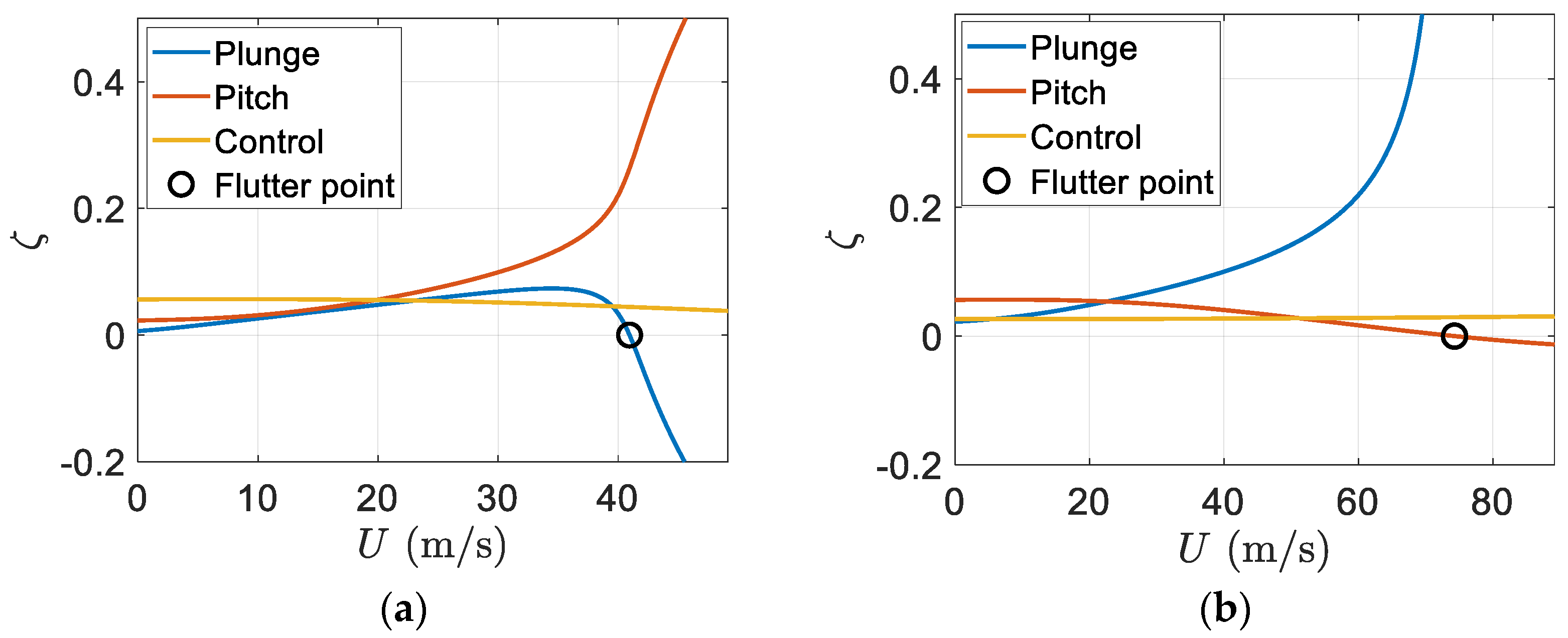
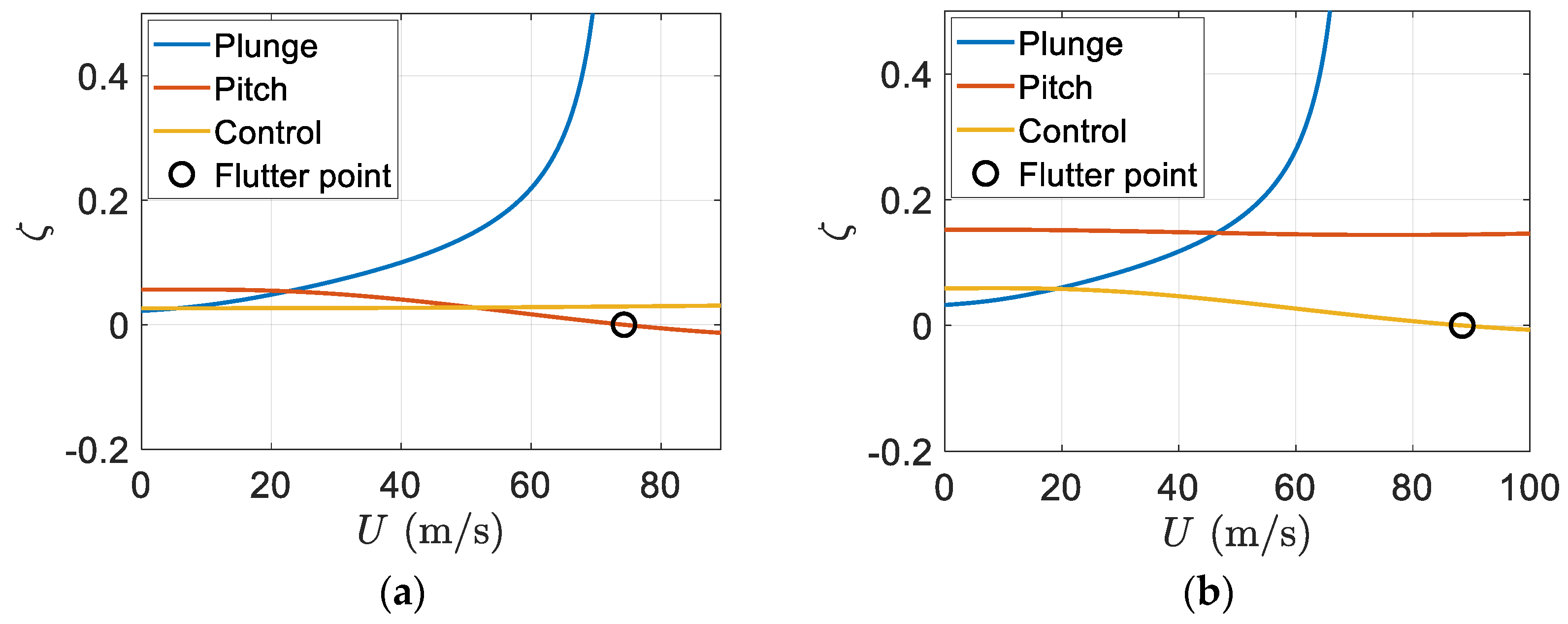
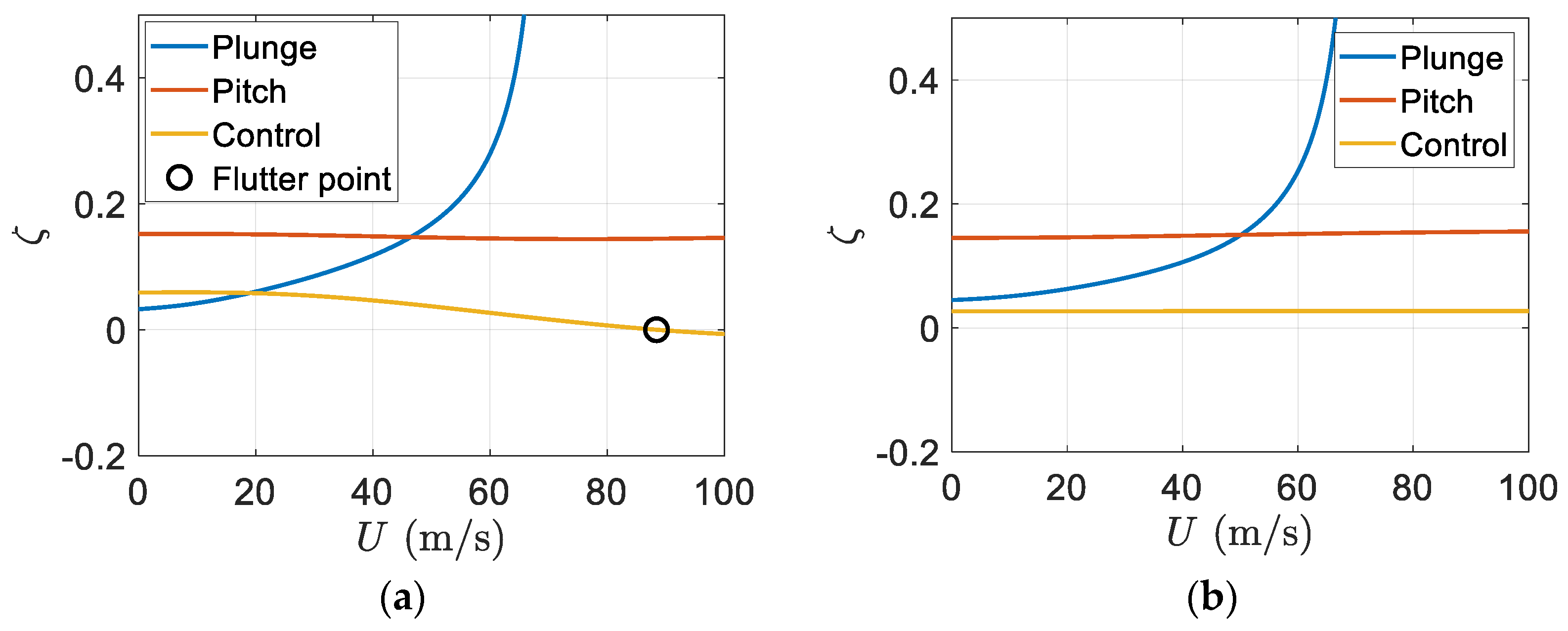
Figure 11 depicts the variation of damping ratios of a regular wing and smart wing with respect to the airflow velocity or airspeed. It can be seen that having a piezoelectric patch on the wing can effectively increase the flutter speed. Furthermore, due to the piezoelectric effect, there was no flutter in the plunge mode; however, flutter happens in the pitch mode, as shown in
Figure 11.
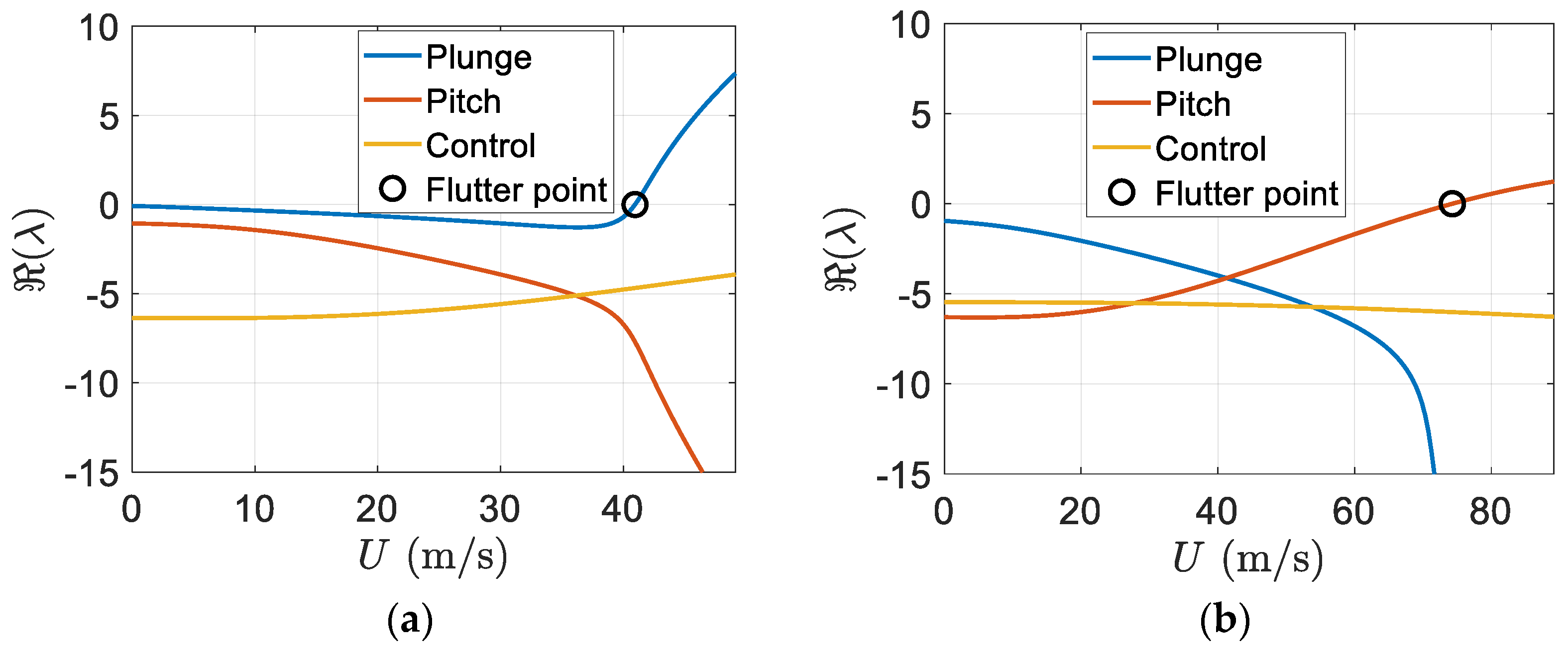
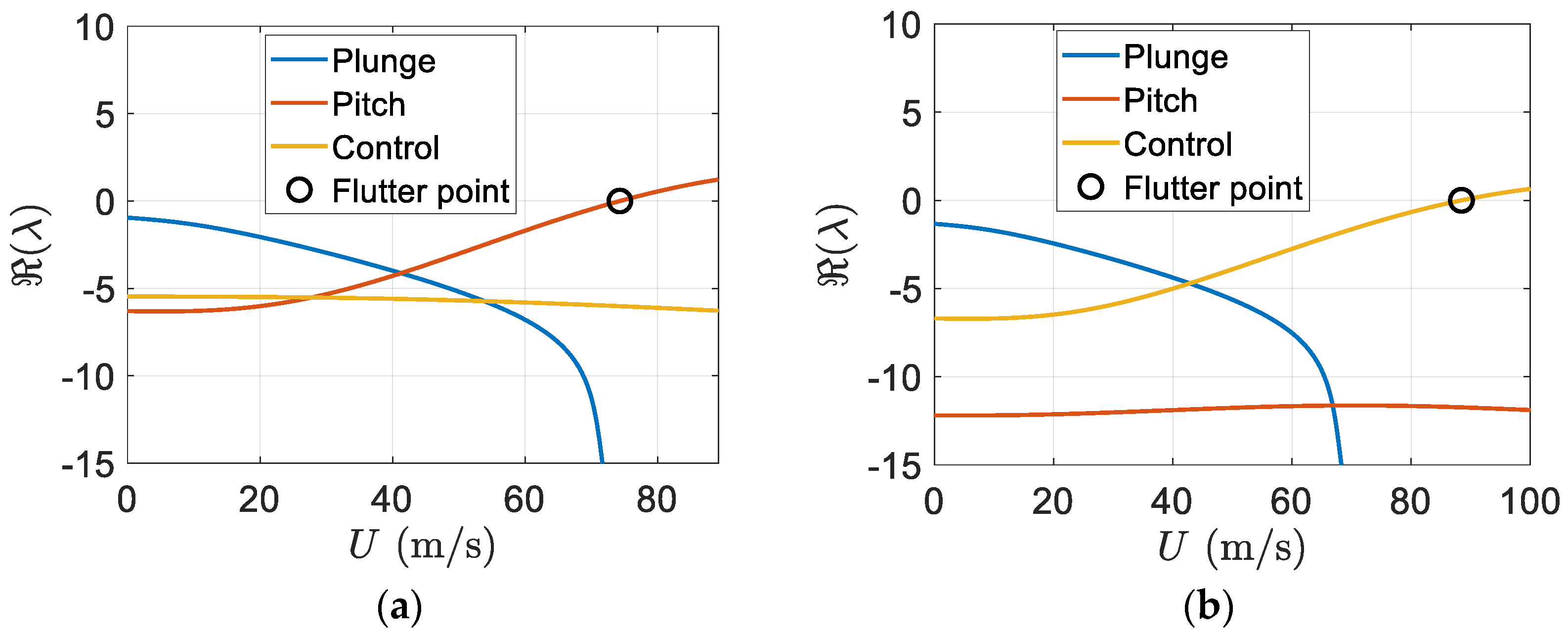
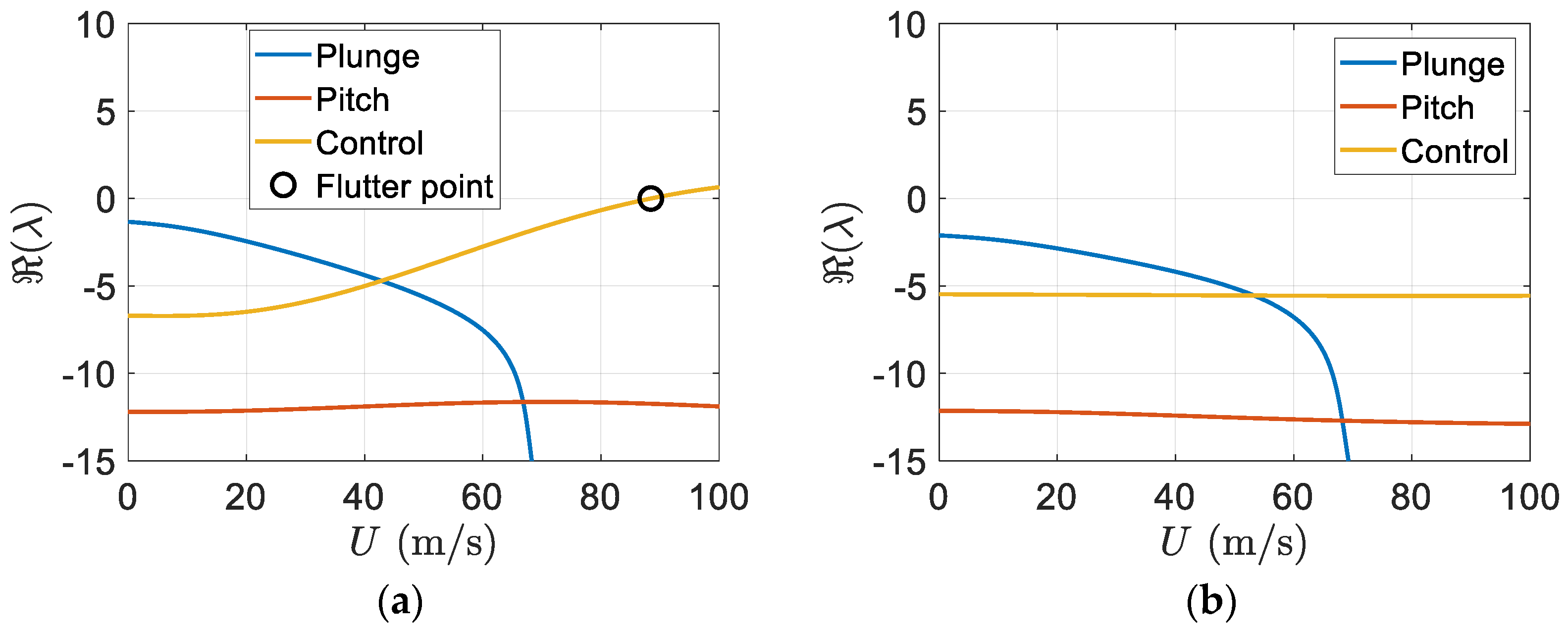
In addition, the real part of eigenvalues versus the freestream velocity is shown in
Figure 12. Again,
Figure 12b indicates flutter appears in the pitch mode. There is an effective increase in the flutter speed of the smart wing in comparison to the regular wing.
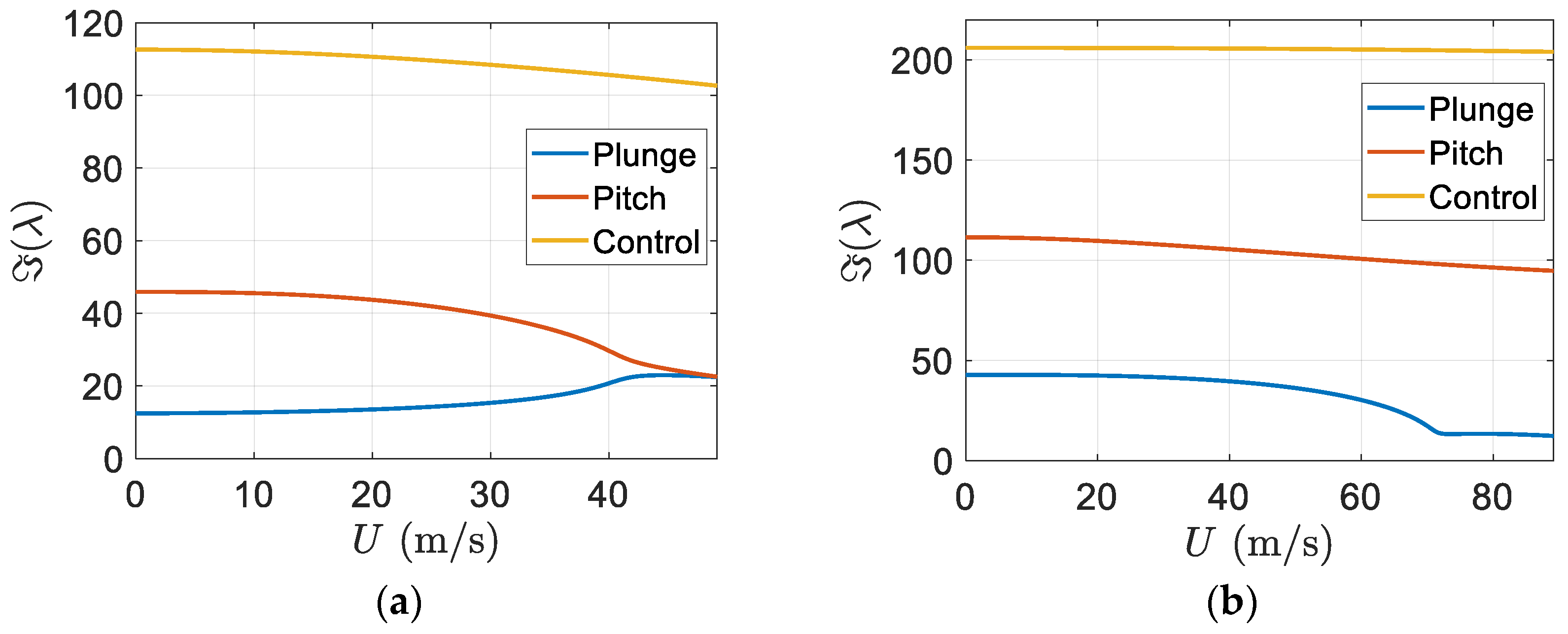
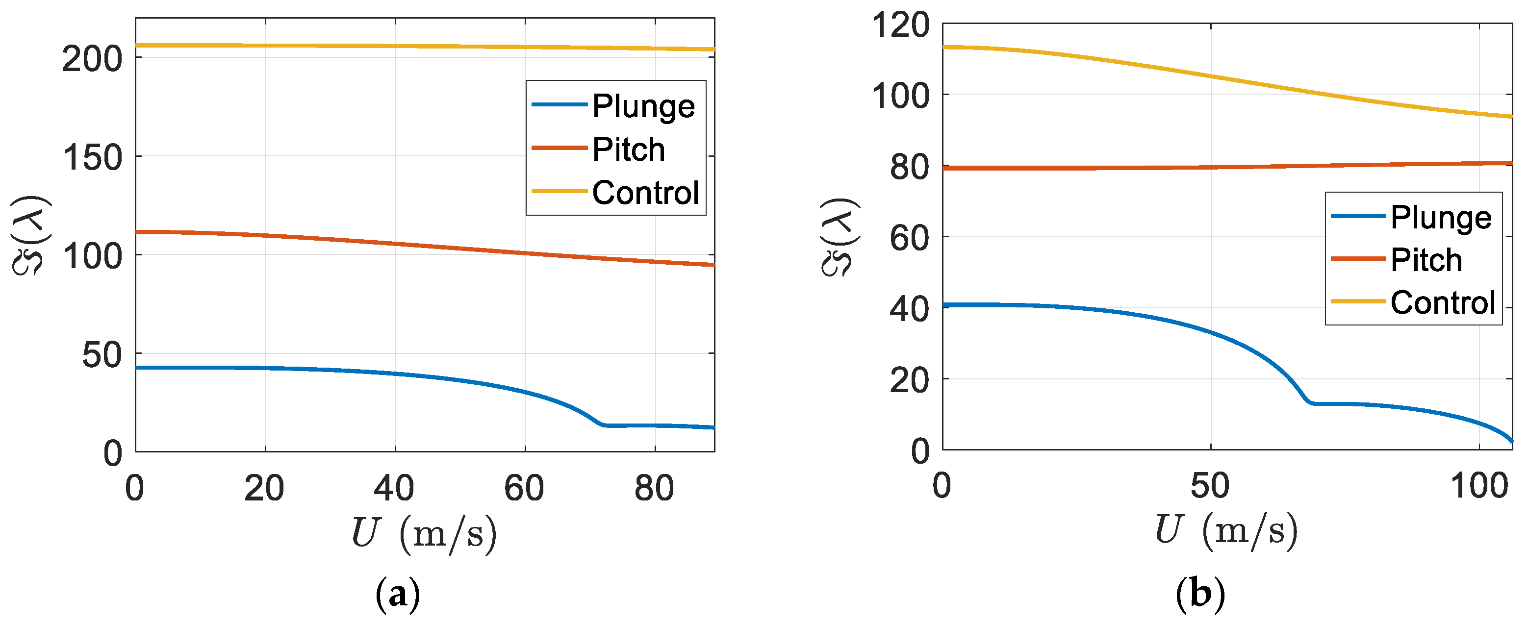
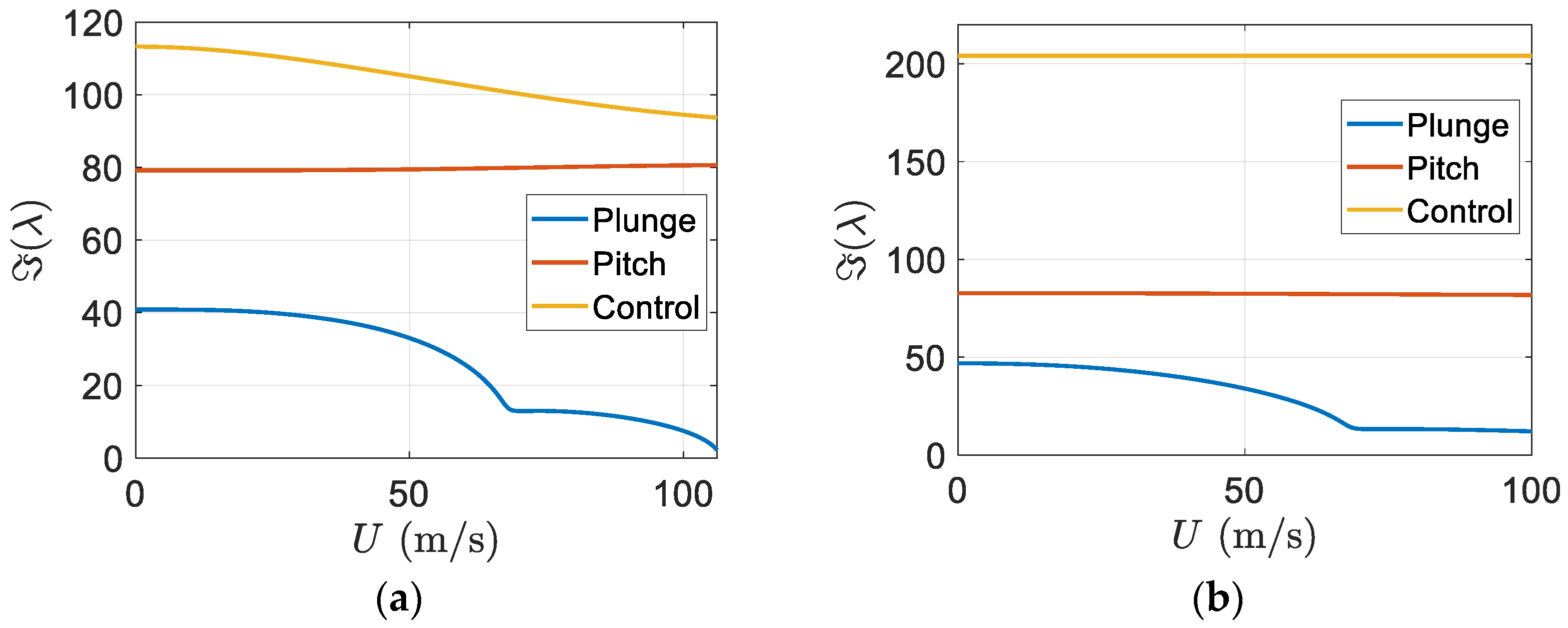
Furthermore, the imaginary part of eigenvalues versus the freestream velocity is depicted in
Figure 13.
Figure 13b shows that flutter appeared in the pitch mode and there was an effective increase in the flutter speed of the smart wing in comparison to the regular wing.
By using Equation (8), the matrix can be formed and its eigenvalues and eigenvectors can be calculated for two different airspeeds, and the flutter speed, . There are six complex eigenvalues which represent the structural state dynamics of the smart wing. These complex eigenvalues are conjugates of those of the regular wing. There are six real eigenvalues for the aerodynamics state dynamics. Furthermore, there are two real eigenvalues representing the piezoelectric state dynamics. In each eigenvector, the first three elements give structural velocities, the next three correspond to structural displacements, the next six elements represent aerodynamic state displacements, and finally, the last two are for piezoelectric electric charge.
The smart wing eigenvalues for the three structural modes at
are as follows
and its corresponding eigenvectors which present the smart wing structural mode shapes are
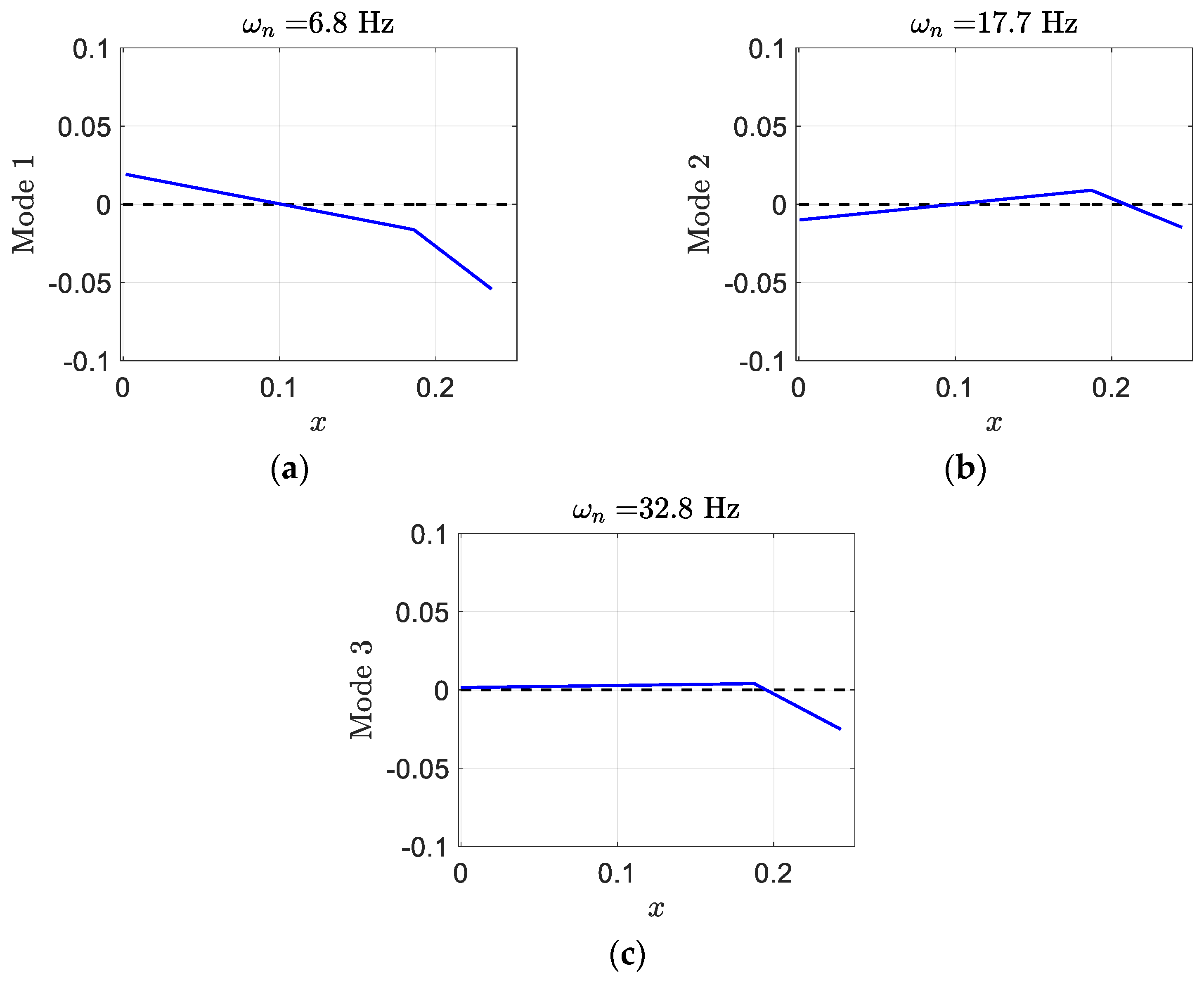
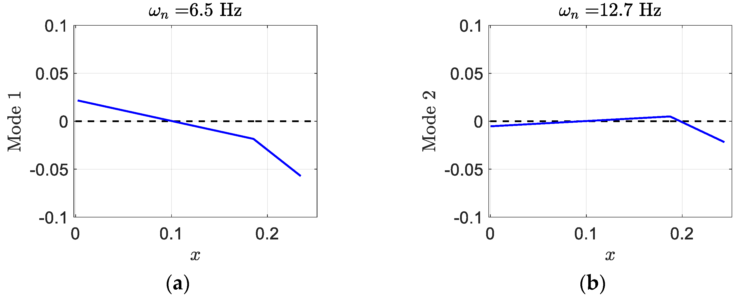
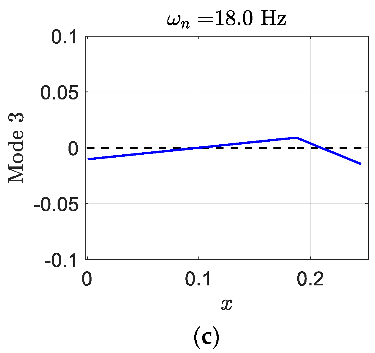
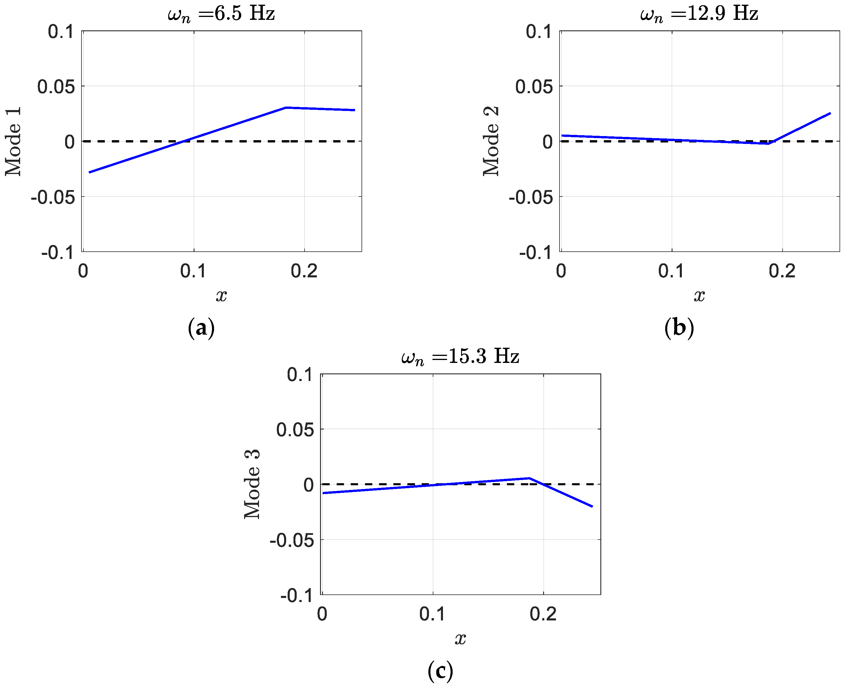
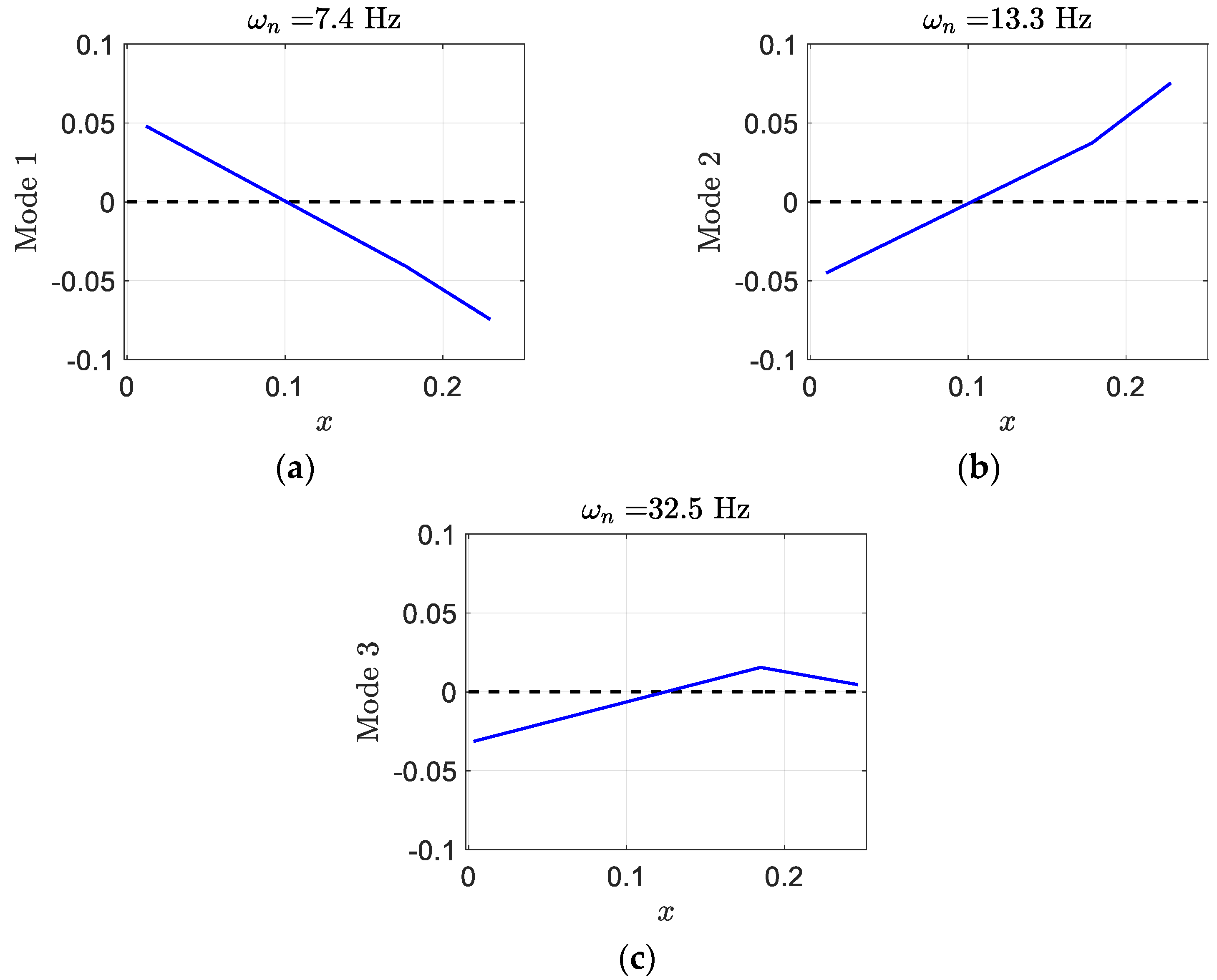
where, in each mode shape, the first element presents plunge displacement, the second one indicates pitch angle, and the last one gives control surface angle. Generally, in aeroelastic systems, the degrees of freedom are coupled to each other and cannot occur independently. Mostly, control surface and pitch displacements happen in mode two and three. Despite the regular wing, mode one contains significant pitch angle. The smart wing deformation in the three modes has been depicted in
Figure 14. There is almost similarity in pitch and control in modes two and three; however, there is significant pitch in mode one.
In addition, the smart wing eigenvalues at airspeed
are
and its corresponding mode shapes are
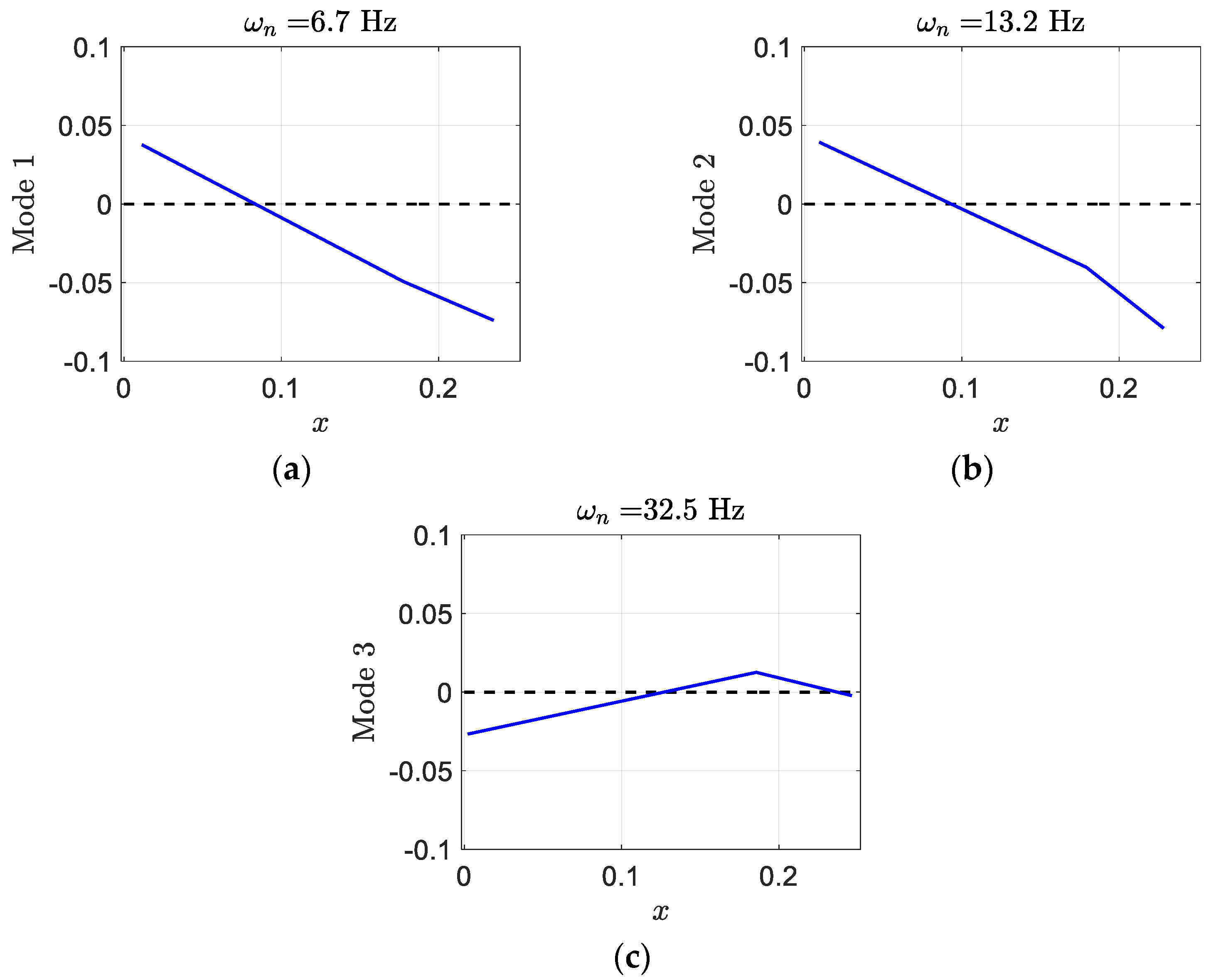
In comparison to eigenvalues at airspeed
, the real parts of
are much more negative, and the real part of
is almost zero. In addition, at
, the control components of mode shapes
and
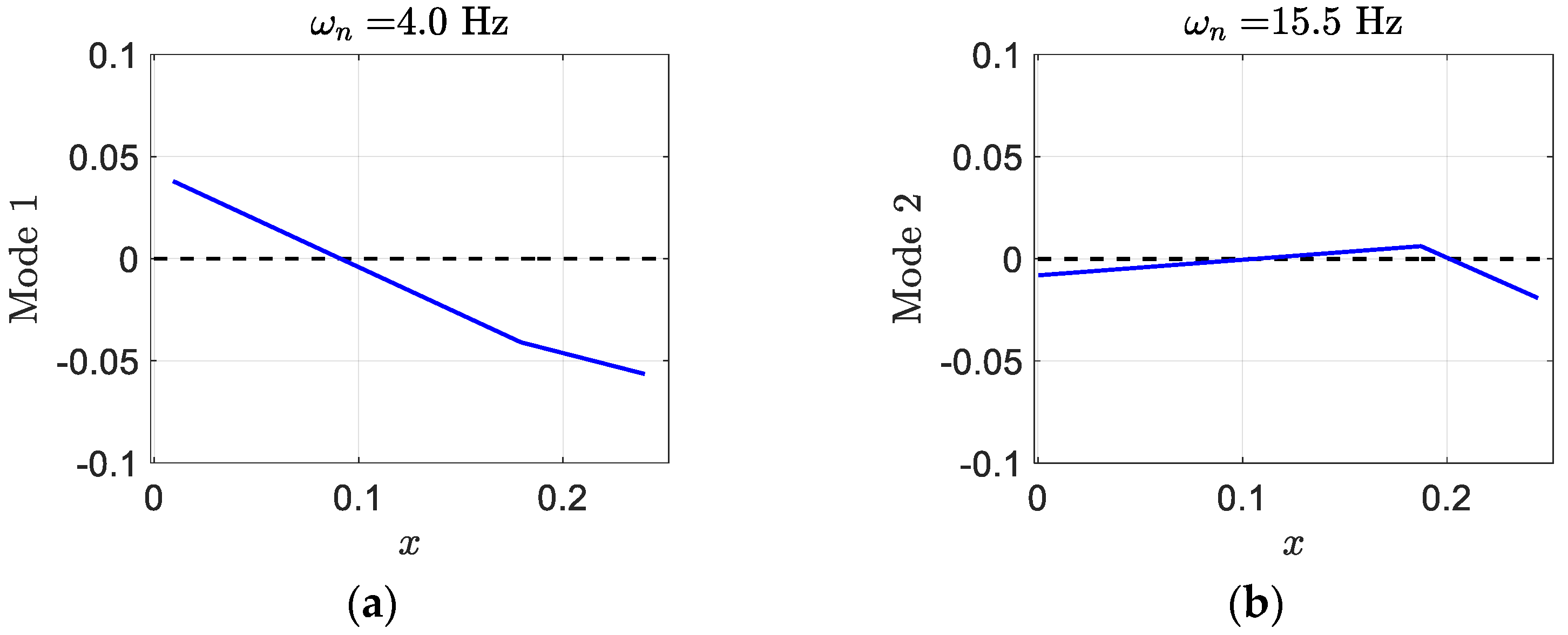
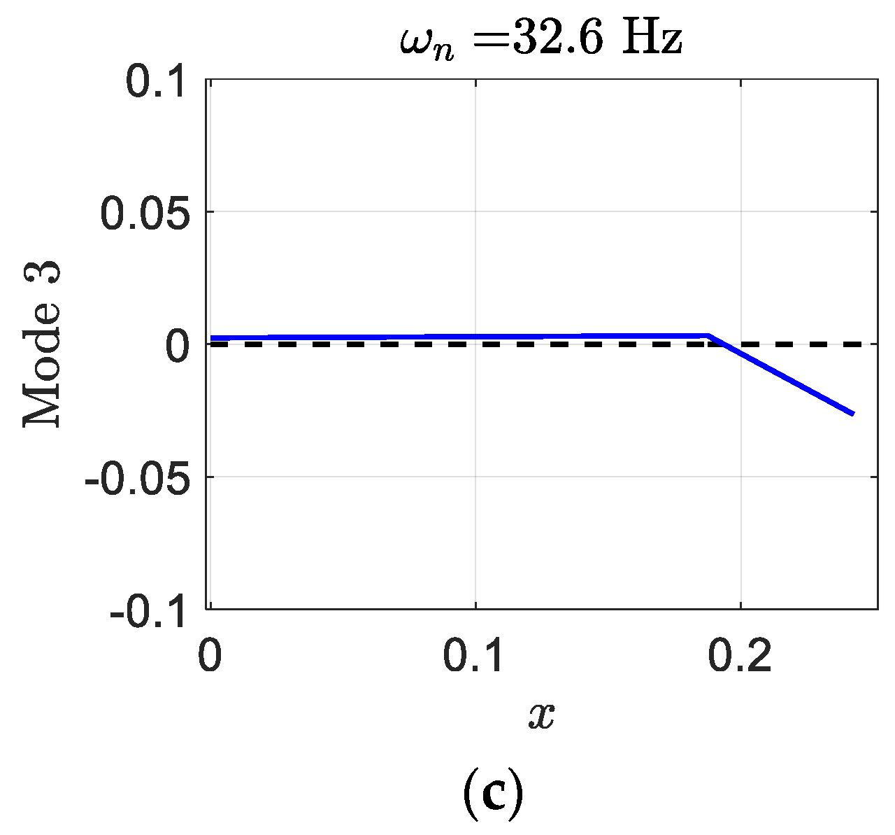
are very close together and there is a significant pitch in mode one, as shown in
Figure 15.
In
Section 4, a smart wing with three DOF and two piezopatches in the plunge and pitch DOF, called piezo-plunge-pitch-wing, is presented to illustrate its behavior in comparison to a regular wing in aeroelastic analysis and how implementing two piezopatches can further postpone the flutter phenomenon on a smart wing.
4. A Smart Wing with Plunge, Pitch, and Control DOF and Piezopatches in Plunge and Pitch DOF
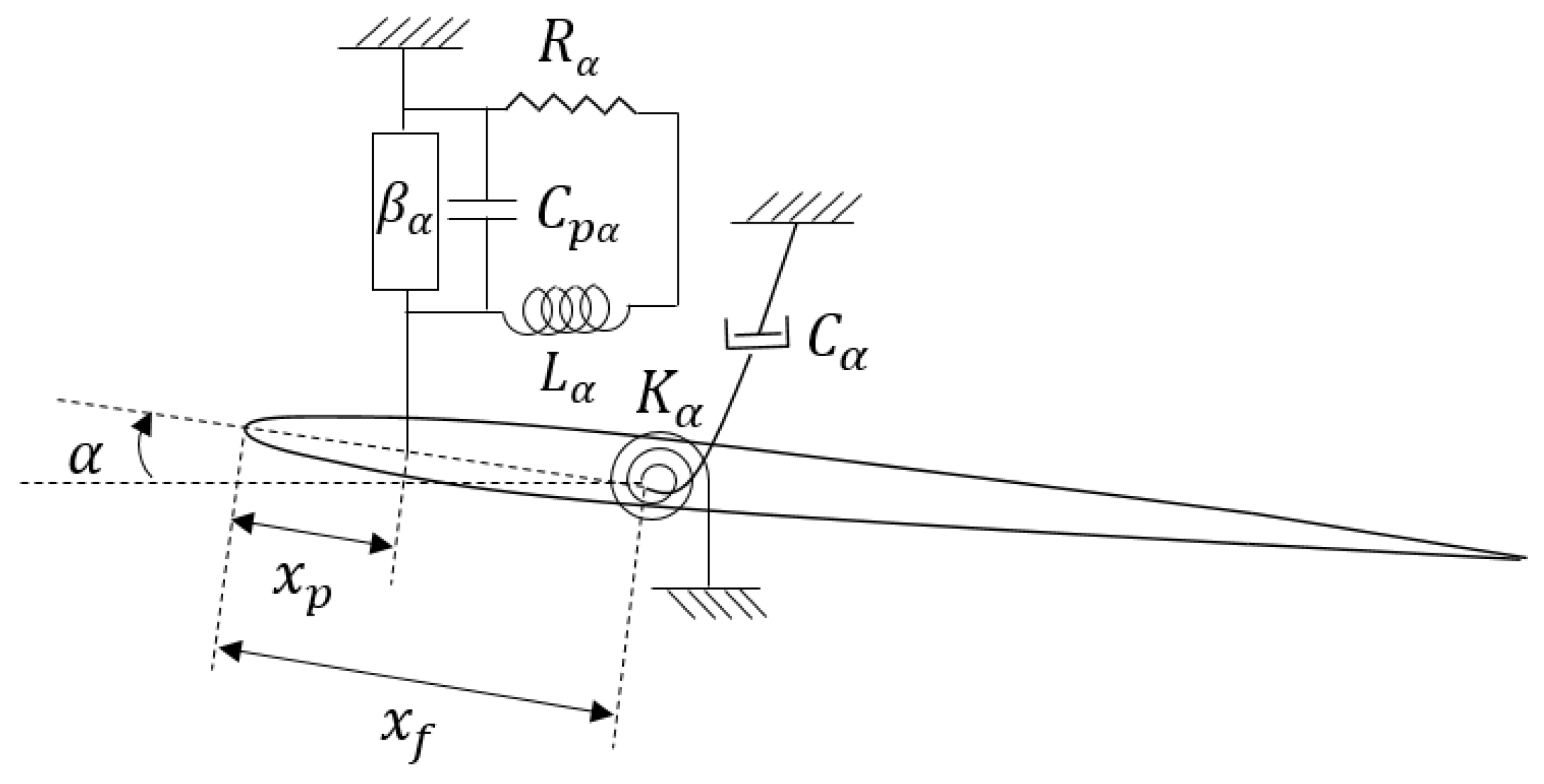
A 2D smart wing with plunge, pitch, and control DOF which has two piezopatches, one in the plunge DOF and the other in the pitch DOF, is considered, as indicated in
Figure 16; it can be called a piezo-plunge-pitch-wing. The system has the same characteristics of the piezo-plunge-wing in
Section 3.
The equations of motion of the smart wing can be obtained by using the Lagrange’s equations and the Kirchhoff’s law as
where
,
,
,
,
,
,
,
,
,
,
,
,
,
,
,
,
,
,
,
,
, and
are defined as in Equation (1),
is the pitch inductance of piezoelectric material,
is the pitch resistance of piezoelectric material,
is the pitch capacitance of piezoelectric material,
is the pitch electromechanical coupling, and
is the pitch electric charge. The pitch electromechanical coupling,
, depends on the pitch coupling coefficient,
, and the pitch capacitance,
, and it can be calculated by
.
Similar to
Section 3, the full unsteady aeroelastic equations of motion can be written as
where
is the displacement and charge vector.
Equation (29) can be written in purely first order ordinary differential equations form by
where
where
is the
state vector,
,
is a
unit matrix,
is a
matrix of zeros,
is a
matrix of zeros,
is a
matrix of zeros, and
is a
vector of zeros. The initial conditions are
. The initial condition
is an excitation whose effect decays exponentially. In order to obtain steady-state solutions, the initial condition is ignored in this paper therefore Equation (30) becomes
Example 4. A smart wing with plunge, pitch, and control DOF and a piezopatch in plunge and pitch DOF in aeroelastic analysis.
In the fourth example, an additional piezopatch was used to control vibrations in pitch DOF in the smart wing in example three. Therefore, a smart wing with plunge, pitch, and control DOF and two piezopatches, one in the plunge and the other in the pitch DOF, as shown in
Figure 16, was considered with the following parameters. It assumed the same characteristics as the smart wing existing in example three with the pitch piezopatch parameters as the pitch coupling coefficient
, the pitch capacitance of piezoelectric material
, the pitch inductance of piezoelectric material
, and the pitch resistance of piezoelectric material
.
Simulation results indicated that adding an additional piezopatch in the pitch DOF can remove the flutter phenomenon in the pitch mode, as depicted in
Figure 17. Hence, by having two piezopatches, one in the plunge and the other in the pitch DOF, it is possible to avoid flutter in both DOF. However, there was flutter in the control DOF.
Figure 17 shows that the smart wing with two piezopatches has flutter at
in the control DOF, which indicates a
increase in the flutter speed of a regular wing with the same characteristics without the piezopatch and a
increase in the flutter speed of a smart wing with the same characteristics that has only one piezopatch in the plunge DOF. Clearly, using two piezopatches can remove the flutter phenomenon in the plunge and pitch modes, but flutter happens in the control mode, as shown in
Figure 17b.
Furthermore, the real part of eigenvalues versus the freestream velocity has been depicted in
Figure 18. In
Figure 18b, it can be seen that there is no flutter in the plunge and pitch modes; however, flutter appears in the control mode. There is also a considerable increase in the flutter speed of the smart wing with two piezopatches in comparison to that of the smart wing with only one piezopatch.
In addition, the imaginary part of eigenvalues versus the freestream velocity is indicated in
Figure 19.
Figure 19b shows that flutter appears in the control mode and there is an effective increase in the flutter speed of the smart wing in comparison to the regular wing.
By using Equation (31), the matrix can be formed, and its eigenvalues and eigenvectors can be calculated for two different airspeeds, and the flutter speed, . There are six complex eigenvalues which represent the structural state dynamics of the smart wing. These complex eigenvalues are conjugates of those of the regular wing. There are six real eigenvalues for the aerodynamics state dynamics. Furthermore, there are four real eigenvalues representing the piezoelectric state dynamics. In each eigenvector, the first three elements give structural velocities, the next three correspond to structural displacements, the next six elements represent aerodynamic state displacements, and finally, the last four are for piezoelectric electric charges.
The smart wing eigenvalues for the three structural modes at
are as follows
and its corresponding eigenvectors which present the smart wing structural mode shapes are
where, in each mode shape, the first element presents plunge displacement, the second indicates pitch angle, and the last element provides control surface angle. Generally, in aeroelastic systems, the degrees of freedom are coupled to each other and cannot occur independently. Mostly, control surface and pitch displacements happen in mode two and three. In contrast to the regular wing, mode one contains significant pitch angle. The piezo-plunge-pitch-wing deformation in the three modes has been depicted in
Figure 20. It is clear that there is slight similarity in pitch and control in mode two and three; however, there is significant pitch in mode one.
In addition, the smart wing eigenvalues at airspeed
are
and its corresponding mode shapes are
In comparison to eigenvalues at airspeed
, the real parts of
and
are much closer, the real part of
is much more negative, and the real part of
is almost zero. In addition, at
, the control components of mode shapes
and
are almost symmetrical, and there is a significant pitch in mode one, as shown in
Figure 21.
Next section presents a smart wing with three DOF and three piezopatches in the plunge, pitch, and control DOF, called a piezo-plunge-pitch-control-wing, to illustrate its behaviour in comparison to a regular wing in aeroelastic analysis, and how using three piezopatches can completely remove the flutter phenomenon on a smart wing.
5. A Smart Wing with Plunge, Pitch, and Control DOF and Piezopatches in the Plunge, Pitch, and Control DOF
A 2D smart wing with plunge, pitch, and control DOF which has three piezopatches, one in the plunge DOF, one in the pitch DOF, and the other one in the control DOF, is considered as indicated in
Figure 22; it can be called a piezo-plunge-pitch-control-wing. The system has the same characteristics of the smart wing in the previous section.
The equations of motion of the smart wing can be obtained by using the Lagrange’s equations and the Kirchhoff’s law as
where
,
,
,
,
,
,
,
,
,
,
,
,
,
,
,
,
,
,
,
,
,
,
,
,
, and
are defined as in Equation (28),
is the control inductance of piezoelectric material,
is the control resistance of piezoelectric material,
is the control capacitance of piezoelectric material,
is the control electromechanical coupling, and
is the control electric charge. The control electromechanical coupling,
, depends on the control coupling coefficient,
, and the control capacitance,
, and it can be calculated by
.
Similar to
Section 3, the full unsteady aeroelastic equations of motion can be written as
where
is the displacement and charge vector.
Equation (35) can be written in purely first order ordinary differential equations form by
where
where
is the
state vector,
,
is a
unit matrix,
is a
matrix of zeros,
is a
matrix of zeros, and
is a
vector of zeros. The initial conditions are
. The initial condition
is an excitation whose effect decays exponentially. In order to obtain steady-state solutions, the initial condition is ignored in this paper; therefore, Equation (36) becomes
Example 5. A smart wing with plunge, pitch, and control DOF and a piezopatch in plunge, pitch, and control DOF in aeroelastic analysis.
In the fifth example, an additional piezopatch was used to control vibrations in control DOF in the smart wing in example four. Therefore, a smart wing with plunge, pitch, and control DOF and three piezopatches, one in plunge, one in pitch, and the other in control DOF, as shown in
Figure 22, was considered with the following parameters. It assumed the same characteristics for smart wing existing in example four with the control piezopatch parameters as the control coupling coefficient
, the control capacitance of piezoelectric material
, the control inductance of piezoelectric material
, and the control resistance of piezoelectric material
.
Simulation results indicated that adding an additional piezopatch in the control DOF can remove the flutter phenomenon in the control mode, as depicted in
Figure 23. Hence, by having three piezopatches, one in the plunge, one in the pitch, and the other in the control DOF, it is possible to avoid flutter in all DOF, eradicating all flutter.
Figure 23b shows that the smart wing with three piezopatches has no flutter. Using three piezopatches can remove the flutter phenomenon completely in the plunge, pitch, and control modes, as shown in
Figure 23b.
Furthermore, the real part of the eigenvalues versus the freestream velocity has been depicted in
Figure 24. In
Figure 24b, it is clear that there is no flutter in the plunge, pitch, or control modes.
Moreover, the imaginary part of eigenvalues versus the freestream velocity has been shown in
Figure 25.
Figure 25b indicates flutter does not appear in the smart wing.
By using Equation (37), the matrix can be formed and its eigenvalues and eigenvectors can be calculated for two different airspeeds, and the flutter speed, . There are six complex eigenvalues which represent the structural state dynamics of the smart wing. These complex eigenvalues are conjugates of those of the regular wing. There are six real eigenvalues for the aerodynamics state dynamics. Furthermore, there are six real eigenvalues representing the piezoelectric state dynamics. In each eigenvector, the first three elements give structural velocities, the next three correspond to structural displacements, the next six elements represent aerodynamic state displacements, and finally, the last six are for piezoelectric electric charges.
The smart wing eigenvalues for the three structural modes at
are as follows
and its corresponding eigenvectors which present the smart wing structural mode shapes are
where, in each mode shape, the first element presents plunge displacement, the second indicates pitch angle, and the last element gives control surface angle. Generally, in aeroelastic systems, the degrees of freedom are coupled to each other and cannot occur independently. Mostly, control surface and pitch displacements happen in mode two and three. In contrast to the regular wing, mode one contains significant pitch angle. The smart wing deformation in the three modes has been depicted in
Figure 26. It is clear that there is almost symmetry in pitch in modes one and two; however, their values are significant.
In addition, the smart wing eigenvalues at airspeed
are
and its corresponding mode shapes are
In comparison to eigenvalues at airspeed
, the real parts of
and
are much closer, the real part of
is much more negative, and
and
are close to those for
. In addition, at
, the plunge component of mode shape
is much higher than that of
. Furthermore, there are significant pitches in modes one and two, as shown in
Figure 27.
