Abstract
Unmanned aerial vehicles (UAVs) have been gaining increased importance due to their variety of applications. In some specific tasks, UAVs require the addition of payloads and onboard components, including sensors, which require great stability to provide safe and reliable responses (related to the payload characteristics, such as the temperature, pressure, vibrations and many other factors). In contrast with the suspended payloads carried by a quadrotor aircraft with a rigid attachment, an elastic attachment is designed to assess the influence of the vibration characteristics on the quadrotor and its payload. Since the payload dynamics can alter the flight performance, sensor measurement accuracy and payload integrity, an adapted sliding mode control is used to guide the quadrotor on its desired trajectory and to compensate for the payload dynamics. To reduce the need for position sensors, a reduced-dimension observer is designed to estimate the payload trajectory, as well as the external disturbance behavior. Numerical simulations are performed to demonstrate that the flexibility influences the quadrotor’s dynamics and can create residual oscillation on its payload.
1. Introduction
Unmanned aerial vehicles (UAVs) have attracted considerable research attention due to their variety of applications. Search and rescue, medical product delivery [,], mapping [], agricultural [,,] and surveillance [,,] operations are just some of the areas where UAVs are being deployed. In some cases, the use of UAVs can increase operations efficiency by reducing the delivery time, need for personnel and costs. The most common UAV configuration found in industrial applications is the quadrotor design, a four-propeller aircraft design. In the presence of attached loads such as sensors or compartments to carry medical goods and organs, the quadrotor dynamics can be significantly altered, creating unwanted vibration in the system []. This undesired vibration can negatively affect the quadrotor aircraft’s performance, as well as its payload integrity and sensing accuracy [,].
In the medical field, UAVs are employed since the delivery time is crucial for organs and pharmaceutical goods. In [], a smart cooler was attached directly to a UAV’s body. Wireless biosensors and barometric pressure, altitude, vibration and GPS sensors were placed alongside the organ (in the compartment) to measure its characteristics along the desired path. These experiments were conducted to verify the feasibility of quadrotor transportation despite the potential damage to the organs tissues that would occur if they were subjected to specific vibration amplitudes and frequencies. In [], the effects of vibrations caused by UAVs were compared with traditional road transportation. Insulin was used as the cargo, since its sensitivity to vibration can lead to the degradation and loss of its efficacy. Experimental trials have shown that the overall vibration levels caused by UAV flights are significantly higher than those caused by road transportation. Therefore, establishing the frequency-dependent sensitivity of a medicine to vibration is a prerequisite to safely planning a UAV mission.
The addition of an attached payload has a significant influence on the quadrotor’s dynamics, since it might change its flight characteristics, in addition to creating new uncertainties in the controller design. Different controller techniques related to payload vibration have been investigated, such as an extended high-gain observer [], active vibration absorption [], polynomial trajectories [] and adaptive controllers []. In [], a neuro sliding mode control (NSMC) as designed to compensate for the uncertain dynamics over time. The neuro technique was combined with the sliding mode control in order to successfully control the system changes without previous knowledge of the quadrotor and its payload dynamics.
Different techniques and controller designs for the payload are frequently found in the literature. In [], a high-level nonlinear controller using feedback linearization was chosen to guide a quadrotor along the desired trajectory. The oscillation of the load was modeled as a disturbance, and the proposed controller was then used to stabilize the quadrotor and its payload. In [], two controllers (proportional derivative (PD) and sliding mode control (SMC)) were used to investigate the mass uncertainties of the quadrotor dynamics. In the presence of large uncertainties, the PD failed to successfully control the tracking trajectory and quadrotor stability, while the SMC presented better robustness against disturbances. In [], the effects of payloads on UAVs and helicopters were investigated. Proportional integral and derivative (PID) control was chosen to assess the UAV stability under differing parameter variations, such as payload changes and offset loads (not centered to the vehicle’s CoG).
Overall, the payload dynamics are treated as a disturbance force, and a rigid attachment is often considered to obtain the mathematical formulation. In [], the damping of a cable-suspended payload was investigated. A feedback controller was combined with sliding mode control to reduce the payload vibration caused mainly by the quadrotor’s horizontal motion. The numerical simulations showed superior payload vibration suppression (by over 56%) in comparison to the traditional zero-vibration derivative–derivative (ZVDD) input shaper. In [], two other nonlinear controllers were designed for stabilizing a suspended load carried by a quadrotor. The control laws utilized the direct relationship between the payload oscillation and aircraft’s horizontal movement. Therefore, the proposed controller law could simultaneously guarantee both the desired trajectory optimization and payload oscillation reduction. Experimental trials have shown positive results for the swing suppression system.
In [], a backstepping technique was combined with swing damping to attenuate the suspended payload oscillations and external disturbances. The proposed controller was evaluated using simulations and experiments, showing a great reduction in angular displacement. In [], a dynamic program was developed to ensure the swing-free trajectory tracking of a quadrotor carrying a suspended payload. A real-time embedded controller was chosen to generate an optimal trajectory by sending updated controller inputs to the quadrotor. Then, the optimal trajectories suppressed the residual oscillations to less than 5% of their initial magnitudes.
Given this context, a nonlinear controller based on the backstepping technique was also used to ensure the trajectory tracking regardless of the payload motion []. First, the payload was modeled as a pendulum and a rigid attachment was assumed between the UAV and its payload. Then, the backstepping control was used to generate a reference trajectory, while the input–shape filtering approach was chosen to minimize the residual oscillation of the payload. The proposed controller perfectly negated the impact of the load movements, as well as allowed better tracking of the desired trajectory.
External disturbances can also negatively affect a UAV and its payload performance by increasing the undesired vibration. A disturbance attenuation control was proposed in [] to enhance the quadrotor stabilization under external disturbances. This approach introduced an adaptive parameter for the position control to estimate the payload mass and improve the robustness of the system. The estimated payload mass was then combined with the state feedback control with the aim of enhancing the trajectory tracking performance and disturbance rejection. The simulation results demonstrated better responses than those obtained with the traditional sliding mode control (SMC) when considering unknown mass and air disturbances. In [], the wind influence presented a direct impact on the aircraft’s fuel consumption. A generic algorithm was used to optimize the trajectory selection in order to avoid head winds. This generic algorithm was then used to increase the flight performance and to strongly reduce the fuel consumption.
Sensors reduce a UAV’s capacity and significantly increase the overall costs. In [], a pitch motion controller was proposed for active disturbance rejection and trajectory tracking. A state feedback controller was combined with a generalized extended state observer (GESO) to create longitudinal disturbance rejection for the UAS-S4 Ehécatl UAV. Simulation results demonstrated that the proposed controller was able to properly estimate and compensate for the external disturbances to the UAS-S4 by guaranteeing more stable trajectory tracking. In addition, the UAS-S4 aerodynamic model was experimentally validated [,,,,] at the LARCASE laboratory [].
Several observer strategies have been proposed to suppress the negative influences of unwanted vibrations caused mainly by external disturbances, parameter uncertainties and actuator faults. The combination of sliding mode control (SMC) with a disturbance observer (DO) was addressed in []. External disturbances were attenuated by the DO, while the uncertainties were reduced by the use of adaptive schemes in the SMC design. This adaptive controller was used to accurately compensate for the control input and to avoid control parameter overestimation. In [], the state feedback control was combined with an adaptive observer for the stabilization and suppression of uncertainties. The adaptive observer and feedback controller were designed to estimate the magnitude of uncertainties and to stabilize the closed-loop system, respectively.
Multiple observers were employed for anti-disturbance control of a quadrotor. In [], a disturbance observer (DO) and an extended state observer (ESO) were utilized in the position loop to attenuate the impacts of the suspended payload dynamics and wind disturbances. They ensured that the payload oscillation was reduced and that the wind estimation error was minimal. Experimental trials demonstrated that its effectiveness was approximately 75% higher than the classical PID controller.
Flexible aircraft dynamics is commonly studied in the aeronautical field as it relates to flexible wings [], flutter suppression of flexible structures [] and vibration reductions []. In [], a model predictive control (MPC) was developed to alleviate the influence of gusts on a highly flexible aircraft. An additional feedback loop was then included on the controller design to increase the UAV performance and gust load suppression. In [], a long-endurance UAV dynamics model was studied to assess its stability, control and performance. The control inputs were calculated by using the nominal dynamic equations, while the eigenvalues of the perturbation equations were used to verify the UAV’s stability. The results of the proposed model were compared with those of two frequently used models: a quasi-rigid aircraft and a restrained aircraft. The characteristics of the controller can change in terms of stability depending on the chosen model. Thus, an aircraft’s flexibility significant influences its dynamics and structural components.
This article investigates the payload vibration characteristics when a swing load and an elastic attachment are considered using different flight configurations. The main contributions of this paper are: (i) the attachment configuration of a suspended payload using constraint force representation; (ii) the use of an adaptive sliding mode control to compensate for both the altitude controller and the quadrotor dynamics; (iii) the design of a reduced-dimension observer (RDO) for an 11 degrees of freedom quadrotor model. These combined strategies are used to study the feasibility of a commercial quadrotor for medical transportation in low-income countries, without the need for additional damping absorbers or high-cost quadrotors. Therefore, the effects of the trajectory, payload weight, wind velocity and elastic attachment on the dynamics of the quadrotor and its payload are then evaluated.
2. Materials and Methods
Two main coordinate frames are used to describe the quadrotor motion: inertial () and body-fixed (). The inertial frame is defined on the ground surface, while the body-fixed frame is defined on the quadrotor’s center of geometry (CoG). The coordinate frames are composed of six degrees of freedom; the inertial frame corresponds to the altitude and position () and to the attitude () of the quadrotor, while the angular () and linear () velocities are used to define the body-fixed reference frame. Figure 1 depicts a schematic illustration of a quadrotor transporting a payload.
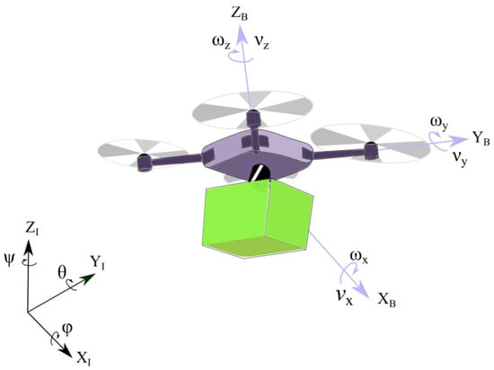
Figure 1.
Schematic illustration of a quadrotor carrying a payload.
Five additional degrees of freedom are used to represent the payload motion. While and represent the payload position, the terms and represent the payload rotation. In addition, the connection between the quadrotor and its payload is assumed to be an elastic attachment, in which is the resultant of constraint force components ( and ). Each of the constraint forces components is represented by (where and is the physical distance between the quadrotor and its payload. Regarding the constraint force, the first term represents the elastic attachment, while the second term denotes the swing angle influence. Figure 2 shows the elastic attachment between the quadrotor and its payload, where and are the quadrotor and payload masses, respectively.
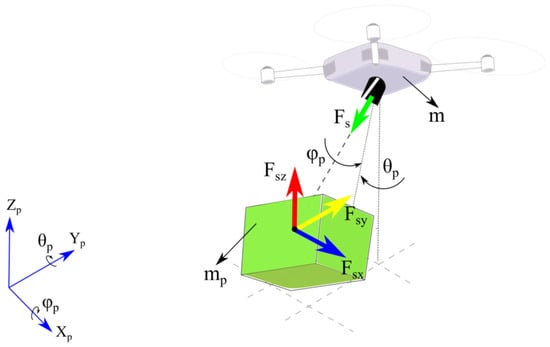
Figure 2.
Schematic illustration of the payload dynamics, showing the attachment constraint forces.
The combination of the swing load and elastic attachment dynamics allows the payload to move and vibrate freely in the three-dimensional trajectory with respect to the quadrotor’s motion.
Equation of Motion
The equation of motion for a quadrotor carrying a payload is presented in Equation (1):
where is the inertial matrix, represents the Coriolis matrix, is the stiffness matrix, is the gravitational vector, is the input control vector, and and are the external disturbance and constraint forces vectors, respectively. The generalized coordinate vector is defined by 11 degrees of freedom ().
The distance vector between the quadrotor and its payload is defined by , where and are the cosine and sine functions, respectively. The inertial matrix ( can also be represented as follows:
while the Coriolis and stiffness are similarly represented. The gravitational vector is defined by }, while the control input is calculated by the following expression . The matrices and vectors from the equation of motion can also be written in the body-fixed reference frame, as shown:
where , such that and are the moments of inertia of the quadrotor and its payload along and , respectively. The payload moment of inertia is calculated using a load-correcting factor (, where and , as defined in Section 3.1.1, and the indicates a diagonal matrix. The inertial matrices and are defined below:
where . The Coriolis matrix is given by:
where and are represented by the following Equation (6):
where , , , and and are expressed as follows:
and:
The drag, aerodynamic and torque coefficients, due to the gyroscopic effect dynamics, are shown with Equation (9):
and ). The coefficients and are positive translation drag constants; and are the aerodynamic friction coefficients; is the rotor inertia; and is defined by the following relationship The angular velocities (where ) are calculated in []:
where and are the engine coefficients. Additionally, the relationship between the inertial and body references is represented by a Jacobian matrix (, given by:
where and are defined as follows:
where indicates the tangent function. In addition, , , , is the transformation matrix derivative with respect to time and the gravitational vector components are defined as and The stiffness matrix is defined by:
where , such that is the proportional stiffness component along its directions and . The stiffness submatrices are calculated using , and . Additionally, the control vector input is represented by , where and are the quadrotor control law inputs. In this sense, for numerical simulations, the second-order differential equation can be represented in state-space form as follows:
where is the state vector, is the input vector and is the gravitational vector. The dynamic and input matrices are represented as follows:
Due to the presence of an elastic attachment, the constraint forces are defined in all three directions, using the following representation . The vector is calculated as , yielding:
where , such that . The vector is defined by , yielding:
where . Afterwards, the Dryden disturbance force is applied in the three directions of the quadrotor ( and ), and it is represented as follows []:
where is the air density, is the drag coefficient, is the projected area of the quadrotor, and are the quadrotor the wind velocities along its direction () and indicates the signal function. Further steps of the Dryden force design can be found in [].
3. Controller Development
In this section, the altitude, position and attitude angles of the quadrotor are calculated using the sliding mode control (SMC) methodology. For the tracking trajectory, four input control laws () were designed based on the SMC method. In addition, due to the direct impact of the added payload on the altitude control, a coefficient () was estimated to compensate for the extra effort on the quadrotor dynamics and to attenuate the payload uncertainty. Figure 3 shows a schematic illustration of the controller design.
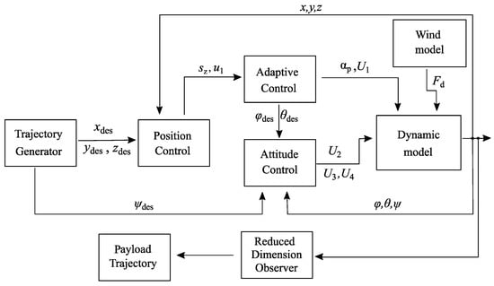
Figure 3.
Schematic illustration of the controller design.
3.1. Altitude Control Design
Sliding mode control (SMC) has become one of the most important types of nonlinear controller methods due to its simplicity and robustness. Overall, the SMC is designed using two steps for the stable sliding surface and the corresponding control law. The altitude sliding surface can be defined as follows []:
where indicates the error, i.e., the difference between the desired and actual trajectories of the quadrotor (), represents its time derivative and is the tuning parameter associated with the closed-loop bandwidth.
The sliding time derivative can be represented using different functions to enforce the proposed controller on the surface []. Thus, the following expression was chosen to improve the controller robustness and reduce the uncertainties influence. The term indicates the saturated function, while and are the sliding surface exponential coefficients. The corresponding control law is calculated by combining the time derivative of the sliding surface ), the proposed surface coefficients and the equation of motion of the quadrotor (as seen in []), yielding:
Since the quadrotor is an under-actuated system, the desired roll and pitch angles are associated with the motion along the () plane. Thus, two virtual inputs are defined and their corresponding control laws are represented by and , respectively. Given this context, the desired references for the attitude control are defined as follows:
where are positive constants. The modified control law is used to compensate for the unknown mass of the payload, as seen in Section 3.1.1.
3.1.1. Adaptive Altitude Control Design
The corresponding control law () is designed for a quadrotor with no load attached to it. In the presence of a payload, the total thrust force must compensate for both systems’ weights (the quadrotor and its payload) and their uncertainty masses. The estimated load-correcting factor multiplies the nominal mass value (), leading to . Now, by defining , the altitude adaptive law is represented as []:
where is a positive constant. Using this correction, the following relationship is then calculated. As mentioned previously, the load-correcting factor is not only applied to correct the altitude control, but also to compensate for the dynamics of the system (as seen in Appendix A). Further details regarding the stability can be found in [].
3.1.2. Stability Analysis
Consider the Lyapunov candidate function defined as To ensure that the dynamic system is stable, the Lyapunov candidate must be a strictly positive function, while its derivative must be a negative semi-definite for all states. By combining the time derivative of the Lyapunov candidate () with the chosen surface and equations of motion in the vertical direction, the stability proof leads to:
which guarantees the stability condition for the altitude state (). These steps can also be extended to the position and attitude control, as seen in [].
3.2. Attitude Control Design
Likewise, the control inputs and are calculated following the same steps. The attitude control laws are then calculated by combining the sliding surfaces (based on the attitude angles and ), chosen surface () and the quadrotor rotational equations of motion (as seen in []). In this sense, and are given by []:
where and have real positive constant values. Therefore, the combination of altitude, attitude and position control laws ensures that the quadrotor follows a three-dimensional trajectory. It is worth mentioning that a second-order sliding mode control is chosen due to its superior robustness and reduced uncertainties in comparison to the first-order SMC or PID, as shown in [].
3.3. Reduced-Dimension Observer (RDO)
An inertial measurement unit (IMU) and onboard sensors are frequently employed to measure quadrotors and their payload states. However, the use of a reduced-dimension observers offers an economical and efficient methodology to estimate the payload motion. The linear equation of motion is written in a state–space form representation [] as the following Equation (25):
where is the state vector, and are the linear dynamic and input matrices (of and ), is the control input and is the output state feedback. As the RDO aims to estimate only the payload motion, the output matrix is then calculated by using the following expression . Therefore, the state vector can be divided into measurable and unmeasurable states by , as addressed in []. This technique eliminates the redundancy of all state estimations (), since only the payload states are needed. The system can be written with Equation (26):
where the matrices and are found in Appendix B. The observer can be defined with Equation (27), as shown in []:
The observer law can also be written with Equation (28), by using the relationship , as addressed in []. The RDO equation is, thus, defined as:
The linear quadratic regulator (LQR) technique is chosen to calculate the RDO gain vector ().
4. Results and Discussion
The physical parameters of the mathematical model (quadrotor with an attached payload) used for numerical simulations are presented in Table 1. Table 2 lists the controller gains computed for the sliding mode control (SMC) design. The initial altitude and attitude states of the quadrotor and its payload were designed to have small displacements.

Table 1.
Physical parameters of the quadrotor.

Table 2.
Controller parameters.
The mathematical model for a suspended payload carried by a quadrotor is frequently assumed to have a rigid attachment, as widely addressed in the literature [,,,]. The elastic attachment assumption brings some important advantages to the system, such as the attenuation of impulsive forces on the payload. On the other hand, the relative displacement between the quadrotor and its payload can produce undesired oscillations, which compromise the cargo integrity and controller performance. In medical transportation by quadrotors, different amplitudes and intensities of vibration are generated, impacting on the medicine quality (since some pharmaceutical goods and organ tissues can deteriorate for specific oscillation frequencies).
The flexibility has been frequently studied in crane dynamics [,]; however, it is a very recent topic in UAV applications []. In addition, the motion produced by these relative trajectories leads to a decrease in controller performance, requiring high gains, adaptive controllers or the use of additional techniques to suppress residual oscillations. The combination of the swing load and elastic attachment is, therefore, evaluated to verify the characteristics during two proposed flight trajectories.
4.1. First Trajectory Configuration (Rectangular)
The rectangular flight trajectory is composed of take-off and cruise phases along the and directions. Figure 4 depicts the three-dimensional quadrotor and payload trajectories. For the mathematical modeling, the distance between the payload and quadrotor is defined by lb = 0.2.
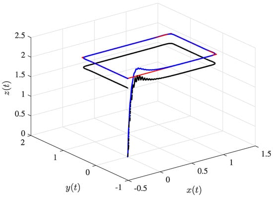
Figure 4.
Three-dimensional trajectories of the quadrotor and its payload, showing the desired trajectory (solid red line), quadrotor trajectory (solid blue line), and payload displacement (dashed black line).
As seen in Figure 4, there is no presence of external disturbance in the trajectory. Especially at the beginning of the flight, higher oscillation peaks are verified due to the rapid changes in acceleration and controller characteristics (as seen in Figure A2, which represents the sliding surface behavior). During the cruise phase, the SMC better attenuates the residual vibration due to its great robustness in dealing with boundary uncertainties.
4.1.1. Elastic Attachment Influence
Initially, a comparison between the dynamics of the elastic and rigid attachments is investigated. The take-off is analyzed since it generally comprises the fastest change in altitude (in comparison to other phases). In [], both the take-off and landing phases demonstrated significant vibration intensities in the payload compartment. Additionally, the take-off exhibited a larger period of vibration and higher amplitudes in comparison to the landing phase. Figure 5 shows the vertical displacement comparison between the elastic and rigid attachments on the quadrotor. Likewise, the control input (), responsible for lifting the quadrotor, suffers the same influence, while Figure 6 shows the control input for the elastic and rigid attachments.
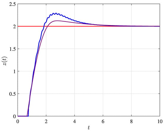
Figure 5.
Vertical displacement of the quadrotor, showing the elastic (solid blue line) and rigid (solid purple line) attachments.
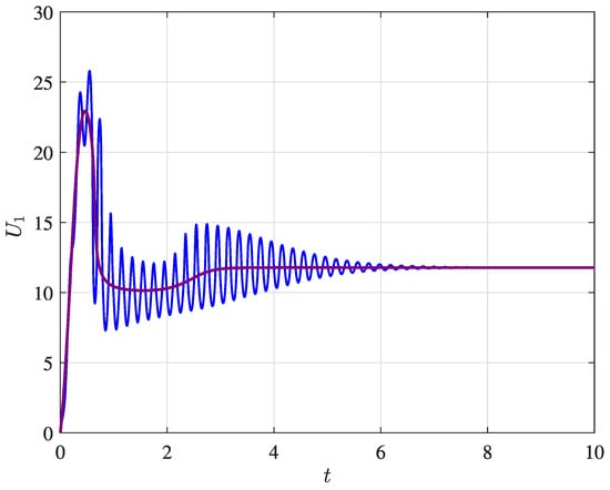
Figure 6.
Control input U1, showing the elastic (solid blue line) and rigid (solid purple line) attachments.
For simplicity, the elastic influence is shown only in the vertical direction; however, it also extends to the horizontal positions and the attitude angles. Figure 7 shows the roll angles, considering both the elastic and rigid attachment configurations. The undesired oscillation is presented along the trajectory, especially during maneuvers, along with its changes in direction.
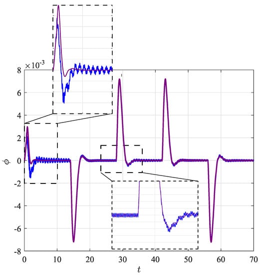
Figure 7.
Attitude state variable (), showing the elastic (solid blue line) and rigid (solid purple line) attachments.
As can be seen in Figure 7, an undesired oscillation is shown along the attitude state variable (), especially related to the take-off () and lateral motion (). In addition, the amplitude of the swing angles (using elastic attachment) is more than two times higher in comparison to the rigid attachment (as seen in Figure 8). The excessive vibration and lateral motion of the payload alter the quadrotor dynamics and impact on the controller performance. Therefore, the effects of an elastic attachment on the system dynamics must be evaluated to establish the cargo feasibility. The characteristics of the swing load dynamics are depicted in Figure 8 for both attachment configurations.
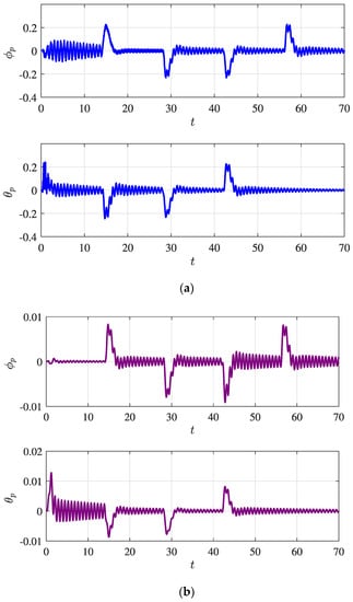
Figure 8.
Swing load dynamics, showing the (a) elastic attachment (solid blue line) and (b) rigid attachment (solid purple line).
4.1.2. Vibration Characteristics
The vibration characteristics are also assessed. These vibrations are calculated using the difference between the quadrotor and its payload trajectories, as represented by (). In addition, an external disturbance is applied to the quadrotor during a specific interval of time (limited by the dashed red lines) to simulate the outdoor environment. Both the elastic dynamics and swing dynamics change in the presence of external disturbances, since they are directly impacted. Figure 9 shows the relative displacement between the quadrotor and its payload along the and axes.
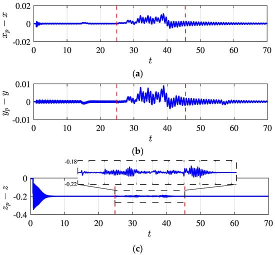
Figure 9.
Relative displacement along (a) x, (b) y and (c) z axes, showing the desired trajectory (solid red line) and the external disturbances during a time interval (dashed red line).
Next, the root mean square (RMS) technique is used to verify the level of vibration during the quadrotor flight. The RMS of the relative displacement under external disturbances is approximately 10 times higher than in the absence of this perturbation. For instance, in direction, the presence gives a value of 0.0037, while the absence gives a value of 0.0003023. Figure 10 shows the influence of the Dryden disturbance based on the wind velocity. The index represents the normalized wind velocity, while is the RMS of the quadrotor path under external disturbances (from 25 to 45 s).
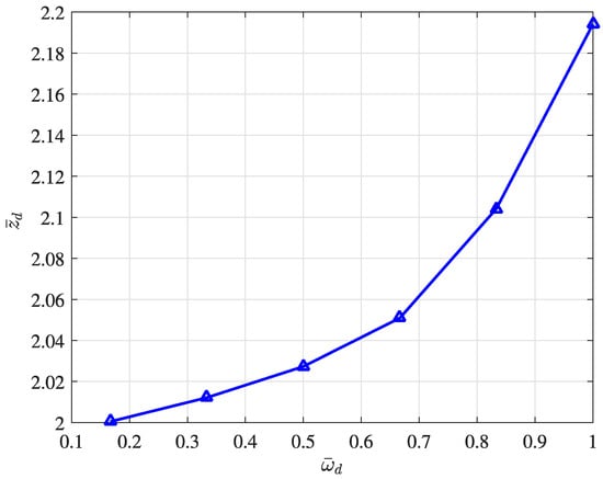
Figure 10.
Relationship between the wind velocity and undesired oscillation.
Based on Figure 10, according to the wind velocity, the payload can suffer higher oscillation amplitudes (in comparison to an indoor flight). It is worth noting that the range of wind velocity used is 0.5 to 3 m/s. Finally, in the presence of severe wind intensity, the controller performance is decreased, and this superior vibration can impact on the transported load integrity.
The RMS is also used to analyze the influence of the attached payload on the quadrotor trajectory performance. Figure 11 shows the relationship between the mass ratio and the RMS of the quadrotor oscillation during the take-off phase. It can be observed that represents the divided by the natural frequency of the system (as calculated in []), while is the ratio between the payload () and the quadrotor () masses.
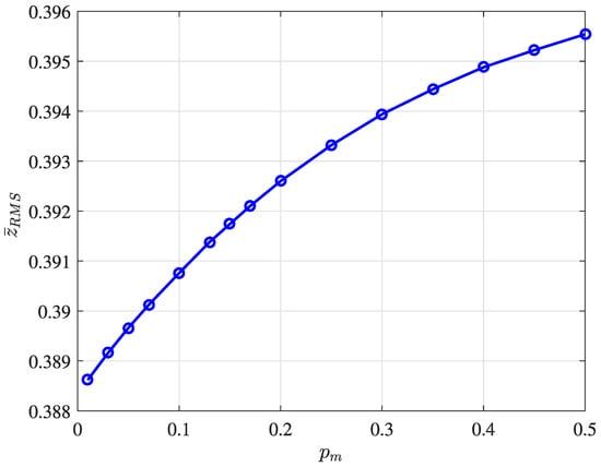
Figure 11.
Relationship between the quadrotor weight and trajectory performance during the take-off phase.
As demonstrated in [], the quadrotor often presents higher vibration intensity levels than those of traditional road transportation methods. Each product is affected by a different vibration intensity, and an understanding of this relationship will increase the successfully implementation of commercial quadrotors in the medical field. Therefore, depending on the proposed trajectory, attachment configuration and payload weight, there are several implications for the integrity of the medical goods.
Finally, to evaluate the attachment influence, the energy levels in the take-off (t < 10 s) and cruise phases were calculated. The payload weight was fixed in 20% of the quadrotor mass, while the stiffness ranged from to (axis ). Then, the stiffness was fixed in and the payload ranged from to (axis ). The reference parameters of and were 0.44 kg and 361.88 N/m, respectively. Figure 12 shows the normalized energy of each flight phase, by changing the payload weight () and attachment value ().
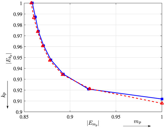
Figure 12.
Energy calculated by changing the payload weight and stiffness coefficient for take-off (solid blue line) and cruise (dashed red line) phases.
As seen in Figure 12 both the payload weight and stiffness coefficients impact on the unwanted oscillation trajectory. Lower stiffness values increase the undesired vibration ( closer to 1) and lead to higher payload weight values ( closer to 1). According to the RMS analysis, the range between to and to exhibits great performance in terms of energy. In addition, Section 4.2 presents a new flight configuration (circular trajectory) that is used to assess the vibration characteristics (between rigid and elastic attachments), as well as the main differences with respect to the first trajectory configuration.
4.2. Second Trajectory Configuration (Circular)
In this sub-section, a circular trajectory is used to assess the vibration characteristics in comparison to the first configuration (rectangular). It is worth mentioning that the lateral displacement amplifies the unwanted vibration and swing oscillations, since they are dependent on each other. Figure 13 depicts the circular trajectory of the quadrotor and its payload.
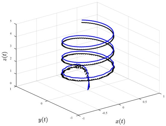
Figure 13.
Circular trajectory, showing the trajectories of the quadrotor (solid blue line) and its payload (dashed black line).
The attitude states (from the quadrotor and its payload) are compared to assess the differences between the rigid and elastic attachments. Figure 14 shows the undesired oscillation amplification for the elastic attachment.
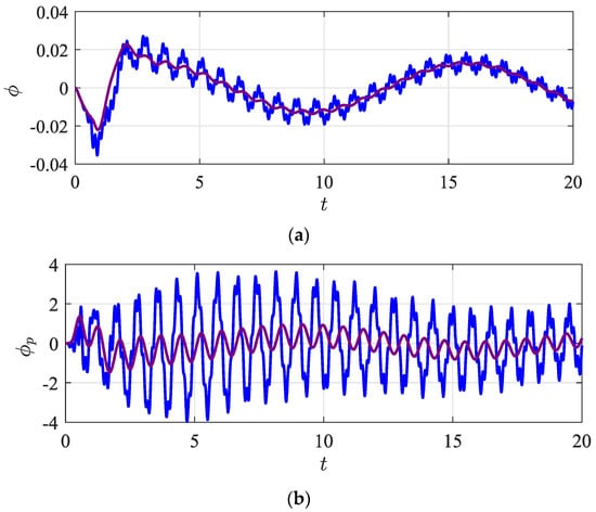
Figure 14.
Attitude state variables of the quadrotor () and its payload () for the (a) elastic attachment (solid blue line) and (b) rigid attachment (solid purple line).
The circular trajectory (Figure 13) exhibits significant increases in swing and elastic influence in comparison to the rectangular flight (as can be seen in Figure 7 and Figure 8).
In the first trajectory, the quadrotor mostly follows a cruise path, without changing the direction frequently; however, for the circular trajectory, the payload moves and vibrates more laterally due to the trajectory profile. Since the lateral component presents the most significant increase, Figure 15 shows the relative displacements along and directions.
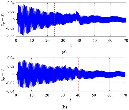
Figure 15.
Relative displacements between the quadrotor and its payload along (a) x and (b) y directions.
Thus, a smooth trajectory (i.e., slower changes in attitude or altitude) reduces the undesired relative trajectory and its swing load influence. Table 3 exhibits the ratio values for relative displacements between circular and rectangular trajectories ( along the direction. The mass ratio é is also calculated using the following relationship (, while the stiffness is changed proportionally to maintain the natural frequency of the payload at 5.

Table 3.
RMS percentagex of relative displacement, using both trajectory configurations (rectangular and circular).
As seen in Table 3, the RMS values of the circular trajectory are higher than those of the rectangular trajectory. The payload weight also impacts on the undesired oscillation in the circular trajectory, showing values 2.85 to 6.35 times higher than those of the rectangular trajectory. For instance, the RMS in the direction (at for the circular trajectory is 0.0094, while for the rectangular trajectory is 0.0020. Therefore, the combination of the payload, trajectory, elastic attachment and maneuvers directly impacts on the vibration characteristics.
The controller robustness is another parameter that influences the undesired vibrations of the system. Thus, the presence or absence of a chosen function () in the controller design is used to assess the vibration characteristics. Note that this function is chosen to improve the robustness of the control algorithm and to reduce uncertainties. Figure 16 depicts the influence of stronger reductions in uncertainties in the controller design.
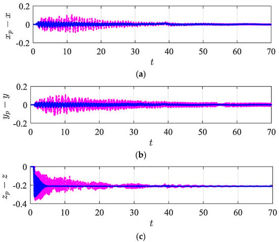
Figure 16.
Relative displacements (a) , (b) and (c) showing the presence (solid blue line) and absence (dashed pink line) of the chosen function in the control design.
As can be seen in Figure 16, the amplitudes of the relative trajectory are significantly decreased in the presence of the chosen function. This robustness improvement allows the quadrotor to smoothly follow the desired path, with the payload presenting lower undesired oscillations. Other aspects such as controller gains, time stabilization (to converge to the desired path), overshoot and errors have high levels of influence on the vibration behavior. Additional comparisons between SMC and PID can be found in [].
4.3. Reduced-Dimension Observer (RDO)
The reduced-dimension observer is utilized as an advantageous technique to estimate the payload trajectories, since it significantly reduces the overall price of the quadrotors (decreasing the need of additional sensors). The linear quadratic regulator (LQR) is used to calculate the controller gain vector L, as represented by the following matrix , where and . Figure 17 shows the lateral displacement of the payload using the reduced-dimension observer. The RDO estimated the first configuration trajectory; however, it can easily be extended for different flight configurations.
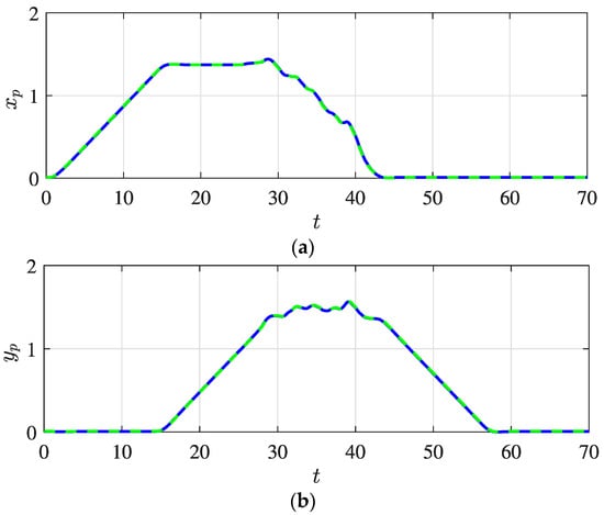
Figure 17.
Lateral payload trajectory using RDO (where (a) x axis and (b) y axis), showing the current (solid blue line) and estimated (dashed green line) paths of the payload trajectory.
As can be seen in Figure 17, the proposed RDO controller accurately estimates the lateral payload trajectory, including the characteristics of the external disturbance. The presence of external disturbances leads to trajectory deviation and consequently decreases the quadrotor and its payload stability. Figure 18 depicts an estimation of the payload’s vertical trajectory.
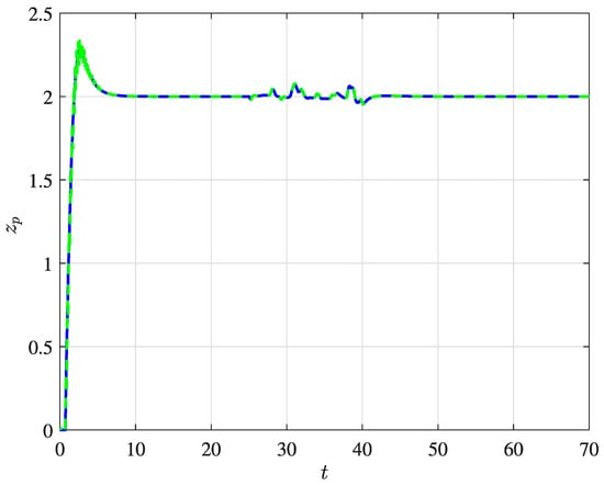
Figure 18.
Vertical trajectory of the payload using the RDO technique, showing the current (solid blue line) and estimated (dashed green line) paths.
In outdoor flights, the quadrotor is subjected to different wind intensities, which can substantially increase the amplitude of vibration. Several controller strategies have been proposed for disturbance attenuation; however, they have mostly been designed using boundary disturbances. The use of observers allows on to estimate the payload trajectory and then to obtain the disturbance characteristics. Thus, the external disturbance profile is estimated using the difference between the desired and estimated trajectories. Figure 19 shows a comparison between the current and estimated profiles of the external disturbance.
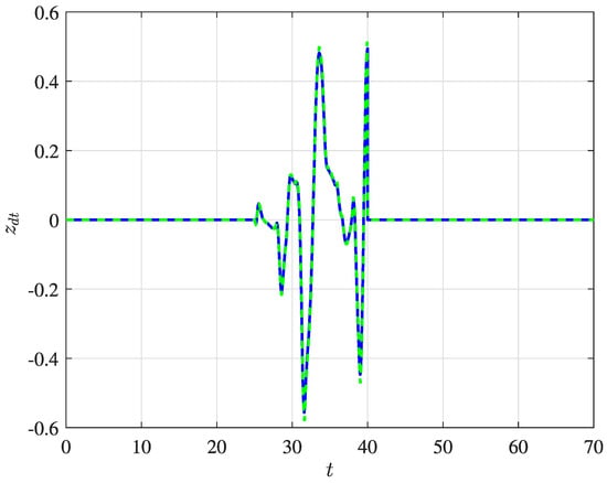
Figure 19.
Estimation of the external disturbance for the vertical position, showing the current (solid blue line) and estimated (dashed green line) profiles.
In this sense, the external disturbance estimation can be further used to calculate the Dryden force, then applied to the controller design to attenuate the undesired vibration.
5. Conclusions
This work describes the dynamics of an unmanned aerial vehicle with 11 degrees of freedom according to the Newton–Euler formulation. The equation of motion considers both the quadrotor and payload dynamics, as well as a combination of elastic and swing load attachments. The proposed dynamics are used to evaluate the payload vibration characteristics in different scenarios and under external disturbances. The effects of rigid and elastic attachments, wind velocity and payload weight on the quadrotor’s flight performance were investigated. In the medical field, some pharmaceutical goods and organs are susceptible to specific frequencies of vibration, meaning an initial evaluation must be performed to verify the feasibility of commercial quadrotors.
Since the addition of the payload adds uncertainties to the system, an adaptive sliding mode control (ASMC) was proposed to compensate for the payload dynamics and controller design. A correcting-factor was calculated based on the sliding surface and quadrotor altitude control law, without the previous knowledge of payload nominal value. In addition, to spread the use of low-cost quadrotors in medical sectors, a reduced-dimension observer of the proposed 11-dof quadrotor was developed to estimate the payload trajectory and external disturbances characteristics. In addition to the advantage of accurately estimating the payload trajectory, the RDO decreases the need for sensors and the overall cost of quadrotors.
The elasticity of an attachment is well known for decreasing the impulsive forces on the payload; however, this can enhance the relative trajectory between the quadrotor and its payload. Two trajectory configurations are used to analyze the payload vibration characteristics. In a circular trajectory, the swing load and its flexible dynamics significantly increase the undesired vibrations, thereby decreasing the system stability and its controller performance.
The root mean square (RMS) method is another technique used to evaluate the vibration characteristics. The RMS of the lateral displacement for the circular trajectory is approximately 5 times higher in comparison to that of the rectangular trajectory. In addition to the payload, the quadrotor trajectory is also impacted according to the wind intensity, with increases of up to 10%. In addition, according to the payload weight and attachment stiffness, different oscillation intensities can be generated.
The recommendations for future work include the inclusion of the estimated external disturbance in the controller design. This analysis can be compared to the traditional references of the SMC, emphasizing the differences in vibration suppression responses and flight performance. In addition, the optimization of the controller by assessing the effects of its sub-parameters might lead to a significant reduction in the undesired vibration.
Author Contributions
Conceptualization, R.S.G. and D.D.B.; methodology, R.S.G. and D.D.B.; project administration, R.S.G., R.M.B. and D.D.B.; writing—original draft, R.S.G.; writing—review and editing, R.M.B. and D.D.B. All authors have read and agreed to the published version of the manuscript.
Funding
The first author gives special thanks to the Brazilian Coordination for the Improvement of Higher Education Personnel (CAPES)—Finance Code 001. The second author acknowledges the support of the NSERC for the Canada Research Chair Holder Tier 1 in Aircraft Modeling and Simulation Technologies Program. The third author would like to thank the National Council for Scientific and Technological Development (CNPq)—Grant No. 429963/2016-5.
Institutional Review Board Statement
Not applicable.
Informed Consent Statement
Not applicable.
Data Availability Statement
Not applicable.
Acknowledgments
The authors would like to give special thanks to São Paulo State University, CAPES, CNPq and École de Technologie Supérieure.
Conflicts of Interest
The authors declare no conflict of interest.
Abbreviations
| UAV | Unmanned Aerial Vehicle |
| GPS | Global Positioning System |
| SMC | Sliding Mode Control |
| GESO | Generalized Extended State Observer |
| UAS | Unmanned Aircraft System |
| IMU | Inertial Measurement Unit |
| DO | Disturbance Observer |
| ESO | Extended State Observer |
| PID | Proportional Integral and Derivative |
| RMS | Root Mean Square |
| LQR | Linear Quadratic Regulator |
Appendix A. Load-Correcting Factor
As represented in Equation (22), the factor is calculated to compensate for the controller performance due to the extra mass added to the quadrotor. Figure A1 shows the estimation of the payload factor during the flight.
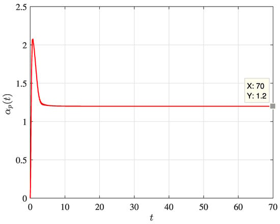
Figure A1.
Estimation of the load-correcting factor over time.
The nominal attached mass corresponds to 20% of the quadrotor weight. It is clear that the factor assumes its real value just a few seconds after the beginning of the flight. The sliding mode control works in two steps: firstly, it guides the convergence to the sliding surface, then maintains the analyzed variable on its surface. Thus, the load-correcting factor reaches its real value when the variables are sliding on the surface, as seen in Figure A1 and Figure A2 (after approximately 7 s). Figure A2 depicts the sliding surface in the vertical direction.
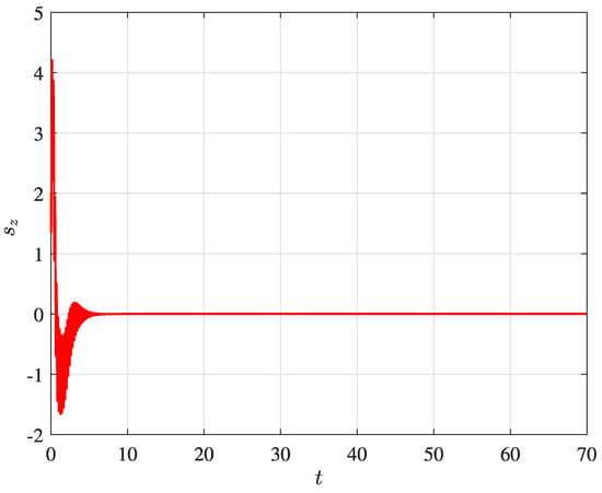
Figure A2.
Sliding surface in the vertical direction.
Therefore, not only is the controller altitude compensated by the coefficient , but the load-correcting factor is also included in the dynamic matrices, since the payload moments of inertia are defined by , as described in Section 2.
Appendix B. Reduced-Dimension Observer Matrices
The matrices used to design the reduced-dimension observer are defined as follows:
where and are expressed as:
and . The term is defined as follows:
In addition, and are represented as:
where and ), such that ). The terms and are defined in Equation (A5):
The linear control torque input matrices are expressed by:
References
- Hii, M.; Courtney, P.; Royall, P. An Evaluation of the Delivery of Medicines Using Drones. Drones 2019, 3, 52. [Google Scholar] [CrossRef]
- Malik, R.; Roy, I. Probing the mechanism of insulin aggregation during agitation. Int. J. Pharm. 2011, 413, 73–80. [Google Scholar] [CrossRef] [PubMed]
- Phan, C.; Liu, H. Dynamic Mapping of Forest Fire Fronts Using Multiple Unmanned Aerial Vehicles. In Proceedings of the AIAA Guidance, Navigation, and Control Conference, Toronto, ON, Canada, 2–5 August 2010. [Google Scholar] [CrossRef]
- Kim, J.; Kim, S.; Ju, C.; Son, H.I. Unmanned Aerial Vehicles in Agriculture: A Review of Perspective of Platform, Control, and Applications. IEEE Access 2019, 7, 105100–105115. [Google Scholar] [CrossRef]
- Lin, Z.; Liu, H.H.T.; Wotton, M. Kalman Filter-Based Large-Scale Wildfire Monitoring with a System of UAVs. IEEE Trans. Ind. Electron. 2018, 66, 606–615. [Google Scholar] [CrossRef]
- Ju, C.; Son, H.I. Multiple UAV Systems for Agricultural Applications: Control, Implementation, and Evaluation. Electronics 2018, 7, 162. [Google Scholar] [CrossRef]
- Segui, M.; Sugar Gabor, O.; Koreanschi, A.; Botez, R.M. Morphing wing application on Hydra Technologies UAS-S4 IASTED Modelling. In Proceedings of the IASTED Modelling, Identification and Control 2017 Conference, Innsbruck, Austria, 20–21 February 2017. [Google Scholar]
- Puri, A. A Survey of Unmanned Aerial Vehicles (UAV) for Traffic Surveillance; Department of Computer Science and Engineering, University of South Florida: Tampa, FL, USA, 2005; pp. 1–29. [Google Scholar]
- Kingston, D.; Rasmussen, S.; Humphrey, L. Automated UAV tasks for search and surveillance. In Proceedings of the 2016 IEEE Conference on Control Applications (CCA), Buenos Aires, Argentina, 19–22 September 2016; pp. 1–8. [Google Scholar] [CrossRef]
- Geronel, R.S.; Bueno, D.D. Trajectory Tracking of a Quadcopter with an Attached Payload Mass under External Disturbances. In Proceedings of the 2021 14th IEEE International Conference on Industry Applications (INDUSCON), São Paulo, Brazil, 15–18 August 2021; pp. 1288–1295. [Google Scholar] [CrossRef]
- Yanez, B.H.; Beltran, C.F.; Tapia, O.R.; Kuitche, M.A.J.; Botez, R.M. Generalized extended state observer based-control for active suppression of forced vibrations in a multi-rotor unmanned vehicle. In Proceedings of the 26th International Congress on Sound and Vibration (ICSV), Montreal, QC, Canada, 7–11 July 2019. [Google Scholar]
- Botez, R.M.; Boustani, I.; Vayani, N. Active Vibration Control for a Flexible Aircraft Equipped with Gust Load Control System. In Proceedings of the 6th International Congress on Sound and Vibration, Copenhagen, Denmark, 5–8 July 1999; pp. 1731–1738. [Google Scholar]
- Scalea, J.R.; Restaino, S.; Scassero, M.; Bartlett, S.T.; Wereley, N. The final frontier? Exploring organ transportation by drone. Am. J. Transplant. 2018, 19, 962–964. [Google Scholar] [CrossRef]
- Oakey, A.; Waters, T.; Zhu, W.; Royall, P.; Cherrett, T.; Courtney, P.; Majoe, D.; Jelev, N. Quantifying the Effects of Vibration on Medicines in Transit Caused by Fixed-Wing and Multi-Copter Drones. Drones 2021, 5, 22. [Google Scholar] [CrossRef]
- Arizaga, J.M.; Castaneda, H.; Castillo, P. Payload Swing Attenuation of a Fully-Actuated Hexacopter via Extended High Gain Observer Based Adaptive Sliding Control. In Proceedings of the 2021 International Conference on Unmanned Aircraft Systems (ICUAS), Athens, Greece, 15–18 June 2021; pp. 901–908. [Google Scholar] [CrossRef]
- Carbaja, F.B.; Badillo, H.Y.; Olvera, R.T.; Contreras, A.F.; Gonzalez, A.V.; Garcia, I.L. On Active Vibration Absorption in Motion Control of a Quadrotor UAV. Mathematics 2022, 10, 235. [Google Scholar]
- Alkomy, H.; Shan, J. Vibration reduction of a quadrotor with a cable-suspended payload using polynomial trajectories. Nonlinear Dyn. 2021, 104, 3713–3735. [Google Scholar] [CrossRef]
- Ullah, N.; Sami, I.; Shaoping, W.; Mukhtar, H.; Wang, X.; Chowdhury, M.S.; Techato, K. A computationally efficient adaptive robust control scheme for a quad-rotor transporting cable-suspended payloads. Proc. Inst. Mech. Eng. Part G J. Aerosp. Eng. 2022, 236, 379–395. [Google Scholar] [CrossRef]
- Bingöl, O.; Güzey, H.M. Neuro sliding mode control of quadrotor UAVs carrying suspended payload. Adv. Robot. 2021, 35, 255–266. [Google Scholar] [CrossRef]
- Pizetta, I.H.B.; Brandao, A.S.; Sarcinelli-Filho, M. Modelling and control of a PVTOL quadrotor carrying a suspended load. In Proceedings of the 2015 International Conference on Unmanned Aircraft Systems, ICUAS, Denver, CO, USA, 9–12 June 2015; pp. 444–450. [Google Scholar]
- Zhou, X.; Liu, R.; Zhang, J.; Zhang, X. Stabilization of a Quadrotor with Uncertain Suspended Load Using Sliding Mode Control. In Proceedings of the ASME 2016 International Design Engineering Technical Conferences and Computers and Information in Engineering Conference, Charlotte, NC, USA, 21–24 August 2016. [Google Scholar] [CrossRef]
- Pounds, P.E.I.; Bersak, D.R.; Dollar, A.M. Stability of small scale UAV helicopters and quadrotors with added payload mass under PID control. Auto. Robots 2012, 33, 129–142. [Google Scholar] [CrossRef]
- Kusznir, T.; Smoczek, J. Sliding Mode-Based Control of a UAV Quadrotor for Suppressing the Cable-Suspended Payload Vibration. J. Control Sci. Eng. 2020, 2020, 5058039. [Google Scholar] [CrossRef]
- Guerrero-Sánchez, M.; Lozano, R.; Castillo, P.; Hernández-González, O.; García-Beltrán, C.; Valencia-Palomo, G. Nonlinear control strategies for a UAV carrying a load with swing attenuation. Appl. Math. Model. 2020, 91, 709–722. [Google Scholar] [CrossRef]
- Klausen, K.; Fossen, T.I.; Johansen, T.A. Nonlinear Control with Swing Damping of a Multirotor UAV with Suspended Load. J. Intell. Robot. Syst. 2017, 88, 379–394. [Google Scholar] [CrossRef]
- Palunko, I.; Fierro, R.; Cruz, P. Trajectory generation for swing-free maneuvers of a quadrotor with suspended payload: A dynamic programming approach. In Proceedings of the 2012 IEEE International Conference on Robotics and Automation, Saint Paul, MN, USA, 14–18 May 2012; pp. 2691–2697. [Google Scholar] [CrossRef]
- Klausen, K.; Fossen, T.I.; Johansen, T. Nonlinear Control of a Multirotor UAV with Suspended Load. In Proceedings of the 2015 International Conference on Unmanned Aircraft Systems (ICUAS), Denver, CO, USA, 9–12 June 2015; pp. 1–9. [Google Scholar]
- Wu, Y.; Xie, Y.; Li, S. Parameter Adaptive Control for a Quadrotor with a Suspended Unknown Payload under External Disturbance. IEEE Access 2021, 9, 139958–139967. [Google Scholar] [CrossRef]
- Patron, R.F.; Kessaci, A.; Botez, R. Flight trajectories optimization under the influence of winds using genetic algorithms. In Proceedings of the ASME 2014 International Mechanical Engineering Congress and Exposition, Montreal, QC, Canada, 14–20 November 2014. [Google Scholar] [CrossRef]
- Badillo, H.Y.; Botez, R.M. Disturbance Rejection in Longitudinal Control for the UAS-S4 Ehecatl Design. In Proceedings of the AIAA Aviation 2020 Forum, Virtual Event, 15–19 June 2020. [Google Scholar]
- Kuitche, M.A.; Botez, R.M.; Guillemin, A.; Communier, D. Aerodynamic Modeling of Unmanned Aerial System through Nonlinear Vortex Lattice Method, Computational Fluid Dynamics and Experimental Validation—Application to the UAS-S45 Bzlaam: Part 1. INCAS Bull. 2020, 12, 91–103. [Google Scholar] [CrossRef]
- Kuitche, M.A.; Botez, R.M.; Guillemin, A.; Communier, D. Aerodynamic Modeling of Unmanned Aerial System through Nonlinear Vortex Lattice Method, Computational Fluid Dynamics and Experimental Validation—Application to the UAS-S45 Bzlaam: Part 2. INCAS Bull. 2020, 12, 99–115. [Google Scholar] [CrossRef]
- Gabor, O.; Koreanschi, A.; Botez, R. Analysis of UAS-S4 Éhecatl aerodynamic performance improvement using several configurations of a morphing wing technology. Aeronaut. J. 2016, 120, 1337–1364. [Google Scholar] [CrossRef]
- Tondji, Y.; Botez, R.M. Semi-empirical estimation and experimental method for determining inertial properties of the Unmanned Aerial System—UAS-S4 of Hydra Technologies. Aeronaut. J. 2017, 121, 1648–1682. [Google Scholar] [CrossRef]
- Gabor, O.S.; Simon, A.; Koreanschi, A.; Botez, R.M. Aerodynamic performance improvement of the UAS-S4 Éhecatl morphing airfoil using novel optimization techniques. Proc. Inst. Mech. Eng. Part G J. Aerosp. Eng. 2015, 230, 1164–1180. [Google Scholar] [CrossRef]
- Botez, R.M. Morphing Wing, UAV and Aircraft Multidisciplinary Studies at the Laboratory of Applied Research in Active Controls, Avionics and AeroServoElasticity LARCASE. Aerosp. J. 2018, 14, 1–11. [Google Scholar]
- Wang, B.; Yu, X.; Mu, L.; Zhang, Y. Disturbance observer-based adaptive fault-tolerant control for a quadrotor helicopter subject to parametric uncertainties and external disturbances. Mech. Syst. Signal Process. 2018, 120, 727–743. [Google Scholar] [CrossRef]
- Fan, J.; Zhang, Y.; Zheng, Z. Adaptive Observer-Based Integrated Fault Diagnosis and Fault-Tolerant Control Systems against Actuator Faults and Saturation. J. Dyn. Syst. Meas. Control 2013, 135, 041008. [Google Scholar] [CrossRef]
- Guo, K.; Jia, J.; Yu, X.; Guo, L.; Xie, L. Multiple observers based anti-disturbance control for a quadrotor UAV against payload and wind disturbances. Control Eng. Pract. 2020, 102, 104560. [Google Scholar] [CrossRef]
- Cestino, E.; Frulla, G.; Marzocca, P. A Reduced Order Model for the Aeroelastic Analysis of Flexible Wings. SAE Int. J. Aerosp. 2013, 6, 447–458. [Google Scholar] [CrossRef]
- Cassaro, M.; Battipede, M.; Marzocca, P.; Cestino, E.; Behal, A. 1 Adaptive Flutter Suppression Control Strategy for Highly Flexible Structure. SAE Int. J. Aerosp. 2013, 6, 693–702. [Google Scholar] [CrossRef]
- Findlay, E.; Forbes, J.; Liu, H.; de Ruiter, A.; Damaren, C.; Lee, J. Investigation of Active Vibration Suppression of a Flexible Satellite using Magnetic Attitude Control. In Proceedings of the AIAA Guidance, Navigation, and Control Conference, Portland, OR, USA, 8–11 August 2011. [Google Scholar] [CrossRef][Green Version]
- Haghighat, S.; Liu, H.H.T.; Martins, J. Model-Predictive Gust Load Alleviation Controller for a Highly Flexible Aircraft. J. Guid. Control. Dyn. 2012, 35, 1751–1766. [Google Scholar] [CrossRef]
- Tuzcu, I.; Marzocca, P.; Cestino, E.; Romeo, G.; Frulla, G. Stability and Control of a High-Altitude, Long-Endurance UAV. J. Guid. Control. Dyn. 2007, 30, 713–721. [Google Scholar] [CrossRef]
- Estevez, J.; Lopez-Guede, J.; Garate, G.; Graña, M. A Hybrid Control Approach for the Swing Free Transportation of a Double Pendulum with a Quadrotor. Appl. Sci. 2021, 11, 5487. [Google Scholar] [CrossRef]
- Beal, T.R. Digital simulation of atmospheric turbulence for Dryden and von Karman models. J. Guid. Control. Dyn. 1993, 16, 132–138. [Google Scholar] [CrossRef]
- Utkin, V.I. Sliding Modes in Control and Optimization; Springer: Berlin/Heidelberg, Germany, 1992. [Google Scholar] [CrossRef]
- Zheng, E.-H.; Xiong, J.-J.; Luo, J.-L. Second order sliding mode control for a quadrotor UAV. ISA Trans. 2014, 53, 1350–1356. [Google Scholar] [CrossRef] [PubMed]
- Zhong, Y.; Zhang, Y.; Zhang, W.; Zuo, J.; Zhan, H. Robust Actuator Fault Detection and Diagnosis for a Quadrotor UAV with External Disturbances. IEEE Access 2018, 6, 48169–48180. [Google Scholar] [CrossRef]
- Vahdanipour, M.; Khodabandeh, M. Adaptive fractional order sliding mode control for a quadrotor with a varying load. Aerosp. Sci. Technol. 2019, 86, 737–747. [Google Scholar] [CrossRef]
- Yuan, X.; Ren, X.; Zhu, B.; Zheng, Z.; Zuo, Z. Robust H∞ Control for Hovering of a Quadrotor UAV with Slung Load. In Proceedings of the 12th Asian Control Conference (ASCC), Kitakyushu, Japan, 9–12 June 2019; pp. 1–6. [Google Scholar]
- Luenberger, D. An introduction to observers. IEEE Trans. Autom. Control 1971, 16, 596–602. [Google Scholar] [CrossRef]
- Ogata, K.; Brewer, J.W. Modern Control Engineering; Pearson: London, UK, 2010. [Google Scholar]
- Faust, A.; Palunko, I.; Cruz, P.; Fierro, R.; Tapia, L. Learning swing-free trajectories for UAVs with a suspended load. In Proceedings of the 2013 IEEE International Conference on Robotics and Automation, Karlsruhe, Germany, 6–10 May 2013; pp. 4902–4909. [Google Scholar] [CrossRef]
- Barikbin, B.; Fakharian, A. Trajectory tracking for quadrotor UAV transporting cable-suspended payload in wind presence. Trans. Inst. Meas. Control 2018, 41, 1243–1255. [Google Scholar] [CrossRef]
- Shiang, W.J.; Cannon, D.; Gorman, J. Optimal Force Distributbion Applied to a Robotic Crane with Flexible Cables. In Proceedings of the 2000 ICRA. Millennium Conference, IEEE International Conference on Robotics and Automation, Symposia Proceedings (Cat. No.00CH37065), San Francisco, CA, USA, 24–28 April 2020; Volume 2, pp. 1948–1954. [Google Scholar]
- Fatehi, M.H.; Eghtesad, M.; Amjadifard, R. Modelling and Control of an Overhead Crane System with a Flexible Cable and Large Swing Angle. J. Low Freq. Noise Vib. Act. Control 2014, 33, 395–409. [Google Scholar] [CrossRef]
- Kotaru, P.; Wu, G.; Sreenath, K. Dynamics and control of a quadrotor with a payload suspended through an elastic cable. In Proceedings of the 2017 American Control Conference (ACC), Seattle, WA, USA, 24–26 May 2017; pp. 3906–3913. [Google Scholar] [CrossRef]
- Scalea, J.R.; Restaino, S.; Scassero, M.; Blankenship, G.; Bartlett, S.T.; Wereley, N. An Initial Investigation of Unmanned Aircraft Systems (UAS) and Real-Time Organ Status Measurement for Transporting Human Organs. IEEE J. Transl. Eng. Health Med. 2018, 6, 1–7. [Google Scholar] [CrossRef]
- Geronel, R.S.; Dowell, E.H.; Bueno, D.D. Estimating the oscillation frequency of a payload mass on quadcopter in non-autonomous flight. J. Vib. Control 2021, 2021, 1–15. [Google Scholar] [CrossRef]
Publisher’s Note: MDPI stays neutral with regard to jurisdictional claims in published maps and institutional affiliations. |
© 2022 by the authors. Licensee MDPI, Basel, Switzerland. This article is an open access article distributed under the terms and conditions of the Creative Commons Attribution (CC BY) license (https://creativecommons.org/licenses/by/4.0/).