
A Developed Plasmatron Design to Enhance Production of Hydrogen in Synthesis Gas Produced by a Fuel Reformer System

 ,
,  , ,
, ,
Abstract
:1. Introduction
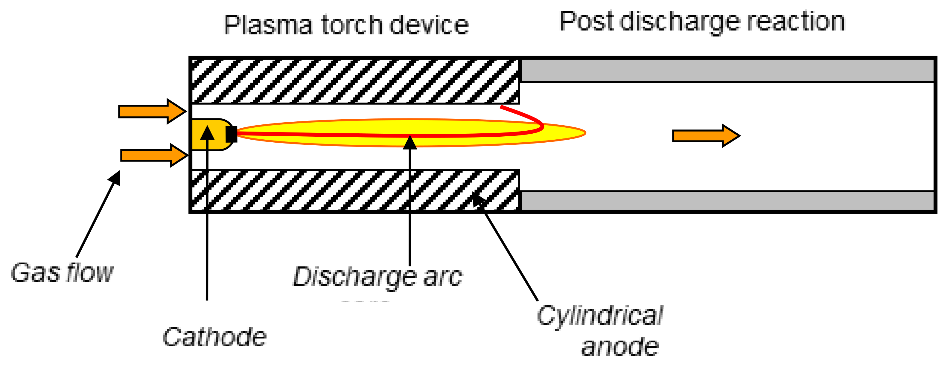
2. Materials and Methods
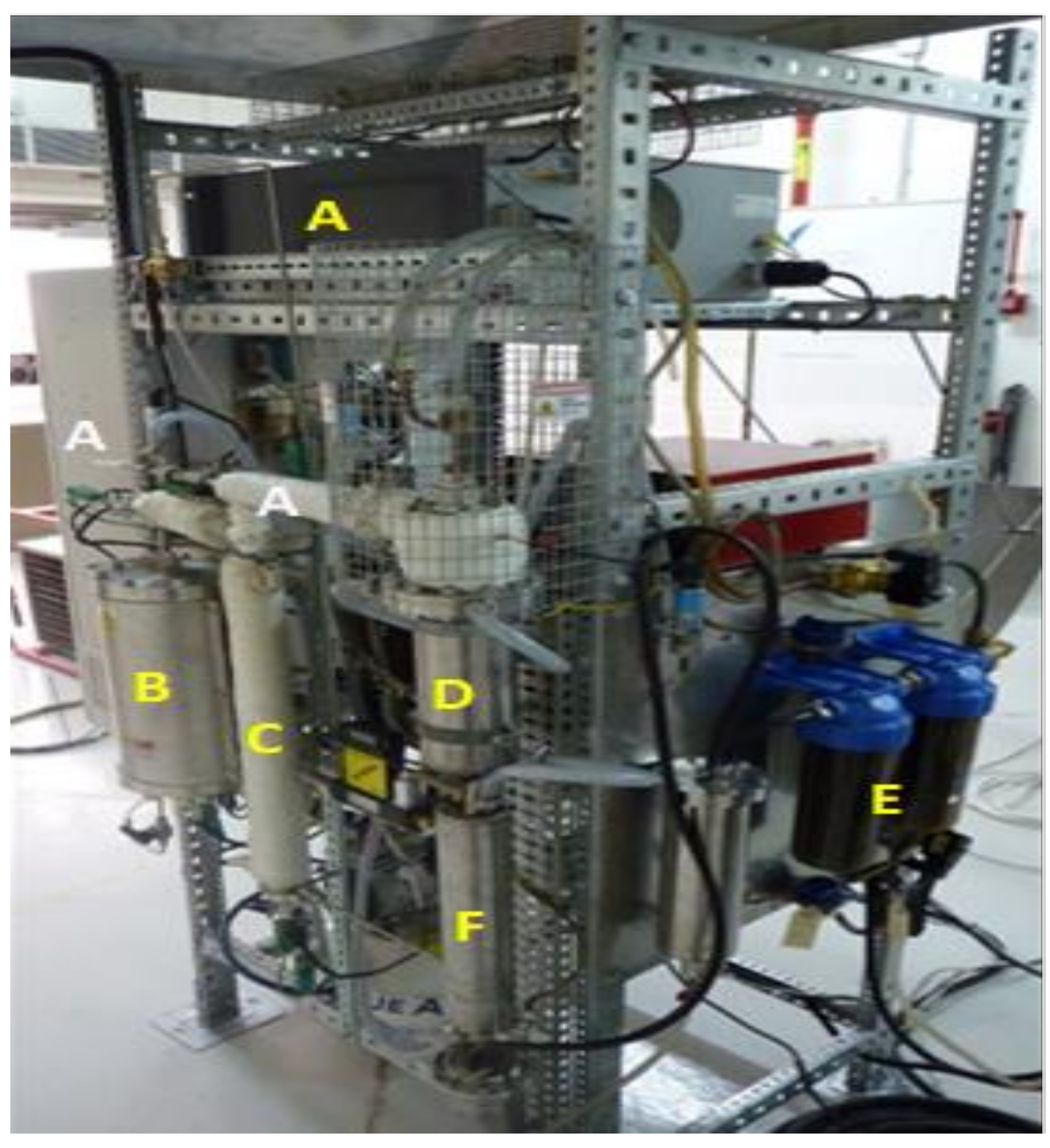
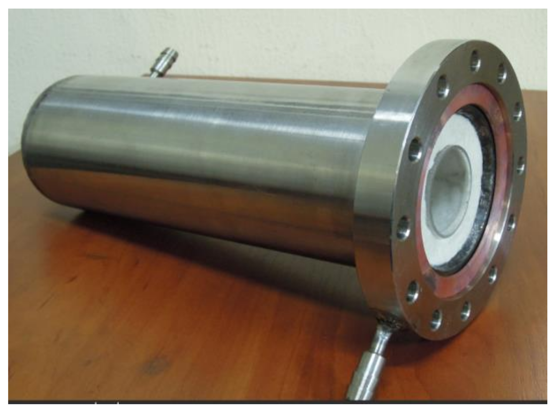
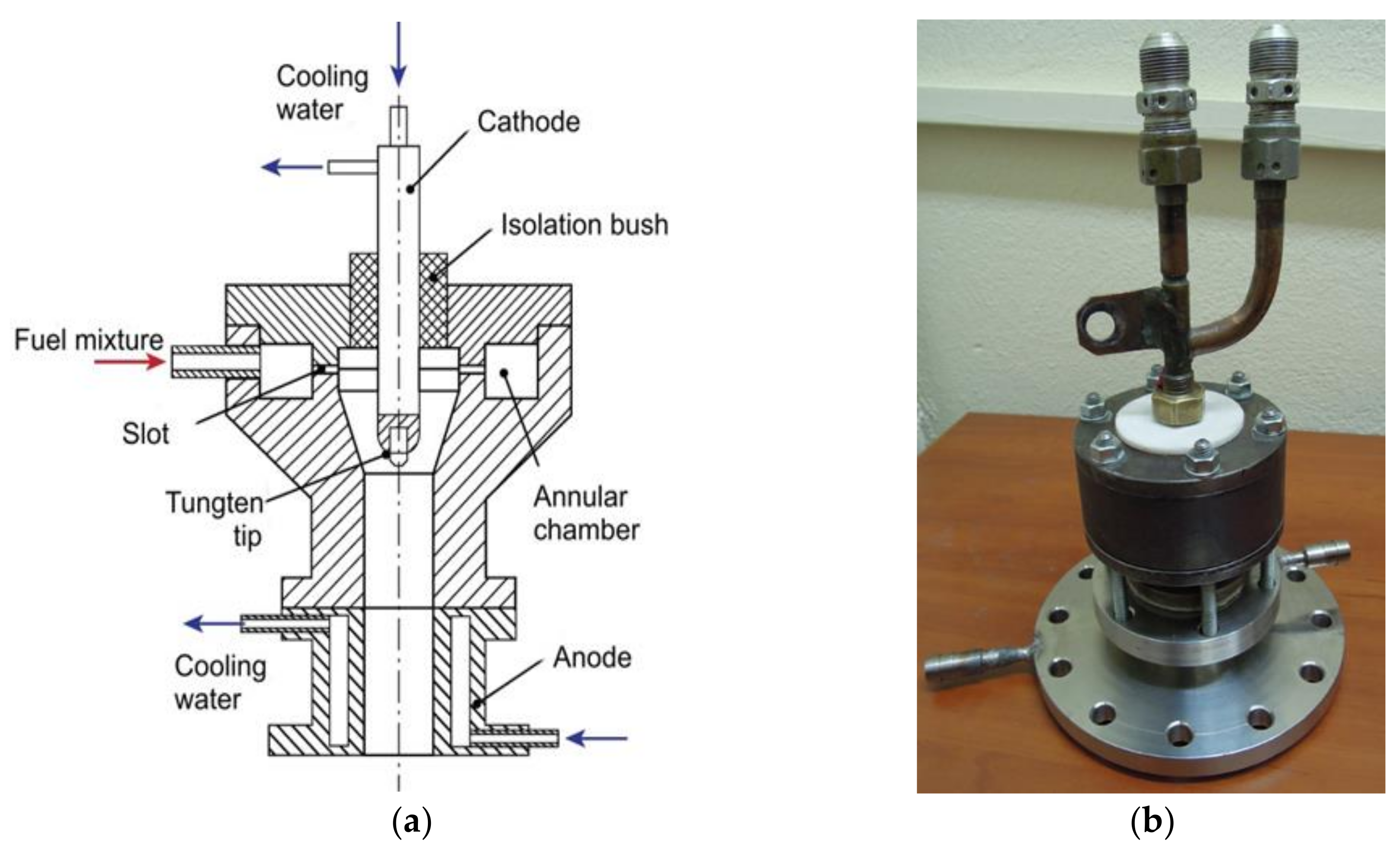
2.1. Experimental Setup
2.2. Experimental Procedure
3. Results and Discussion
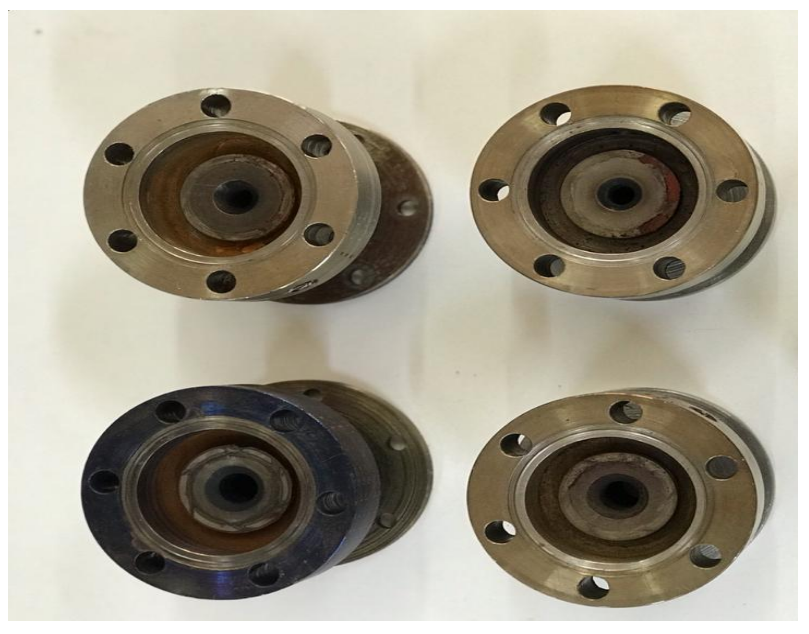
3.1. Cathode Tip Erosion under Fuel Reforming Conditions
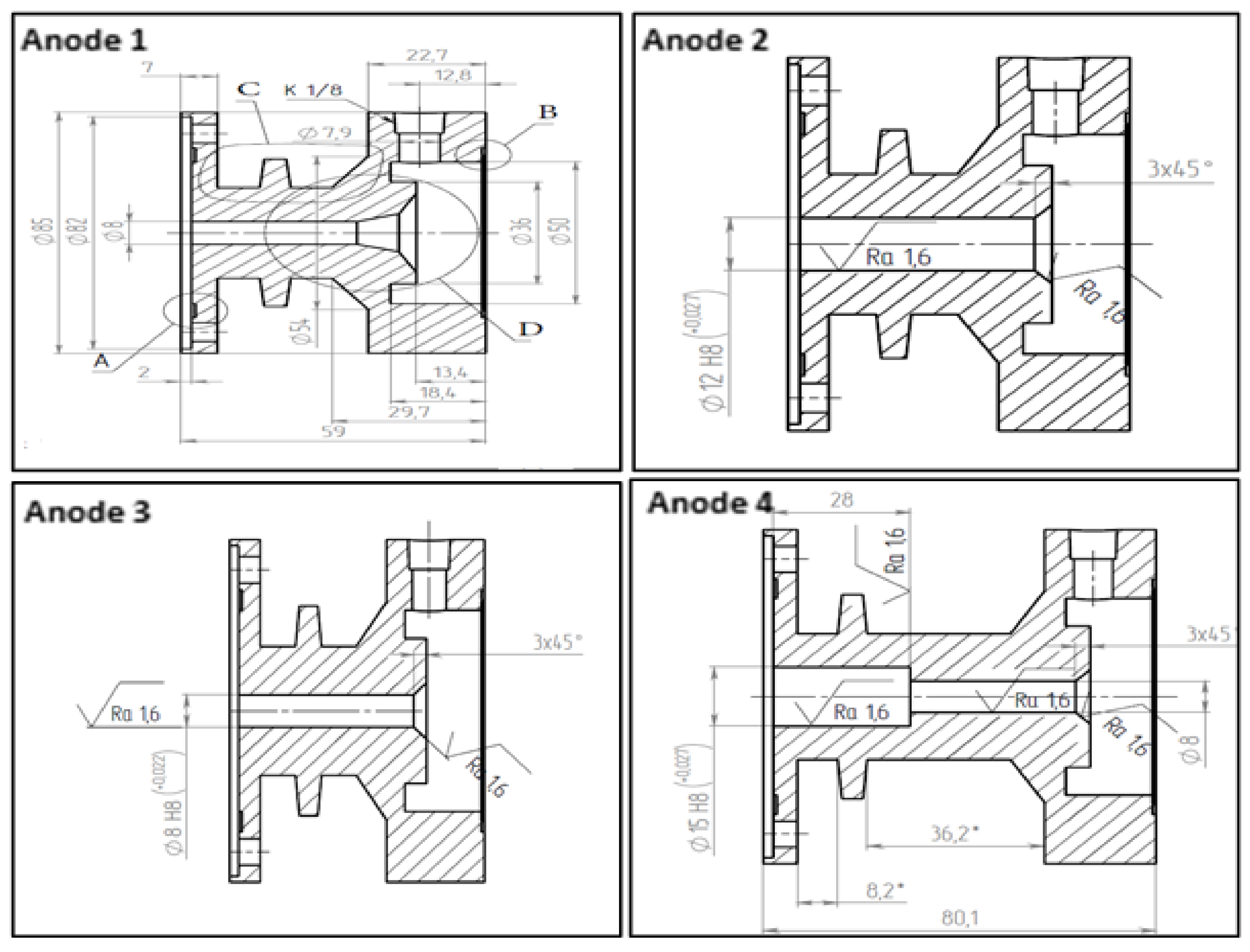
3.2. Anode Design and Fuel Reforming Performance
4. Conclusions
Author Contributions
Funding
Institutional Review Board Statement
Informed Consent Statement
Data Availability Statement
Acknowledgments
Conflicts of Interest
Abbreviations
| APU | auxiliary power unit |
| POX | partial oxidation |
| SI | spark ignition |
| SR | steam reforming |
| NOx | nitrogen oxides |
| ATR | autothermal reforming |
| CnHm | hydrocarbons |
| CO | carbon monoxide |
| CO2 | carbon dioxide |
| AFR | air/fuel mass ratio |
References
- Conte, E.; Boulouchos, K. Influence of Hydrogen-Rich-Gas Addition on Combustion, Pollutant Formation and Efficiency of an IC-SI Engine; SAE Technical Paper Series; SAE International: Warrendale, PE, USA, 2004. [Google Scholar] [CrossRef]
- Tully, E.J.; Heywood, J.B. Lean-Burn Characteristics of a Gasoline Engine Enriched with Hydrogen Plasmatron Fuel Reformer; SAE Technical Paper Series; SAE International: Warrendale, PE, USA, 2003. [Google Scholar] [CrossRef] [Green Version]
- Quader, A.A.; Kirwan, J.E.; Grieve, M.J. Engine Performance and Emissions near the Dilute Limit with Hydrogen Enrichment Using an On-Board Reforming Strategy; SAE Technical Paper Series; SAE International: Warrendale, PE, USA, 2003. [Google Scholar] [CrossRef]
- Sobyanin, V.; Sadykov, V.; Kirillov, V.; Kuzmin, V.; Kuzin, N.; Vostrikov, Z.; Smirnov, E.; Sorokin, A.; Brizitskiy, O.; Terentyev, V.; et al. Syngas as a fuel for IC and diesel engines: Efficiency and harmful emissions cut off. In Proceedings of the International Hydrogen Energy Congress and Exhibition, Istanbul, Turkey, 13–15 July 2005. [Google Scholar]
- Kirwan, J.; Quader, A.; Grieve, M. Advanced Engine Management Using On-Board Gasoline Partial Oxidation Reforming for Meeting Super-ULEV (SULEV) Emissions Standards; SAE Technical Paper 1999-01-2927; SAE International: Warrendale, PE, USA, 1999. [Google Scholar] [CrossRef]
- Lindstrom, B.; Karlsson, J.; Ekdunge, P.; De Verdier, L.; Häggendal, B.; Dawody, J.; Nilsson, M.; Pettersson, L. Diesel fuel reformer for automotive fuel cell applications. Int. J. Hydrog. Energy 2009, 34, 3367–3381. [Google Scholar] [CrossRef]
- Bromberg, L.; Cohn, D.R.; Rabinovich, A.; Heywood, J. Emissions reductions using hydrogen from plasmatron fuel converters. Int. J. Hydrog. Energy 2001, 26, 1115–1121. [Google Scholar] [CrossRef] [Green Version]
- Samsun, R.C.; Prawitz, M.; Tschauder, A.; Pasel, J.; Pfeifer, P.; Peters, R.; Stolten, D. An integrated diesel fuel processing system with thermal start-up for fuel cells. Appl. Energy 2018, 226, 145–159. [Google Scholar] [CrossRef]
- Kang, I.; Bae, J. Autothermal reforming study of diesel for fuel cell application. J. Power Sources 2006, 159, 1283–1290. [Google Scholar] [CrossRef]
- Bensaid, S.; Specchia, S.; Federici, F.; Saracco, G.; Specchia, V. MCFC-based marine APU: Comparison between conventional ATR and cracking coupled with SR integrated inside the stack pressurized vessel. Int. J. Hydrog. Energy 2009, 34, 2026–2042. [Google Scholar] [CrossRef]
- Bromberg, L.; Cohn, D.R.; Rabinovich, A.; Alexeev, N. Hydrogen Manufacturing Using Low Current, Non-Thermal Plasma Boosted Fuel Converters. In Proceedings of the Symposium on Energy for the 21st Century: Hydrogen Energy; Report No. PSFC/RR-01-1; The Fuel Chemistry Division of the American Chemical Society: San Diego, CA, USA, 2001. [Google Scholar]
- Yoon, S.; Kang, I.; Bae, J. Effects of ethylene on carbon formation in diesel autothermal reforming. Int. J. Hydrog. Energy 2008, 33, 4780–4788. [Google Scholar] [CrossRef]
- Bromberg, L.; Cohn, D.R.; Rabinovich, A.; Alexeev, N.; Samokhin, A.; Hadidi, K.; Palaia, J.; Margarit-Bel, N. Onboard Plasmatron Hydrogen Production for Improved Vehicles; PSFC JA-06-3; MIT Plasma Science and Fusion Center: Cambridge, MA, USA, 2006. [Google Scholar]
- Kim, T.-S.; Song, S.; Chun, K.-M.; Lee, S.H. An experimental study of syn-gas production via microwave plasma reforming of methane, iso-octane and gasoline. Energy 2010, 35, 2734–2743. [Google Scholar] [CrossRef]
- Darmon, A.; Rollier, J.D.; Duval, E.; Gonzalez-Aguilar, J.; Metkemeijer, R.; Fulcheri, L. Plasma assisted fuel reforming for on-board hydrogen rich gas production. In Proceedings of the 16th World Hydrogen Energy Conference, Lyon, France, 13–16 June 2006. [Google Scholar]
- Rollier, J.-D.; Gonzalez-Aguilar, J.; Petitpas, G.; Darmon, A.; Fulcheri, L.; Metkemeijer, R. Experimental Study on Gasoline Reforming Assisted by Nonthermal Arc Discharge. Energy Fuels 2007, 22, 556–560. [Google Scholar] [CrossRef]
- Piavis, W.; Turn, S.; Ali Mousavi, S.M. Non-thermal gliding-arc plasma reforming of dodecane and hydroprocessed renewable diesel. Int. J. Hydrog. Energy 2015, 40, 13295–13305. [Google Scholar] [CrossRef] [Green Version]
- Hartvigsen, J.; Hartvigsen, J.; Elangovan, S.; Hollist, M.; Czernichowski, P.; Frost, L. Non-Thermal Plasma Reformation of Liquid Fuels. ECS Trans. 2011, 35, 2825–2833. [Google Scholar] [CrossRef]
- Paulmier, T.; Fulcheri, L. Use of non-thermal plasma for hydrocarbon reforming. Chem. Eng. J. 2005, 106, 59–71. [Google Scholar] [CrossRef]
- Sobacchi, M.G.; Saveliev, A.V.; Fridman, A.A.; Kennedy, L.A.; Ahmed, S.; Krause, T. Experimental assessment of a combined plasma/catalytic system for hydrogen production via partial oxidation of hydrocarbon fuels. Int. J. Hydrog. Energy 2002, 27, 635–642. [Google Scholar] [CrossRef]
- Czylkowski, D.; Hrycak, B.; Miotk, R.; Jasiński, M.; Mizeraczyk, J.; Dors, M. Microwave plasma for hydrogen production from liquids. Nukleonika 2016, 61, 185–190. [Google Scholar] [CrossRef] [Green Version]
- Malik, M.A.; Hughes, D.; Malik, A.; Xiao, S.; Schoenbach, K.H. Study of the Production of Hydrogen and Light Hydrocarbons by Spark Discharges in Diesel, Kerosene, Gasoline, and Methane. Plasma Chem. Plasma Process. 2012, 33, 271–279. [Google Scholar] [CrossRef]
- Gallagher, M.J.; Geiger, R.; Polevich, A.; Rabinovich, A.; Gutsol, A.; Fridman, A. On-board plasma-assisted conversion of heavy hydrocarbons into synthesis gas. Fuel 2010, 89, 1187–1192. [Google Scholar] [CrossRef]
- Mechtly, E. Properties of Materials. In Reference Data for Engineers: Radio, Electronics, Computer, and Communications; Van Valkenburg, M.E., Middleton, W.M., Eds.; Elsevier: Amsterdam, The Netherlands, 2002. [Google Scholar] [CrossRef]
- Lee, D.H.; Kim, K.-T.; Song, Y.-H.; Kang, W.S.; Jo, S. Mapping Plasma Chemistry in Hydrocarbon Fuel Processing Processes. Plasma Chem. Plasma Process. 2013, 33, 249–269. [Google Scholar] [CrossRef]
- Gutsol, A. Warm discharges for fuel conversion. In Handbook of Combustion; New technologies; Lackner, M., Winter, F., Agarwal, A.K., Eds.; Wiley-VCH: Weinheim, Germany, 2010; Volume 5, pp. 323–353. [Google Scholar]
- Benilov, M.; Naidis, G. Modeling of hydrogen-rich gas production by plasma reforming of hydrocarbon fuels. Int. J. Hydrog. Energy 2006, 31, 769–774. [Google Scholar] [CrossRef]
- Benilov, M.; Naidis, G. Modelling of low-current discharges in atmospheric-pressure air taking account of non-equilibrium effects. J. Phys. D Appl. Phys. 2003, 36, 1834–1841. [Google Scholar] [CrossRef] [Green Version]
- Lebouvier, A.; Delalondre, C.; Fresnet, F.; Boch, V.; Rohani, V.-J.; Cauneau, F.; Fulcheri, L. Three-Dimensional Unsteady MHD Modeling of a Low-Current High-Voltage Nontransferred DC Plasma Torch Operating with Air. IEEE Trans. Plasma Sci. 2011, 39, 1889–1899. [Google Scholar] [CrossRef] [Green Version]
- Lee, D.H.; Kim, K.-T.; Cha, M.S.; Song, Y.-H. Plasma-controlled chemistry in plasma reforming of methane. Int. J. Hydrog. Energy 2010, 35, 10967–10976. [Google Scholar] [CrossRef]
- Dinh, D.K.; Lee, D.H.; Song, Y.-H.; Jo, S.; Kim, K.-T. Arc length control for efficiency enhancement of energy usage in plasma dry reforming process. J. CO2 Util. 2018, 28, 274–282. [Google Scholar] [CrossRef]
- Lebouvier, A.; Delalondre, C.; Fresnet, F.; Cauneau, F.; Fulcheri, L. 3D MHD modelling of low current–high voltage dc plasma torch under restrike mode. J. Phys. D Appl. Phys. 2011, 45, 25204–25212. [Google Scholar] [CrossRef] [Green Version]
- Cao, X.; Yu, D.; Xiao, M.; Miao, J.; Xiang, Y.; Yao, J. Design and Characteristics of a Laminar Plasma Torch for Materials Processing. Plasma Chem. Plasma Process. 2015, 36, 693–710. [Google Scholar] [CrossRef]
- Fulcheri, L.; Rollier, J.-D.; Gonzalez-Aguilar, J. Design and electrical charaterization of a low current–high voltage compact arc plasma torch. Plasma Sources Sci. Technol. 2006, 16, 183–192. [Google Scholar] [CrossRef]
- Essiptchouk, A. Influence of inlet conditions on vortex characteristics. J. Eng. Phys. Thermophys. 2011, 84, 1126–1131. [Google Scholar] [CrossRef]
- Alharbi, A.A.; Alenazey, F.S.; Migoun, A.N.; Dmitrenko, Y.M.; Zhdanok, S.A. Reducing Pollution Emissions by Adding Syngas Generated by a Plasma-Assisted Gasoline Converter in the Intake Manifold of a Gasoline Engine with Electronic Fuel Injection System. Heat Transf. Res. 2016, 47, 1073–1082. [Google Scholar] [CrossRef]
- Alharbi, A.A.; Binjuwair, S.A.; Alshunaifi, I.A.; Alkhedhair, A.M.; Alabduly, A.J.; Almorat, M.S.; Albishi, M.S. NOx Emission Reduction Using Hydrous Ethanol-Gasoline Blend with Syngas in SI Engine. J. Environ. Prot. 2019, 10, 1278–1298. [Google Scholar] [CrossRef] [Green Version]
- Alharbi, A.A.; Alenazey, F.S.; Binjuwair, S.A.; Alshunaifi, I.A.; Alkhedhair, A.M.; Alabduly, A.J.; Almorat, M.S.; Albishi, M.S. Effect of adding hydrogen-rich synthesis gas and ethanol on NOx emissions with gasoline at different air/fuel mixtures. J. Eng. Res. 2020, 8, 1–16. [Google Scholar] [CrossRef]
- Alharbi, A.A.; Alabduly, A.J.; Alkhedhair, A.M.; Alqahtani, N.B.; Albishi, M.S. Effect of operation under lean conditions on NOx emissions and fuel consumption fueling an SI engine with hydrous ethanol–gasoline blends enhanced with synthesis gas. Energy 2022, 238, 121694. [Google Scholar]
- Ghorui, S.; Meher, K.C.; Kar, R.; Tiwari, N.; Sahasrabudhe, S.N. Unique erosion features of hafnium cathode in atmospheric pressure arcs of air, nitrogen and oxygen. J. Phys. D Appl. Phys. 2016, 49, 295201. [Google Scholar] [CrossRef]
- Alenazey, F.S.; Al-Harbi, A.A.; Chernukho, A.P.; Dmitrenko, Y.M.; Migoun, A.N.; Zhdanok, S.A. Syngas Production from Propane− Butane Mixtures Using a High-Voltage Atmospheric Pressure Discharge Plasma. Heat Transf. Res. 2016, 47, 1057–1072. [Google Scholar] [CrossRef]
- Papagiannakis, R.G.; Rakopoulos, C.D.; Hountalas, D.T.; Giakoumis, E.G. Study of the performance and exhaust emissions of a spark-ignited engine operating on syngas fuel. Int. J. Altern. Propuls. 2007, 1, 190–215. [Google Scholar] [CrossRef]
- Alabduly, A.; Christensen, P.; Harvey, A. The characterization of a packed bed plasma reactor for ozone generation. Plasma Sources Sci. Technol. 2020, 29, 035002. [Google Scholar]


| Experiment | Anode | Gas Ring (Ring 1) and (Ring 2) | Air Flow (g/min) | Fuel Flow (g/min) | AFR |
|---|---|---|---|---|---|
| 1 | 1 | 1 | 24 27 30 | 4 4.5 5 | 6 |
| 2 | |||||
| 2 | 2 | 1 | |||
| 2 | |||||
| 3 | 3 | 1 | |||
| 2 | |||||
| 4 | 4 | 1 | |||
| 2 |
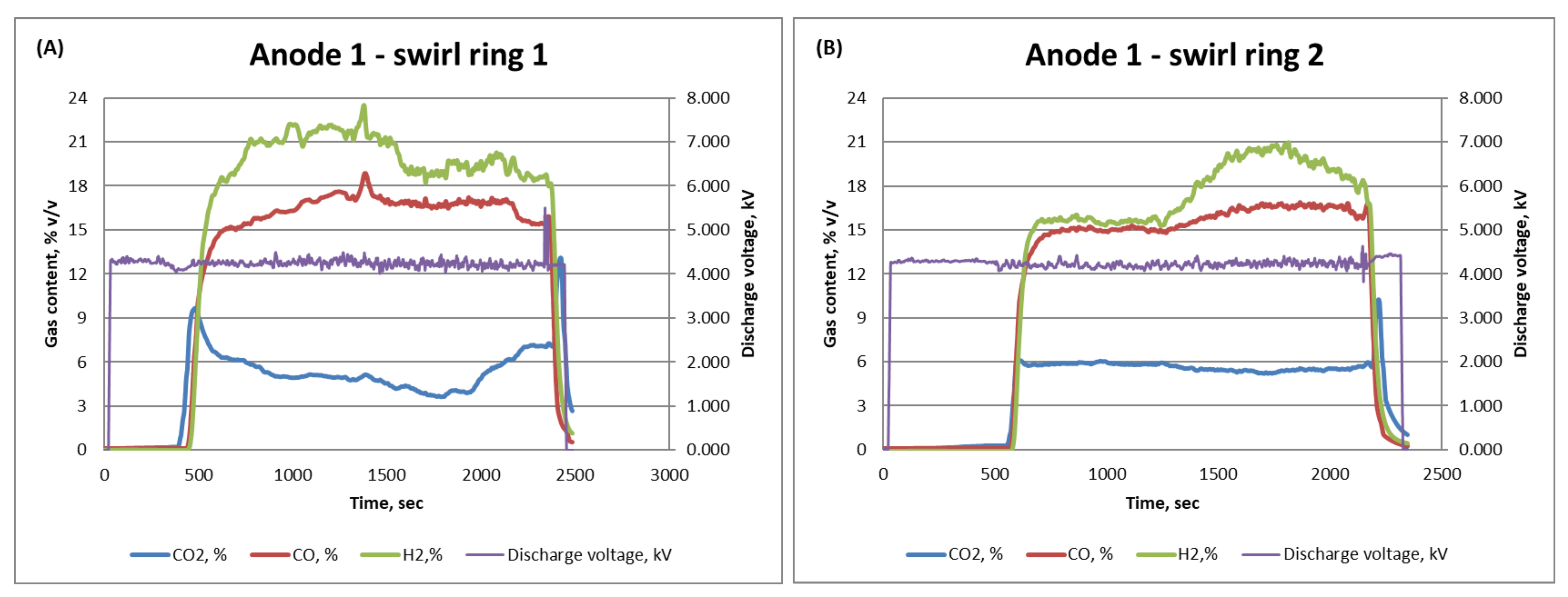
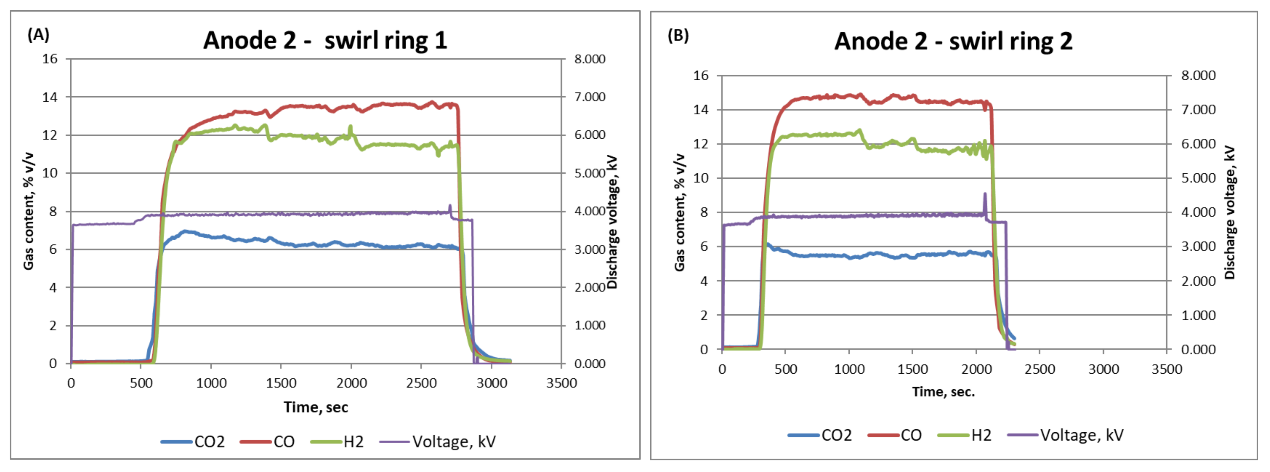
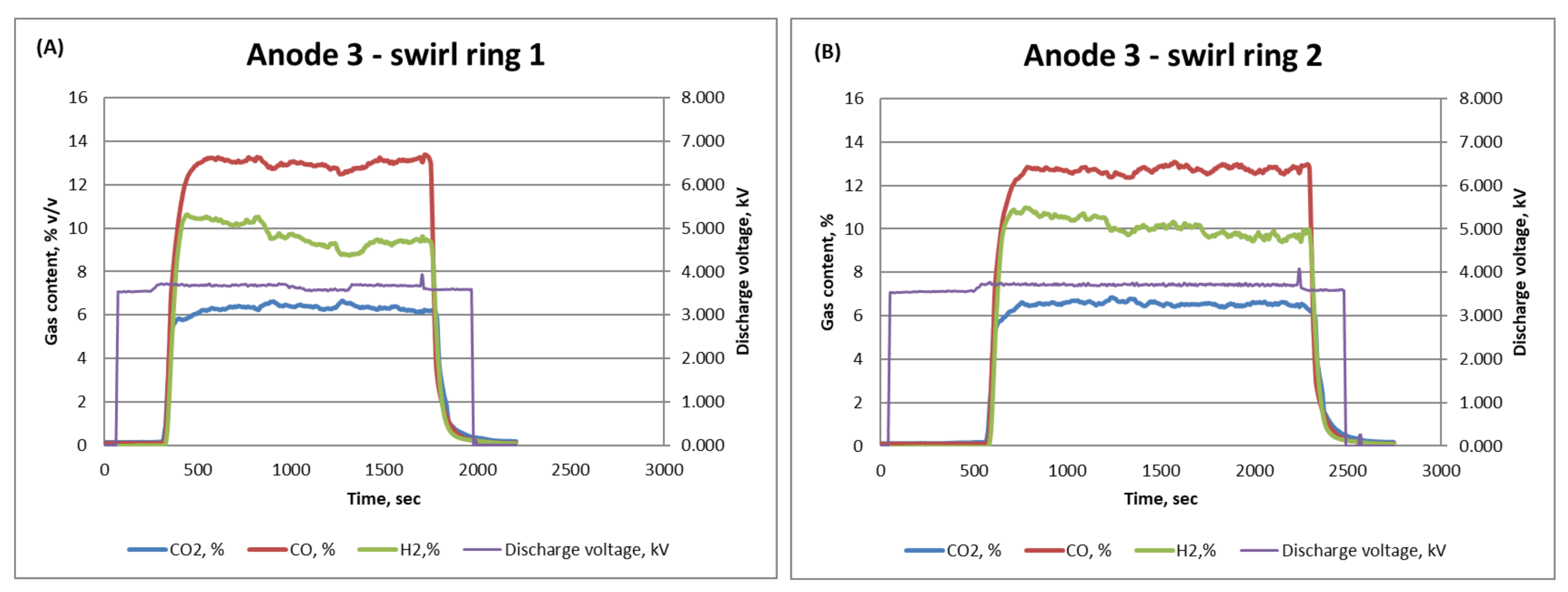
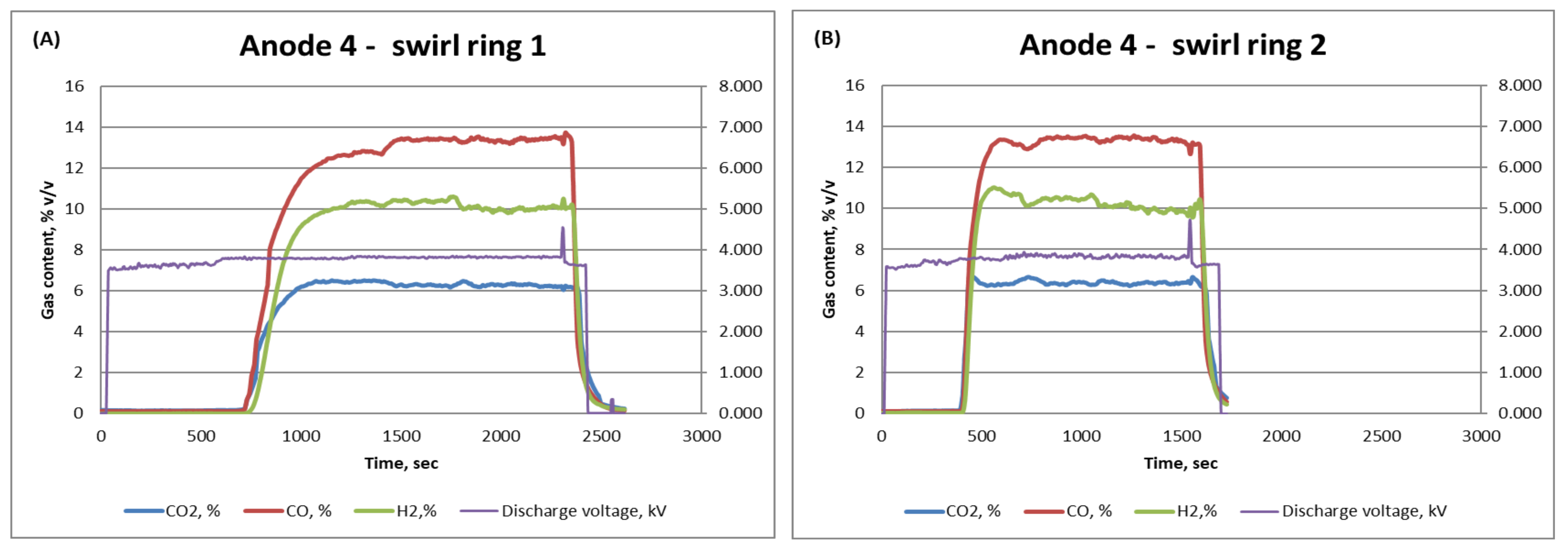
| Design | H2% | CO% | CO2% |
|---|---|---|---|
| Anode 1—Ring 1 | 24 | 19 | 9 |
| Anode 1—Ring 2 | 21 | 16 | 6 |
| Anode 2—Ring 1 | 12 | 14 | 7 |
| Anode 2—Ring 2 | 12 | 15 | 5.5 |
| Anode 3—Ring 1 | 15 | 13 | 7 |
| Anode 3—Ring 2 | 11 | 13 | 7 |
| Anode 4—Ring 1 | 10.5 | 14 | 6 |
| Anode 4—Ring 2 | 11 | 13 | 6 |
Publisher’s Note: MDPI stays neutral with regard to jurisdictional claims in published maps and institutional affiliations. |
© 2022 by the authors. Licensee MDPI, Basel, Switzerland. This article is an open access article distributed under the terms and conditions of the Creative Commons Attribution (CC BY) license (https://creativecommons.org/licenses/by/4.0/).
Share and Cite
Alharbi, A.A.; Alqahtani, N.B.; Alkhedhair, A.M.; Alabduly, A.J.; Almaleki, A.A.; Almadih, M.H.; Albishi, M.S.; Almayeef, A.A. A Developed Plasmatron Design to Enhance Production of Hydrogen in Synthesis Gas Produced by a Fuel Reformer System. Energies 2022, 15, 1071. https://doi.org/10.3390/en15031071
Alharbi AA, Alqahtani NB, Alkhedhair AM, Alabduly AJ, Almaleki AA, Almadih MH, Albishi MS, Almayeef AA. A Developed Plasmatron Design to Enhance Production of Hydrogen in Synthesis Gas Produced by a Fuel Reformer System. Energies. 2022; 15(3):1071. https://doi.org/10.3390/en15031071
Chicago/Turabian StyleAlharbi, Ahmed A., Naif B. Alqahtani, Abdullah M. Alkhedhair, Abdullah J. Alabduly, Ahmad A. Almaleki, Mustafa H. Almadih, Miqad S. Albishi, and Abdullah A. Almayeef. 2022. "A Developed Plasmatron Design to Enhance Production of Hydrogen in Synthesis Gas Produced by a Fuel Reformer System" Energies 15, no. 3: 1071. https://doi.org/10.3390/en15031071
APA StyleAlharbi, A. A., Alqahtani, N. B., Alkhedhair, A. M., Alabduly, A. J., Almaleki, A. A., Almadih, M. H., Albishi, M. S., & Almayeef, A. A. (2022). A Developed Plasmatron Design to Enhance Production of Hydrogen in Synthesis Gas Produced by a Fuel Reformer System. Energies, 15(3), 1071. https://doi.org/10.3390/en15031071