Article

Development of Thermal Barrier Coating Systems from Al Microparticles—Part II: Characterisation of Mechanical and Thermal Transport Properties

by
Germain Boissonnet
*,
Jean-Luc Grosseau-Poussard
,
Gilles Bonnet
and
Fernando Pedraza
Laboratoire des Sciences de l’Ingénieur Pour l’Environnement—Université de La Rochelle LaSIE, UMR-CNRS 7356, Avenue Michel Crépeau, CEDEX 1, 17042 La Rochelle, France
*
Author to whom correspondence should be addressed.
Coatings 2022, 12(2), 106; https://doi.org/10.3390/coatings12020106
Submission received: 30 December 2021 / Revised: 14 January 2022 / Accepted: 15 January 2022 / Published: 18 January 2022
(This article belongs to the Special Issue Coatings in 2022)

Abstract

:
In this study, the mechanical resistance and the thermal insulation potential of novel thermal barrier coatings (TBCs) made of a foam of hollow alumina particles are assessed through scratch testing, micro-indentation and thermal diffusivity measurements using laser-flash. The thermal diffusivity of the foam coatings ranges between 0.6 × 10⁻⁷ and 5 × 10⁻⁷ m2·s−1 and is thus comparable with the thermal insulation potential of the standard plasma-sprayed (PS) and electron beam–physical vapour-deposited (EB-PVD) TBCs made of yttria-stabilised zirconia (YSZ). The coatings annealed in more oxidative atmospheres exhibit greater mechanical resistance due to the thickening of the alumina shells and the increased sintering of the foam. However, when the oxidation is poorly tailored, the adhesion of the foam to the substrate decreases due to the presence of unwanted oxide that grows at the substrate/coating interface.

1. Introduction

The current demand for greater efficiency and a reduction in fuel consumption and greenhouse gas emissions requires higher-temperature operating conditions in gas turbines, including in the low-pressure turbine (LPT) section [1]. Finding alternative coating technologies to the standard thermal barrier coatings (TBCs) to extend the protection to the lower stages of the turbine is thus of growing interest as the current processes are expensive and complex. Among the different options, the formation of a complete thermal barrier coating using the slurry technique appears to be attractive for the materials of the LPT section due to its relatively low cost and ease of application [2]. This technology often uses an aqueous slurry that contains Al microparticles, which forms a foam of hollow alumina microspheres on top of an aluminide coating after proper annealing [3,4]. In a previous study, the resulting 40 μm thick foam coating was shown to confer equivalent insulative properties to those of a conventional 400 μm YSZ TBC deposited by plasma spray [5]. However, this thin foam did not display sufficient resistance to erosion by grit blasting because of the thin oxide shell of the alumina hollow spheres [6]. Previous studies that investigated the role of the microparticles’ properties [7], the mechanisms of coating formation [8] or the influence of the annealing gases [9,10] on the formation of such coatings showed that it was possible to obtain different foam top coatings by varying the parameters of the annealing conditions or the microparticles of the slurry itself. In an attempt to thicken the shell and enhance the sintering of the hollow spheres, hence to improve the mechanical strength of the insulative foam, previous research aimed at controlling the annealing atmosphere to promote the growth of the oxide shells of the original microparticles while enabling enough Al to react with the Ni substrate to form the diffusion coating [11]. It was demonstrated that annealing in air and in water vapour thickened the oxide shells but hampered the diffusion of Al into the Ni substrate. The opposite occurred in Ar, i.e., the aluminide coating was thick and even but the foam on top had very thin oxide shells. Annealing first in Ar and then switching to an oxidising gas (air or water vapour) resulted in a compromise between the thickening of the shells and the supply of Al to form the diffusion layer. The different annealing processes in single and hybrid atmospheres resulted in various microstructures of the coating systems with, for instance, different top foam and oxide shell thicknesses, homogeneity of the aluminide and the presence of oxide and un-emptied Al microparticles in the top coating.
However, the mechanical strength, adhesion and thermal insulation properties were not investigated in this previous study as it mostly focused on the coating formation mechanisms. Therefore, this work aims at filling this gap to determine the relevance and applicability of such new thermal barrier coatings by evaluating the mechanical resistance and adherence of the foam using micro-indentation and scratch tests. The thermal insulation potential will be assessed via the measurement of the thermal diffusivity of the top foam via laser-flash analyses.

2. Materials and Methods

2.1. Materials and Microstructural Characterisation

The coatings were performed on pure Ni (99.98% purity, Goodfellow, Lille, France) disc samples of 12.7 mm diameter. The coatings were achieved by the heat treatment of slurries made from Al micro-sized particles that were previously sprayed on the surfaces of the Ni substrates. Two different types of Al powder were used: the first with a homogeneous size distribution and that possessed a slightly thicker passive shell (HS), and the other of a more dispersed size distribution with thin passive shells (DS). After the deposition of the slurry (approximately 9 ± 1 mg∙cm−2), the samples were dried in a fume cupboard for 1 h and annealed in a thermobalance following a three-step heating program. With heating ramps fixed at 5 °C∙min−1, the samples were first cured at 400 °C to remove the organic binder (polyvinyl alcohol), then heated at 700 °C for 2 h to allow the Al to melt and to diffuse into the substrate and finally annealed at 1100 °C for 2 h to stabilise the oxide into α-Al2O3 and the diffusion coating into a β-NiAl phase. The thermal treatments were conducted into different atmospheres to optimise the thickening of the shells by oxidising the leaking Al coming out of the micro-sized particles while allowing enough Al to reach the substrate to form the underlying aluminide coating [4]. For this purpose, Ar and synthetic air were employed to perform the thermal treatments. Moreover, heat treatments were investigated in hybrid atmospheres, where the initial Ar was replaced with synthetic air at different temperatures of annealing during the heating ramp from 400 to 700 °C. Table 1 shows a summary of the samples with the different heat treatments performed.
The analyses of the surfaces and cross-sections of the samples were carried out using scanning electron microscopy (SEM FEI Quanta 200F, Eindhoven, The Netherlands) coupled to an energy dispersive X-ray spectroscopy detector (EDS EDAX, Leicester, UK) for elemental analysis. Each sample was mounted in an epoxy resin and cross-sections were mirror-polished using 1 µ diamond paste (Nap B1 STRUERS, Ballerup, Denmark).

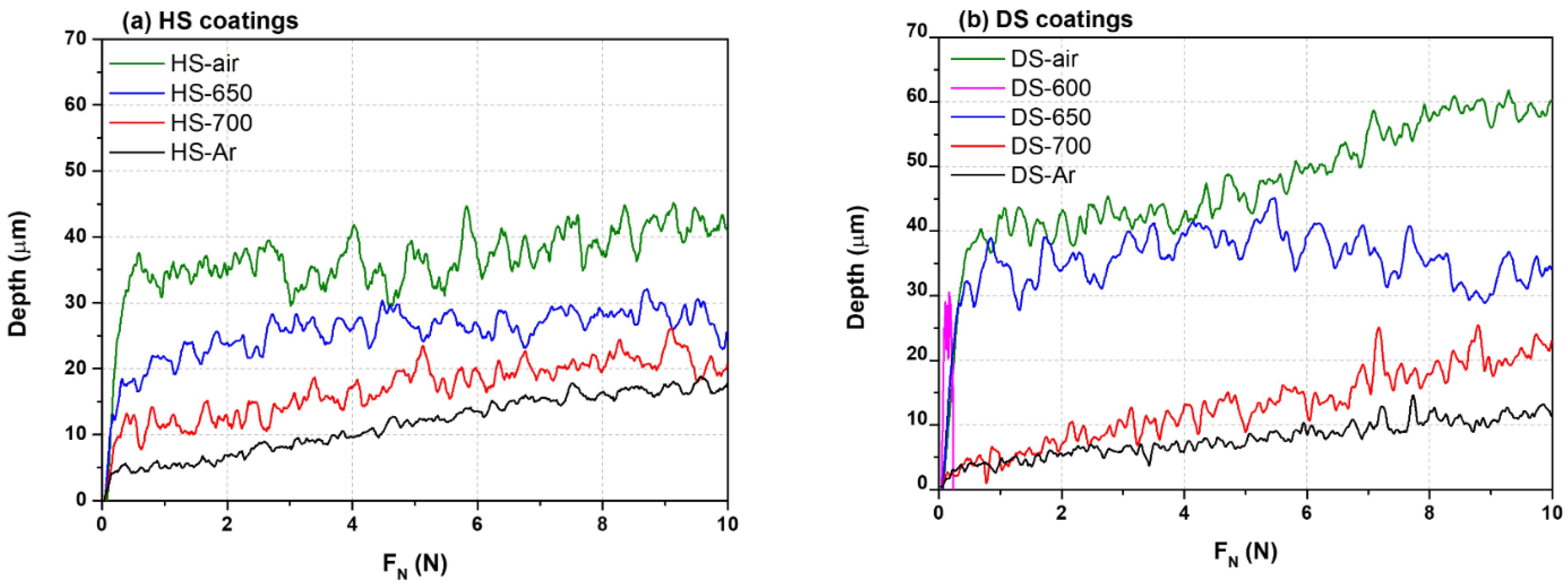
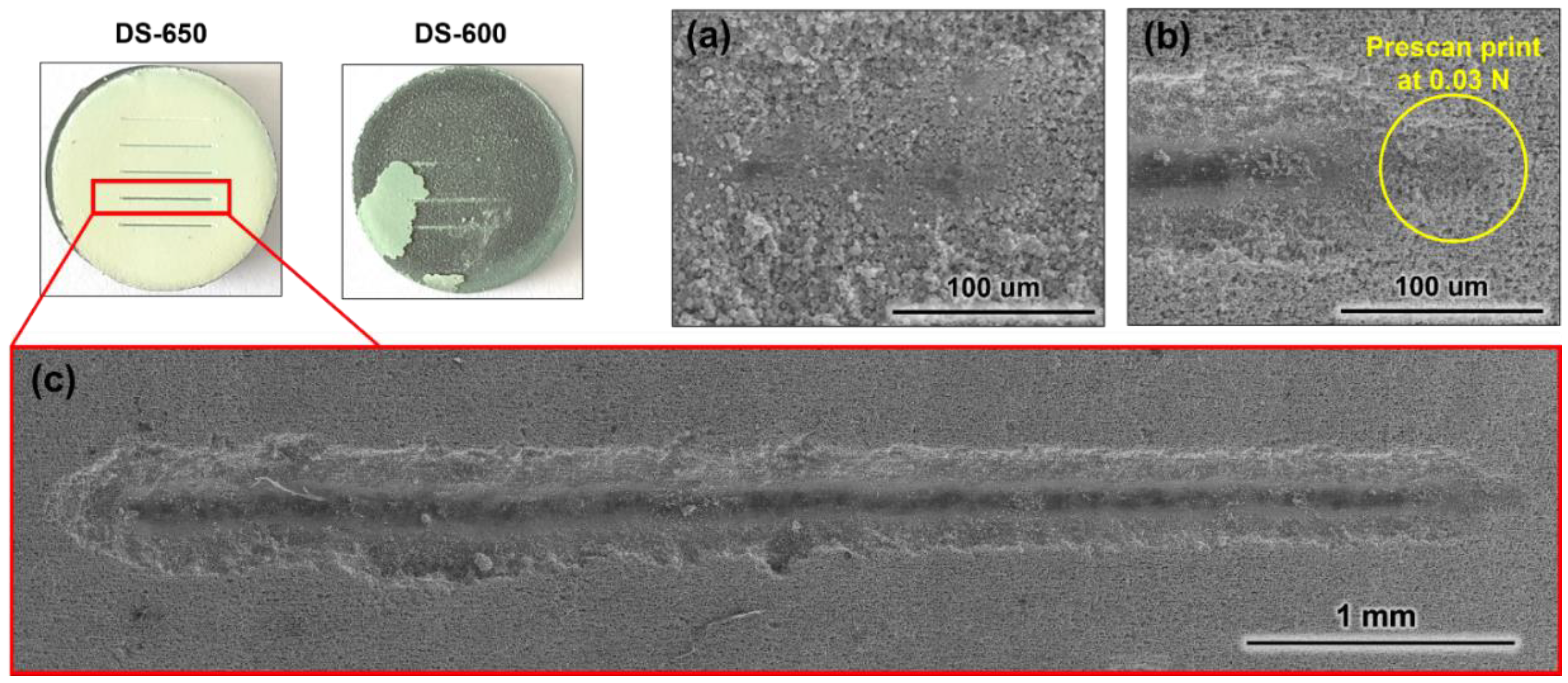
2.2. Scratch Tests and Micro-Indentation

Micro-indentation was performed to assess the mechanical resistance of the coatings studied and to compare them with the standard YSZ thermal barrier coatings made by plasma spray or EB-PVD that are presented in other studies [12,13]. To compare the different coatings, the normal force applied for the penetration of Vickers indents was recorded as a function of the depth of penetration till reaching 5 μm into the coating. This depth was chosen in accordance with the different coating thicknesses to allow the comparison of all the different coatings with one single criterion.
While micro-indentation is the most common method to measure the hardness of the coatings, the scratch test is a well-known technique that is used to assess the coating/substrate adhesion of a thin hard coating on different types of substrates [14]. This adhesion is measured from an indent that is drawn across the coated surface with an increasing load until a defined failure occurs at a load known as the critical load, LC. Depending on multiple factors that are usually reduced to the hardness of both substrate and coating, different modes of failure, which include coating detachment, through-thickness cracking, plastic deformation or cracking in the coating or substrate, may occur during the scratch test. Moreover, some authors claim that the scratch test can also be used to assess the resistance to abrasion of thick coatings [15,16]. Therefore, the adherence of the TBCs made from the slurry route was assessed using the scratch test method. Scratching experiments were performed using a scratch tester (ANTON-PARR STEP E400, Anton-Parr, Les Ulis, France) with a Rockwell-M-120 (Anton-Parr, Les Ulis, France) diamond indenter with a 100 μm tip radius coupled to an acoustic emission sensor. The range load was set from 0.03 to 10 N over a length of 5 mm, with a speed rate of 2.5 mm∙min−1 and an acquisition rate of 30 Hz.
It should be noted that a pre-scan at 0.03 N was performed prior to each scratch or micro-indentation test to identify the original surface of the sample and, thus, was already damageable to the weakest coatings as it could already penetrate them. Therefore, the measured depth must be considered carefully. Additional indentation at 0.03 N using the same indenter was performed on the different coatings to assess the impact of the pre-scan.

2.3. Thermal Insulation Assessment

The thermal conductivity (λ) is usually employed in the literature to describe the thermal insulation potential of thermal barrier coatings; it is derived from the thermal diffusivity (α), the density ( ρ ) and the specific heat capacity (Cp) following Equation (1):
λ ( T ) = α ( T ) × ρ ( T ) × C p ( T )
However, as the coatings present various porous microstructures, it is very complex to measure the specific heat capacity or the density of the coatings with the precision needed to calculate the true thermal conductivity at high temperatures. Therefore, as stated in other studies, it is often preferred to discuss the thermal diffusivity of the coatings in a comparative manner to assess the thermal insulation potential of such coatings [12,17]. The high-temperature thermal diffusivity was determined using a laser-flash apparatus (LFA 1600 LINSEIS, Selb, Germany) working under a vacuum (~1 × 10⁻² mbar), with the measurements being made every 100 °C from room temperature till 1100 °C. Prior to the laser-flash measurements, the thickness of the samples was determined using a digital calliper (±10−3) and both surfaces of the disc samples were coated with a 4–5 μm graphite layer to increase the absorption of the laser pulse on the back side, as well as the emissivity of the heat signal on the front side to be measured with the InSb infrared detector. For post-processing, multi-layer calculations (2-layer model) were employed to extract the contribution of the coating. The thickness of each layer was measured from the cross-section images.

3. Results

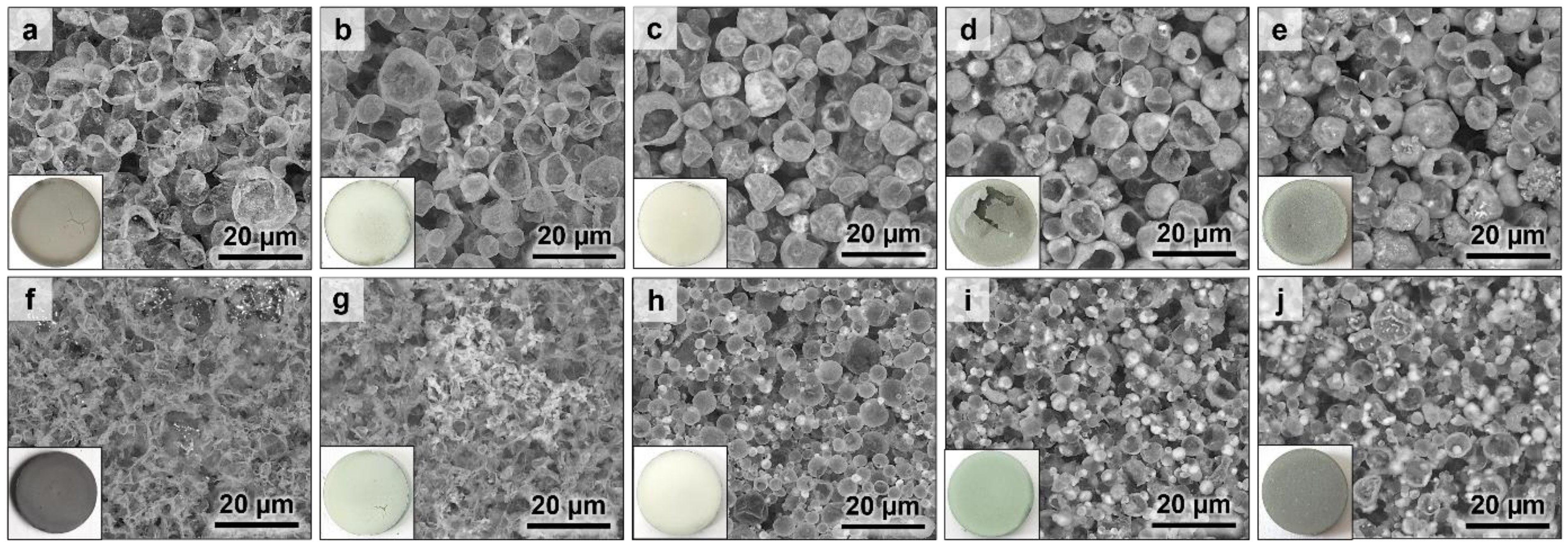
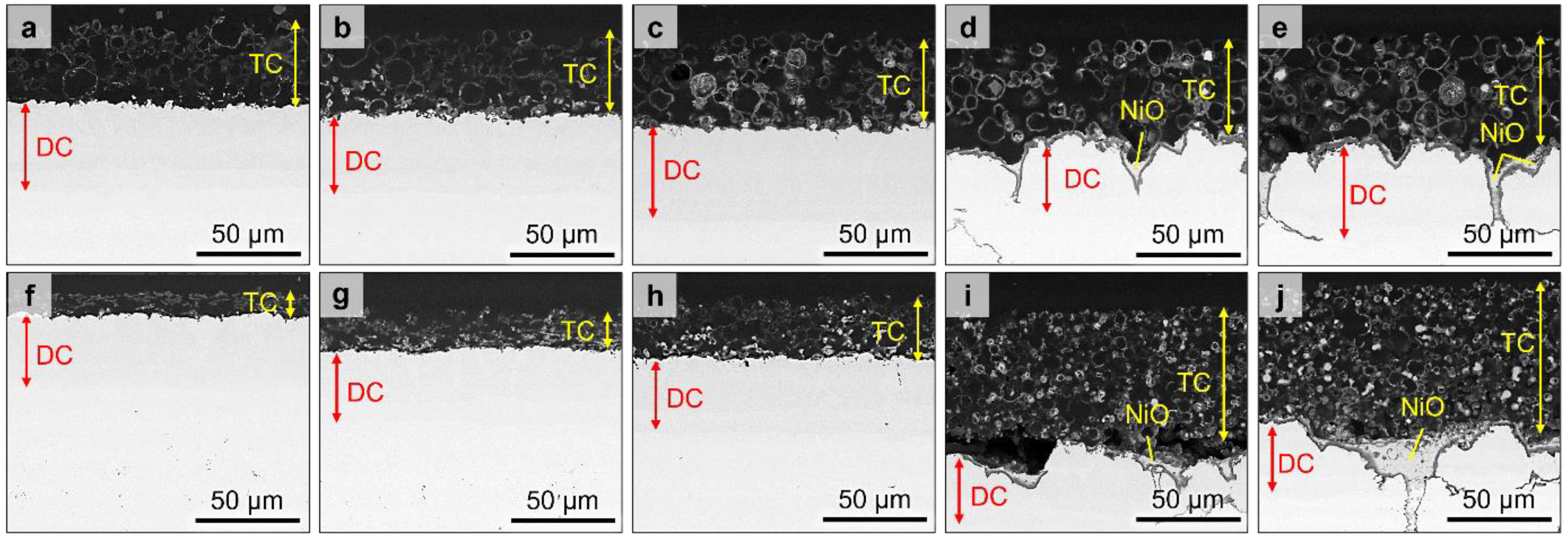
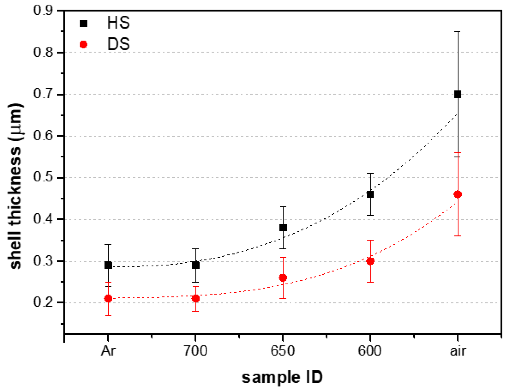
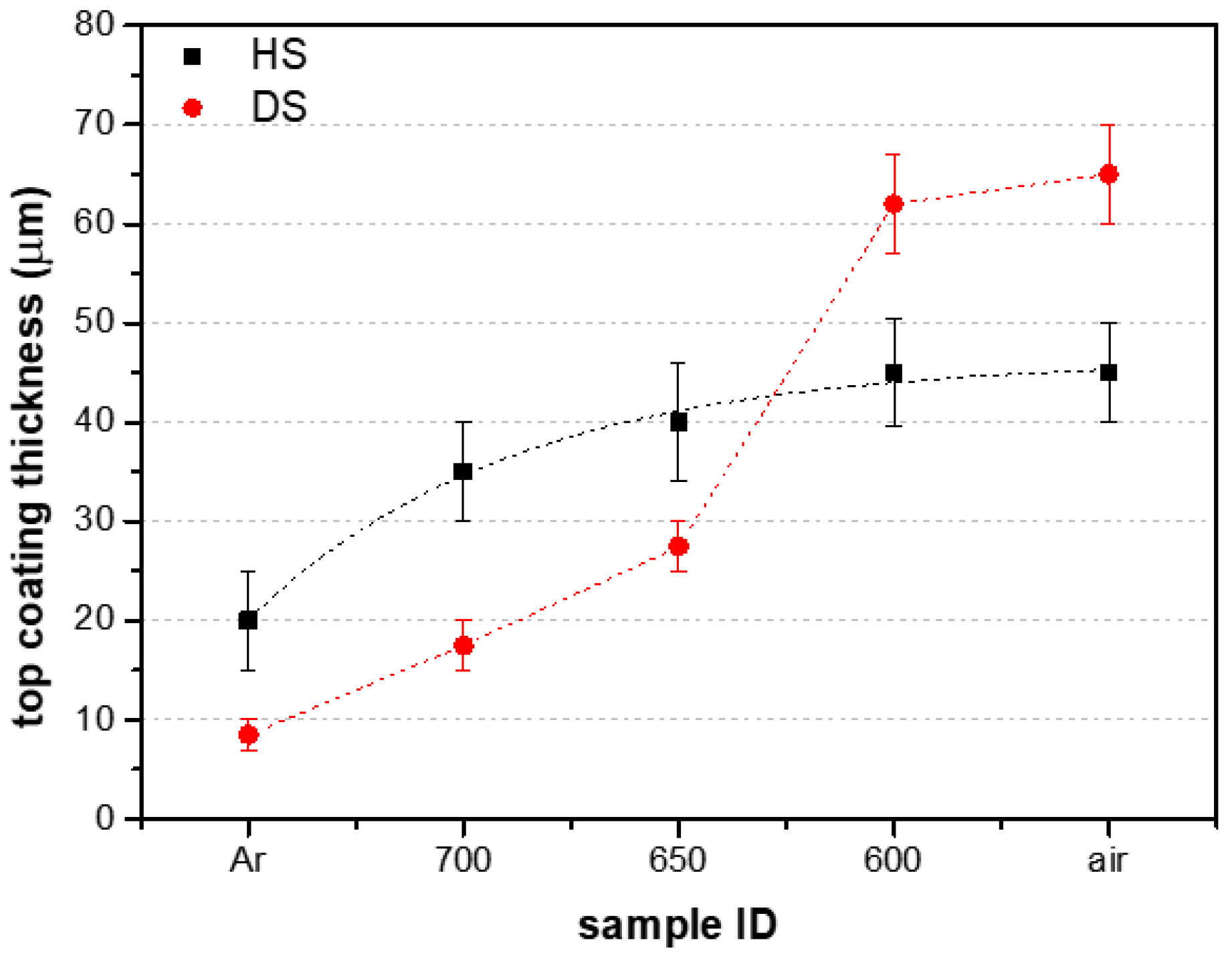
3.1. Microstructure of the Thermal Barrier Systems

Figure 1 and Figure 2 gather, respectively, the surfaces and the cross-sections of the coatings that were synthesised with the different annealing atmospheres. As expected, a wide variety of coating microstructures were obtained due to the differences in the type of Al microparticles and the duration of exposure to the oxidative atmosphere (full Ar < air introduced at 700 °C < 650 °C < 600 °C < 550 °C < full synthetic air).
In the Ar atmosphere, both the DS and HS microparticles resulted in thin top coatings made of the collapsed hollow particles, i.e., ~8 µm for DS-Ar (Figure 1a and Figure 2a) and ~20 µm for HS-Ar (Figure 1f and Figure 2f). The insets in Figure 1 correspond to the macroscopic images of the surface, which clearly show a dark grey aspect when the coatings had been annealed in Ar (Figure 1a,f) and fully in air (Figure 1e,j). The former is due to the poor oxidation of the top coatings, i.e., the hollow microparticles have such thin shells that it is possible to see the substrate colour through, while, in the latter, the grey aspect is associated with the trapped metallic Al. In full air, the resulting top coatings are thick due to the early oxidation of the particles, i.e., ~60 µm for DS-air and ~50 µm for HS-air, but the diffusion coatings obtained are heterogeneous and display a NiO layer on top of a thick alumina thermally grown layer. By modifying the temperature of the introduction of synthetic air as a replacement for the Ar atmosphere during the heat treatment, various microstructures are achieved. Introducing the synthetic air at 600 °C leads to the significant oxidation of the coatings. In contrast with the complete heat treatment in air, the switch from Ar to air at 600 °C leads to spallation of the top coating for the HS-600 sample (Figure 1d and Figure 2d) and to cracks and voids at the interface between the diffusion coating and the top coating for the DS-600 sample (Figure 2i). Delaying the introduction of air to higher temperatures results in homogeneous diffusion coatings with thicker top coatings than the ones obtained with pure Ar, i.e., ~40, ~35, ~30 and ~15 µm for HS-650, HS-700, DS-650 and DS-700, respectively (Figure 2b,c,g,h).
Figure 3 and Figure 4 display, respectively, the thickness of the shell of the emptied microparticles and the thickness of the top coating, thereby highlighting the increasing oxidation potential of the annealing atmospheres. For both types of microparticles, the thickness of the walls from the microspheres and the top coating thickness tend to increase with greater exposure to the oxidising atmosphere. Figure 3 shows that the oxide shell of the HS particles is greater than the DS ones for all the different heat treatments, yet their thickening rate with increasing oxidising potential is similar. However, the evolution of the top coating thickness displayed in Figure 4 is very different in the two types of particles. While the HS microparticles lead to the slow growth of the coating thickness, the DS microparticles show a marked increase in the growth of the top coating with the most oxidising conditions, i.e., with air introduced at 600 °C and in full air.

3.2. Mechanical Tests

Figure 5 shows the penetration depth of the indent in the coatings as a function of the applied force across the length of the scratch line. Table 2 gathers the penetration depth measured in different locations. Since the coating of the HS-600 sample had already spalled from the surface, no scratch was performed on its surface. Similarly, the coating of the DS-600 samples spalled during the scratch test and is observed on Figure 5b as a sharp drop in the penetration depth, which was registered in the early stage of the scratch (see also the macroscopic image of the DS-600 sample after the scratch test in Figure 6). All the other coatings remained adherent to the underlying coating after the scratch tests. The recorded depths against the applied load (Figure 5) followed a two-stage sequence: (1) Over the first microns of the scratch, the indent tends to penetrate the whole thickness of the coatings, as highlighted by the early increase in the measured depth. The maximum penetrated depth (Dmax in Table 2) appears to be similar. In the DS microparticles and for the leanest oxidising conditions, i.e., Ar, 700 and 650 °C, the penetration depth is even greater than the thickness of the top coatings (Table 2).
In contrast, the measured depth at 0.5 N (D0.5N in Table 2) corresponds to values close to the total coating thickness. However, it is important to consider the contribution of the pre-scan performed at 0.03 N since the penetration of the indent is already quite significant compared to the coating thickness (see Figure 6b and D0.03N in Table 2). Therefore, within uncertainty, the D0.03N values show that the penetration of the indent is already quite significant compared to the coating thickness, and, thus, this D0.03N value should be added to the Dmax and D0.5N depths to obtain the effective penetrated depth. It is also observed that the D0.03N tends to decrease as the top coatings are more oxidised (700 < 650 < air). In contrast, the coatings annealed in Ar exhibit the smallest penetration at 0.03 N in line with the thinnest coating thicknesses. In addition, for the most oxidised and thickest coatings, the measured depth follows a stable stage after the sharp increase until a given value of applied force is reached. (2) Afterwards, the penetration of the indent tends to reach a steady stage before increasing again as it starts to reach the diffusion coating. Figure 6 shows an example of a scratch that was observed by SEM. Except for the DS-600 sample, where the coating completely detached from the substrate, every scratch performed resembles the one presented for the DS-650 sample in Figure 6c. As the micrograph from Figure 6b shows, the indenter penetrates and reaches the substrate surface (the aluminide coating) at the early stage of the scratch, where the applied force is less than 0.5 N.
In addition, Figure 6c shows barely any spallation of the coating around the scratch. Except for the DS-600 sample, which lost its coating after the scratch, and the HS-600 sample, where the coating was already detached from the substrate, the absence of spallation in the different coatings suggests that the adhesion strength of the coating to the substrate is greater than the cohesive strength of the microspheres from the foam.
To further assess the difference in terms of mechanical strength, micro-indentation tests were performed on the different top coatings produced. The force needed to penetrate the first 5 µm of the different coatings is shown in Table 3. Except for the thin top coatings performed in the Ar atmosphere, where the underlying substrate is rapidly reached, the force required to penetrate the 5 µm increases with increasing oxidation of the microparticles from the top coating. The micro-indentations performed on the APS and EB-PVD YSZ coatings show that there is a significant difference between the mechanical strength of the standard TBCs and the Al slurry ones. As a matter of fact, the indentations in the plasma-sprayed coatings resulted in an average load that was 10 times higher (~200 mN) than the Al slurry coatings performed in synthetic air. The indentations performed on the EB-PVD coatings were even higher but showed a wide dispersion of the values due to the inherent heterogeneity of the surfaces of these columnar coatings.

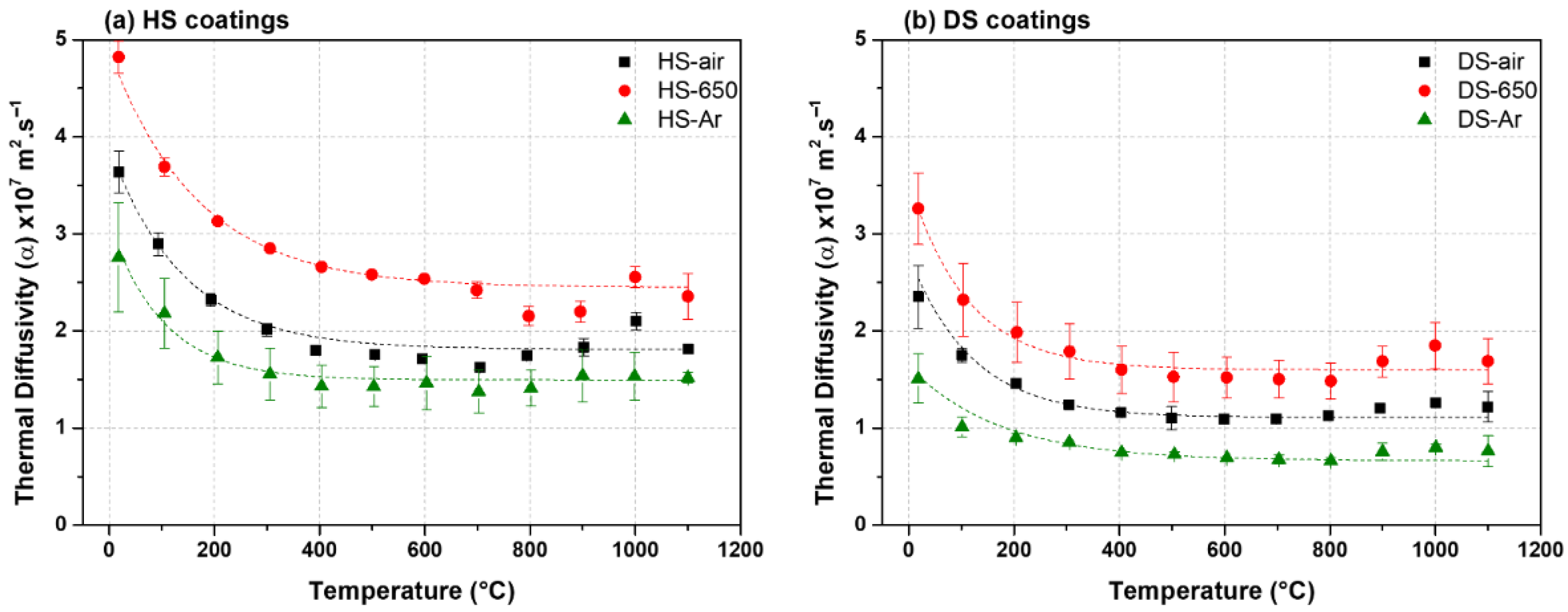
3.3. Thermal Diffusivity

The thermal diffusivity of the top coatings calculated via laser-flash measurements of the complete system (substrate + aluminide + top coating) is presented in Figure 7. All the coatings display thermal diffusivity values ranging between 0.8 × 10⁻⁷ and 5.0 × 10⁻⁷ m2·s−1 and a decreasing trend with increasing temperature. When comparing the two different types of microparticles, the HS microparticle-based coatings display higher thermal diffusivity than the DS ones, with ranges from 1.4 × 10⁻⁷ to 5.0 × 10⁻⁷ m2·s−1 and 0.8 × 10⁻⁷ to 3.3 × 10⁻⁷ m2·s−1, respectively. Irrespective of the type of microparticles (DS or HS), the lowest thermal diffusivity is found for the least oxidised coatings (Ar) and the highest for those sintered in Ar + air at 650 °C.

4. Discussion

The mechanisms of formation of the coatings characterised here were fully discussed in our previous work [11]. Therefore, the microstructural aspects of the coatings obtained in the different annealing conditions are only briefly recalled here.
Annealing in a quasi-inert Ar atmosphere leads to the fast consumption of the Al from the slurry HS and DS microparticles to form the aluminide coating and the subsequent collapse of the remaining emptied shells from the top coating. The collapse was reported to occur from the shrinkage of the thin alumina shells when γ-Al2O3 transforms into α-Al2O3 after exposure to temperatures above 1000 °C [7,11,18,19]. The greater collapse of the foam top coating for the DS-Ar than for the HS-Ar sample is probably due to the thinner passive shell of the DS microparticles (Figure 1a,f and Figure 2a,f). The oxide shell thickness measured after the heat treatments for the DS particles is very thin (~0.2 µm) (Figure 4). Therefore, when Al starts to melt (around 660 °C), the shells are not thick enough to avoid collapsing upon the γ to α-Al2O3 transition (see Figure 2f). The HS particles that display thicker shells, i.e., ~0.3 µm after the heat treatment in Ar, can withstand the transition and seem to keep a quasi-spherical shape (see the cross-sections in Figure 2a). In addition, the scratch tests performed on these thin coatings did not cause the detachment of the foam top coatings but resulted instead in the crushing of the hollow microspheres. Since top coatings result from the sintering of the small hollow oxide spheres on top of a hard aluminide coating, plastic deformation is supposed to be minimal, and fracture should dominate the scratch response [14]. Therefore, as the strength of the oxide shells built under the Ar atmosphere was very poor, the scratch only showed the brittleness and the poor cohesive strength of the foam coating. The micro-indentation tests performed on the DS-Ar and HS-Ar even showed higher values of the load needed to penetrate 5 microns (see Table 3) than that of the coatings annealed in the other conditions. As the indenter rapidly reached the aluminide surface, it was not possible to properly measure the contribution of the top foam coating itself. Such poor mechanical strength was also observed in previous works and is at the origin of the study that sought to improve the strength of the top foam [11].
Annealing in synthetic air to improve the mechanical strength of the top foam coating resulted in the oxidation of the substrate, which hampered the diffusion of the aluminium from the microparticles to form the aluminide coating (Figure 2e,j). However, such oxidation also resulted in an increase in the shell thickness of the microparticles (~0.5 and ~0.7 µm for DS and HS particles, respectively) and a reduction in the collapsing of the emptied microspheres that led to thicker top foam coatings for the heat treatment in air compared to Ar (see Figure 3 and Figure 4). The scratch tests showed good adhesion of the foam coating to the substrate, despite the stiffness of the foam increasing with the thickening of the shell and the sintering caused by the oxidation of the aluminium of the microparticles. This increase in hardness was highlighted by micro-indentation (see Table 3) and both the HS-air and DS-air showed higher resistance to indentation than the coatings with the introduction of the synthetic air during the heat treatment.
By introducing the synthetic air at different temperatures upon annealing, different improvements are achieved in comparison with the treatment performed under Ar or synthetic air only. Delaying the introduction of air from 700 to 650 °C and then to 600 °C increases the exposure time to oxidising conditions, which in turn results in thicker oxide shells and thicker top coatings than with a heat treatment under Ar only (see Figure 3 and Figure 4). With the introduction of air at 700 °C, almost no improvement was achieved in the thickness of the microsphere shells in comparison with the full Ar heat treatment, but the introduction of air allowed a slight reduction in the collapse of the microspheres as the top coating achieved was thicker than that under the Ar atmosphere. When air was introduced at 600 °C, the thickness of the shells and of the top coatings for both types of particles was greatly improved. However, as with the heat treatment performed under air, the oxidation of the substrate hampers the formation of a homogeneous aluminide coating. In turn, the introduction of air at 650 °C results in a good compromise between the formation of an aluminide coating and of the topcoat foam with thick shells.
The thickening of the oxide shells (Figure 3) leads to greater resistance to the penetration of the indent (5 μm into the coating) when the oxidation time increases, e.g., from 8.5–9.6 to 12–12.6 N with air introduced at, respectively, 700 and 650 °C (Table 3). However, when compared with the bulk APS and EB-PVD YSZ coatings, the porous foam coating achieved in this study is still 20 to 75 times less resistant. Nevertheless, the porosity of the foam coatings cannot be compared with that of the bulk coatings, which can reach, for instance, a maximum of ~25% porosity for the standard plasma-sprayed YSZ coatings [12].
The high porosity of the foam coatings achieved in this study thus led to great thermal insulation properties. The coatings produced in Ar present the lowest thermal diffusivities since the shell of the microparticles that trap air is very thin. As a matter of fact, heat conduction is greater in alumina (λalumina ~ 5–35 W·m−1·K−1 at RT) than in the gas filled pores (λair ~ 0.025 W·m−1·K−1 at RT) and could decrease even further when the pores are smaller than the gas mean free path (typically pores ~1 μm), where the heat conduction of the gas falls below the conduction of the free gas to ~0.01 W·m−1·K−1 due to gas molecule–wall collisions (Knudsen conduction) [6,7,8]. However, the top coatings that were heat-treated in air present lower thermal diffusivities than the ones heat-treated in Ar + air introduced at 650 °C, despite the thicker shells of the former. This can be attributed to the thick thermal oxide grown at the interface between the top coating and the diffusion coating for the samples heat-treated in synthetic air, which has been previously reported to add a non-negligible resistance to heat transport [12,13]. Moreover, the HS coatings exhibit higher thermal diffusivity values than the DS ones. This can be related to several factors that derive from the initial differences in particle size. Indeed, for the same coating thickness, the number of interfaces increases with decreasing the size of the particles. Therefore, and because interfaces are known to scatter heat in ceramic coatings [9,10,11], the greater the number of interfaces, the lower the thermal diffusivity. In addition, the HS microparticles whose shells are thicker than those of the DS ones will lead to higher heat conduction because the ratio of material vs. void is more significant. As also shown in previous studies, the thermal insulation potential of the foam coating is significant when compared with the standard APS and EB-PVD coatings, which reaches thermal diffusivities between 1 × 10⁻⁷ and 3 × 10⁻⁷ m2·s−1 for APS YSZ and between 3 × 10⁻⁷ and 6 × 10⁻⁷ m2·s−1 for EB-PVD YSZ coatings, while the range of thermal diffusivity for the slurry coatings in this study is from 0.6 × 10⁻⁷ to 5 × 10⁻⁷ m2·s−1 [12,13].

5. Conclusions

In this study, the mechanical resistance and the thermal insulation potential of novel thermal barrier coatings made of a foam of hollow alumina particles were assessed through scratch testing, micro-indentation and thermal diffusivity measurements.
  • All the coatings showed great thermal insulation properties on a par with the ones of the state-of-the-art YSZ TBCs made by plasma spraying or EB-PVD. Considering the foam coating and disregarding the potential thermal insulation of an interfacial thermally grown oxide, better thermal insulation is achieved with thinner shells.
  • The greater mechanical resistance of the foam coating is obtained with thicker shells of the hollow alumina spheres. This is achieved by increasing the exposure to air during the annealing step.
  • The scratch tests also allowed the comparison of the cohesion of the different coatings and only the DS-600 and HS-600 coatings spalled. All the other coatings possess good adhesive properties in comparison with the strength of cohesion of the alumina foam itself.

Author Contributions

Conceptualisation, G.B. (Germain Boissonnet) and F.P.; methodology, G.B. (Germain Boissonnet); software, G.B. (Germain Boissonnet); validation, G.B. (Gilles Bonnet), F.P. and J.-L.G.-P.; formal analysis, G.B. (Germain Boissonnet); investigation, G.B. (Germain Boissonnet); resources, F.P. and J.-L.G.-P.; writing—original draft preparation, G.B. (Germain Boissonnet); writing—review and editing, G.B. (Germain Boissonnet), F.P., G.B. (Gilles Bonnet) and J.-L.G.-P.; visualisation, G.B. (Germain Boissonnet); supervision, F.P. and G.B. (Gilles Bonnet); project administration, F.P.; funding acquisition, F.P. and G.B. (Gilles Bonnet). All authors have read and agreed to the published version of the manuscript.

Funding

This research was partially funded by the Région Poitou-Charentes.

Institutional Review Board Statement

Not applicable.

Informed Consent Statement

Not applicable.

Data Availability Statement

Data sharing is not applicable to this article.

Acknowledgments

The authors gratefully acknowledge the Région Poitou-Charentes for partially funding this research. The authors would also like to thank Claire Boulesteix for helping with the scratch tests and assessment of the results.

Conflicts of Interest

The authors declare no conflict of interest. The funders had no role in the design of the study; in the collection, analyses, or interpretation of data; in the writing of the manuscript, or in the decision to publish the results.

References

  1. Padture, N.P. Advanced Structural Ceramics in Aerospace Propulsion. Nat. Mater. 2016, 15, 804–809. [Google Scholar] [CrossRef] [PubMed]
  2. Mollard, M.; Rannou, B.; Bouchaud, B.; Balmain, J.; Bonnet, G.; Pedraza, F. Comparative Degradation of Nickel Aluminized by Slurry and by Pack Cementation under Isothermal Conditions. Corros. Sci. 2013, 66, 118–124. [Google Scholar] [CrossRef]
  3. Montero, X.; Galetz, M.; Schütze, M. A Single Step Process to Form In-Situ an Alumina Foam/Aluminide TBC System for Alloys in Extreme Environments at High Temperatures. Surf. Coat. Technol. 2011, 206, 1586–1594. [Google Scholar] [CrossRef]
  4. Pedraza, F.; Mollard, M.; Rannou, B.; Balmain, J.; Bouchaud, B.; Bonnet, G. Potential Thermal Barrier Coating Systems from Al Microparticles. Mechanisms of Coating Formation on Pure Nickel. Mater. Chem. Phys. 2012, 134, 700–705. [Google Scholar] [CrossRef]
  5. Pedraza, F.; Rannou, B.; Boissonnet, G.; Bouchaud, B.; Maache-Rezzoug, Z. Rheological Behaviour, Synthesis and Performance of Smart Thermal Barrier Coating Systems Based on Hollow Alumina. J. Mater. Sci. Chem. Eng. 2015, 3, 17–22. [Google Scholar] [CrossRef] [Green Version]
  6. Pedraza, F.; Boissonnet, G.; Fernandez, B.; Bouchaud, B.; Podor, R. Synthesis and Related Properties of Low k TBCs with Hollow Alumina Microspheres. Presented at the International Conference on Metallurgical Coatings and Thin Films (ICMTF), San Diego, CA, USA, April 2016. [Google Scholar]
  7. Kolarik, V.; Roussel, R.; Juez Lorenzo, M.; Fietzek, H. Factors Influencing the Formation of a Diffusion Zone and the Adherence of the Top Coat of High Temperature Coatings from Micro-Sized Spherical Aluminium Particles. Mater. High Temp. 2012, 29, 89–94. [Google Scholar] [CrossRef]
  8. Galetz, M.C.; Montero, X.; Mollard, M.; Günthner, M.; Pedraza, F.; Schütze, M. The Role of Combustion Synthesis in the Formation of Slurry Aluminization. Intermetallics 2014, 44, 8–17. [Google Scholar] [CrossRef]
  9. Brossard, M.; Bouchaud, B.; Pedraza, F. Influence of Water Vapour on the Oxidation Behaviour of a Conventional Aluminide and a New Thermal Barrier Coating System Sintered from a Slurry: Water Vapour Oxidation of Aluminide Coatings. Mater. Corros. 2014, 65, 161–168. [Google Scholar] [CrossRef]
  10. Pedraza, F.; Podor, R. Influence of Annealing Conditions on the Formation of Hollow Al2O3 Microspheres Studied by in Situ ESEM. Mater. Charact. 2016, 113, 198–206. [Google Scholar] [CrossRef] [Green Version]
  11. Boissonnet, G.; Grégoire, B.; Bonnet, G.; Pedraza, F. Development of Thermal Barrier Coating Systems from Al Microparticles. Part I: Influence of Processing Conditions on the Mechanisms of Formation. Surf. Coat. Technol. 2019, 380, 125085. [Google Scholar] [CrossRef]
  12. Boissonnet, G.; Bonnet, G.; Pasquet, A.; Bourhila, N.; Pedraza, F. Evolution of Thermal Insulation of Plasma-Sprayed Thermal Barrier Coating Systems with Exposure to High Temperature. J. Eur. Ceram. Soc. 2019, 39, 2111–2121. [Google Scholar] [CrossRef]
  13. Boissonnet, G.; Chalk, C.; Nicholls, J.R.; Bonnet, G.; Pedraza, F. Phase Stability and Thermal Insulation of YSZ and Erbia-Yttria Co-Doped Zirconia EB-PVD Thermal Barrier Coating Systems. Surf. Coat. Technol. 2020, 389, 125566. [Google Scholar] [CrossRef]
  14. Bull, S.J.; Berasetegui, E.G. An Overview of the Potential of Quantitative Coating Adhesion Measurement by Scratch Testing. Tribol. Int. 2006, 39, 99–114. [Google Scholar] [CrossRef]
  15. Li, Z.; Farhat, Z. The Effect of the Formation of Superelastic NiTi Phase on Static and Dynamic Corrosion Performance of Ni-P Coating. Solids 2021, 2, 278–292. [Google Scholar] [CrossRef]
  16. Vitry, V.; Sens, A.; Delaunois, F. Comparison of Various Electroless Nickel Coatings on Steel: Structure, Hardness and Abrasion Resistance. Mater. Sci. Forum 2014, 783–786, 1405–1413. [Google Scholar] [CrossRef]
  17. Taylor, R.E.; Wang, X.; Xu, X. Thermophysical Properties of Thermal Barrier Coatings. Surf. Coat. Technol. 1999, 120–121, 89–95. [Google Scholar] [CrossRef]
  18. Hasani, S.; Panjepour, M.; Shamanian, M. The Oxidation Mechanism of Pure Aluminum Powder Particles. Oxid. Met. 2012, 78, 179–195. [Google Scholar] [CrossRef]
  19. Hasani, S.; Soleymani, A.P.; Panjepour, M.; Ghaei, A. A Tension Analysis During Oxidation of Pure Aluminum Powder Particles: Non-Isothermal Condition. Oxid. Met. 2014, 82, 209–224. [Google Scholar] [CrossRef]
Figure 1. SEM surfaces of the coatings issued from (a) HS-Ar, (b) HS-700, (c) HS-650, (d) HS-600, (e) HS-air, (f) DS-Ar, (g) DS-700, (h) DS-650, (i) DS-600 and (j) DS-air.
Coatings 12 00106 g001
Figure 2. SEM cross-sections of the coatings issued from (a) HS-Ar, (b) HS-700, (c) HS-650, (d) HS-600, (e) HS-air, (f) DS-Ar, (g) DS-700, (h) DS-650, (i) DS-600 and (j) DS-air.
Coatings 12 00106 g002
Figure 3. Evolution of the shell thickness of the foam coatings with annealing atmosphere.
Coatings 12 00106 g003
Figure 4. Evolution of the thickness of the top coating with the annealing atmosphere.
Coatings 12 00106 g004
Figure 5. Penetration depth in the coatings as a function of the applied load FN during scratch tests. (a) HS coatings, (b) DS coatings.
Coatings 12 00106 g005
Figure 6. Macrographs of DS-650 and DS-600 after the scratch tests and corresponding SEM micrographs in SE mode of (a) the bottom of the scratch, (b) the beginning of the scratch and (c) the scratch in full length.
Coatings 12 00106 g006
Figure 7. Thermal diffusivity as a function of the temperature for (a) the HS foam coatings and (b) the HS foam coatings.
Coatings 12 00106 g007
Table 1. Summary of the different heat treatments performed in TGA. * The type of Al particle is defined with DS and HS, which correspond to “dispersed size” and “homogeneous size”, respectively.
Starting AtmosphereIntroduction of Synthetic AirSample ID *
Synthetic air-DS-air/HS-air
Ar550 °CDS-550/HS-550
Ar600 °CDS-600/HS-600
Ar650 °CDS-650/HS-650
Ar700 °CDS-700/HS-700
Ar-DS-Ar/HS-Ar
Table 2. Coating thickness and depth of penetration measured after the scratch tests. Dmax and D0.5N correspond to the maximum depth and the depth reached at 0.5 N of applied force, respectively. D0.03N* was assessed by additional indentations at 0.03 N.
Atmosphere of Heat TreatmentCoating Thickness (µm)Dmax (µm)D0.5N (µm)D0.03N* (µm)
HSDSHSDSHSDSHSDS
Ar20.0 ± 5.08.5 ± 1.519.014.74.53.95.9 ± 1.46.5 ± 2.4
Switch 700 °C35.0 ± 5.017.5 ± 2.523.425.710.24.811.0 ± 5.08.1 ± 1.1
Switch 650 °C40.0 ± 6.027.5 ± 2.532.245.218.632.49.3 ± 6.34.8 ± 0.9
Switch 600 °C45.0 ± 5.562.0 ± 5.0-30.6----
Synthetic air45.0 ± 5.065.0 ± 5.044.561.936.840.35.5 ± 2.25.9 ± 3.4
Table 3. Results of the micro-indentation tests with the average load (FN,av) applied to penetrate 5 microns into the different coatings.
Atmosphere of Heat TreatmentFN,av (mN)
HSDS
Ar19.6 ± 5.121.3 ± 9.3
Switch 700 °C8.5 ± 0.79.6 ± 2.3
Switch 650 °C12.0 ± 1.712.6 ± 4.5
Synthetic air17.6 ± 7.427.3 ± 4.5
Other Standard Thermal Barrier Coatings
APS YSZ201.3 ± 22.0 -
EB-PVD YSZ897.3 ± 229.0 -
Publisher’s Note: MDPI stays neutral with regard to jurisdictional claims in published maps and institutional affiliations.

