Article

Manufacture of a Polyaniline Nanofiber Ammonia Sensor Integrated with a Readout Circuit Using the CMOS-MEMS Technique

1
Department of Mechanical Engineering, National Chung Hsing University, Taichung, 402 Taiwan, ROC
2
Department of Mechanical and Electro-Mechanical Engineering, Tamkang University, Tamsui, 251 Taiwan, ROC
*
Author to whom correspondence should be addressed.
Sensors 2009, 9(2), 869-880; https://doi.org/10.3390/s90200869
Submission received: 13 December 2008 / Revised: 15 January 2009 / Accepted: 9 February 2009 / Published: 10 February 2009
(This article belongs to the Special Issue Gas Sensors 2009)

Abstract

:
This study presents the fabrication of a polyaniline nanofiber ammonia sensor integrated with a readout circuit on a chip using the commercial 0.35 μm complementary metal oxide semiconductor (CMOS) process and a post-process. The micro ammonia sensor consists of a sensing resistor and an ammonia sensing film. Polyaniline prepared by a chemical polymerization method was adopted as the ammonia sensing film. The fabrication of the ammonia sensor needs a post-process to etch the sacrificial layers and to expose the sensing resistor, and then the ammonia sensing film is coated on the sensing resistor. The ammonia sensor, which is of resistive type, changes its resistance when the sensing film adsorbs or desorbs ammonia gas. A readout circuit is employed to convert the resistance of the ammonia sensor into the voltage output. Experimental results show that the sensitivity of the ammonia sensor is about 0.88 mV/ppm at room temperature.

1. Introduction

Ammonia (NH3) is emitted by human activity. For instance, production of refrigeration systems and fertilizers emits ammonia. The worldwide ammonia emission resulting from domestic animals and industrial combustion is about 20-35 Tg/year and 2.1-8.1 Tg/year, respectively [1]. Ammonia is a toxic gas with exposure limit values of 25 ppm for a period of 8 h and of 35 ppm for a period of 10 min [2]. Ammonia sensors are important devices in many industrial, agricultural and biomedical applications. For instance, Boeker et al. [3] proposed an ammonia sensor based on a quartz crystal microbalance transducer for monitoring the ammonia concentration in agricultural emissions. Moos et al. [4] developed an ammonia gas sensor with a selective thick film of zeolites for automotive exhaust gas applications. Pushkarsky et al. [5] presented a laser-based photoacoustic ammonia sensor for industrial ammonia gas measurement.
Huang et al. [6] developed polyaniline nanofibers using interfacial polymerization at an aqueous and organic interface, and the resulting polyaniline, which had high surface area and porosity, could enhance properties in applications such as chemical sensors. With the same synthetic method, Virji et al. [7] fabricated polyaniline nanofiber gas sensors with performances that were better than conventional polyaniline. Thereby, the ammonia sensor in this work adopts polyaniline as a sensitive material. Microelectromechanical systems (MEMS) technology was applied to fabricate various microsensors. The advantages of microsensors include small size, high performance, low cost and easy mass-production. Many studies have recently utilized MEMS technology to manufacture ammonia sensors. For instance, Lee et al. [8] fabricated a micro ammonia gas sensor using a bulk micromachining technique. The sensor that was resistive type composed of a polyaniline film, a SU-8 adhesion layer and an interdigital Pt electrode, where the polyaniline film was the ammonia sensing film. The ammonia sensor had a sensitivity of about 40% at 50 ppm ammonia. Mitzner et al. [9] utilized a post-CMOS process to manufacture a micro-hotplate-based gas sensor array. The post-CMOS process adopted XeF2 to etch a silicon substrate to obtain the micro-hotplate array, and a SnO2/Pt sensing film was sputtered on this micro-hotplate forming a resistive-type ammonia sensor. Llobet et al. [10] utilized silicon process technology to make an ammonia sensor, in which the sensor consisted of a heater, an interdigital electrode, a temperature meter and a sensing film. Tungsten oxide, coated on the interdigital electrode, was adopted as an ammonia sensing film. Li et al. [11] presented a micro gas with piezoresistive SiO2 cantilever beam fabricated by a surface and bulk micromachining process. An ammonia sensing layer of 11-mercaaptoundecanoic acid was coated on the piezoresistive cantilever beams. The sensor was packaged with a linear amplifier, and its output voltage was about 7 μV in 1 ppm ammonia gas. Connolly et al. [12] reported a porous SiC ammonia sensor produced by silicon process technology, in which the sensor was a capacitive type. The sensing film of SiC was deposited by plasma enhanced chemical vapor deposition (PECVD) and was then made porous by electrochemical etching in 73% HF.
The use of a commercial CMOS process to fabricate MEMS devices is known as the CMOS-MEMS technique [13]. Several microdevices manufactured by the CMOS-MEMS technique need a post-process to coat the functional films or release the suspended structures. For instance, the suspended structures of the CMOS-MEMS switches [14] and pressure sensors [15] were released by a wet etching post-process. The main advantage of microdevices fabricated by the CMOS-MEMS technique is their ability to integrate with circuits as a system on a chip (SOC) because of their compatibility with the CMOS process. The ammonia sensors, proposed by Lee et al. [8], Mitzner et al. [9], Llobet et al. [10], Li et al. [11] and Connolly et al. [12], had no integration with circuitry on a chip. In this work, we employ the CMOS-MEMS technique to fabricate a polyaniline nanofiber ammonia sensor integrated with a readout circuit on a chip, which can reduce the volume and cost and enhance the performance. The area of the integrated ammonia sensor chip is about 0.6 mm2.

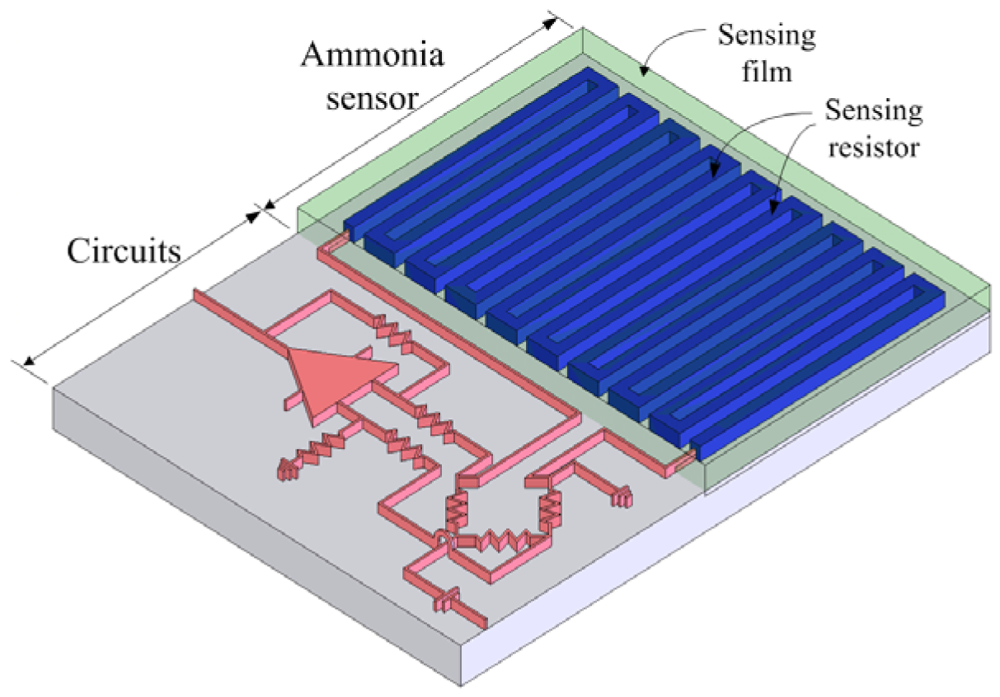
2. Structure of the Integrated Ammonia Sensor

Figure 1 shows the structure of the integrated chip, which contains an ammonia sensor and readout circuit. The ammonia sensor is composed of a sensing resistor and an ammonia sensing film. The sensing resistor is a polysilicon winding line. The ammonia sensing film, which is polyaniline prepared by a chemical polymerization method, is coated on the sensing resistor. A silicon dioxide layer is located between the sensing resistor and the polyaniline film. The sensing resistor is 2 μm wide, 0.4 μm thick and 9,000 μm long.
Figure 2 illustrates the energy band diagram of the ammonia sensor. When the polyaniline surface contacts air, holes are produced on this surface. As shown in Figure 2(a), an accumulation of holes is formed on the surface of the polyaniline film, so that the valence band edge of polyaniline bends upward and is close to the Fermi level of polyaniline. An accumulation of electrons at the oxide-polysilicon interface is formed [16], which causes the conduction band edge of polysilicon to bend downward and be close to the Fermi level of polysilicon. When polyaniline interacts with ammonia, the following reaction occurs [17]:
PANIH + + NH 3 PANI + NH 4 +
According to Equation (1), the H+ holes of polyaniline reduce as polyaniline interacts with NH3. As shown in 2(b), the accumulation of holes at the surface of polyaniline is reduced when polyaniline is exposed to ammonia, resulting in the valence band edge of reduced polyaniline bending and having a distance with the Fermi level of polyaniline, so that the resistance of polyaniline increases. At the same time, the accumulation of electrons at the oxide-polysilicon interface is reduced, which leads to the conduction band edge of polysilicon to reduce bending and have a distance with the Fermi level of polysilicon, so that the resistance of polysilicon increases.
Figure 3 presents the readout circuit for the ammonia sensor. The readout circuit consists of a Wheatstone circuit, an operational amplifier and resistances. As shown in Figure 3, the Wheatstone circuit is constituted by the sensing resistor (Rs) and three resistances (R1, R2 and R3). The sensing resistor changes its resistance as the sensing film adsorbs or desorbs ammonia gas. The readout circuit is utilized to convert the resistance of the ammonia sensor into the voltage output. In this design, R1=10 kΩ, R2=10 kΩ, R3=10 kΩ, R4=100 Ω, R5=10 kΩ, R6=10 kΩ and R7=10 kΩ are adopted. Figure 4 illustrates the operational amplifier circuitry for the readout circuit, where Vdd represents a voltage power supply and Vss is the ground.
HSPICE, which is a professional circuit simulation software, was used to simulate the operational amplifier and the readout circuit. Figure 5 shows the simulated results of the frequency response for the operational amplifier. As shown, the operational amplifier has a dc open loop gain of approximately 97 dB.
Figure 6 depicts the simulated results of the readout circuit. In this simulation, the input voltage Vin is 3 V, the resistance of the ammonia sensor Rs varies from 23 kΩ to 26 kΩ. The output voltage of the readout circuit varies from 2.294 V to 2.372 V as the resistance of the ammonia sensor changes from 23 kΩ to 26 kΩ.

3. Fabrication of the Integrated Ammonia Sensor

The commercial 0.35 μm CMOS process of Taiwan Semiconductor Manufacturing Company (TSMC) was used to fabricate the integrated chip with ammonia sensor and readout circuit. In order to expose the sensing resistor and coat the ammonia sensing film, the integrated chip requires a post-process after completion of the CMOS process. The post-process contains two main steps: (1) etching the sacrificial layers to expose the sensing resistor, and (2) coating the ammonia sensing film on the sensing resistor.
Figure 7 shows the process flow of the integrated chip. Figure 7(a) illustrates the cross-section of the integrated chip after completion of the CMOS process. In the ammonia sensor, the polysilicon layer is adopted as the sensing resistor, and the metal and via layers are used as the sacrificial layers. The materials of the metal and via layers are aluminum (Al) and tungsten (W), respectively. The sacrificial layers are removed from the ammonia sensor, exposing the sensing resistor. As shown in Figure 7(b), the chip is immersed in two etchants: one is an Al etchant with phosphoric acid, nitric acid, acetic acid and deionized water in a ratio of 14:1:2:3. The other is a W etchant with sulfuric acid and hydrogen peroxide in a ratio of 2:1. Figure 8 displays the photograph of the integrated ammonia sensor after the wet etching process. Then, the chip is put in an oven at 300°C for 8 h, so that a thin silicon dioxide layer is formed on the polysilicon surface. Finally, the polyaniline film is coated on the sensing resistor as shown in Figure 7(c).
The polyaniline nanofibers [6,18] are prepared by a chemical polymerization method according to the following steps: (1) 8 mL HCl is mixed with 100 mL deionized water and stirred until a homogenous solution is obtained; (2) the solution of 1 mL C6H5NH2 is added into the HCl solution with stirring until the mixing solution becomes homogenous; (3) 2.4 g (NH4)2S2O8 is dissolved in 50 mL deionized water by stirring vigorously; (4) the (NH4)2S2O8 solution is added into the C6H5NH2/HCl solution and stirred until a homogeneous mixing solution is obtaned; (5) the mixing solution of (NH4)2S2O8/C6H5NH2/HCl is aged at room temperature for 120 h, producing a blackish green sediment; (6) the resulting product is filtered, and a precision micro dropper is used to drop the product on the ammonia sensor chip, followed by calcination in air at 110°C for 1 h.
The surface morphology of the polyaniline film is measured by a scanning electron microscope (JEOL JSM-6700F). Figure 9 shows a scanning electron microscope image of the polyaniline film. The sensing film, which is composed of many polyaniline nanofibers as shown in Figure 9, is porous and has a large surface area. The elements of the polyaniline nanofiber film are measured by an energy dispersive spectrometer (OXFORD INCA ENERGY 400), and the measured results are shown in Figure 10. The polyaniline nanofiber film contains 63 wt% C, 28 wt% O, 8.5 wt% S and 0.5 wt% Cl.

4. Results and Discussion

A power supply, an oscilloscope, an LCR meter and a test chamber were utilized to measure the performance of the ammonia sensor chip. In order to characterize the variation of resistance in the sensing part, the ammonia sensor was tested without readout circuit. The sensor chip was set in the test chamber, and the LCR meter was used to measure its resistance variation at different NH3 concentrations. Figure 11 presents the measured results of the ammonia sensor without readout circuit at different ammonia concentrations. The initial resistance of the sensing resistor in the ammonia sensor was about 22.7 kΩ (in air), and the resistance of the sensor varied to 25.5 kΩ at 50 ppm NH3. The results showed that the resistance of the ammonia sensor increased as the concentration of ammonia increased. As shown in Figure 11, the ammonia sensor had a response time of about 60 sec at 50 ppm NH3 and a recovery time of 330 sec at 50 ppm NH3.
The ammonia sensor with readout circuit was set in the test chamber and was tested at room temperature with different ammonia concentrations. In order to understand the influence of the input voltage, the sensor was provided with different input voltages. The power supply provided a bias voltage of 3.3 V and different input voltages of 1, 2 and 3 V, respectively, to the readout circuit in the sensor. The oscilloscope was employed to record the output signal of the sensor to ammonia changes. Figure 12 displays the output voltage of the ammonia sensor with different input voltages of 1, 2 and 3 V. In this investigation, 1 to 50 ppm of ammonia gas was supplied. With an input voltage of 1 V, the output voltage of the ammonia sensor changed from 948 mV to 958 mV as the concentration of ammonia gas varied from 1 to 50 ppm. The variation of the output voltage was 10 mV over 1-50 ppm NH3, so the sensitivity of the ammonia sensor with an input voltage of 1 V was about 0.2 mV/ppm. As shown in Figure 12(b), when an input voltage of 2 V was supplied, the measured results showed that the output voltage of the ammonia sensor varied from 1.754 V to 1.772 V as the concentration of ammonia gas changed from 1 to 50 ppm. Thereby, the variation of the output voltage was 18 mV in 1-50 ppm NH3, and the ammonia sensor with an input voltage of 2 V had a sensitivity of about 0.36 mV/ppm. When the input voltage was changed to 3 V, as depicted in Figure 12(c), the output voltage of the ammonia sensor changed from 2.491 V to 2.534 V as the concentration of ammonia gas varied from 1 to 50 ppm. The variation of the output voltage was 43 mV for 1-50 ppm NH3, so the sensitivity of the ammonia sensor with an input voltage of 3 V was approximately 0.88 mV/ppm. Therefore, the integrated ammonia senor had a sensitivity of 0.88 mV/ppm when providing a bias voltage of 3.3 V and an input voltage of 3V. The polyaniline nanofiber gas sensor, fabracted by Virji et al. [7], was used to detect a low concentration of 3 ppm ammonia gas and had a high sensitivity. Sutar et al. [19] proposed a polyaniline nanofiber ammonia sensor with the detection limit of 0.5 ppm NH3. Crowley et al. [20] manufactured an ammonia gas sensor by using inkjet-printed polyaniline nanoparticles, and the sensor had a detection limit of 1 ppm NH3. In this study, the experiments showed that the detection limit of the ammonia sensor was about 1 ppm NH3. The resistive ammonia sensor with a sensitive film of polyaniline, presented by Lee et al. [8], had a sensitivity of about 40% at 50 ppm ammonia. Li et al. [11] proposed an ammonia sensor with a sensitive material of 11-mercaaptoundecanoic acid, and it had an output voltage of 7 μV in 1 ppm ammonia gas. The sensitivity of 0.88 mV/ppm in this work exceeds that of Li et al. [11].

5. Conclusions

A polyaniline nanofiber ammonia sensor integrated with readout circuit was successfully implemented using the commercial 0.35 μm CMOS process and the post-process. The ammonia sensor was comprised of a sensing film and a sensing resistor. The sensing film, which was prepared by a chemical polymerization method, was composed of polyaniline nanofibers that had a large surface area. The sensing resistor was formed by the polysilicon layer of the CMOS process. The post-process used etchants to etch the sacrificial layers to expose the sensing resistor, and then polyaniline was coated on the sensing resistor. The resistance of the resistive type ammonia sensor changed upon ammonia gas adsorption. A readout circuit was employed to convert the variation in resistance of the ammonia sensor into a voltage output. Experimental results showed that the sensitivity of the ammonia sensor was about 0.88 mV/ppm at room temperature when providing a bias voltage of 3.3 V and an input voltage of 3 V.

Acknowledgments

The authors would like to thank National Center for High-performance Computing (NCHC) for chip simulation, National Chip Implementation Center (CIC) for chip fabrication, Chunghwa Picture Tubes (CPT) Ltd for financial support, and the National Science Council of the Republic of China for financially supporting this research under Contract No NSC 97-2221-E-005-056.

References

  1. Timmer, B.; Olthuis, W.; Van Den Berg, A. Ammonia sensors and their application-A review. Sens. Actuat. B 2005, 107, 666–677. [Google Scholar]
  2. Christie, S.; Scorsone, E.; Persaud, K.; Kvasnik, F. Remote detection of gaseous ammonia using the near infarad transmission peroperties of polyaniline. Sens. Actuat. B 2003, 90, 163–169. [Google Scholar]
  3. Boeker, P.; Horner, G.; Roesier, S. Monoliththic sensor array based on a quartz microbalance transducer with enhanced sensitivity for monitoring agricultural emissions. Sens. Actuat. B 2000, 70, 37–42. [Google Scholar]
  4. Moos, R.; Muller, R.; Plog, C.; Knezevic, A.; Leye, H.; Irion, E.; Braun, T.; Marquardt, K.J.; Binder, K. Selective ammonia exhaust gas sensor for automotive application. Sens. Actuat. B 2002, 83, 181–189. [Google Scholar]
  5. Pushkarsky, M.B.; Webber, M.E.; Baghdassarian, O.; Narasimhan, L.R.; Patel, C.K.N. Laser-based photoacoutic ammonia sensors for industrial applications. Appl. Phys. B 2002, 75, 391–396. [Google Scholar]
  6. Huang, J.; Kaner, R.B. Nanofiber formation in the chemical polymerization of aniline: a mechanistic study. Angew. Chem. Int. Ed. 2004, 43, 5817–5821. [Google Scholar]
  7. Virji, S.; Huang, J.; Kaner, R.B.; Weiller, B.H. Polyaniline nanofiber gas sensors: Examination of response mechanisms. Nano Lett. 2004, 4, 491–496. [Google Scholar]
  8. Lee, Y.S.; Song, K.D.; Huh, J.S.; Chung, W.Y.; Lee, D.D. Fabrication of clinical gas sensor using MEMS process. Sens. Actuat. B 2005, 108, 292–297. [Google Scholar]
  9. Mitzner, K.D.; Sternhagen, J.; Galipeau, D.W. Development of a micromachined hazardous gas sensor. Sens. Actuat. B 2003, 93, 92–99. [Google Scholar]
  10. Llobet, E.; Molas, G.; Molinas, P.; Calderer, J.; Vilanova, X.; Brezmes, J.; Sueriras, J.E.; Correig, X. Fabrication of Highly selective tungsten oxide ammonia sensors. J. Electrochem. Soc. 2000, 147, 776–779. [Google Scholar]
  11. Li, P.; Li, X. A single-side micromachined piezoresistive SiO2 cantilever sensor for ultra-sensitive detection of gaseous chemicals. J. Micromech. Microeng. 2006, 12, 2539–2546. [Google Scholar]
  12. Connolly, E.J.; Timmer, B.; Pham, H.T.M.; Groeneweg, J.; Sarro, P.M.; Olthuis, W.; French, P.J. A porous SiC ammonia sensor. Sens. Actuat. B 2005, 109, 44–46. [Google Scholar]
  13. Kim, J.W.; Takao, H.; Sawada, K.; Ishida, M. Integrated inductors for RF transmitters in CMOS/MEMS smart microsensor systems. Sensors 2007, 7, 1387–1398. [Google Scholar]
  14. Dai, C.L.; Chen, Y.L. Modeling and manufacturing of micromechanical RF switch with inductors. Sensors 2007, 7, 2660–2670. [Google Scholar]
  15. Dai, C.L.; Tai, Y.W.; Kao, P.H. Modeling and Fabrication of Micro FET Pressure Sensor with Circuits. Sensors 2007, 7, 3386–3398. [Google Scholar]
  16. Neamen, D.A. Semiconductor Physics and Devices; Richard D. Irwin: Homewood, IL, 1992. [Google Scholar]
  17. Sengupta, P.P.; Barik, S.; Adhikari, B. Polyaniline as a gas sensor material. Mater. Manuf. Processes 2006, 21, 263–270. [Google Scholar]
  18. He, Y.; Lu, J. Synthesis of polyaniline nanostructures with controlled morphology by a two-phase strategy. React. Funct. Polym. 2007, 67, 476–480. [Google Scholar]
  19. Sutar, D.S.; Padma, N.; Aswal, D.K.; Deshpande, S.K.; Gupta, S.K.; Yakhmi, J.V. preparation of nanofiberous polyaniline filma and their application as ammonia gas sensor. Sens. Actuat. B 2007, 128, 286–292. [Google Scholar]
  20. Crowley, K.; Morrin, A.; Hernandez, A.; O'Malley, E.; Whitten, P.G.; Wallace, G.G.; Smyth, M.R.; Killard, A.J. Fabrication of an ammonia gas sensor using inkjet-printed polyaniline nanoparticles. Talanta 2008, 77, 710–717. [Google Scholar]
Figure 1. Schematic structure of the ammonia sensor integrated with readout circuit.
Sensors 09 00869f1
Figure 2. Energy band diagram of the sensor in (a) air and (b) ammonia. EF is the Fermi level, Ec-PANi is the conduction band of polyaniline, Ev- PANi is the valence band of polyaniline, EFi-PANi is the intrinsic Fermi level of polyaniline, Ec-PolySi is the conduction band of polysilicon, Ev-PolySi is the valence band of polysilicon, and EFi-PolySi is the intrinsic Fermi of polysilicon.
Sensors 09 00869f2
Figure 3. Readout circuit for the ammonia sensor.
Sensors 09 00869f3
Figure 4. Design of the operational amplifier circuit.
Sensors 09 00869f4
Figure 5. Frequency response of the operational amplifier.
Sensors 09 00869f5
Figure 6. Simulated results of the readout circuit.
Sensors 09 00869f6
Figure 7. Process flow of the ammonia sensor; (a) after the CMOS process, (b) etching sacrificial layers, and (c) coating the sensing film.
Sensors 09 00869f7
Figure 8. photograph of the integrated ammonia sensor chip after the wet etching process.
Sensors 09 00869f8
Figure 9. Scanning electron microscope image of polyaniline nanofiber film.
Sensors 09 00869f9
Figure 10. Elements of polyaniline nanofiber film measured by energy dispersive spectrometer.
Sensors 09 00869f10
Figure 11. Relation between the resistance variation and NH3 concentration for the ammonia sensor.
Sensors 09 00869f11
Figure 12. Measured results of the ammonia sensor with input voltage of (a) 1 V, (b) 2 V and (c) 3 V.
Sensors 09 00869f12

