Article

Behavior of Random Hole Optical Fibers under Gamma Ray Irradiation and Its Potential Use in Radiation Sensing Applications

1
epartment of Materials Science and Engineering, Virginia Polytechnic Institute and State University, Blacksburg, VA 24061, USA
2
Virginia Tech Center for Photonics Technology, Blacksburg, VA 24061, USA
3
Nuclear Science and Technology Division, Oak Ridge National Laboratory, Oak Ridge, TN 37831, USA
*
Author to whom correspondence should be addressed.
Sensors 2007, 7(5), 676-688; https://doi.org/10.3390/s7050676
Submission received: 29 March 2007 / Accepted: 22 May 2007 / Published: 24 May 2007

Abstract

:
Effects of radiation on sensing and data transmission components are of great interest in many applications including homeland security, nuclear power generation, and military. A new type of microstructured optical fiber (MOF) called the random hole optical fiber (RHOF) has been recently developed. The RHOFs can be made in many different forms by varying the core size and the size and extent of porosity in the cladding region. The fibers used in this study possessed an outer diameter of 110 μm and a core of approximately 20 μm. The fiber structure contains thousands of air holes surrounding the core with sizes ranging from less than 100 nm to a few μm. We present the first study of the behavior of RHOF under gamma irradiation. We also propose, for the first time to our knowledge, an ionizing radiation sensor system based on scintillation light from a scintillator phosphor embedded within a holey optical fiber structure. The RHOF radiation response was compared to normal single mode and multimode commercial fibers (germanium doped core, pure silica cladding) and to those of radiation resistant fibers (pure silica core with fluorine doped cladding fibers). The comparison was done by measuring radiation-induced absorption (RIA) in all fiber samples at the 1550 nm wavelength window (1545 ± 25 nm). The study was carried out under a high-intensity gamma ray field from a 60Co source (with an exposure rate of 4×10⁴ rad/hr) at an Oak Ridge National Laboratory gamma ray irradiation facility. Linear behavior, at dose values < 106 rad, was observed in all fiber samples except in the pure silica core fluorine doped cladding fiber which showed RIA saturation at 0.01 dB. RHOF samples demonstrated low RIA (0.02 and 0.005 dB) compared to standard germanium doped core pure silica cladding (SMF and MMF) fibers. Results also showed the possibility of post-fabrication treatment to improve the radiation resistance of the RHOF fibers.

1. Introduction

Use of optical fibers in environments with significant radiation exposure potential may allow operation of optical fiber sensors and optical communication/data links in situations where conventional electronic systems may fail. In addition, optical fibers are inherently immune to electromagnetic interference which, if present, could compromise the integrity of the data collected and transmitted from conventional electrical components. Optical fibers can be produced from many different materials such as glass, plastic and single crystals in a large variety of configurations and dimensions. However, the largest commercial usage is still dominated by silica glass fibers. Photonic crystal fibers (PCF), which belong to a class of fibers known as microstructured optical fibers (MOF) or “holey fibers”, were first reported in [1] and have been the subject of intensive research since the 1990s. Most PCFs consist of a pure silica core surrounded by ordered longitudinal air holes in the cladding region. A wide variety of different PCF structures has been proposed (mainly differing in the size, spacing and number of air holes present in the cladding region), including hollow core PCFs. Photonic crystal fibers are known to have ordered holes in which the holes occur in a uniform or regular pattern. Recently, a new type of MOF, called the random hole optical fiber (RHOF), has been developed [2]. In this type of fiber, thousands of air longitudinal holes which are random in both size and spatial location surround the pure silica core [3]. The size, number and location of the holes occurring in these fibers can be controlled to produce a variety of different properties in the fiber. These fibers have been described previously by our group and so will only be reviewed briefly here with respect to the fabrication and resulting microstructures.
In the field of ionizing radiation measurements, many studies have proposed the application of optical fibers for the detection of ionizing radiation. A comprehensive review on optical fiber dosimetry is available in [4]. Radiation effects on doped/pure silica core optical fibers have been widely studied [5-9]. The influence of cladding co-dopants on the optical fiber behavior under radiation environments has also been investigated [10]. However, research describing the radiation effects on holey fibers is much less prevalent, with a few studies being found in the literature [11-13]. Photonic crystal fibers, being dopant-free fibers, could provide excellent light transmission in harsh environments such as at high temperatures and/or high levels of radioactivity. They also have been found to exhibit unexpected properties such as single-mode behavior over a broad range of wavelengths, low zero-dispersion wavelength, and highly controllable birefringence [1, 13]. In this paper, we report the first study of the behavior of the new RHOFs under gamma irradiation and propose an ionizing radiation sensor system based on luminescence from a scintillator phosphor embedded within the RHOF microstructure. This is the first time to our knowledge that this approach has been proposed.

2. Experimental Section

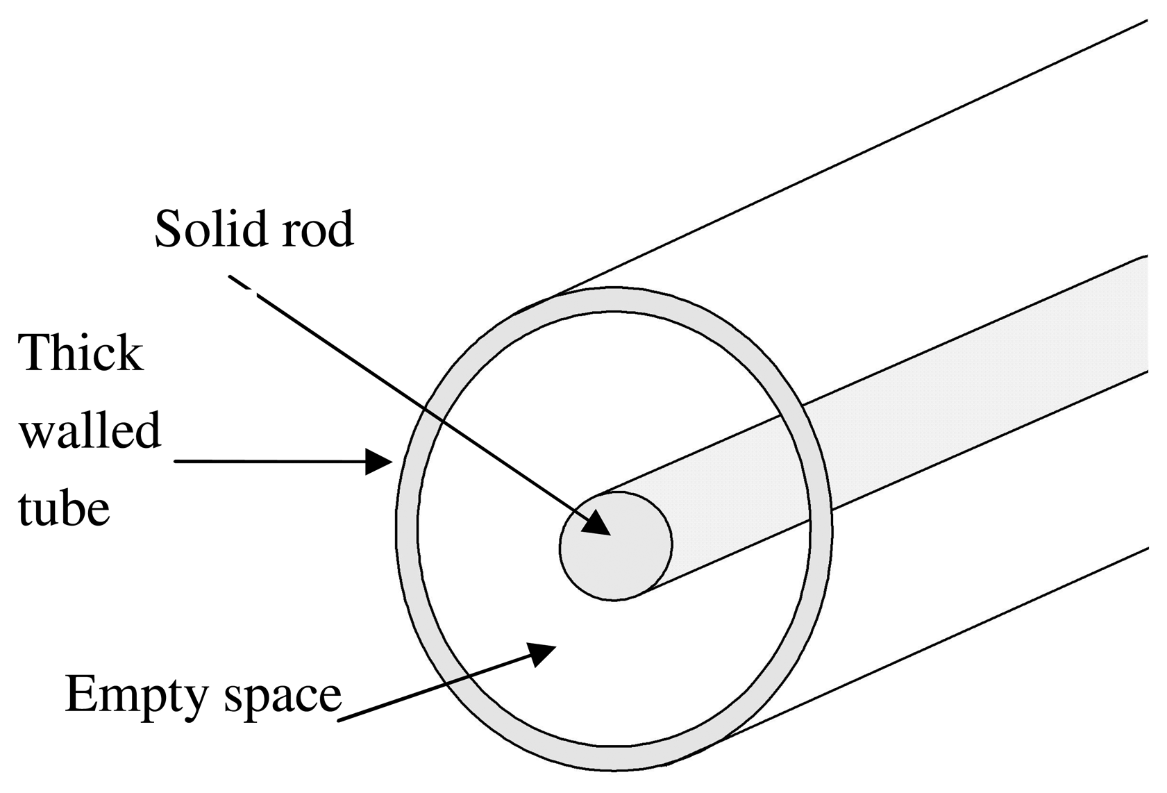
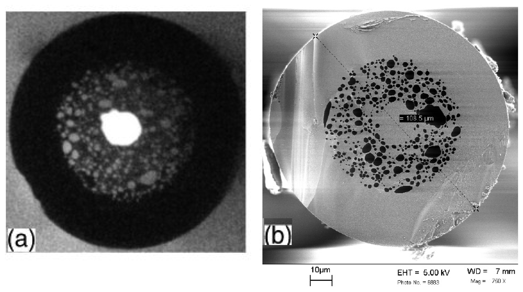
2.1 Fabrication of RHOF

The fabrication process for the RHOF fibers used in this study has been described in detail previously in [2, 3, 14], but will be described here to aid in the understanding and interpretation of the radiation exposure results. A preform is made by placing a 2.5 mm diameter solid rod of fused quartz in the middle of a thick walled tube (9 mm ID, 15 mm OD) made of the same material as shown in figure 1.
The empty space surrounding the solid core was filled with 100-mesh size, 99.7% purity silica powder mixed with 0.075 wt.% silicon nitride (Si3N4). It has been shown that silicon nitride produced the most successful fibers among the materials tested [14]. When the assembly is heated in the graphite element furnace in the draw tower, the silicon nitride oxidizes using the oxygen present in the interstitial spaces between the grains of the silica powder. The by-product of the oxidation reaction is silica glass and nitrogen gas [15] that forms small bubbles in the molten glass. This is referred to as “in-situ” bubble formation. It is believed that existence of nitrogen traces within the fiber's structure does not degrade its optical properties. In fact, it has been reported that doping silica fibers with nitrogen increases their radiation resistance [16]. Thus, during the fiber drawing process, the silica powder fuses into a single mass preventing any generated gas from escaping. Then, as the temperature increases, the silicon nitride oxidizes more rapidly, releasing nitrogen (or NOx) gas which forms the bubbles. When the silica softens, the spherical bubbles are drawn out into long thin tubules as the fiber is drawn from the preform. The fiber was then coated with Desolite™ polyurethane acrylate which is an ultraviolet cured polymer. An optical micrograph taken in transmission mode (a) and an SEM micrograph (b) of one of the fabricated fibers are shown in figure 2. Analysis of the SEM micrographs of some of these fibers showed that they contained over a thousand air holes with sizes ranging from less than 100 nm to more than 10 μm.

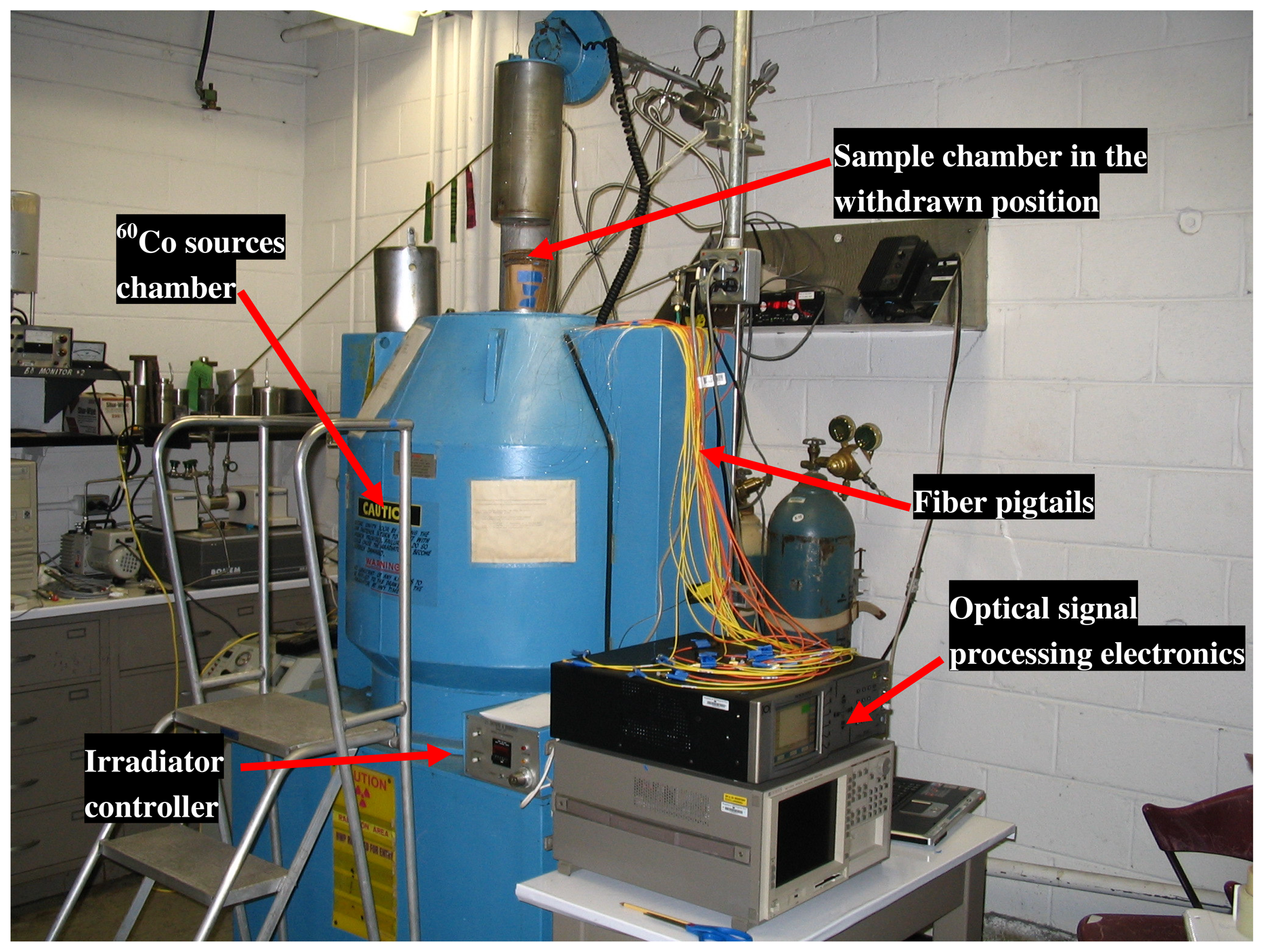
2.2. Experimental setup

To study the behavior of the RHOF under gamma irradiation, its radiation response in air at room temperature was compared to those of germanium doped core pure silica cladding fibers. Standard telecommunication SMF and MMF (Corning SMF-28e and InfiniCor 600 respectively) were used. Harsh environment pure silica core, fluorine down-doped inner cladding, and pure silica outer cladding fiber (SMF-40-CP-125-1, Verrillon, Inc.), which is referred to here as pure silica core (PSC) fiber, was also used in this study. Two RHOF from the same spool, “as made” and “methanol washed” were tested. RHOF washing was done by flowing methanol through the holes using a pressurized solvent reservoir. The five, 10 cm long, fiber samples were wound and fixed on 10 cm diameter rigid “flat spools” and spliced to labeled standard pigtails using a standard high quality fusion splicer (Type-36 Fusion Splicer, Sumitomo). Fixing the fiber samples on a rigid surface allowed easy handling and eliminated significant bending loss variations. Fiber optic connection cables, SMF (8.3/125) and MMF (50/125), simplex with standard FC/FC connectors (Stonewall Cable, Inc.) were used for SMF and MMF pigtails.
The fiber irradiation test was performed under a high-intensity gamma ray field (4×10⁴ rad/hr as of the time of testing) at an Oak Ridge National Laboratory gamma ray irradiation facility using the J.L. Shepherd irradiator which contains 60Co (1173 keV and 1332 keV gamma rays) cylindrical sealed sources. The irradiator had a sample chamber with a 15 cm diameter and 20 cm high cavity as shown in figure 3.
With the sample chamber in the withdrawn position, the fiber samples were stacked in the middle of the sample chamber and connected to the optical signal detection electronics. Two instruments were used for optical signal detection, one was used to measure the radiation-induced absorption (RIA) centered at 1550 nm and the other was to measure the broadband spectrum in order to capture the radiation-induced luminescence (RIL) and Cerenkov emission if present. A high-resolution component testing system (CTS), which is essentially a spectrometer with a built-in tunable laser source and a detector, (Si720, Micron Optics Inc.) was used for the RIA measurements. This system contains a 1 mW fiber ring laser that is continuously swept from 1520 to 1570 nm with wavelength accuracy of 1 pm and has dynamic range detection capability of more than 60 dBm. An Ando optical spectrum analyzer (OSA) (AQ-6315E, Yokogawa Corp.) was used for the RIL measurements. This system spectrally resolves intensity measurements in the range 350-1750 nm with wavelength accuracy better than 0.05 nm. The system is sensitive enough to measure light intensities as low as a few picowatts.
Reference measurements were taken before the sample chamber was inserted into the irradiation position. When the irradiation test was completed, the fiber samples were kept in the dark for a period of time and then exposed to ambient light to assess post irradiation recovery behavior.

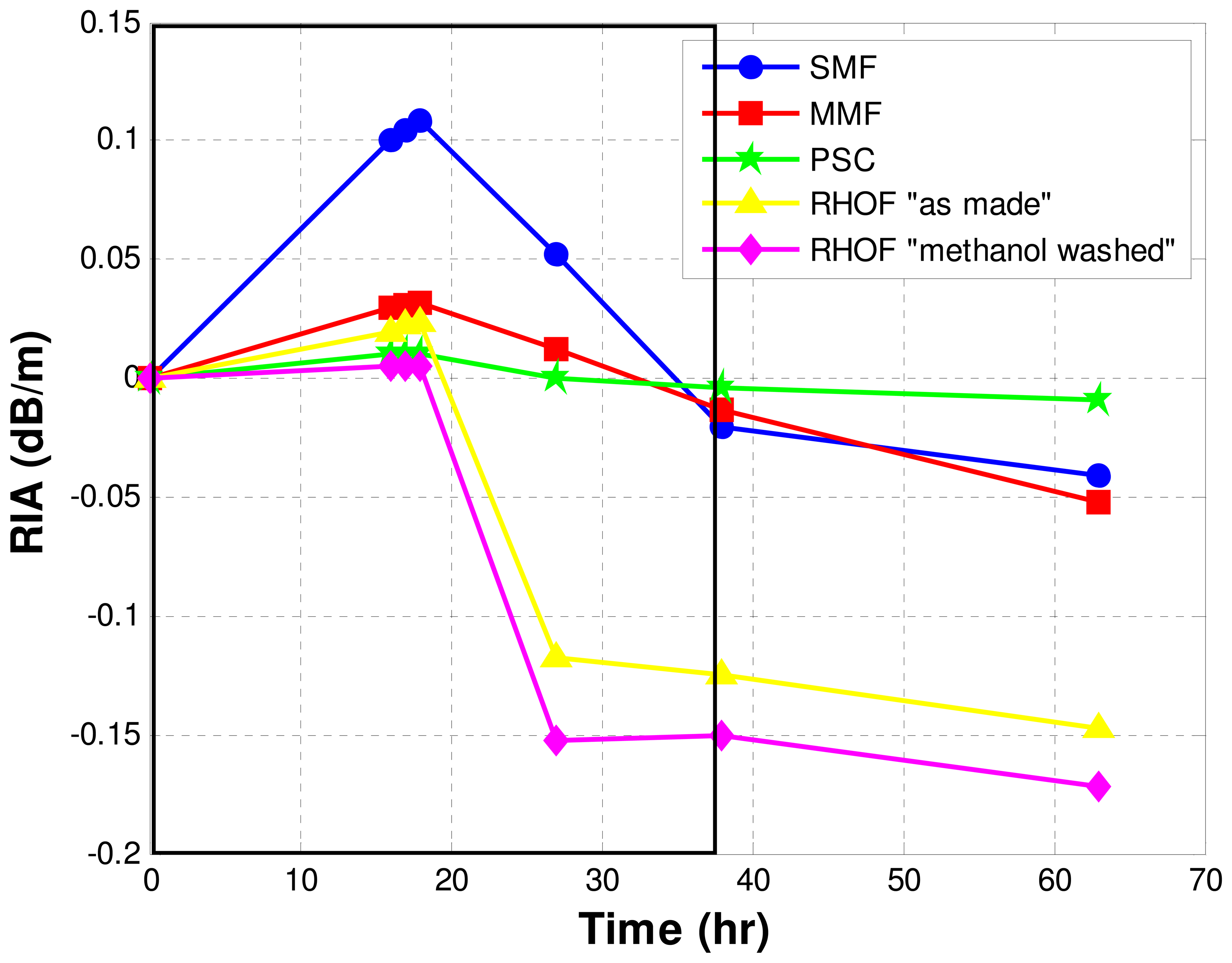
3. Results and Discussion

The fabricated RHOFs used in this study had an outer diameter of 110 μm with variation of about ± 10 μm, and a core of about 20 μm. These fibers have been experimentally shown to be highly multimoded as evidenced by the far field patterns. The fiber dimensions allowed the used of standard fiber splicing tools such as cleavers and fusion splicers. The PCF-to-standard-silica-fiber splicing procedure reported in [17] was followed in splicing RHOF to standard single-mode fiber (SMF) and multi-mode fiber (MMF) pigtails.
Since there is a core size mismatch between RHOF (20 μm) and SMF and MMF (9 μm and 50 μm respectively) optical loss at the splice junction could not be avoided. It was necessary to determine the best splice configuration that will result in minimum optical loss. Two configurations were tested. In the first configuration, which is referred to as large-to-small (LTS), light propagates from the large core (MMF) into the medium core (RHOF) and then into the small core (SMF). In the second configuration, which is referred to as small-to-large (STL), light propagates in the opposite direction from the small core (SMF) into the medium core (RHOF) and then into the relatively large core (MMF). Results showed that LTS configuration had less optical loss by about 1 dB. All fiber pigtail preparations were done in the Center for Photonics Technology at Virginia Tech.
Under gamma irradiation, optical signals propagating in optical fibers are affected by RIA and RIL which is usually accompanied by Cerenkov emission [18]. RIA can be described simply as the difference in dB between the transmitted optical power in the fiber before and after radiation exposure divided by the fiber length [19]. It is usually expressed by:
RIA ( λ , t ) = 10 L log ( P ( λ , t ) P ( λ , t o ) )
where λ is the wavelength, t is the irradiation time, L is the length of the fiber, P is the optical power in Watts and to is the irradiation start time. RIA in the near-IR region is typically small compared to that experienced in the UV region [20]. The absorption peaks responsible for RIA in UV-visible regions are associated with the formation of color centers such as non-bridging oxygen hole centers (NBOHC) with a band at 630 nm [18], oxygen vacancies (E') with a band at 215 nm [9], point defects related to impurities in silica like chlorine, for example, with a band around 330 nm [21], germanium related defects with a band at 475 nm [19], and many others. The origin of the incremental growth of the near-IR RIA, in low-OH fibers, is mainly attributed to the UV-visible absorption band tails [22]. However, the presence of color center absorption peaks in the upper end of the near-IR region (>1800 nm) [22], and self trapped holes with a band at 1800 nm [23] have also been reported to contribute to the near-IR RIA. In high-OH fibers, the near-IR RIA has been reported to be due to excitation of the OH vibrational band [8].
Figures 4 and 5 demonstrate spectra of the optical signals transmitted in the sample fibers at to and t = 16 hours respectively. Hereafter in this paper, the results are labeled according to the following color scheme: SMF (blue), MMF (red), PSC (green), RHOF “as made” (yellow), RHOF “ methanol washed” (magenta), to aid the reader in interpretation and comparison. Although the exact reason is not known for sure, the reason that the “as made” and “methanol washed” RHOFs have different transmitted optical power could be related to the splice induced loss as discussed above and the residual liquid methanol inside the fiber's holes. The presented results show that for SMFs, RIA is uniform over the 1520-1570 nm window, and for MMFs is wavelength dependent, even over such a narrow spectral window. This is attributed to the inherent multimode nature of the light propagation in MMFs. Furthermore, RIL and/or Cerenkov emission were not detected by the OSA in any of the fibers. This could be due to the relatively short length of the fibers being irradiated.
Figure 6 demonstrates the RIA for the first 16 hours of irradiation in the sample fibers. Time zero represents the fiber attenuation state before irradiation. Linear behavior, at dose values < 106 rad, was observed in all fiber samples except the PSC fiber. The results for SMF and MMF are comparable with the data published by NASA Goddard Space Flight Center on radiation data for commercially available optical fiber [24]. Since MMF fibers carry larger optical power than SMF fibers, the RIA in MMF fibers is less than on SMF due to photobleaching. The RIA in the PSC fiber, which has the SMF structure, saturates at 0.01 dB. RHOF samples, which have a MMF structure, have a much lower RIA compared to the standard fibers. The RIA in the 1550 nm window in the RHOF could be linked to the OH absorption band tail. It has been shown that the RHOF has a strong OH absorption band at 1385 nm [2]. However, for a reason as yet unknown, the methanol washed RHOF sample showed superior resistance to radiation compared to the “as made” RHOF fiber. Therefore, it is possible that some other mechanism contribute to the observed RIA in the RHOF fibers. We consider the existence of mechanisms, which were proposed for RIA in PCF [13], such as fabrication related defects, and the influence of the confined air within the RHOF microstructure. The material type and purity used in the preform as well as drawing conditions which include speed, temperature and tension can influence the RIA in optical fibers as reported in the literature [25]. Due to the nature of the RHOF structure, not all the optical signal propagating through the fiber is confined in the core region. This has been clearly shown in the use of RHOF fibers as gas sensors [26]. The evanescent field of the optical signal interacts with gases inside the holes in the RHOF fiber and can clearly be seen as absorption peaks in the transmitted optical signal. Therefore, defects in the bulk portion of the cladding could significantly influence the radiation sensitivity of the fiber. The use of relatively impure powder mixtures in the fabrication process of the RHOF introduces high levels of impurities which could be associated with bulk defects. Moreover, the large number of holes within the fiber structure provides large surface area which in turn introduces large numbers of surface defects to the structure. There is little known about the nature of these surface defects at this point, but we assume that they originate during bubble formation and/or fiber drawing. The air confined within the holes could also play a role in the RIA in RHOFs. The ionized air could interact with the surface generating light absorbing species. The “methanol washed” results support the existence of other mechanisms contributing significantly to the RIA as discussed above and also implies the possibility of employing post-fabrication treatment processes to improve the radiation resistance of the RHOF fibers. Post-fabrication treatment of the PCF with hydrogen gas has been reported to improve the fiber's resistance to radiation [27]. Determining the exact mechanisms responsible for the RIA in RHOF fibers and improving the radiation resistance further will be the subject of future investigation.
Figure 7 shows attenuation during the entire duration of the experiment. The area within the black bordered rectangle represents the time in which the fibers were kept in the dark (away from ambient light). The fibers were then exposed to ambient light after 38 hours from the beginning of the irradiation. This figure shows the recovery behavior of the fiber after the irradiation ceased. The results show a superior recovery time of the RHOF fibers over all of the other fibers tested. This behavior is not completely understood yet, but may be related to the underlying RIA mechanisms. The negative RIA represents improvement in transmission of the optical signal. Post-irradiation negative RIA in fibers has been reported previously [19, 28] and could be attributed to photobleaching.
Based on the current understanding of the RHOF behavior in ionizing radiation environments, we propose a fiber optic radiation sensing system based on scintillation light from scintillator phosphor embedded within the RHOF microstructure. The holes in the RHOF can be coated with a thin film of scintillation phosphors used in the detection of UV, X-ray and gamma radiation enabling multi-radiation detection capability in a single sensing element. Different scintillators with different scintillation light wavelengths could be deposited at different locations in the fiber to add directional capability to the proposed sensor. The scintillation light, generated as a result of the interaction of the ionizing radiation with the phosphors material, will collect inside the fiber core and will be guided to the photo detector. The sensor's signal demodulation system electronics and computer algorithms convert the optical signal to a radioactive dose or dose rate. The efficiency of the sensor can be adjusted by varying the RHOF length and the amount of the scintillation phosphor embedded within the holes as well as the structure of the original RHOF fiber.
For a proof of concept, a piece of RHOF fiber was coated with Yttrium Aluminate: Cerium (Y3Al5O12: Ce) phosphor (Phosphor Technology Ltd). The phosphor emits yellow-green color with a peak wavelength at 550 nm when irradiated with ionizing radiation. This piece of fiber was irradiated with UV radiation as shown in figure 8. The phosphor response to UV was observed as yellow-green color light. Work is under way to further test and characterize the proposed sensor under gamma irradiation.
Potential applications of this sensing system could be for on-line flexible dose rate distribution monitoring in (1) radiation facilities like nuclear power plants, accelerator facilities, and radioactive waste storage sites, (2) environmental protection such as monitoring radioactive fallout from atomic weapons testing, nuclear accidents, and other intrusions of radioactive materials, and (3) clinical nuclear medicine dosimetry.

4. Conclusions

This work presents the results of a study of the behavior of RHOF fibers under gamma irradiation exposure. The response of the RHOF were measured and compared to standard telecommunication (SMF and MMF) fibers and harsh environment pure silica core, fluorine doped fibers. The results showed linear behavior of all fibers except PSC fiber which saturates at 0.01 dB. The RIA at the 1550 nm window in the RHOF fibers could be attributed to the OH absorption band tail. However, the results indicate the existence of other mechanisms responsible for RIA such as bulk and surface defects which are related to the fabrication process and the influence of the air confined within the RHOF microstructure. Moreover, the results show the extremely fast relative recovery time of the RHOF fibers compared to all of the other fibers tested.
Based on the good relative performance of the RHOF fibers in the radiation exposure experiments compared to other types of fibers tested, we proposed a new fiber optic radiation sensing system based on the scintillation light from a scintillator phosphor embedded within the RHOF microstructure. Ultraviolet, X-ray, and gamma radiation sensitive scintillation phosphors can be embedded within the RHOF microstructure for multi-radiation detection. Furthermore, the sensor can have directional capability by coating the sensing element with different scintillators of different light wavelengths at different locations within the fiber.

Acknowledgments

The authors would like to thank Dr. Abdel Soufiane from Verrillon, Inc. for providing a sample of PSC fiber, Ms. Helen Gissing from Phosphor Technology Ltd for providing scintillator phosphors samples, Mr. Vadim Gayshan from Scintillation Technologies for many valuable discussions on scintillation materials, and Prof. Ira Jacobs of Virginia Tech for insightful discussion on optical fiber loss measurements.

References

  1. Knight, J.C.; Birks, T.A.; Russell, P.S.J.; Atkins, D.M. All silica single-mode fiber with photonic crystal cladding. Optics Letters 1996, 21(19), 1547–1549. [Google Scholar]
  2. Kominsky, D.; Pickrell, G.; Stolen, R. Generation of random-hole optical fiber. Optics Letters 2003, 28(16), 1409–11. [Google Scholar]
  3. Pickrell, G.; Kominsky, D.; Stolen, R.; Ellis, F.; Jeong, K.; Safaai-Jazi, A.; Anbo, W. Microstructural analysis of random hole optical fibers. Photonics Technology Letters, IEEE 2004, 16(2), 491–493. [Google Scholar]
  4. Huston, A.L.; Justus, B.L.; Falkenstein, P.L.; Miller, R.W.; Ning, H.; Altemus, R. Remote optical fiber dosimetry. Nuclear Instruments & Methods in Physics Research Section B-Beam Interactions with Materials & Atoms 2001, 184(1-2), 55–67. [Google Scholar]
  5. Friebele, E.J.; Taylor, E.W.; Turguet de Beauregard, G.; Wall, J.A.; Barnes, C.E. Interlaboratory comparison of radiation-induced attenuation in optical fibers. I. Steady-state exposures. Journal of Lightwave Technology 1988, 6(2), 165–171. [Google Scholar]
  6. Taylor, E.W.; Friebele, E.J.; Henschel, H.; West, R.H.; Krinsky, J.A.; Barnes, C.E. Interlaboratory comparison of radiation-induced attenuation in optical fibers. II. steady-state exposures. Journal of Lightwave Technology 1990, 8(6), 967–976. [Google Scholar]
  7. Friebele, E.J.; Lyons, P.B.; Blackburn, J.; Henschel, H.; Johan, A.; Krinsky, J.A.; Robinson, A.; Scheneider, W.; Smith, D.; Taylor, E.W.; Turquet de Beauregard, G.Y.; West, R.H.; Zagarino, P. Interlaboratory comparison of radiation-induced attenuation in optical fibers. III. Transient exposures. Journal of Lightwave Technology 1990, 8(6), 977–989. [Google Scholar]
  8. Brichard, B.; Borgermans, P.; Fernandez, A.F.; Lammens, K.; Decreton, A. Radiation effect in silica optical fiber exposed to intense mixed neutron-gamma radiation field. IEEE Transactions on Nuclear Science 2001, 48(6), 2069–2073. [Google Scholar]
  9. Kakuta, T.; Shikama, T.; Narui, M.; Sagawa, T. Behavior of optical fibers under heavy irradiation. Fusion Engineering and Design 1998, 41(1-4), 201–205. [Google Scholar]
  10. Girard, S.; Keurinck, J.; Ouerdane, Y.; Meunier, J.P.; Boukenter, A. γ-rays and pulsed X-ray radiation responses of germanosilicate single-mode optical fibers: influence of cladding codopants. Journal of Lightwave Technology 2004, 22(8), 1915–1922. [Google Scholar]
  11. Girard, S.; Yahya, A.; Boukenter, A.; Ouerdane, Y.; Meunier, J.P.; Kristiansen, R.E.; Vienne, G. Gamma-radiation-induced attenuation in photonic crystal fibre. Electronics Letters 2002, 38(20), 1169–1171. [Google Scholar]
  12. Kosolapov, A.F.; Nikolin, I.V.; Tomashuk, A.L.; Semjonov, S.L.; Zabezhailov, M.O. Optical losses in as-prepared and gamma-irradiated microstructured silica-core optical fibers. Inorganic Materials 2004, 40(11), 1229–32. [Google Scholar]
  13. Girard, S.; Baggio, J.; Leray, J.L. Radiation-induced effects in a new class of optical waveguides: the air-guiding photonic crystal fibers. IEEE Transactions on Nuclear Science 2005, 52(6), 2683–2688. [Google Scholar]
  14. Kominsky, D. Development of random hole optical fiber and crucible technique optical fibers. PhD Dissertation, Materials Science and Engineering, Virginia Polytechnic Institute and State University, Blacksburg, VA, 2005. [Google Scholar]
  15. Kainasskii, I.S.; Degtyareva, E.V.; Kukhtenko, V.A. Carborundum Products Bonded with Silicon Nitride. Ogneupory 1960, 25(4), 175–80. [Google Scholar]
  16. Dianov, E.M.; Golant, K.M.; Khrapko, R.R.; Tomashuk, A.L. Nitrogen doped silica core fibres: a new type of radiation-resistant fibre. Electronics Letters 1995, 31(17), 1490–1491. [Google Scholar]
  17. Hansen, T.P.; Jes, B.; Jakobsen, C.; Vienne, G.; Simonsen, H.R.; Nielsen, M.D.; Skovgaard, P.M.W.; Folkenberg, J.R.; Bjarklev, A. Air-guiding photonic bandgap fibers: spectral properties, macrobending loss, and practical handling. Journal of Lightwave Technology 2004, 22(1), 11–15. [Google Scholar]
  18. Tomashu, A.L.; Golant, K.M.; Dianov, E.M.; Medvedkov, O.I.; Plaksin, O.A.; Stepanov, V.A.; Stepanov, P.A.; Demenko, P.V.; Chernov, V.M.; Klyamkin, S.N. Radiation-induced absorption and luminescence in specially hardened large-core silica optical fibers. IEEE Transactions on Nuclear Science 2000, 47(3), 693–698. [Google Scholar]
  19. Girard, S.; Baggio, J.; Bisutti, J. 14-MeV Neutron, γ-Ray, and Pulsed X-Ray Radiation-Induced Effects on Multimode Silica-Based Optical Fibers. IEEE Transactions on Nuclear Science 2006, 53(6), 3750–3757. [Google Scholar]
  20. Bondarenko, A.V.; Dyad'kin, A.P.; Kashchuk, Y.A.; Krasil'nikov, A.V.; Polyakov, G.A.; Rastyagaev, I.N.; Skopintsev, D.A.; Tugarinov, S.N.; Yartsev, V.P.; Bogatyrev, V.A.; Tomashuk, A.L.; Klyamkin, S.N.; Bender, S.E. A study of radiation resistance of silica optical fibers under conditions of reactor irradiation. Instruments and Experimental Techniques 2006, 49(2), 190–8. [Google Scholar]
  21. Henschel, H.; Kohn, O.; Weinand, U. A new radiation hard optical fiber for high-dose values. IEEE Transactions on Nuclear Science 2002, 49(3), 1432–1438. [Google Scholar]
  22. Van Uffelen, M.; Jucker, P. Radiation resistance of fiberoptic components and predictive models for optical fiber systems in nuclear environments. IEEE Transactions on Nuclear Science 1998, 45(3), 1558–1565. [Google Scholar]
  23. Girard, S.; Brichard, B.; Baggio, J.; Berghmans, F.; Decreton, M. Comparative Study of Pulsed X-Ray and γ-Ray Radiation-Induced Effects in Pure-Silica-Core Optical Fibers. IEEE Transactions on Nuclear Science 2006, 53(4), 1756–1763. [Google Scholar]
  24. Ott, M.N. Radiation effects data on commercially available optical fiber: database summary. In IEEE Radiation Effects Data Workshop; 2002; IEEE; pp. 24–31. [Google Scholar]
  25. Henschel, H.; Kuhnhenn, J.; Weinand, U. Radiation hard optical fibers. In Optical Fiber Communication Conference Technical Digest; 2005; IEEE; Volume 4, p. 4. [Google Scholar]
  26. Pickrell, G.; Peng, W.; Wang, A. Random-hole optical fiber evanescent-wave gas sensing. Optics Letters 2004, 29(13), 1476–1478. [Google Scholar]
  27. Kosolapov, A.F.; Semjonov, S.L.; Tomashuk, A.L. Improvement of radiation resistance of multimode silica-core holey fibers. In Reliability of Optical Fiber Components, Devices, Systems, and Networks III, Proc. of SPIE; 2006; 6193, pp. 1–7. [Google Scholar]
  28. Sreckovic, M.; Marinovic, A.; Glisic, R.; Rajkovic, V.; Pantelic, S.; Mioc, U.; Kovacevic, M. Properties of fiber optical materials after exposure to nuclear radiation. In 20th International Conference on Microelectronics; 1995; IEEE; Volume 1, pp. 289–292. [Google Scholar]
Figure 1. RHOF preform assembly.
Sensors 07 00676f1
Figure 2. (a) Optical image of RHOF, (b) SEM image of RHOF.
Sensors 07 00676f2
Figure 3. Fiber irradiation setup showing the J.L. Shepherd irradiator.
Sensors 07 00676f3
Figure 4. Transmitted optical spectra of fiber samples at to, SMF (blue), MMF (red), PSC (green), RHOF “as made” (yellow), RHOF “ methanol washed” (magenta).
Sensors 07 00676f4
Figure 5. Transmitted optical spectra of fiber samples at t = 16 hours, SMF (blue), MMF (red), PSC (green), RHOF “as made” (yellow), RHOF “ methanol washed” (magenta).
Sensors 07 00676f5
Figure 6. RIA of the sample fibers for the first 16 hours of irradiation showing the behavior of fibers under irradiation.
Sensors 07 00676f6
Figure 7. RIA of sample fibers for the total duration of the experiment showing the fibers behavior under and post irradiation.
Sensors 07 00676f7
Figure 8. Phosphor response to UV in the coated RHOF fiber.
Sensors 07 00676f8

