1. Introduction
Various methods have been proposed in the literature for measuring the optical properties of gases and liquids incorporated inside the holes of structured optical fibres. A straightforward approach uses a solid-core photonic crystal fibre (PCF) and relies on the overlap between the evanescent field of the propagating mode and the holes [
1,
2]. Higher sensitivity can be achieved by exploiting guidance in the hollow core of diffractive fibres [
3-
5] since light propagates through the sample and interaction is maximum. The refractive index of the sample, however, needs to be considered since it will shift the transmission band. A major factor that will influence the ultimate fibre employed is the ability to inscribe gratings [
6,
7]. Solid fibre Bragg grating based refractive index sensors have also been proposed in the past [
8-
11].
Solid-core photonic crystal fibres are often described by an analogous effective step index fibre. The effective core and cladding can be highly sensitive to the extent of the modal field into the cladding. As a consequence of the high core-cladding index contrast the contribution to modal propagation from the periodic arrangement of holes is negligible when the wavelength of light is larger than the bridge thickness between the holes but smaller than the core diameter. On the other hand, for less confined modes or when the wavelength of light is commensurate or smaller than the interstitial hole spacing, as well as the core size itself, the periodic lattice provides phase conditions that allow coherent scattering of light and therefore diffractive confinement [
12]. This resonant phenomenon has been observed in bending loss tests where light leaks out from the core and is launched into the cladding, generating a short wavelength cut-off in the fibre transmission band [
13]. This short wavelength cut-off is sensitive to the perturbations applied to the fibre as well as the index of the material within the hole.
In this paper we propose a new optical fibre sensing approach exploiting the high sensitivity of resonant propagation of less confined light in solid-core photonic crystal fibres. Corrugations are inserted at the silica/hole interface as a result of a photorefractive grating written using two-photon induced densification [
14]. The UV written grating is a controllable and reproducible way of generating corrugations at the hole/silica interface and for this application it is used only to generate scattering loss (couple light from the core into the cladding). To a first approximation, the diffractive condition of the cladding is determined radially with respect to the core permitting a simple linear Bragg analysis. The veracity of this simple technique applied to sensing is tested by monitoring the phase transition of water to ice.
2. Materials and Method
Details of the particular fibre used in these experiments, including fabrication, have been reported elsewhere [
6]. The 1 cm long grating is directly written into a 20 cm long piece of the PCF with an ArF laser (193 nm,
τpulse = 15 ns, r.r. = 40 Hz) through an optical phase mask (
λmask = 1061.5 nm). The two-photon triggered excitation breaks the Si-O bond of the silica fibre generating densification in the glass. This leads to periodic corrugations along the hole-glass interfaces [
14].
Although scattering losses tend to be uniform over a large spectral range, the less confined modes (at short wavelengths) will experience higher loss since they interact more with the glass/hole interface. When the scattered light reaches the periodic lattice of the cladding, coherent scattering will take place for the wavelengths that match a particular phase condition imposed by the structure. Some of this light may couple back into the core. The short wavelength cut-off in the transmission band of the fibre is defined by the high confinement loss at short wavelengths and the diffraction condition of the cladding, which appears sharp because of the diffractive nature of the phenomenon. The less confined modes at distinct wavelengths that do not match the resonant condition of the cladding will leak out of the fibre.
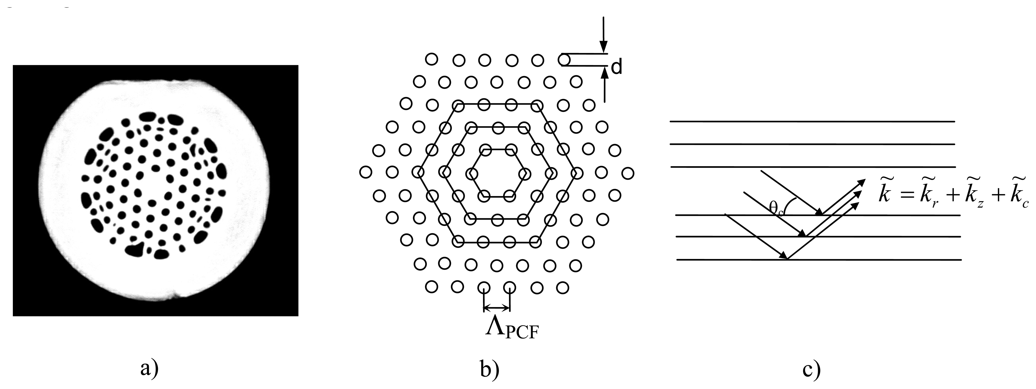
Figure 1(a)-(c) is a depiction of the fibre cross-section and the grating resonance conditions that need to be satisfied. A ring of holes placed in a hexagon pattern around the core establishes the radial condition for resonant scattering.
Figure 1(c) depicts the phase matching condition along the fibre. For a simple analytic 1-D model we treat the hexagon rings as circular so there is no variation in the grating around the core.
Using the Bragg equation the resonant wavelengths as well as the critical angles for each diffractive order of the periodic lattice can be estimated. The critical angle,
θc, determines propagation along the fibre. Each resonant wavelength is related to a critical angle:
here
m is the diffraction order,
λ is the wavelength of the phase-matched wave,
λ is the pitch between the rings of holes,
n is the refractive index of silica,
θc is given by [
15]:
θc =
cos-1 (
ncladding/
ncore),
ncore and
ncladding are the effective refractive index of the core and cladding respectively. When the wavelength is commensurate with the interstitial spacing and strong confinement is achieved, the resonance condition of
(1) is not observed. It should be noted, however, that if the core itself is very small the mode field for longer wavelengths will see the lattice and diffractive guidance will arise if the phase matching condition is appropriate. Angular dependence of the resonant light is shown in
Figure 1(c). At the Bragg condition in-phase addition of the reflected light will occur.
From the Bragg condition the first diffractive orders correspond to long wavelengths that are well bound in the fibre core and any diffractive contribution of the cladding structure is not observed. As
m increases the resonant wavelength decreases. The short wavelength cut-off will correspond to a high value of
m. Replacing
θc in
Equation (1) and re-arranging yields an effective index of the cladding:
This provides the basis for a novel approach to refractive index measurements using the lattice structure of the cladding. The effective index is therefore dependent on the index of the material within the holes. Since the approach is exploiting a direct resonance within this lattice, the method is expected to be more sensitive than a single pass measurement technique. The field in the cladding is originated from scattering at a high index contrast and rough interface. By definition this generates scattering at all directions. This is supported by the high transmission loss at the scattering region and by HeNe light transmission investigation presenting uniform scattering at all directions. Hence the field can be considered uniform in the holes and silica and the effective index can be approximate by:
ncladding =
xhnh +
xSiO2nSiO2, where
xSiO2 and
xh are the fractions of silica and holes that make up the cladding respectively and
nh is the index of the medium within the holes and
nSiO2 the index of SiO
2. The hole fraction,
xh, is estimated measuring the size of the holes and the quantity of holes from an image of the fibre cross-section taken with an optical microscope. The picture resolution will affect the uncertainty of the measurement. The estimated
xh is ∼0.27. The refractive index within the holes is therefore:
This equation is also likely to overestimate the index as it does not consider the actual evanescent field distribution within the holes arising from reflection from the various interfaces in the 2-D structure. The amount of evanescent field is negligible in comparison to the scattered light, as was demonstrated with a HeNe laser. However, a small amount of error will be introduced though the final results indicate this is not significant and can in principle be calibrated out. The hole fraction is consequently a critical source of error in this technique. Generally, the field is less than anticipated and a more accurate assessment requires full numerical evaluation of the field distribution as well as the effective index [
16]. Using this approximation the refractive index of a material inserted into the holes can be determined by measuring the shift in the short wavelength cut-off of a photonic crystal fibre. The refractive index,
n, is approximately the core index of SiO
2 (
nSiO2).
3. Results and Discussion
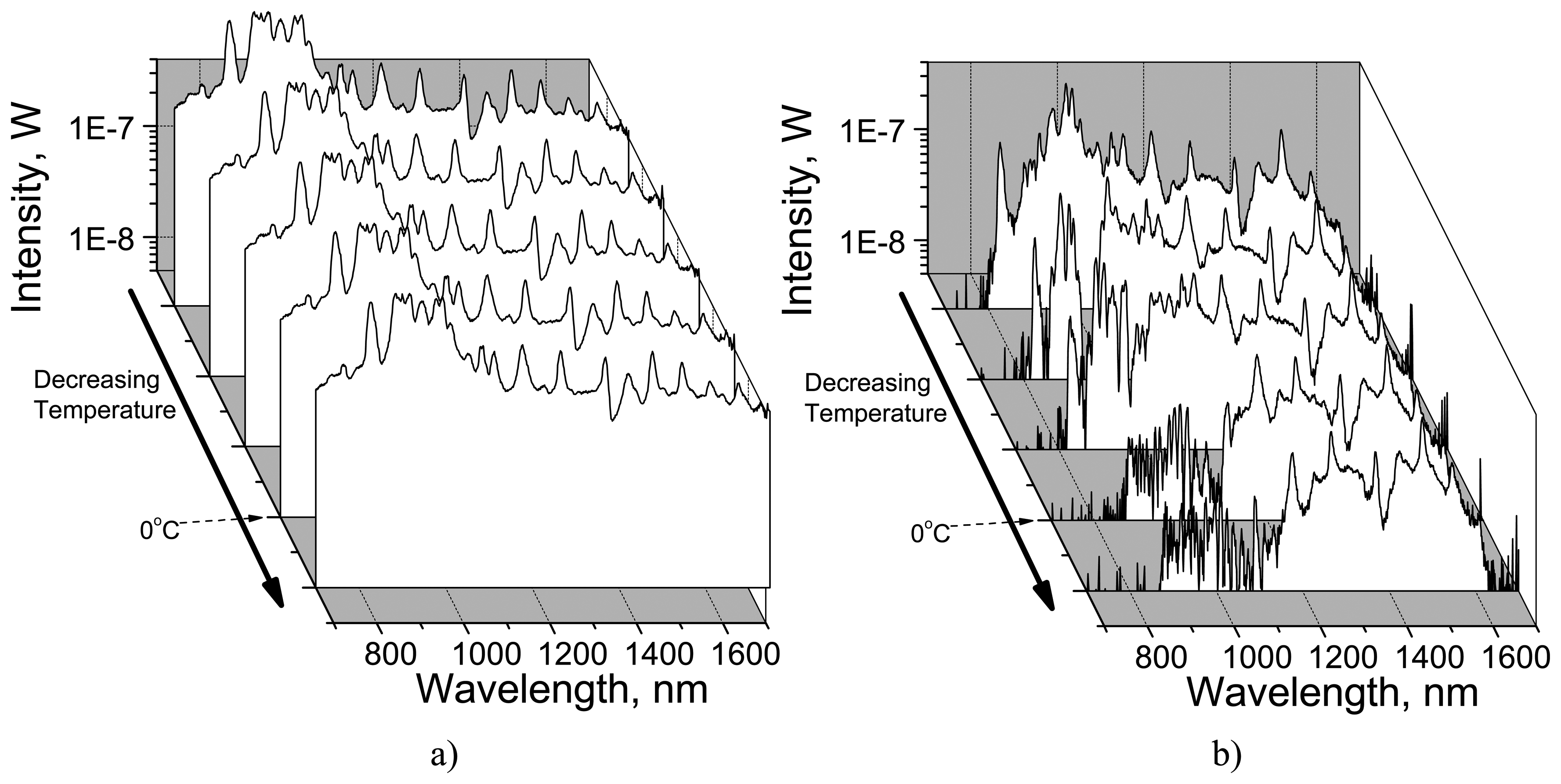
To verify the approach experimentally, water was incorporated into identical photonic crystal fibres. One contained a grating while the other remained pristine for comparison. The transmission spectra were used to characterise the fibres. The fibres were kept straight with identical constant tension throughout all the measurements. The transmission spectra were monitored using a white light source and optical spectrum analyser (OSA), whilst cooling the fibres from room temperature to below -7 °C.
Figure 2 shows the transmission band spectra of both fibres during cooling. For the fibre without the grating there is no significant variation (
Figure 2(a)). On the other hand, for the sample containing the grating a cut-off at short wavelengths is clearly observed. It shifts to longer wavelengths during cooling (
Figure 2(b)).
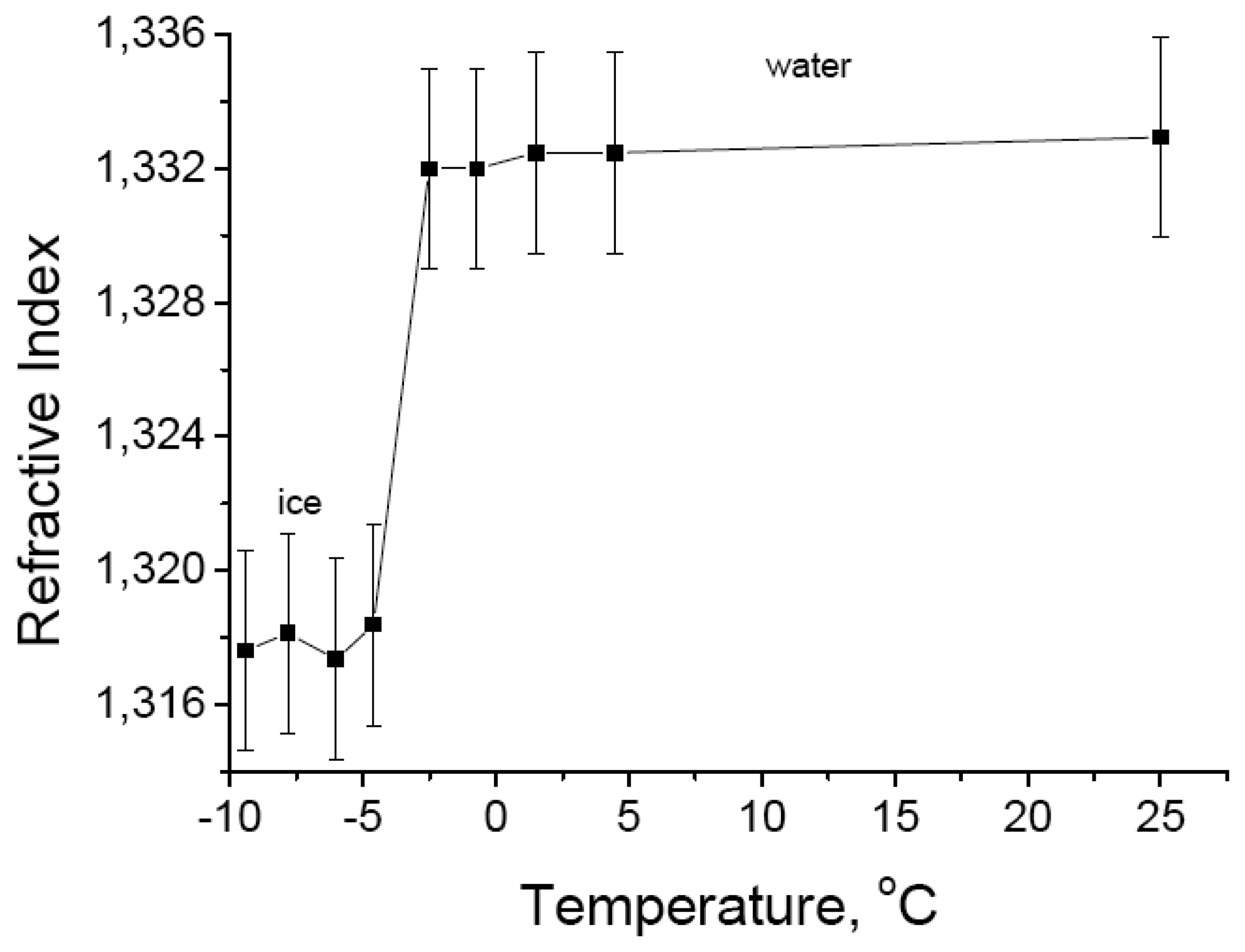
By measuring the corresponding wavelength shift of the transmission band edge with temperature and using
Equation (3), the refractive index of the material inside the holes during the transition from water to ice can be extracted and plotted as a function of temperature (
Figure 3). The refractive index of water is used as a reference value to determine the diffraction order
m in
Equation (3) and found to be
m = 5. The estimated refractive index of ice at -7 °C is
nice ∼ (1.318±0.003) which is in fair agreement with that reported in the literature:
nice = 1.305 [
17]. The small difference between the measured refractive index and reported values is explained by noting that the grating corrugations inside the small capillary channels restrict free volume expansion of the water upon freezing [
14]. The resultant compression leads to a slightly higher density and hence a higher refractive index. A ∼10 nm thick super cooled liquid-like layer (
nSCL ∼
nwater = 1.333) formed at the silica/ice interface may also contribute to this difference [
18]. The ±0.003 error is estimated for a 5% error in the estimation of
xh (
Equation (3)). The effect of the temperature variation on the lattice resonance introduces an error of ∼0.0005 in the measured refractive index, which is much smaller than the experimental error. It is also possible to use this sensor the other way around and by measuring the refractive index estimate the temperature.
